CN100468279C - Obtaining external clocks for multiple synchronous computers - Google Patents
Obtaining external clocks for multiple synchronous computersDownload PDFInfo
- Publication number
- CN100468279C CN100468279CCNB038046040ACN03804604ACN100468279CCN 100468279 CCN100468279 CCN 100468279CCN B038046040 ACNB038046040 ACN B038046040ACN 03804604 ACN03804604 ACN 03804604ACN 100468279 CCN100468279 CCN 100468279C
- Authority
- CN
- China
- Prior art keywords
- signal
- clock
- input signal
- reference signal
- input
- Prior art date
- Legal status (The legal status is an assumption and is not a legal conclusion. Google has not performed a legal analysis and makes no representation as to the accuracy of the status listed.)
- Expired - Lifetime
Links
Images


Classifications
- H—ELECTRICITY
- H02—GENERATION; CONVERSION OR DISTRIBUTION OF ELECTRIC POWER
- H02H—EMERGENCY PROTECTIVE CIRCUIT ARRANGEMENTS
- H02H7/00—Emergency protective circuit arrangements specially adapted for specific types of electric machines or apparatus or for sectionalised protection of cable or line systems, and effecting automatic switching in the event of an undesired change from normal working conditions
- H02H7/26—Sectionalised protection of cable or line systems, e.g. for disconnecting a section on which a short-circuit, earth fault, or arc discharge has occured
- H02H7/261—Sectionalised protection of cable or line systems, e.g. for disconnecting a section on which a short-circuit, earth fault, or arc discharge has occured involving signal transmission between at least two stations
- H02H7/262—Sectionalised protection of cable or line systems, e.g. for disconnecting a section on which a short-circuit, earth fault, or arc discharge has occured involving signal transmission between at least two stations involving transmissions of switching or blocking orders
- G—PHYSICS
- G06—COMPUTING OR CALCULATING; COUNTING
- G06F—ELECTRIC DIGITAL DATA PROCESSING
- G06F1/00—Details not covered by groups G06F3/00 - G06F13/00 and G06F21/00
- G06F1/04—Generating or distributing clock signals or signals derived directly therefrom
- G06F1/12—Synchronisation of different clock signals provided by a plurality of clock generators
- G—PHYSICS
- G06—COMPUTING OR CALCULATING; COUNTING
- G06F—ELECTRIC DIGITAL DATA PROCESSING
- G06F3/00—Input arrangements for transferring data to be processed into a form capable of being handled by the computer; Output arrangements for transferring data from processing unit to output unit, e.g. interface arrangements
- G06F3/05—Digital input using the sampling of an analogue quantity at regular intervals of time, input from a/d converter or output to d/a converter
- H—ELECTRICITY
- H01—ELECTRIC ELEMENTS
- H01H—ELECTRIC SWITCHES; RELAYS; SELECTORS; EMERGENCY PROTECTIVE DEVICES
- H01H83/00—Protective switches, e.g. circuit-breaking switches, or protective relays operated by abnormal electrical conditions otherwise than solely by excess current
- H01H83/20—Protective switches, e.g. circuit-breaking switches, or protective relays operated by abnormal electrical conditions otherwise than solely by excess current operated by excess current as well as by some other abnormal electrical condition
- H—ELECTRICITY
- H02—GENERATION; CONVERSION OR DISTRIBUTION OF ELECTRIC POWER
- H02H—EMERGENCY PROTECTIVE CIRCUIT ARRANGEMENTS
- H02H3/00—Emergency protective circuit arrangements for automatic disconnection directly responsive to an undesired change from normal electric working condition with or without subsequent reconnection ; integrated protection
- H02H3/006—Calibration or setting of parameters
- H—ELECTRICITY
- H02—GENERATION; CONVERSION OR DISTRIBUTION OF ELECTRIC POWER
- H02H—EMERGENCY PROTECTIVE CIRCUIT ARRANGEMENTS
- H02H7/00—Emergency protective circuit arrangements specially adapted for specific types of electric machines or apparatus or for sectionalised protection of cable or line systems, and effecting automatic switching in the event of an undesired change from normal working conditions
- H02H7/26—Sectionalised protection of cable or line systems, e.g. for disconnecting a section on which a short-circuit, earth fault, or arc discharge has occured
- H02H7/261—Sectionalised protection of cable or line systems, e.g. for disconnecting a section on which a short-circuit, earth fault, or arc discharge has occured involving signal transmission between at least two stations
- H02H7/263—Sectionalised protection of cable or line systems, e.g. for disconnecting a section on which a short-circuit, earth fault, or arc discharge has occured involving signal transmission between at least two stations involving transmissions of measured values
- H—ELECTRICITY
- H02—GENERATION; CONVERSION OR DISTRIBUTION OF ELECTRIC POWER
- H02H—EMERGENCY PROTECTIVE CIRCUIT ARRANGEMENTS
- H02H7/00—Emergency protective circuit arrangements specially adapted for specific types of electric machines or apparatus or for sectionalised protection of cable or line systems, and effecting automatic switching in the event of an undesired change from normal working conditions
- H02H7/26—Sectionalised protection of cable or line systems, e.g. for disconnecting a section on which a short-circuit, earth fault, or arc discharge has occured
- H02H7/30—Staggered disconnection
- H—ELECTRICITY
- H02—GENERATION; CONVERSION OR DISTRIBUTION OF ELECTRIC POWER
- H02J—CIRCUIT ARRANGEMENTS OR SYSTEMS FOR SUPPLYING OR DISTRIBUTING ELECTRIC POWER; SYSTEMS FOR STORING ELECTRIC ENERGY
- H02J13/00—Circuit arrangements for providing remote indication of network conditions, e.g. an instantaneous record of the open or closed condition of each circuitbreaker in the network; Circuit arrangements for providing remote control of switching means in a power distribution network, e.g. switching in and out of current consumers by using a pulse code signal carried by the network
- H02J13/00001—Circuit arrangements for providing remote indication of network conditions, e.g. an instantaneous record of the open or closed condition of each circuitbreaker in the network; Circuit arrangements for providing remote control of switching means in a power distribution network, e.g. switching in and out of current consumers by using a pulse code signal carried by the network characterised by the display of information or by user interaction, e.g. supervisory control and data acquisition systems [SCADA] or graphical user interfaces [GUI]
- H—ELECTRICITY
- H02—GENERATION; CONVERSION OR DISTRIBUTION OF ELECTRIC POWER
- H02J—CIRCUIT ARRANGEMENTS OR SYSTEMS FOR SUPPLYING OR DISTRIBUTING ELECTRIC POWER; SYSTEMS FOR STORING ELECTRIC ENERGY
- H02J13/00—Circuit arrangements for providing remote indication of network conditions, e.g. an instantaneous record of the open or closed condition of each circuitbreaker in the network; Circuit arrangements for providing remote control of switching means in a power distribution network, e.g. switching in and out of current consumers by using a pulse code signal carried by the network
- H02J13/00006—Circuit arrangements for providing remote indication of network conditions, e.g. an instantaneous record of the open or closed condition of each circuitbreaker in the network; Circuit arrangements for providing remote control of switching means in a power distribution network, e.g. switching in and out of current consumers by using a pulse code signal carried by the network characterised by information or instructions transport means between the monitoring, controlling or managing units and monitored, controlled or operated power network element or electrical equipment
- H02J13/00007—Circuit arrangements for providing remote indication of network conditions, e.g. an instantaneous record of the open or closed condition of each circuitbreaker in the network; Circuit arrangements for providing remote control of switching means in a power distribution network, e.g. switching in and out of current consumers by using a pulse code signal carried by the network characterised by information or instructions transport means between the monitoring, controlling or managing units and monitored, controlled or operated power network element or electrical equipment using the power network as support for the transmission
- H02J13/00009—Circuit arrangements for providing remote indication of network conditions, e.g. an instantaneous record of the open or closed condition of each circuitbreaker in the network; Circuit arrangements for providing remote control of switching means in a power distribution network, e.g. switching in and out of current consumers by using a pulse code signal carried by the network characterised by information or instructions transport means between the monitoring, controlling or managing units and monitored, controlled or operated power network element or electrical equipment using the power network as support for the transmission using pulsed signals
- H—ELECTRICITY
- H02—GENERATION; CONVERSION OR DISTRIBUTION OF ELECTRIC POWER
- H02J—CIRCUIT ARRANGEMENTS OR SYSTEMS FOR SUPPLYING OR DISTRIBUTING ELECTRIC POWER; SYSTEMS FOR STORING ELECTRIC ENERGY
- H02J13/00—Circuit arrangements for providing remote indication of network conditions, e.g. an instantaneous record of the open or closed condition of each circuitbreaker in the network; Circuit arrangements for providing remote control of switching means in a power distribution network, e.g. switching in and out of current consumers by using a pulse code signal carried by the network
- H02J13/00006—Circuit arrangements for providing remote indication of network conditions, e.g. an instantaneous record of the open or closed condition of each circuitbreaker in the network; Circuit arrangements for providing remote control of switching means in a power distribution network, e.g. switching in and out of current consumers by using a pulse code signal carried by the network characterised by information or instructions transport means between the monitoring, controlling or managing units and monitored, controlled or operated power network element or electrical equipment
- H02J13/00012—Circuit arrangements for providing remote indication of network conditions, e.g. an instantaneous record of the open or closed condition of each circuitbreaker in the network; Circuit arrangements for providing remote control of switching means in a power distribution network, e.g. switching in and out of current consumers by using a pulse code signal carried by the network characterised by information or instructions transport means between the monitoring, controlling or managing units and monitored, controlled or operated power network element or electrical equipment using an auxiliary transmission line
- H—ELECTRICITY
- H02—GENERATION; CONVERSION OR DISTRIBUTION OF ELECTRIC POWER
- H02J—CIRCUIT ARRANGEMENTS OR SYSTEMS FOR SUPPLYING OR DISTRIBUTING ELECTRIC POWER; SYSTEMS FOR STORING ELECTRIC ENERGY
- H02J13/00—Circuit arrangements for providing remote indication of network conditions, e.g. an instantaneous record of the open or closed condition of each circuitbreaker in the network; Circuit arrangements for providing remote control of switching means in a power distribution network, e.g. switching in and out of current consumers by using a pulse code signal carried by the network
- H02J13/00006—Circuit arrangements for providing remote indication of network conditions, e.g. an instantaneous record of the open or closed condition of each circuitbreaker in the network; Circuit arrangements for providing remote control of switching means in a power distribution network, e.g. switching in and out of current consumers by using a pulse code signal carried by the network characterised by information or instructions transport means between the monitoring, controlling or managing units and monitored, controlled or operated power network element or electrical equipment
- H02J13/00016—Circuit arrangements for providing remote indication of network conditions, e.g. an instantaneous record of the open or closed condition of each circuitbreaker in the network; Circuit arrangements for providing remote control of switching means in a power distribution network, e.g. switching in and out of current consumers by using a pulse code signal carried by the network characterised by information or instructions transport means between the monitoring, controlling or managing units and monitored, controlled or operated power network element or electrical equipment using a wired telecommunication network or a data transmission bus
- H—ELECTRICITY
- H02—GENERATION; CONVERSION OR DISTRIBUTION OF ELECTRIC POWER
- H02J—CIRCUIT ARRANGEMENTS OR SYSTEMS FOR SUPPLYING OR DISTRIBUTING ELECTRIC POWER; SYSTEMS FOR STORING ELECTRIC ENERGY
- H02J13/00—Circuit arrangements for providing remote indication of network conditions, e.g. an instantaneous record of the open or closed condition of each circuitbreaker in the network; Circuit arrangements for providing remote control of switching means in a power distribution network, e.g. switching in and out of current consumers by using a pulse code signal carried by the network
- H02J13/00006—Circuit arrangements for providing remote indication of network conditions, e.g. an instantaneous record of the open or closed condition of each circuitbreaker in the network; Circuit arrangements for providing remote control of switching means in a power distribution network, e.g. switching in and out of current consumers by using a pulse code signal carried by the network characterised by information or instructions transport means between the monitoring, controlling or managing units and monitored, controlled or operated power network element or electrical equipment
- H02J13/00028—Circuit arrangements for providing remote indication of network conditions, e.g. an instantaneous record of the open or closed condition of each circuitbreaker in the network; Circuit arrangements for providing remote control of switching means in a power distribution network, e.g. switching in and out of current consumers by using a pulse code signal carried by the network characterised by information or instructions transport means between the monitoring, controlling or managing units and monitored, controlled or operated power network element or electrical equipment involving the use of Internet protocols
- H—ELECTRICITY
- H02—GENERATION; CONVERSION OR DISTRIBUTION OF ELECTRIC POWER
- H02J—CIRCUIT ARRANGEMENTS OR SYSTEMS FOR SUPPLYING OR DISTRIBUTING ELECTRIC POWER; SYSTEMS FOR STORING ELECTRIC ENERGY
- H02J13/00—Circuit arrangements for providing remote indication of network conditions, e.g. an instantaneous record of the open or closed condition of each circuitbreaker in the network; Circuit arrangements for providing remote control of switching means in a power distribution network, e.g. switching in and out of current consumers by using a pulse code signal carried by the network
- H02J13/00032—Systems characterised by the controlled or operated power network elements or equipment, the power network elements or equipment not otherwise provided for
- H02J13/00034—Systems characterised by the controlled or operated power network elements or equipment, the power network elements or equipment not otherwise provided for the elements or equipment being or involving an electric power substation
- H—ELECTRICITY
- H02—GENERATION; CONVERSION OR DISTRIBUTION OF ELECTRIC POWER
- H02J—CIRCUIT ARRANGEMENTS OR SYSTEMS FOR SUPPLYING OR DISTRIBUTING ELECTRIC POWER; SYSTEMS FOR STORING ELECTRIC ENERGY
- H02J13/00—Circuit arrangements for providing remote indication of network conditions, e.g. an instantaneous record of the open or closed condition of each circuitbreaker in the network; Circuit arrangements for providing remote control of switching means in a power distribution network, e.g. switching in and out of current consumers by using a pulse code signal carried by the network
- H02J13/00032—Systems characterised by the controlled or operated power network elements or equipment, the power network elements or equipment not otherwise provided for
- H02J13/00036—Systems characterised by the controlled or operated power network elements or equipment, the power network elements or equipment not otherwise provided for the elements or equipment being or involving switches, relays or circuit breakers
- H02J13/0004—Systems characterised by the controlled or operated power network elements or equipment, the power network elements or equipment not otherwise provided for the elements or equipment being or involving switches, relays or circuit breakers involved in a protection system
- H—ELECTRICITY
- H02—GENERATION; CONVERSION OR DISTRIBUTION OF ELECTRIC POWER
- H02J—CIRCUIT ARRANGEMENTS OR SYSTEMS FOR SUPPLYING OR DISTRIBUTING ELECTRIC POWER; SYSTEMS FOR STORING ELECTRIC ENERGY
- H02J3/00—Circuit arrangements for AC mains or AC distribution networks
- H—ELECTRICITY
- H02—GENERATION; CONVERSION OR DISTRIBUTION OF ELECTRIC POWER
- H02J—CIRCUIT ARRANGEMENTS OR SYSTEMS FOR SUPPLYING OR DISTRIBUTING ELECTRIC POWER; SYSTEMS FOR STORING ELECTRIC ENERGY
- H02J3/00—Circuit arrangements for AC mains or AC distribution networks
- H02J3/001—Methods to deal with contingencies, e.g. abnormalities, faults or failures
- H—ELECTRICITY
- H02—GENERATION; CONVERSION OR DISTRIBUTION OF ELECTRIC POWER
- H02J—CIRCUIT ARRANGEMENTS OR SYSTEMS FOR SUPPLYING OR DISTRIBUTING ELECTRIC POWER; SYSTEMS FOR STORING ELECTRIC ENERGY
- H02J3/00—Circuit arrangements for AC mains or AC distribution networks
- H02J3/007—Arrangements for selectively connecting the load or loads to one or several among a plurality of power lines or power sources
- H—ELECTRICITY
- H02—GENERATION; CONVERSION OR DISTRIBUTION OF ELECTRIC POWER
- H02J—CIRCUIT ARRANGEMENTS OR SYSTEMS FOR SUPPLYING OR DISTRIBUTING ELECTRIC POWER; SYSTEMS FOR STORING ELECTRIC ENERGY
- H02J3/00—Circuit arrangements for AC mains or AC distribution networks
- H02J3/12—Circuit arrangements for AC mains or AC distribution networks for adjusting voltage in AC networks by changing a characteristic of the network load
- H—ELECTRICITY
- H04—ELECTRIC COMMUNICATION TECHNIQUE
- H04J—MULTIPLEX COMMUNICATION
- H04J3/00—Time-division multiplex systems
- H04J3/02—Details
- H04J3/06—Synchronising arrangements
- H04J3/0635—Clock or time synchronisation in a network
- H04J3/0638—Clock or time synchronisation among nodes; Internode synchronisation
- H04J3/0658—Clock or time synchronisation among packet nodes
- H—ELECTRICITY
- H04—ELECTRIC COMMUNICATION TECHNIQUE
- H04L—TRANSMISSION OF DIGITAL INFORMATION, e.g. TELEGRAPHIC COMMUNICATION
- H04L1/00—Arrangements for detecting or preventing errors in the information received
- H04L1/0001—Systems modifying transmission characteristics according to link quality, e.g. power backoff
- H04L1/0002—Systems modifying transmission characteristics according to link quality, e.g. power backoff by adapting the transmission rate
- H—ELECTRICITY
- H04—ELECTRIC COMMUNICATION TECHNIQUE
- H04L—TRANSMISSION OF DIGITAL INFORMATION, e.g. TELEGRAPHIC COMMUNICATION
- H04L1/00—Arrangements for detecting or preventing errors in the information received
- H04L1/0001—Systems modifying transmission characteristics according to link quality, e.g. power backoff
- H04L1/0015—Systems modifying transmission characteristics according to link quality, e.g. power backoff characterised by the adaptation strategy
- H04L1/0017—Systems modifying transmission characteristics according to link quality, e.g. power backoff characterised by the adaptation strategy where the mode-switching is based on Quality of Service requirement
- H04L1/0018—Systems modifying transmission characteristics according to link quality, e.g. power backoff characterised by the adaptation strategy where the mode-switching is based on Quality of Service requirement based on latency requirement
- H—ELECTRICITY
- H04—ELECTRIC COMMUNICATION TECHNIQUE
- H04L—TRANSMISSION OF DIGITAL INFORMATION, e.g. TELEGRAPHIC COMMUNICATION
- H04L43/00—Arrangements for monitoring or testing data switching networks
- H—ELECTRICITY
- H04—ELECTRIC COMMUNICATION TECHNIQUE
- H04L—TRANSMISSION OF DIGITAL INFORMATION, e.g. TELEGRAPHIC COMMUNICATION
- H04L47/00—Traffic control in data switching networks
- H04L47/10—Flow control; Congestion control
- H—ELECTRICITY
- H01—ELECTRIC ELEMENTS
- H01H—ELECTRIC SWITCHES; RELAYS; SELECTORS; EMERGENCY PROTECTIVE DEVICES
- H01H2300/00—Orthogonal indexing scheme relating to electric switches, relays, selectors or emergency protective devices covered by H01H
- H01H2300/03—Application domotique, e.g. for house automation, bus connected switches, sensors, loads or intelligent wiring
- H—ELECTRICITY
- H02—GENERATION; CONVERSION OR DISTRIBUTION OF ELECTRIC POWER
- H02H—EMERGENCY PROTECTIVE CIRCUIT ARRANGEMENTS
- H02H1/00—Details of emergency protective circuit arrangements
- H02H1/0061—Details of emergency protective circuit arrangements concerning transmission of signals
- H—ELECTRICITY
- H02—GENERATION; CONVERSION OR DISTRIBUTION OF ELECTRIC POWER
- H02H—EMERGENCY PROTECTIVE CIRCUIT ARRANGEMENTS
- H02H3/00—Emergency protective circuit arrangements for automatic disconnection directly responsive to an undesired change from normal electric working condition with or without subsequent reconnection ; integrated protection
- H02H3/02—Details
- H02H3/05—Details with means for increasing reliability, e.g. redundancy arrangements
- H—ELECTRICITY
- H02—GENERATION; CONVERSION OR DISTRIBUTION OF ELECTRIC POWER
- H02J—CIRCUIT ARRANGEMENTS OR SYSTEMS FOR SUPPLYING OR DISTRIBUTING ELECTRIC POWER; SYSTEMS FOR STORING ELECTRIC ENERGY
- H02J13/00—Circuit arrangements for providing remote indication of network conditions, e.g. an instantaneous record of the open or closed condition of each circuitbreaker in the network; Circuit arrangements for providing remote control of switching means in a power distribution network, e.g. switching in and out of current consumers by using a pulse code signal carried by the network
- H02J13/00006—Circuit arrangements for providing remote indication of network conditions, e.g. an instantaneous record of the open or closed condition of each circuitbreaker in the network; Circuit arrangements for providing remote control of switching means in a power distribution network, e.g. switching in and out of current consumers by using a pulse code signal carried by the network characterised by information or instructions transport means between the monitoring, controlling or managing units and monitored, controlled or operated power network element or electrical equipment
- H02J13/00016—Circuit arrangements for providing remote indication of network conditions, e.g. an instantaneous record of the open or closed condition of each circuitbreaker in the network; Circuit arrangements for providing remote control of switching means in a power distribution network, e.g. switching in and out of current consumers by using a pulse code signal carried by the network characterised by information or instructions transport means between the monitoring, controlling or managing units and monitored, controlled or operated power network element or electrical equipment using a wired telecommunication network or a data transmission bus
- H02J13/00018—Circuit arrangements for providing remote indication of network conditions, e.g. an instantaneous record of the open or closed condition of each circuitbreaker in the network; Circuit arrangements for providing remote control of switching means in a power distribution network, e.g. switching in and out of current consumers by using a pulse code signal carried by the network characterised by information or instructions transport means between the monitoring, controlling or managing units and monitored, controlled or operated power network element or electrical equipment using a wired telecommunication network or a data transmission bus using phone lines
- H—ELECTRICITY
- H02—GENERATION; CONVERSION OR DISTRIBUTION OF ELECTRIC POWER
- H02J—CIRCUIT ARRANGEMENTS OR SYSTEMS FOR SUPPLYING OR DISTRIBUTING ELECTRIC POWER; SYSTEMS FOR STORING ELECTRIC ENERGY
- H02J2203/00—Indexing scheme relating to details of circuit arrangements for AC mains or AC distribution networks
- H02J2203/20—Simulating, e g planning, reliability check, modelling or computer assisted design [CAD]
- H—ELECTRICITY
- H02—GENERATION; CONVERSION OR DISTRIBUTION OF ELECTRIC POWER
- H02J—CIRCUIT ARRANGEMENTS OR SYSTEMS FOR SUPPLYING OR DISTRIBUTING ELECTRIC POWER; SYSTEMS FOR STORING ELECTRIC ENERGY
- H02J2310/00—The network for supplying or distributing electric power characterised by its spatial reach or by the load
- H02J2310/50—The network for supplying or distributing electric power characterised by its spatial reach or by the load for selectively controlling the operation of the loads
- H02J2310/56—The network for supplying or distributing electric power characterised by its spatial reach or by the load for selectively controlling the operation of the loads characterised by the condition upon which the selective controlling is based
- H02J2310/62—The condition being non-electrical, e.g. temperature
- H02J2310/64—The condition being economic, e.g. tariff based load management
- H—ELECTRICITY
- H04—ELECTRIC COMMUNICATION TECHNIQUE
- H04J—MULTIPLEX COMMUNICATION
- H04J3/00—Time-division multiplex systems
- H04J3/02—Details
- H04J3/06—Synchronising arrangements
- H04J3/0635—Clock or time synchronisation in a network
- H04J3/0638—Clock or time synchronisation among nodes; Internode synchronisation
- H04J3/0658—Clock or time synchronisation among packet nodes
- H04J3/0661—Clock or time synchronisation among packet nodes using timestamps
- H—ELECTRICITY
- H04—ELECTRIC COMMUNICATION TECHNIQUE
- H04L—TRANSMISSION OF DIGITAL INFORMATION, e.g. TELEGRAPHIC COMMUNICATION
- H04L41/00—Arrangements for maintenance, administration or management of data switching networks, e.g. of packet switching networks
- H04L41/02—Standardisation; Integration
- H04L41/0246—Exchanging or transporting network management information using the Internet; Embedding network management web servers in network elements; Web-services-based protocols
- H04L41/0253—Exchanging or transporting network management information using the Internet; Embedding network management web servers in network elements; Web-services-based protocols using browsers or web-pages for accessing management information
- H—ELECTRICITY
- H04—ELECTRIC COMMUNICATION TECHNIQUE
- H04L—TRANSMISSION OF DIGITAL INFORMATION, e.g. TELEGRAPHIC COMMUNICATION
- H04L43/00—Arrangements for monitoring or testing data switching networks
- H04L43/06—Generation of reports
- H—ELECTRICITY
- H04—ELECTRIC COMMUNICATION TECHNIQUE
- H04L—TRANSMISSION OF DIGITAL INFORMATION, e.g. TELEGRAPHIC COMMUNICATION
- H04L43/00—Arrangements for monitoring or testing data switching networks
- H04L43/08—Monitoring or testing based on specific metrics, e.g. QoS, energy consumption or environmental parameters
- H04L43/0805—Monitoring or testing based on specific metrics, e.g. QoS, energy consumption or environmental parameters by checking availability
- H04L43/0817—Monitoring or testing based on specific metrics, e.g. QoS, energy consumption or environmental parameters by checking availability by checking functioning
- Y—GENERAL TAGGING OF NEW TECHNOLOGICAL DEVELOPMENTS; GENERAL TAGGING OF CROSS-SECTIONAL TECHNOLOGIES SPANNING OVER SEVERAL SECTIONS OF THE IPC; TECHNICAL SUBJECTS COVERED BY FORMER USPC CROSS-REFERENCE ART COLLECTIONS [XRACs] AND DIGESTS
- Y02—TECHNOLOGIES OR APPLICATIONS FOR MITIGATION OR ADAPTATION AGAINST CLIMATE CHANGE
- Y02B—CLIMATE CHANGE MITIGATION TECHNOLOGIES RELATED TO BUILDINGS, e.g. HOUSING, HOUSE APPLIANCES OR RELATED END-USER APPLICATIONS
- Y02B70/00—Technologies for an efficient end-user side electric power management and consumption
- Y02B70/30—Systems integrating technologies related to power network operation and communication or information technologies for improving the carbon footprint of the management of residential or tertiary loads, i.e. smart grids as climate change mitigation technology in the buildings sector, including also the last stages of power distribution and the control, monitoring or operating management systems at local level
- Y02B70/3225—Demand response systems, e.g. load shedding, peak shaving
- Y—GENERAL TAGGING OF NEW TECHNOLOGICAL DEVELOPMENTS; GENERAL TAGGING OF CROSS-SECTIONAL TECHNOLOGIES SPANNING OVER SEVERAL SECTIONS OF THE IPC; TECHNICAL SUBJECTS COVERED BY FORMER USPC CROSS-REFERENCE ART COLLECTIONS [XRACs] AND DIGESTS
- Y02—TECHNOLOGIES OR APPLICATIONS FOR MITIGATION OR ADAPTATION AGAINST CLIMATE CHANGE
- Y02B—CLIMATE CHANGE MITIGATION TECHNOLOGIES RELATED TO BUILDINGS, e.g. HOUSING, HOUSE APPLIANCES OR RELATED END-USER APPLICATIONS
- Y02B90/00—Enabling technologies or technologies with a potential or indirect contribution to GHG emissions mitigation
- Y02B90/20—Smart grids as enabling technology in buildings sector
- Y—GENERAL TAGGING OF NEW TECHNOLOGICAL DEVELOPMENTS; GENERAL TAGGING OF CROSS-SECTIONAL TECHNOLOGIES SPANNING OVER SEVERAL SECTIONS OF THE IPC; TECHNICAL SUBJECTS COVERED BY FORMER USPC CROSS-REFERENCE ART COLLECTIONS [XRACs] AND DIGESTS
- Y02—TECHNOLOGIES OR APPLICATIONS FOR MITIGATION OR ADAPTATION AGAINST CLIMATE CHANGE
- Y02D—CLIMATE CHANGE MITIGATION TECHNOLOGIES IN INFORMATION AND COMMUNICATION TECHNOLOGIES [ICT], I.E. INFORMATION AND COMMUNICATION TECHNOLOGIES AIMING AT THE REDUCTION OF THEIR OWN ENERGY USE
- Y02D30/00—Reducing energy consumption in communication networks
- Y02D30/50—Reducing energy consumption in communication networks in wire-line communication networks, e.g. low power modes or reduced link rate
- Y—GENERAL TAGGING OF NEW TECHNOLOGICAL DEVELOPMENTS; GENERAL TAGGING OF CROSS-SECTIONAL TECHNOLOGIES SPANNING OVER SEVERAL SECTIONS OF THE IPC; TECHNICAL SUBJECTS COVERED BY FORMER USPC CROSS-REFERENCE ART COLLECTIONS [XRACs] AND DIGESTS
- Y02—TECHNOLOGIES OR APPLICATIONS FOR MITIGATION OR ADAPTATION AGAINST CLIMATE CHANGE
- Y02P—CLIMATE CHANGE MITIGATION TECHNOLOGIES IN THE PRODUCTION OR PROCESSING OF GOODS
- Y02P80/00—Climate change mitigation technologies for sector-wide applications
- Y02P80/10—Efficient use of energy, e.g. using compressed air or pressurized fluid as energy carrier
- Y—GENERAL TAGGING OF NEW TECHNOLOGICAL DEVELOPMENTS; GENERAL TAGGING OF CROSS-SECTIONAL TECHNOLOGIES SPANNING OVER SEVERAL SECTIONS OF THE IPC; TECHNICAL SUBJECTS COVERED BY FORMER USPC CROSS-REFERENCE ART COLLECTIONS [XRACs] AND DIGESTS
- Y04—INFORMATION OR COMMUNICATION TECHNOLOGIES HAVING AN IMPACT ON OTHER TECHNOLOGY AREAS
- Y04S—SYSTEMS INTEGRATING TECHNOLOGIES RELATED TO POWER NETWORK OPERATION, COMMUNICATION OR INFORMATION TECHNOLOGIES FOR IMPROVING THE ELECTRICAL POWER GENERATION, TRANSMISSION, DISTRIBUTION, MANAGEMENT OR USAGE, i.e. SMART GRIDS
- Y04S10/00—Systems supporting electrical power generation, transmission or distribution
- Y04S10/40—Display of information, e.g. of data or controls
- Y—GENERAL TAGGING OF NEW TECHNOLOGICAL DEVELOPMENTS; GENERAL TAGGING OF CROSS-SECTIONAL TECHNOLOGIES SPANNING OVER SEVERAL SECTIONS OF THE IPC; TECHNICAL SUBJECTS COVERED BY FORMER USPC CROSS-REFERENCE ART COLLECTIONS [XRACs] AND DIGESTS
- Y04—INFORMATION OR COMMUNICATION TECHNOLOGIES HAVING AN IMPACT ON OTHER TECHNOLOGY AREAS
- Y04S—SYSTEMS INTEGRATING TECHNOLOGIES RELATED TO POWER NETWORK OPERATION, COMMUNICATION OR INFORMATION TECHNOLOGIES FOR IMPROVING THE ELECTRICAL POWER GENERATION, TRANSMISSION, DISTRIBUTION, MANAGEMENT OR USAGE, i.e. SMART GRIDS
- Y04S20/00—Management or operation of end-user stationary applications or the last stages of power distribution; Controlling, monitoring or operating thereof
- Y04S20/14—Protecting elements, switches, relays or circuit breakers
- Y—GENERAL TAGGING OF NEW TECHNOLOGICAL DEVELOPMENTS; GENERAL TAGGING OF CROSS-SECTIONAL TECHNOLOGIES SPANNING OVER SEVERAL SECTIONS OF THE IPC; TECHNICAL SUBJECTS COVERED BY FORMER USPC CROSS-REFERENCE ART COLLECTIONS [XRACs] AND DIGESTS
- Y04—INFORMATION OR COMMUNICATION TECHNOLOGIES HAVING AN IMPACT ON OTHER TECHNOLOGY AREAS
- Y04S—SYSTEMS INTEGRATING TECHNOLOGIES RELATED TO POWER NETWORK OPERATION, COMMUNICATION OR INFORMATION TECHNOLOGIES FOR IMPROVING THE ELECTRICAL POWER GENERATION, TRANSMISSION, DISTRIBUTION, MANAGEMENT OR USAGE, i.e. SMART GRIDS
- Y04S20/00—Management or operation of end-user stationary applications or the last stages of power distribution; Controlling, monitoring or operating thereof
- Y04S20/20—End-user application control systems
- Y04S20/222—Demand response systems, e.g. load shedding, peak shaving
- Y—GENERAL TAGGING OF NEW TECHNOLOGICAL DEVELOPMENTS; GENERAL TAGGING OF CROSS-SECTIONAL TECHNOLOGIES SPANNING OVER SEVERAL SECTIONS OF THE IPC; TECHNICAL SUBJECTS COVERED BY FORMER USPC CROSS-REFERENCE ART COLLECTIONS [XRACs] AND DIGESTS
- Y04—INFORMATION OR COMMUNICATION TECHNOLOGIES HAVING AN IMPACT ON OTHER TECHNOLOGY AREAS
- Y04S—SYSTEMS INTEGRATING TECHNOLOGIES RELATED TO POWER NETWORK OPERATION, COMMUNICATION OR INFORMATION TECHNOLOGIES FOR IMPROVING THE ELECTRICAL POWER GENERATION, TRANSMISSION, DISTRIBUTION, MANAGEMENT OR USAGE, i.e. SMART GRIDS
- Y04S40/00—Systems for electrical power generation, transmission, distribution or end-user application management characterised by the use of communication or information technologies, or communication or information technology specific aspects supporting them
- Y04S40/12—Systems for electrical power generation, transmission, distribution or end-user application management characterised by the use of communication or information technologies, or communication or information technology specific aspects supporting them characterised by data transport means between the monitoring, controlling or managing units and monitored, controlled or operated electrical equipment
- Y04S40/121—Systems for electrical power generation, transmission, distribution or end-user application management characterised by the use of communication or information technologies, or communication or information technology specific aspects supporting them characterised by data transport means between the monitoring, controlling or managing units and monitored, controlled or operated electrical equipment using the power network as support for the transmission
- Y—GENERAL TAGGING OF NEW TECHNOLOGICAL DEVELOPMENTS; GENERAL TAGGING OF CROSS-SECTIONAL TECHNOLOGIES SPANNING OVER SEVERAL SECTIONS OF THE IPC; TECHNICAL SUBJECTS COVERED BY FORMER USPC CROSS-REFERENCE ART COLLECTIONS [XRACs] AND DIGESTS
- Y04—INFORMATION OR COMMUNICATION TECHNOLOGIES HAVING AN IMPACT ON OTHER TECHNOLOGY AREAS
- Y04S—SYSTEMS INTEGRATING TECHNOLOGIES RELATED TO POWER NETWORK OPERATION, COMMUNICATION OR INFORMATION TECHNOLOGIES FOR IMPROVING THE ELECTRICAL POWER GENERATION, TRANSMISSION, DISTRIBUTION, MANAGEMENT OR USAGE, i.e. SMART GRIDS
- Y04S40/00—Systems for electrical power generation, transmission, distribution or end-user application management characterised by the use of communication or information technologies, or communication or information technology specific aspects supporting them
- Y04S40/12—Systems for electrical power generation, transmission, distribution or end-user application management characterised by the use of communication or information technologies, or communication or information technology specific aspects supporting them characterised by data transport means between the monitoring, controlling or managing units and monitored, controlled or operated electrical equipment
- Y04S40/124—Systems for electrical power generation, transmission, distribution or end-user application management characterised by the use of communication or information technologies, or communication or information technology specific aspects supporting them characterised by data transport means between the monitoring, controlling or managing units and monitored, controlled or operated electrical equipment using wired telecommunication networks or data transmission busses
- Y—GENERAL TAGGING OF NEW TECHNOLOGICAL DEVELOPMENTS; GENERAL TAGGING OF CROSS-SECTIONAL TECHNOLOGIES SPANNING OVER SEVERAL SECTIONS OF THE IPC; TECHNICAL SUBJECTS COVERED BY FORMER USPC CROSS-REFERENCE ART COLLECTIONS [XRACs] AND DIGESTS
- Y04—INFORMATION OR COMMUNICATION TECHNOLOGIES HAVING AN IMPACT ON OTHER TECHNOLOGY AREAS
- Y04S—SYSTEMS INTEGRATING TECHNOLOGIES RELATED TO POWER NETWORK OPERATION, COMMUNICATION OR INFORMATION TECHNOLOGIES FOR IMPROVING THE ELECTRICAL POWER GENERATION, TRANSMISSION, DISTRIBUTION, MANAGEMENT OR USAGE, i.e. SMART GRIDS
- Y04S50/00—Market activities related to the operation of systems integrating technologies related to power network operation or related to communication or information technologies
- Y04S50/10—Energy trading, including energy flowing from end-user application to grid
Landscapes
- Engineering & Computer Science (AREA)
- Power Engineering (AREA)
- Computer Networks & Wireless Communication (AREA)
- Signal Processing (AREA)
- Theoretical Computer Science (AREA)
- Quality & Reliability (AREA)
- General Physics & Mathematics (AREA)
- General Engineering & Computer Science (AREA)
- Physics & Mathematics (AREA)
- Human Computer Interaction (AREA)
- Remote Monitoring And Control Of Power-Distribution Networks (AREA)
- Emergency Protection Circuit Devices (AREA)
- Hardware Redundancy (AREA)
- Supply And Distribution Of Alternating Current (AREA)
- Driving Mechanisms And Operating Circuits Of Arc-Extinguishing High-Tension Switches (AREA)
- Keying Circuit Devices (AREA)
- Power Sources (AREA)
- Data Exchanges In Wide-Area Networks (AREA)
Abstract
Description
Translated fromChinese技术领域technical field
本发明一般涉及电气开关装置,并且更具体地,涉及一种用于保护、监测和控制该电气开关装置的方法和装置。The present invention relates generally to electrical switching apparatus and, more particularly, to a method and apparatus for protecting, monitoring and controlling such electrical switching apparatus.
背景技术Background technique
在工业配电系统中,将发电公司生产的电力供给工业或商业企业,其中将电力分配给工业或商业企业的各种设备,如,电动机,焊接机,计算机,加热器,照明设备,以及其他电气设备。至少某些已知的配电系统包括开关装置,该开关装置有助于将电力分成支路,这些支路提供电力给工业企业的各个部分。在每个支路中提供断路器,从而有助于保护支路中的设备。另外,因为对特殊负载可进行通电或断电而不影响其他负载,因此每个支路中的断路器可有助于减小设备故障,从而增加效率及减小操作和制造成本。尽管所使用的开关动作更加复杂,但类似的开关装置也可用在电业传输系统及多个配电变电所中。In the industrial power distribution system, the power produced by the power generation company is supplied to industrial or commercial enterprises, where the power is distributed to various equipment in the industrial or commercial enterprises, such as, electric motors, welding machines, computers, heaters, lighting equipment, and others Electrical Equipment. At least some known power distribution systems include switchgear that facilitates dividing electrical power into branches that provide power to various parts of an industrial enterprise. Provide circuit breakers in each branch circuit to help protect equipment in the branch circuit. In addition, because a particular load can be energized or de-energized without affecting other loads, circuit breakers in each branch can help reduce equipment failures, thereby increasing efficiency and reducing operating and manufacturing costs. Similar switchgear can also be used in electrical transmission systems and multiple distribution substations, although the switching action used is more complex.
除配电系统元件以外,开关装置一般包括提供配电系统元件的保护、监测和控制的多个设备。例如,至少某些已知的配电系统包括监测配电系统性能的监测设备、控制配电系统运行的控制设备以及当保护设备激活时启动保护响应的保护设备。In addition to power distribution system components, switchgear typically includes a number of devices that provide protection, monitoring and control of power distribution system components. For example, at least some known electrical distribution systems include monitoring equipment that monitors the performance of the electrical distribution system, control equipment that controls the operation of the electrical distribution system, and protective equipment that initiates protective responses when the protective equipment is activated.
发明内容Contents of the invention
在一方面,提供了一种将计算机系统内的多个处理器同步的方法。该计算机系统包括多个处理器,每个处理器通信连接到单独的网络上,其中每个网络与每个其他网络互相独立。该方法包括从至少一个信号源接收第一速率的多个输入信号,将这些输入信号发送给基准目标,将该输入信号转换为公知的时间基准。该装置构造成从至少一个信号源接收第一速率的多个输入信号,将输入信号发送给基准目标,并将输入信号转换为公知的时间基准。In one aspect, a method of synchronizing multiple processors within a computer system is provided. The computer system includes a plurality of processors, each communicatively coupled to a separate network, where each network is independent from every other network. The method includes receiving a plurality of input signals at a first rate from at least one signal source, sending the input signals to a reference target, and converting the input signals to a known time reference. The apparatus is configured to receive a plurality of input signals at a first rate from at least one signal source, transmit the input signals to a reference target, and convert the input signals to a known time reference.
在另一方面,提供一种将计算机系统内的多个处理器同步的装置。该计算机系统包括多个处理器,每一个处理器通信连接到单独的网络上,其中每个网络与每个其他网络互相独立。该装置构造成从至少一个信号源接收第一速率的多个输入信号,将输入信号发送给基准目标,并将输入信号转换为公知的时间基准。In another aspect, an apparatus for synchronizing multiple processors within a computer system is provided. The computer system includes a plurality of processors, each communicatively coupled to a separate network, where each network is independent from every other network. The apparatus is configured to receive a plurality of input signals at a first rate from at least one signal source, transmit the input signals to a reference target, and convert the input signals to a known time reference.
附图说明Description of drawings
图1示出了由例如工业或商业企业使用的配电系统的代表性示意图;Figure 1 shows a representative schematic diagram of a power distribution system used by, for example, an industrial or commercial enterprise;
图2是与图1所示的配电系统使用的节点配电系统的代表性示意图;Figure 2 is a representative schematic diagram of a nodal power distribution system for use with the power distribution system shown in Figure 1;
图3是与图1所示的配电系统使用的CCPU的代表性示意图;Figure 3 is a representative schematic diagram of a CCPU for use with the power distribution system shown in Figure 1;
图4是与图1所示的配电系统使用的单个节点电子单元的代表性示意图;Figure 4 is a representative schematic diagram of a single node electronic unit for use with the power distribution system shown in Figure 1;
图5是与图1所示的配电系统使用的断路器的代表性示意图;Figure 5 is a representative schematic diagram of a circuit breaker for use with the power distribution system shown in Figure 1;
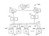
图6是图1所示的配电系统的网络部分的简化框图;Figure 6 is a simplified block diagram of the network portion of the power distribution system shown in Figure 1;
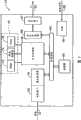
图7是使用在图6所示的配电系统的网络部分中的硬件时钟的代表性实施例的示意框图;7 is a schematic block diagram of a representative embodiment of a hardware clock for use in the network portion of the power distribution system shown in FIG. 6;
图8是示出了用于同步图6所示的多台冗余计算机的代表性过程的流程图;及FIG. 8 is a flowchart illustrating a representative process for synchronizing the multiple redundant computers shown in FIG. 6; and
图9是示出了用于同步图6所示的多台冗余计算机的过程的代表性实施例的数据流程图。FIG. 9 is a data flow diagram illustrating a representative embodiment of a process for synchronizing the multiple redundant computers shown in FIG. 6 .
具体实施方式Detailed ways
此处描述的称作系统数据捕获的方法和装置,描述了用于数据捕获系统收集的数据的有条件记录,显示或处理的装置。在一个实施例中,该方法以实时数据捕获模式运行。在另一个实施例中,该方法还应用于非实时系统中。当与断路器控制和保护系统一起使用时,系统数据捕获使得系统数据进行离线分析。另外,系统数据捕获有助于从整个系统收集的数据分析,如,电流和电压测量,以及断路器状态,从而有助于识别多种故障类型,并且在合理故障和损坏性跳闸之间进行区分。The methods and apparatus described herein, referred to as system data capture, describe means for conditional recording, display or processing of data collected by a data capture system. In one embodiment, the method operates in a real-time data capture mode. In another embodiment, the method is also applied in non-real-time systems. When used with circuit breaker control and protection systems, system data capture enables offline analysis of system data. In addition, system data capture facilitates the analysis of data collected from the entire system, such as current and voltage measurements, and circuit breaker status, thereby helping to identify multiple fault types and differentiate between legitimate faults and damaging trips .
图1示出了例如由工业企业使用的配电系统10的代表性示意图。在代表性实施例中,系统10包括至少一个主馈电系统12,配电总线14,多个电力电路开关或断流器,这里也称作断路器(CB)16,以及至少一个负载18,该负载例如但不局限于电动机,焊接机,计算机,加热器,照明设备,和/或其他电气设备。Figure 1 shows a representative schematic diagram of a
使用中,将电力从能源(未示出)供给主馈电系统12,即,例如开关板。该能源诸如但并不局限于从例如核反应堆,烧煤锅炉,燃气轮发电机以及柴油发电机获得动力的蒸汽涡轮机。供给主馈电系统12的电力使用断路器16分成多个支路,断路器16将电力提供给工业企业中的各种负载18上。另外,在各支路中提供断路器16以有助于保护设备,即,负载18,该负载18连接在各支路中。此外,这是因为可将特殊负载18通电或者断电而不影响其他负载18,因此断路器16有助于使设备故障达到最小,从而增加效率,以及减小操作和制造成本。In use, electrical power is supplied from an energy source (not shown) to the
配电系统10包括断路器控制保护系统19,控制保护系统19包括多个节点电子单元20,并且每个节点电子单元20电连接到数字网络22上。断路器控制保护系统19还包括至少一个中央控制处理单元(CCPU)24,该中央控制处理单元24通过开关23电连接到数字网络22上,该开关23例如但并不局限于以太网(Ethernet)开关23。在使用中,每个单独的节点电子单元20电连接到各自的断路器16上,这样CCPU24通过数字网络22并通过相应的节点电子单元20电连接到每个断路器16上。The
在代表性实施例中,数字网络22为快速以太网(Fast Ethernet)协议网络。在另一实施例中,数字网络22包括,例如,至少一个局域网(LAN)或广域网(WAN),拨号连接(dial-in-connection),电缆调制解调器,以及专用高速ISDN线。数字网络22还包括能互连到Internet上的任何设备,这些设备包括基于网络的电话机,个人数字助理(PDA),或其他基于网络的连接设备。值得注意的是数字网络22网络可基于IEEE 802.3(u)及其后继标准(successor)的未来修改进行升级。还应该注意的是数字网络22构造成例如星形拓扑。In a representative embodiment,
在一个实施例中,CCPU24是计算机,并包括设备26,例如软盘驱动器或者CD-ROM驱动器,从而有助于读取来自计算机可读媒介28的指令和/或数据,计算机可读媒介28如软盘或CD-ROM。在另一个实施例中,CCPU24执行存储在固件(未示出)中的指令。将CCPU24进行编程以实现在此描述的功能,但其他可编程电路可同样进行编程。因此,如此处所使用的,术语计算机并不局限于现有技术中称作计算机的那些集成电路,而是广泛地指计算机,处理器,微控制器,微机,可编程逻辑控制器,专用集成电路及其他可编程电路。另外,尽管描述在配电设备中,也可考虑本发明对包括工业系统的所有配电系统产生有益之处,例如,但不局限于安装在办公楼中的配电系统。In one embodiment, CCPU 24 is a computer and includes a
图2是示出了与配电系统10(示于图1)并尤其与断路器控制保护系统19(示于图1)使用的节点配电系统29的代表性示意图。节点配电系统29包括电源30,该电源30通过节点配电总线32电连接到节点电子单元20上。在代表性实施例中,电源30是不间断电源(UPS)。在一个实施例中,电源30接收来自配电系统10的电能并且然后将该电能通过节点配电总线32分配给节点电子单元20。在可替换实施例中,不将电能供给电源30,而是,电源30采用内部电源将电能提供给节点电子单元20,该内部电源例如但不局限于多个电池(未示出)。在另一个可替换实施例中,节点电子单元20由从电流传感器82和/或电压传感器84得到的二次电流提供电能。在该实施例中,断路器控制保护系统19不包括节点配电系统29,电源30或节点配电总线32。FIG. 2 is a representative schematic diagram illustrating nodal
图3是CCPU24的代表性示意图。CCPU24包括至少一个存储器装置40,该存储器装置例如但不局限于只读存储器(ROM)42,快速存储器44,和/或随机存取存储器(RAM)46。CCPU24还包括中央处理器单元(CPU)48,该中央处理器单元48电连接到至少一个存储器装置40上,还连接到内部总线50,通信接口52以及通信处理器54上。在代表性实施例中,CCPU24是印刷电路板,并且包括电源56,从而提供电能给印刷电路板上的多个设备。FIG. 3 is a representative schematic diagram of CCPU 24 . CCPU 24 includes at least one
此外,在代表性实施例中,内部总线50包括地址总线,数据总线,以及控制总线。在使用中,地址总线构造成使CPU48对多个内部存储器位置或输入/输出接口进行访问,该输入/输出接口例如但不局限于通过通信处理器54的通信接口52,以及通过网关处理器58的网关接口57。该数据总线构造成在CPU48和至少一个输入/输出之间发送指令和/或数据,并且控制总线构造成在多个设备之间发送信号从而有助于确保这些设备同步运行。在代表性实施例中,内部总线50是双向总线,这样使得信号可在内部总线50上的任何一个方向上发送。CCPU24还包括至少一个存储装置60,存储装置60构造成存储多个通过内部总线50发送的信息。Additionally, in the representative embodiment,
在使用中,网关接口57通过互联网链接62或内联网62与远程工作站(未示出)进行通信。在代表性实施例中,远程工作站是包括网络浏览器的个人计算机。尽管描述了单个工作站,此处描述的这种功能可在与网关接口57连接的多台个人计算机的一台上实现。例如,网关接口57可通信连接到各种单机上并连接到第三方上,单机包括本地操作机,第三方如通过ISP互联网连接的远程系统操作机。在该代表性实施例中的通信示出为通过互联网实现,然而,任何其他广域网(WAN)型的通信可在其他实施例中使用,其他实施例即,系统和方法不限于通过互联网实现。在一个实施例中,信息在网关接口57上接收并通过CCPU24和数字网络22发送给节点电子单元20。在另一个实施例中,从节点电子单元20发送的信息在通信接口52上接收并通过网关接口57发送给互联网62。In use,
图4是单个节点电子单元20的代表性示意图。在该代表性实施例中,节点电子单元20是远离CCPU24和断路器16安装的单一设备。在代表性实施例中,节点电子单元20与断路器16隔开,但靠近断路器16。在代表性实施例中,节点电子单元20是印刷电路板。FIG. 4 is a representative schematic diagram of a single
在一个实施例中,节点电子单元20接收从多个设备输入的信号,这些设备例如但并不局限于电流传感器82,电压传感器84,和/或断路器16。来自断路器16的状态信号包括与断路器的一个或多个状态相关的信号,例如但并不局限于辅助开关状态,以及弹簧装载开关状态。另外,节点电子单元20至少发送信号给断路器16以便控制断路器的一个或多个状态。In one embodiment,
在使用中,信号通过节点电子单元20发送到CCPU24和数字网络22上。节点电子单元20接收该信号并将数字消息打包,该数字消息包括信号和与节点电子单元20的质量(health)和状态相关的附加数据。该质量和状态数据可包括信息,该信息基于由内部诊断程序发现的问题和自测程序的状态,自测程序在节点电子单元20内本地运行。CCPU24使用一个或多个保护算法,监测算法以及其任意组合处理数字消息。响应数字消息的处理,CCPU24通过数字网络22将数字消息返还给节点电子单元20。在代表性实施例中,节点电子单元20通过响应从CCPU24接收的数字消息的信号来激励断路器16。在一个实施例中,响应仅由CCPU24发送的命令来激励断路器16,即,断路器16不受节点电子单元20本地控制,而是基于从网络22上的节点电子单元20接收的数字消息从CCPU24远程操作。In use, signals are sent via
图5是电连接到节点电子单元20上的断路器16的代表性示意图。在该代表性实施例中,断路器16包括开关组件,该开关组件包括可动和/或固定触头,抑弧装置,以及跳闸和操作机构。断路器16仅包括一个跳闸线圈100,闭合线圈102,辅助开关104,弹簧装载开关106,以及电动机108。断路器16不包括跳闸单元。断路器16的各种元件(如,跳闸线圈100,闭合线圈102,辅助开关104,弹簧装载开关106,电动机108)可由节点电子单元20提供电能。可替换地,断路器16可由从电流传感器82和/或电压传感器84得到的二次电流提供电能。FIG. 5 is a representative schematic diagram of the
断路器16与节点电子单元20通过线束电气通信,其中该线束可包括铜导线,通信管道,及其任一组合。电流传感器82,以及电压传感器84与节点电子单元20通过电缆进行电气通信,该电缆可包括铜导线,通信管道,及其任一组合。在代表性实施例中,断路器16是靠近节点电子单元20,电流传感器82,以及电压传感器84安装的单一设备。The
在使用中,将来自节点电子单元20的激励信号发送给断路器16,从而激励断路器16中的多个功能,例如,但并不局限于,操作跳闸线圈100,操作闭合线圈102,以及影响断路器闭锁特征。辅助开关104和操作弹簧装载开关106提供断路器参数的状态指示给节点电子单元20。电动机108构造成对工作弹簧进行再装载,当断路器16闭合后构造成为闭合弹簧(未示出)。值得注意的是电动机108可包括,例如,弹簧装载开关,能对跳闸弹簧进行再装载的螺线管和其他任一种电子-机械装置。为了闭合断路器16,闭合线圈102由来自激励电源模块(未示出)的关断信号通电。闭合线圈102激励闭合机构(未示出),该闭合机构将至少一个可动电气触头(未示出)连接到相应的固定电气触头(未示出)上。断路器16的闭合机构锁定在闭合位置,这样使得当闭合线圈102断电时断路器16保持闭合。当断路器16闭合时,辅助开关104的“a”触头也将闭合并且辅助开关104的“b”触头将打开。“a”和“b”触头的位置由节点电子单元20进行检测。为了打开断路器16,节点电子单元20向跳闸线圈(TC)100通电。TC100直接作用于断路器16上以释放保持断路器16闭合的锁定机构。当锁定机构释放时,断路器16将打开,打开辅助开关104的“a”触头并闭合辅助开关104的“b”触头。然后跳闸线圈100由节点电子单元20断电。在断路器16打开后,与由电动机108进行再装载的闭合弹簧一起,断路器16为下一个工作周期作准备。在代表性实施例中,每个节点电子单元20以一对一的对应关系连接到断路器16上。例如,每个节点电子单元20仅与一个断路器16直接通信。在可替换实施例中,节点电子单元20可与多个断路器16进行通信。In use, an energizing signal from the
图6是示于图1的配电系统10的网络部分600的简化框图。与图1所示的元件相同的图6中的元件在图6中采用与图1中相同的附图标记进行标记。因此,配电系统10的网络部分600包括多个节点电子单元20,每个节点电子单元20通过专门用于每个网络22的通信接口602通信连接到双冗余网络22上。在代表性实施例中,网络22是双冗余的。在可替换实施例中,网络22可冗余到由用户的需要所预定的水平上。每个网络22通信连接到网络开关23上,该网络开关通信连接到每个CCPU24上。每个CCPU24通信连接到硬件时钟604上。在代表性实施例中,每个CCPU24的并行端口用于接收来自硬件时钟604的输出信号。硬件时钟604可冗余到由用户的需要所预定的水平上。FIG. 6 is a simplified block diagram of
在操作上,硬件时钟604发送输出信号给所有的CCPU24,这些信号包括在正则区间上的中断脉冲。指定每个中断脉冲一个序号。在代表性实施例中,序号为16位长。在另一个实施例中,序号可在4位长和64位长之间。将每个中断脉冲和序号发送给每个CCPU24并行端口上,这样使得每个中断可由其单独的序号来连续识别。在每个中断脉冲上,硬件时钟604将序号递增从而使得新的连续的序号与每个接着产生的中断脉冲一起发送。当处理器48接收中断脉冲时,处理器48根据其程序指令服务于中断。在代表性实施例中,处理器48发送交叉基准(transreference)信号给网络22上所有的节点电子单元20,该交叉基准信号包括基准序号。为了保持基准号,处理器48在每次接收来自时钟604的输出信号时递增内部64位寄存器。In operation, the
另外,处理器48检测误差的引入中断脉冲。处理器48估计将要接收的下一个中断脉冲的时间。在代表性实施例中,监视定时器用于估计下一个输入信号或中断脉冲的期望时间。如果中断脉冲在期望时窗内接收,处理器48采用脉冲从而将它本身的时钟与硬件时钟604脉冲同步。如果中断脉冲在期望时窗之外,处理器48确定中断脉冲是否丢失,该丢失意味着中断脉冲没有由处理器48接收。脉冲的断续或不可靠接收可显示硬件时钟604和/或互连电缆的老化,并且可导致CCPU24和节点电子单元20失步。当中断脉冲丢失时,处理器48通过采用其内部时钟以确定丢失的中断脉冲的个数并由已经确定丢失的脉冲的个数递增基准号来试图恢复该基准号。通过这种方法,基准号保持与开始点相关的合适时间递增,该开始点与其他计时系统一致。在代表性实施例中,配电系统10事件可与采用该基准号的公用事业公司信号源一致。当处理器48确定硬件时钟406的中断脉冲故障,可采用稳定脉冲的可替换信号源。在代表性实施例中,当硬件时钟604故障时,处理器604时钟用作提供中断脉冲。在可替换实施例中,与网络22连接的一个CCPU24可互连到每个其他的处理器48上,从而当硬件时钟604故障时提供稳定脉冲的可替换信号源。In addition, the
节点电子单元20通过网络22接收来自CCPU24的交叉基准信号。每个节点电子单元20接收来自每个CCPU24的交叉基准信号。在代表性实施例中,网络22为双冗余,同样地,每个节点电子单元20接收包括辨别序号的两个交叉基准信号。为了将来自与节点电子单元20相关的多个传感器的数据的采集进行恰当的同步,节点电子单元20使用校正器功能程序以将它的时钟与引入的交叉基准信号同步。在一个实施例中,节点电子单元20误差检测期望定时输入的交叉基准信号。如果连接到网络的任何一个CCPU24正在发送期望时窗外的交叉基准信号,该CCPU24将作为潜在故障进行标记,并且将忽略来自该CCPU24的交叉基准信号。如果所有的CCPU24正在发送处于期望时窗内的交叉基准信号,节点电子单元20确定校正器程序以将节点电子单元20的时钟与CCPU24的时钟同步。在代表性实施例中,节点电子单元20采用将节点电子单元的时钟与其时钟同步的预定优选CCPU24。只要优选CCPU24发送在期望时窗内的交叉基准信号,节点电子单元20将使其时钟与该优先CCPU时钟同步。如果主CCPU24时钟发送期望时窗外的交叉基准信号,基于优先权的顺序,节点电子单元20可转换到与预定CCPU24同步,直到该优选CCPU24返回到发送在期望时窗内的交叉基准信号为止。在可替换实施例中,节点电子单元20将接收来自每个CCPU24的对应交叉基准信号的时间进行平均,并使其时钟与该平均值同步。注意,节点电子单元20采用与软件锁相环结合的交叉基准信号以调节节点电子单元时钟与CCPU24同步。
图7是硬件时钟604的代表性实施例的示意框图,该硬件时钟使用在图6所示的配电系统10的网络部分600中。在代表性实施例中,硬件时钟604包括晶体振荡器606,该晶体振荡器电连接到分频器电路608上。分频器电路608的输出连接到现场可编程门阵列(FPGA)装置610的输入上。FPGA610的输出连接到三态缓冲器612上。缓冲器612的输出连接到并行端口总线上,该并行端口总线连接到与配电系统10连接的每个CCPU24的并行端口上。FIG. 7 is a schematic block diagram of a representative embodiment of a
在使用中,FPGA608用作将从晶体振荡器606得到的时钟脉冲分成中断信号的期望频率。在代表性实施例中,晶体振荡器606工作在近1.832MHz的频率上。分频器608将振荡器606的频率向下分成近4.0kHz。FPGA608也用作得到8或16位的序号。在代表性实施例中,中断信号,低/高字节信号,以及2x8位序号(一次给1个字节的16位值)由所有CCPU24的并行端口读取。In use,
图8是示出了用于同步图6所示的多台冗余计算机的代表性过程的流程图800。在配电系统10上运行的每个CCPU24通过它的每个并行端口从硬件时钟604接收802中断脉冲流。尽管中断脉冲描述为通过每个并行接口由每个CCPU24接收,但是每个CCPU24可通过任何一个方便的端口和/或硬件时钟604的硬件连接接收中断脉冲。CCPU24还接收804与每个脉冲相关的序号。该序号由硬件时钟604产生。在代表性实施例中,序号为在8位总线上以两个字节发送给所有的CCPU24的16位号。FIG. 8 is a flowchart 800 illustrating a representative process for synchronizing the multiple redundant computers shown in FIG. 6 . Each
每个中断脉冲使得每个CCPU处理器48读取由硬件时钟604提供的序号。该中断脉冲由处理器48用于控制所有内部计算的执行时钟。当接收每个中断时,处理器48发送804包括序号的输入信号给基准目标,该基准目标递增计算所接收的每个中断脉冲的内部基准号计数器并允许通过变换806输入信号到公知的时间基准而重建并与外部系统的数据一致。处理器48产生多点传送消息,该多点传送消息是通过网络22发送给所有的节点电子单元20的广播通信。每个消息包括交叉基准信号和与该脉冲相关的序号。Each interrupt pulse causes each
在网络22上运行的每个节点电子单元20接收来自网络22上运行的每个CCPU24的多点传送消息。每个节点电子单元20使用预定程序以判断出消息定时之间的任何区别。在一个实施例中,节点电子单元20将一个CCPU24认为是优选的,并且节点电子单元20使用来自该CCPU24的交叉基准信号和序号,直到节点电子单元20确定该CCPU24是不可靠的。在另一个实施例中,节点电子单元20可使用平均技术或表决技术来确定哪个CCPU交叉基准信号为所使用的最正确的脉冲。Each
节点电子单元20采用交叉基准信号和序号将来自每个传感器的收集数据进行同步,从而采样传感器和内部电子元件寄存器,使得配电系统10的状态可在CCPU24中精确重建。在大配电系统10中,每个节点电子单元20可在不同的实时采样传感器和数据寄存器,这是因为在节点电子单元20之间系统中固有时间滞后。采样许多电气参数将产生不精确的结果,但当每一个所采样的参数与交叉基准信号和序号相关时,CCPU24可解决当每个采样进行时实时上的改变,其中电气参数相对甚至很小区别的实时上的时间经常改变。The
节点电子单元20包括软件锁相环,该软件锁相环使用广播消息、交叉基准信号和序号,从而将其时钟与CCPU时钟同步。The
每个CCPU24进行编程,以实现输入的中断脉冲的误差检测。每个CCPU处理器48确定何时期望从硬件时钟604到达的下一个中断信号的估计时窗。如果下一个中断脉冲在期望窗内接收,处理器48假定硬件时钟604和互连电缆正在正确运行,不进行校正行为。如果至少一个中断脉冲在期望窗外到达,处理器48执行确定校正行为的误差处理程序,从而保持配电系统10同步。在代表性实施例中,处理器48在激励该误差处理程序之前等待四个丢失的脉冲。在另一个实施例中,周期处理器48等待从零丢失脉冲(处理器唯一地采用脉冲的可替换信号源)到最大数量所配置的用户,最大数量显示处理器48从不使用脉冲的可替换信号源。在一个实施例中,当检测中断脉冲已经停止到达时,切换到中断脉冲的可替换信号源,如处理器时钟,可替换CCPU处理器时钟,或另一个可替换脉冲源。处理器48然后估计多少个脉冲丢失并递增基准号寄存器,通过该基准号从而将该基准号寄存器返回到尽可能接近其恰当时刻。当中断脉冲恢复时,处理器48执行程序从而恢复同步到硬件时钟604。Each
图9是示出了过程900的代表性实施例的数据流程图,该过程用于同步图6所示的多台冗余计算机。依据预定的需求,多个CCPU24可包括在配电系统10中。每个CCPU24包括类似的数据结构,但仅仅是包括在一个CCPU中的数据结构在此进行描述。另外,类似的数据流程图在每个节点电子单元20中实施,数据流程图以此处描述的类似方式运行。CCPU24从外部定时源904接收外部输入定时信号902,该外部定时源904位于远离CCPU24的地方。此处使用的定时信号指的是定时时钟脉冲以及信号,该信号的到达显示定时事件并且包括消息中的定时部分。例如,定时信号可为64位长的消息,该64位长包括显示序号的第一组位,以及显示相关时间戳(times tamp)的第二组位。接收定时信号的元件或数据结构可记录接收定时信号的本地时间,分析定时信号内的信息,以及基于在定时信号中接收的定时信息来鉴别它本身的时钟运行。另外,元件或数据结构可从多个信号源接收多个定时信号,并使用一个算法来确定它本身的时钟或其它接收输入信号的时钟的质量及状态。在代表性实施例中,外部定时源904可包括硬件时钟,另一个CCPU24,以及系统10外部的辅助电源,在硬件时钟中输入信号902可包括6位长到16位长的序号。FIG. 9 is a data flow diagram illustrating a representative embodiment of a
CCPU24还接收来自内部定时源908的内部定时信号906,该内部定时源位于CCPU24内部,例如,但不局限于处理器时钟。至少一个选择器910的每一个接收输入定时信号902和906,以及多个选择参数912。选择参数912由选择器910使用,以确定输入信号902和906的哪个用作产生输出信号的原始信号源。在代表性实施例中,选择参数912可用于确定电源904和908的优先顺序,以及所使用的标准,该标准用于确定期望时窗内的输入信号902和906的存在,确定输入信号902和906的丢失,确定无效输入信号902和906,以及确定噪声输入信号902和906。为了确定期望时窗,选择器910可采用监视定时器。如果选择器910确定输入信号902和906中的一个不满足由选择参数912所指示的标准,选择器910可产生并发送校正发生器信号916,该信号916输入到校正器函数918中。校正器函数918基于校正发生器信号916和输入信号k922确定定时误差信号920。输入信号k922与选择参数912相关,使得选择器910和校正器函数918协调运行。误差信号920发送到信号源902和906中与输入信号误差相关的单独一个信号源上。每个单独的信号源902和906基于误差信号920调节其单独的输入信号。
输入信号902和906还由基准目标924进行接收,该基准目标基于输入信号902和906以及内部算法将输入信号902和906转换为基准信号,该内部算法将基准维持在绝对时间上。例如,输入信号902和906可包括6位长的序号。每一个输入信号902和906可在例如200和60微秒的周期到达。随着每个输入信号902和906中的每个序号从每个在前输入信号902和906的序号递增,序号将在相对短的时间周期内翻转。维持唯一的定时系统的一个方案是增加每个序号使用的位数。该方案具有的缺点是增加了输入信号902和906的长度。在代表性实施例中,序号是6位长。在可替换实施例中,序号为16位长。基准目标924接收输入信号902和906,并将它们转换为交叉基准信号928,该交叉基准信号928包括基准序号,该基准序号包括足够的位数,使得维持唯一的时间基准。在代表性实施例中,基准序号是64位长。交叉基准信号928在CCPU24内本地使用以驱动本地处理930以及在网络22上发送到节点电子单元20,在节点电子单元20中交叉基准信号928用作每个节点电子单元20定时处理的输入信号。The input signals 902 and 906 are also received by a
上述的配电多台同步冗余计算机方法和系统是节省成本的并且可靠性高。每个系统包括中央控制处理单元(CCPU)和网络设备,从而有助于保护一组开关装置。多台冗余计算机采用具有各种备份的外部硬件时钟进行同步,这些备份用于在设备故障和维护期间保持同步。每个断路器本地的设备监测来自传感器的电压和电流信号,该传感器位于每个断路器附近。CCPU从高速网络上的所有设备接收所有的监测信号。为了确保在一个节点电子单元上测得的参数与在另一个节点电子单元上测得的参数一致,配电系统内所有的CCPU和所有的节点电子单元与初始时钟进行同步。然后CCPU可基于全局电压和电流信号对每个断路器节点电子单元执行保护和优化算法。因此,配电系统硬件时钟有助于以节约成本和可靠的方式运行的电源系统的保护和优化。The above-mentioned method and system for distributing multiple synchronous redundant computers is cost-effective and highly reliable. Each system includes a central control processing unit (CCPU) and network equipment, thereby helping to protect a group of switchgear. Multiple redundant computers are synchronized using external hardware clocks with various backups used to maintain synchronization during equipment failures and maintenance. Devices local to each circuit breaker monitor voltage and current signals from sensors located near each circuit breaker. The CCPU receives all monitoring signals from all devices on the high-speed network. In order to ensure that the parameters measured on one node electronic unit are consistent with those measured on another node electronic unit, all CCPUs and all node electronic units in the power distribution system are synchronized with the initial clock. The CCPU can then execute protection and optimization algorithms for each circuit breaker node electronic unit based on the global voltage and current signals. Therefore, a power distribution system hardware clock helps in the protection and optimization of a power system that operates in a cost-effective and reliable manner.
配电系统元件的代表性实施例在上面进行了详细描述。但这些元件并不局限于在此描述的特定实施例,而是,每个系统的元件可单独并与在此描述的其他元件分开使用。每个配电系统元件也可与其他配电系统元件结合使用。Representative embodiments of power distribution system components are described in detail above. However, these elements are not limited to the specific embodiments described herein, but rather, elements of each system may be used individually and separately from other elements described herein. Each power distribution system element can also be used in combination with other power distribution system elements.
尽管本发明已经依据各种特定实施例进行描述,本领域的技术人员知道本发明可用落入权利要求的精神和范围内的改变来实施。While the invention has been described in terms of various specific embodiments, those skilled in the art will recognize that the invention can be practiced with modification within the spirit and scope of the claims.
Claims (60)
Translated fromChineseApplications Claiming Priority (4)
| Application Number | Priority Date | Filing Date | Title |
|---|---|---|---|
| US35954402P | 2002-02-25 | 2002-02-25 | |
| US60/359,544 | 2002-02-25 | ||
| US43815903P | 2003-01-06 | 2003-01-06 | |
| US60/438,159 | 2003-01-06 |
Publications (2)
| Publication Number | Publication Date |
|---|---|
| CN1639654A CN1639654A (en) | 2005-07-13 |
| CN100468279Ctrue CN100468279C (en) | 2009-03-11 |
Family
ID=27767578
Family Applications (8)
| Application Number | Title | Priority Date | Filing Date |
|---|---|---|---|
| CNB038046148AExpired - LifetimeCN100511905C (en) | 2002-02-25 | 2003-02-25 | Method and apparatus for ground fault protection |
| CNB038046024AExpired - LifetimeCN100559309C (en) | 2002-02-25 | 2003-02-25 | Protection systems for power distribution systems |
| CN038046008AExpired - LifetimeCN1639649B (en) | 2002-02-25 | 2003-02-25 | Method and system for conditionally triggered system data capture |
| CNB038046105AExpired - LifetimeCN100354777C (en) | 2002-02-25 | 2003-02-25 | Integrated protection, monitoring and control system |
| CN038046075AExpired - LifetimeCN1639939B (en) | 2002-02-25 | 2003-02-25 | Circuit protection method, circuit protection system and power distribution system |
| CN03804613XAExpired - LifetimeCN1639651B (en) | 2002-02-25 | 2003-02-25 | Data sampling and transmission module for power distribution system |
| CN2008100989969AExpired - LifetimeCN101291081B (en) | 2002-02-25 | 2003-02-25 | Data sampling and transmission module for power distribution system |
| CNB038046040AExpired - LifetimeCN100468279C (en) | 2002-02-25 | 2003-02-25 | Obtaining external clocks for multiple synchronous computers |
Family Applications Before (7)
| Application Number | Title | Priority Date | Filing Date |
|---|---|---|---|
| CNB038046148AExpired - LifetimeCN100511905C (en) | 2002-02-25 | 2003-02-25 | Method and apparatus for ground fault protection |
| CNB038046024AExpired - LifetimeCN100559309C (en) | 2002-02-25 | 2003-02-25 | Protection systems for power distribution systems |
| CN038046008AExpired - LifetimeCN1639649B (en) | 2002-02-25 | 2003-02-25 | Method and system for conditionally triggered system data capture |
| CNB038046105AExpired - LifetimeCN100354777C (en) | 2002-02-25 | 2003-02-25 | Integrated protection, monitoring and control system |
| CN038046075AExpired - LifetimeCN1639939B (en) | 2002-02-25 | 2003-02-25 | Circuit protection method, circuit protection system and power distribution system |
| CN03804613XAExpired - LifetimeCN1639651B (en) | 2002-02-25 | 2003-02-25 | Data sampling and transmission module for power distribution system |
| CN2008100989969AExpired - LifetimeCN101291081B (en) | 2002-02-25 | 2003-02-25 | Data sampling and transmission module for power distribution system |
Country Status (5)
| Country | Link |
|---|---|
| US (16) | US20030225481A1 (en) |
| EP (7) | EP1479147B1 (en) |
| CN (8) | CN100511905C (en) |
| AU (18) | AU2003228219A1 (en) |
| WO (18) | WO2003073179A1 (en) |
Families Citing this family (504)
| Publication number | Priority date | Publication date | Assignee | Title |
|---|---|---|---|---|
| US20010032278A1 (en) | 1997-10-07 | 2001-10-18 | Brown Stephen J. | Remote generation and distribution of command programs for programmable devices |
| US7904194B2 (en) | 2001-02-09 | 2011-03-08 | Roy-G-Biv Corporation | Event management systems and methods for motion control systems |
| DE10119624A1 (en)* | 2001-04-20 | 2002-11-21 | Aloys Wobben | Operating wind energy plant involves regulating power delivered from generator to electrical load, especially of electrical network, depending on current delivered to the load |
| SK287212B6 (en) | 2001-04-20 | 2010-03-08 | Aloys Wobben | Method of operating a wind power installation and wind power plant |
| JP3693337B2 (en)* | 2001-09-10 | 2005-09-07 | デンセイ・ラムダ株式会社 | Power system wiring diagram creation system, and power supply equipment and program used therefor |
| US20030212473A1 (en)* | 2002-02-25 | 2003-11-13 | General Electric Company | Processing system for a power distribution system |
| WO2003073179A1 (en)* | 2002-02-25 | 2003-09-04 | General Electric Company | Method and apparatus for node electronics unit architecture |
| US7747356B2 (en)* | 2002-02-25 | 2010-06-29 | General Electric Company | Integrated protection, monitoring, and control system |
| US8266271B2 (en)* | 2002-09-10 | 2012-09-11 | Jds Uniphase Corporation | Propagation of signals between devices for triggering capture of network data |
| WO2004040731A1 (en)* | 2002-10-25 | 2004-05-13 | S & C Electric Co. | Method and apparatus for control of an electric power system in response to circuit abnormalities |
| US7825536B2 (en)* | 2002-11-04 | 2010-11-02 | Raytheon Company | Intelligent power system |
| KR20050088107A (en)* | 2002-12-06 | 2005-09-01 | 일렉트릭 파워 리서치 인스티튜트 | Uninterruptible power supply and generator system |
| US20040153303A1 (en)* | 2002-12-30 | 2004-08-05 | Le Tang | Efficient process for time dependent network model in an energy market simulation system |
| US7986503B2 (en)* | 2003-01-06 | 2011-07-26 | General Electric Company | Circuit protection system |
| JP3954511B2 (en)* | 2003-03-14 | 2007-08-08 | 株式会社東芝 | Power distribution system monitoring and control device |
| JP3851617B2 (en)* | 2003-05-27 | 2006-11-29 | ファナック株式会社 | Motor drive device |
| US7827248B2 (en)* | 2003-06-13 | 2010-11-02 | Randy Oyadomari | Discovery and self-organization of topology in multi-chassis systems |
| DE112004001617D2 (en)* | 2003-06-24 | 2006-05-11 | Bosch Gmbh Robert | Method for checking the security and reliability of software-based electronic systems |
| US8190722B2 (en)* | 2003-06-30 | 2012-05-29 | Randy Oyadomari | Synchronization of timestamps to compensate for communication latency between devices |
| US20060064503A1 (en) | 2003-09-25 | 2006-03-23 | Brown David W | Data routing systems and methods |
| US8027349B2 (en) | 2003-09-25 | 2011-09-27 | Roy-G-Biv Corporation | Database event driven motion systems |
| JP2007510394A (en)* | 2003-10-24 | 2007-04-19 | スクエア・ディー・カンパニー | Intelligent power management control system |
| DE10349906A1 (en)* | 2003-10-25 | 2005-05-25 | Abb Patent Gmbh | control unit |
| ES2243120B1 (en)* | 2003-11-03 | 2007-03-16 | Hitea-Hidraulica E Integracion De Tecnologias De Automatizacion, S.L. | LINE SUPERVISOR FOR NETWORK OF REMOTE CONTROL STATIONS INTERCONNECTED THROUGH ELECTRICAL CABLE. |
| RU2270469C2 (en)* | 2004-03-11 | 2006-02-20 | Олег Алексеевич Суханов | System for controlling modes of electric energy based systems |
| US7203040B2 (en)* | 2004-03-31 | 2007-04-10 | Gaton Corporation | Method and circuit breaker for reducing arc flash during maintenance in a low voltage power circuit |
| US20050243491A1 (en)* | 2004-04-28 | 2005-11-03 | James Tanis | Multi-function power monitor and circuit protector |
| DE102004021380A1 (en)* | 2004-04-30 | 2005-12-01 | Siemens Ag | Device for power supply |
| US7363195B2 (en)* | 2004-07-07 | 2008-04-22 | Sensarray Corporation | Methods of configuring a sensor network |
| US20060015611A1 (en)* | 2004-07-16 | 2006-01-19 | Sbc Knowledge Ventures, Lp | System and method for proactively recognizing an inadequate network connection |
| DE102004039810A1 (en)* | 2004-08-11 | 2006-02-23 | MERLINAMO Vermögensverwaltung GmbH | Device for controlling the power supply of at least one data-technical device |
| DE112004002933B4 (en)* | 2004-08-11 | 2011-01-20 | Netchilli Gmbh | Device for controlling the flow of energy between a power supply network and an electrical device connected thereto |
| US20060103548A1 (en)* | 2004-11-01 | 2006-05-18 | Centerpoint Energy, Inc. | Current sensing bar |
| US7808128B1 (en)* | 2004-11-12 | 2010-10-05 | Dgi Creations, Llc | Remote monitoring of control decisions for network protectors |
| DE602005016837D1 (en)* | 2004-11-18 | 2009-11-05 | Powersense As | EFFECT SENSORS |
| US8621117B2 (en)* | 2004-11-30 | 2013-12-31 | Abb Research Ltd. | Intelligent configuration system for power distribution feeder reclosers and switches |
| US7826932B2 (en)* | 2004-12-10 | 2010-11-02 | General Electric Company | Systems and methods for updating graphical representations on multiple interface devices |
| US20060146462A1 (en)* | 2005-01-04 | 2006-07-06 | Andy Hines | Enhanced safety stop device for pools and spas |
| ITBO20050023A1 (en)* | 2005-01-19 | 2006-07-20 | Raffaelli Marcello | METHOD FOR DETECTION AND LOCALIZATION OF A GROUND FAULT IN AN ELECTRIC LINE |
| US20060218267A1 (en)* | 2005-03-24 | 2006-09-28 | Khan Irfan Z | Network, system, and application monitoring |
| US20070061460A1 (en)* | 2005-03-24 | 2007-03-15 | Jumpnode Systems,Llc | Remote access |
| US20060241881A1 (en)* | 2005-03-30 | 2006-10-26 | Gasperi Michael L | Networked power line parameter analysis method and system |
| US7525782B1 (en)* | 2005-03-31 | 2009-04-28 | The United States Of America As Represented By The United States Department Of Energy | Adaptive protection algorithm and system |
| US7571028B2 (en)* | 2005-04-19 | 2009-08-04 | Genscape Intangible Holding, Inc. | Method and system for AC power grid monitoring |
| JP4549921B2 (en)* | 2005-04-28 | 2010-09-22 | 富士通株式会社 | Laying net, laying net communication node and laying net communication method |
| US7535686B2 (en)* | 2005-06-08 | 2009-05-19 | General Electric Company | Control of circuit breakers in a multi-phase power system |
| US8250163B2 (en)* | 2005-06-09 | 2012-08-21 | Whirlpool Corporation | Smart coupling device |
| EP1734636B1 (en)* | 2005-06-16 | 2013-05-29 | Adhoco AG | Switchbox |
| US7272518B2 (en)* | 2005-07-01 | 2007-09-18 | Square D Company | Automated hierarchy classification in utility monitoring systems |
| US8024390B2 (en)* | 2005-07-01 | 2011-09-20 | Schneider Electric USA, Inc. | Automated data alignment based upon indirect device relationships |
| US7684441B2 (en)* | 2005-07-01 | 2010-03-23 | Bickel Jon A | Automated precision alignment of data in a utility monitoring system |
| US7349815B2 (en)* | 2005-07-01 | 2008-03-25 | Square D Company | Automated integration of data in utility monitoring systems |
| CA2622288C (en)* | 2005-09-12 | 2015-06-30 | Siemens Energy & Automation, Inc. | Panel layout for an integrated power distribution system |
| US7714735B2 (en) | 2005-09-13 | 2010-05-11 | Daniel Rockwell | Monitoring electrical assets for fault and efficiency correction |
| ITTO20050712A1 (en)* | 2005-10-07 | 2007-04-08 | Ansaldo Ricerche S P A | ELECTRICITY GENERATION SYSTEM |
| ITTO20050711A1 (en)* | 2005-10-07 | 2007-04-08 | Ansaldo Ricerche S P A | RECONFIGURABLE ENERGY DISTRIBUTION NETWORK |
| US7301739B2 (en)* | 2005-10-12 | 2007-11-27 | Chevron U.S.A. Inc. | Ground-fault circuit-interrupter system for three-phase electrical power systems |
| US8032766B2 (en)* | 2005-11-14 | 2011-10-04 | Zippy Technology Corp. | Machine boot up protection structure for parallel power supply equipment |
| US8032260B2 (en)* | 2005-11-30 | 2011-10-04 | General Electric Company | Method and system for controlling a power distribution system |
| US20070159746A1 (en)* | 2005-12-30 | 2007-07-12 | General Electric Company | Centrally controlled protection systems having reduced energy let-through mode |
| US7402999B2 (en)* | 2005-11-30 | 2008-07-22 | General Electric Company | Pulsed eddy current pipeline inspection system and method |
| US20110172840A1 (en)* | 2005-11-30 | 2011-07-14 | Radoslaw Narel | Centrally controlled protection system having reduced energy let-through mode |
| EP1795481A1 (en)* | 2005-12-07 | 2007-06-13 | Inventio Ag | Installation system and method for elevators |
| US7623043B2 (en)* | 2005-12-19 | 2009-11-24 | General Electric Company | Method and system for metering consumption of energy |
| WO2007070955A1 (en) | 2005-12-20 | 2007-06-28 | Bradley Leighton Ross | Power distribution system with individually isolatable functional zones |
| AU2008100118B4 (en)* | 2005-12-20 | 2008-04-10 | Bradley Leighton Ross | Power distribution system with individually isolatable functional zones |
| US7463989B2 (en) | 2005-12-21 | 2008-12-09 | General Electric Company | Waveform recorder apparatus and method |
| US7430482B2 (en) | 2005-12-21 | 2008-09-30 | General Electric Company | Waveform recorder apparatus and method |
| US7554796B2 (en) | 2006-01-20 | 2009-06-30 | Adc Telecommunications, Inc. | Modular power distribution system and methods |
| EP1982396B1 (en)* | 2006-02-06 | 2014-03-19 | S & C Electric Company | Coordinated fault protection system |
| US7369921B2 (en)* | 2006-02-10 | 2008-05-06 | Northrop Grumman Corporation | Power distribution expert system |
| US8036872B2 (en)* | 2006-03-10 | 2011-10-11 | Edsa Micro Corporation | Systems and methods for performing automatic real-time harmonics analyses for use in real-time power analytics of an electrical power distribution system |
| WO2007095585A2 (en)* | 2006-02-14 | 2007-08-23 | Edsa Micro Corporation | Systems and methods for real-time system monitoring and predictive analysis |
| US20160246905A1 (en) | 2006-02-14 | 2016-08-25 | Power Analytics Corporation | Method For Predicting Arc Flash Energy And PPE Category Within A Real-Time Monitoring System |
| US20170046458A1 (en) | 2006-02-14 | 2017-02-16 | Power Analytics Corporation | Systems and methods for real-time dc microgrid power analytics for mission-critical power systems |
| US8959006B2 (en)* | 2006-03-10 | 2015-02-17 | Power Analytics Corporation | Systems and methods for automatic real-time capacity assessment for use in real-time power analytics of an electrical power distribution system |
| US9092593B2 (en) | 2007-09-25 | 2015-07-28 | Power Analytics Corporation | Systems and methods for intuitive modeling of complex networks in a digital environment |
| US7729808B2 (en)* | 2006-03-10 | 2010-06-01 | Edsa Micro Corporation | System for comparing real-time data and modeling engine data to predict arc flash events |
| US9557723B2 (en) | 2006-07-19 | 2017-01-31 | Power Analytics Corporation | Real-time predictive systems for intelligent energy monitoring and management of electrical power networks |
| US20210397768A1 (en)* | 2006-02-14 | 2021-12-23 | Power Analytics Corporation | Method For Predicting Arc Flash Energy And PPE Category Within A Real-Time Monitoring System |
| US7539550B2 (en)* | 2006-02-23 | 2009-05-26 | Rockwell Automation Technologies, Inc. | Safety versus availability graphical user interface |
| US7657814B2 (en)* | 2006-02-23 | 2010-02-02 | Rockwell Automation Technologies, Inc. | Optimizing availability and safety by reconfiguring and auto-adjusting redundancy |
| US7646575B2 (en)* | 2006-03-09 | 2010-01-12 | Utility Relay Co., Ltd. | Manually-controlled arc flash energy reduction system and method for circuit breaker trip units |
| US7840396B2 (en)* | 2006-03-10 | 2010-11-23 | Edsa Micro Corporation | Systems and methods for determining protective device clearing times used for providing real-time predictions about arc flash events |
| WO2007106430A2 (en)* | 2006-03-10 | 2007-09-20 | Edsa Micro Corporation | Systems and methods for real- time protective device evaluation in an electrical power distribution system |
| US8112247B2 (en)* | 2006-03-24 | 2012-02-07 | International Business Machines Corporation | Resource adaptive spectrum estimation of streaming data |
| US8126685B2 (en)* | 2006-04-12 | 2012-02-28 | Edsa Micro Corporation | Automatic real-time optimization and intelligent control of electrical power distribution and transmission systems |
| US7693608B2 (en)* | 2006-04-12 | 2010-04-06 | Edsa Micro Corporation | Systems and methods for alarm filtering and management within a real-time data acquisition and monitoring environment |
| FR2900637B1 (en)* | 2006-05-04 | 2009-02-13 | Airbus France Sas | DEVICE AND METHOD FOR MANAGING THE ACTIVATION OR DEACTIVATION OF ELECTRICAL POWER SUPPLIES IN ELECTRICAL SYSTEMS ON BOARD AN AIRCRAFT |
| US20070263649A1 (en)* | 2006-05-12 | 2007-11-15 | Genti Cuni | Network diagnostic systems and methods for capturing network messages |
| US7280931B1 (en)* | 2006-05-18 | 2007-10-09 | International Business Machines Corporation | Method and system for calibrating an electrical device |
| US20070271383A1 (en)* | 2006-05-18 | 2007-11-22 | International Business Machines Corporation | Method and system for managing an electrical device over a power delivery network |
| US20070279068A1 (en)* | 2006-05-31 | 2007-12-06 | Harres Daniel N | Power diagnostic system and method |
| US7685447B2 (en)* | 2006-07-05 | 2010-03-23 | Eaton Corporation | Circuit interrupter and method modulating configurable processor clock to provide reduced current consumption |
| ATE474365T1 (en)* | 2006-08-16 | 2010-07-15 | Siemens Ag | ARRANGEMENT WITH AT LEAST ONE MEASURING DEVICE CONNECTED TO AN ENERGY TRANSMISSION NETWORK AND METHOD FOR OPERATING THE SAME |
| US7693607B2 (en)* | 2006-09-07 | 2010-04-06 | General Electric Company | Protection and control system for electric power networks with signal and command interfaces at the primary equipment |
| US7558651B2 (en)* | 2006-09-22 | 2009-07-07 | Siemens Energy & Automation, Inc. | Dynamic setup wizard in lighting control system commissioning |
| US8319372B2 (en)* | 2006-09-22 | 2012-11-27 | Siemens Industry, Inc. | EIB protocol in an integrated power distribution system |
| US7787223B2 (en)* | 2006-10-19 | 2010-08-31 | Siemens Industry, Inc. | Electronic breaker system |
| EP1956696B1 (en)* | 2006-10-20 | 2012-03-21 | ABB Technology AG | A MV or HV power distribution cubicle with integrated digital communication, and a multi-functional module for such a cubicle |
| US20100090542A1 (en)* | 2006-10-27 | 2010-04-15 | Outsmart Power Systems, Llc | Mapped Nodes In A Wire Network Providing Power/Communication & Load Identification |
| AU2007315385A1 (en)* | 2006-10-31 | 2008-05-08 | Linak A/S | A motor operator for switchgear for mains power distribution systems |
| US20080224546A1 (en)* | 2006-11-27 | 2008-09-18 | Teselle John Arthur | Method to analyze system reconfiguration for automated isolation of disturbances to the power distribution system |
| WO2008067299A2 (en)* | 2006-11-27 | 2008-06-05 | Firstenergy Corp. | Method and system for isolating disturbances to the power distribution system |
| WO2008065196A2 (en)* | 2006-11-30 | 2008-06-05 | North Sensor A/S | Faraday effect current sensor |
| US20080142486A1 (en)* | 2006-12-19 | 2008-06-19 | Nataniel Barbosa Vicente | Circuit breaker with adjustable arc-flash protection and wireless sensor and method of use |
| US7561393B2 (en)* | 2006-12-28 | 2009-07-14 | General Electric Company | Circuit protection system |
| US7599161B2 (en)* | 2006-12-29 | 2009-10-06 | General Electric Company | Relay device and corresponding method |
| KR100857393B1 (en) | 2006-12-29 | 2008-09-05 | 엘에스산전 주식회사 | Remote control device and method of air circuit breaker |
| US7542256B2 (en) | 2006-12-29 | 2009-06-02 | General Electric Company | Relay device and corresponding method |
| US20080167827A1 (en)* | 2007-01-05 | 2008-07-10 | Mcallister Sara C | Two-stage high impedance fault detection |
| US8350417B1 (en) | 2007-01-30 | 2013-01-08 | Sunpower Corporation | Method and apparatus for monitoring energy consumption of a customer structure |
| DE502008003097D1 (en)* | 2007-02-08 | 2011-05-19 | Siemens Ag | METHOD AND SYSTEM FOR DETERMINING THE RELIABILITY PARAMETERS OF A TECHNICAL SYSTEM |
| US7570471B2 (en)* | 2007-02-20 | 2009-08-04 | Utility Relay Company | Circuit breaker trip unit with zone selective interlock and system monitoring |
| DE102007010568A1 (en)* | 2007-02-23 | 2008-08-28 | Siemens Ag | Energy distribution device, in particular low-voltage power distribution device |
| US7751166B2 (en)* | 2007-03-16 | 2010-07-06 | Abb Technology Ag | Advanced feeder architecture with automated power restoration |
| US7805204B2 (en)* | 2007-03-21 | 2010-09-28 | Honeywell International Inc. | Integrated electrical power distribution system using common building blocks |
| US7929260B2 (en)* | 2007-03-30 | 2011-04-19 | General Electric Company | Arc flash elimination system, apparatus, and method |
| ITPR20070027A1 (en)* | 2007-04-11 | 2008-10-12 | Sanviti Elettrocostruzioni S R | MANAGEMENT DEVICE FOR AN ELECTRIC USER |
| US8081726B2 (en)* | 2007-05-10 | 2011-12-20 | Schneider Electric USA, Inc. | Method and apparatus for synchronizing data in utility system |
| GB0709042D0 (en)* | 2007-05-11 | 2007-06-20 | Deepstream Technologies Ltd | Method and apparatus for executing secondary functions on an electrical switchgear device |
| GB2449677A (en)* | 2007-06-01 | 2008-12-03 | Kevin Jones | A system for identifying a risk of fire in a power network |
| EP2101394A1 (en)* | 2008-03-10 | 2009-09-16 | ABB Research Ltd. | Distribution controller |
| US8207858B2 (en)* | 2007-08-07 | 2012-06-26 | Cooper Technologies Company | Monitoring systems and methods for ensuring a proper use of personal protective equipment for potential hazards presented to a person while servicing an electrical power system |
| ATE502460T1 (en)* | 2007-08-16 | 2011-04-15 | Nxp Bv | SYSTEM AND METHOD FOR PROVIDING ERROR DETECTION CAPABILITY |
| US9136711B2 (en)* | 2007-08-21 | 2015-09-15 | Electro Industries/Gauge Tech | System and method for synchronizing multiple generators with an electrical power distribution system |
| US8996183B2 (en) | 2007-08-28 | 2015-03-31 | Consert Inc. | System and method for estimating and providing dispatchable operating reserve energy capacity through use of active load management |
| US20100235008A1 (en)* | 2007-08-28 | 2010-09-16 | Forbes Jr Joseph W | System and method for determining carbon credits utilizing two-way devices that report power usage data |
| US8806239B2 (en) | 2007-08-28 | 2014-08-12 | Causam Energy, Inc. | System, method, and apparatus for actively managing consumption of electric power supplied by one or more electric power grid operators |
| US8890505B2 (en) | 2007-08-28 | 2014-11-18 | Causam Energy, Inc. | System and method for estimating and providing dispatchable operating reserve energy capacity through use of active load management |
| US9177323B2 (en) | 2007-08-28 | 2015-11-03 | Causam Energy, Inc. | Systems and methods for determining and utilizing customer energy profiles for load control for individual structures, devices, and aggregation of same |
| US9130402B2 (en) | 2007-08-28 | 2015-09-08 | Causam Energy, Inc. | System and method for generating and providing dispatchable operating reserve energy capacity through use of active load management |
| US8131403B2 (en)* | 2007-08-28 | 2012-03-06 | Consert, Inc. | System and method for determining and utilizing customer energy profiles for load control for individual structures, devices, and aggregation of same |
| US8542685B2 (en)* | 2007-08-28 | 2013-09-24 | Consert, Inc. | System and method for priority delivery of load management messages on IP-based networks |
| US8145361B2 (en)* | 2007-08-28 | 2012-03-27 | Consert, Inc. | System and method for manipulating controlled energy using devices to manage customer bills |
| US8527107B2 (en)* | 2007-08-28 | 2013-09-03 | Consert Inc. | Method and apparatus for effecting controlled restart of electrical servcie with a utility service area |
| US8700187B2 (en) | 2007-08-28 | 2014-04-15 | Consert Inc. | Method and apparatus for actively managing consumption of electric power supplied by one or more electric utilities |
| US8260470B2 (en)* | 2007-08-28 | 2012-09-04 | Consert, Inc. | System and method for selective disconnection of electrical service to end customers |
| US10295969B2 (en) | 2007-08-28 | 2019-05-21 | Causam Energy, Inc. | System and method for generating and providing dispatchable operating reserve energy capacity through use of active load management |
| US7715951B2 (en) | 2007-08-28 | 2010-05-11 | Consert, Inc. | System and method for managing consumption of power supplied by an electric utility |
| US20090063228A1 (en)* | 2007-08-28 | 2009-03-05 | Forbes Jr Joseph W | Method and apparatus for providing a virtual electric utility |
| US8805552B2 (en) | 2007-08-28 | 2014-08-12 | Causam Energy, Inc. | Method and apparatus for actively managing consumption of electric power over an electric power grid |
| US12438368B2 (en) | 2007-08-28 | 2025-10-07 | Causam Enterprises, Inc. | System and method for estimating and providing dispatchable operating reserve energy capacity through use of active load management |
| DE102007042752B4 (en)* | 2007-09-07 | 2009-06-04 | Deutsches Zentrum für Luft- und Raumfahrt e.V. | Method for analyzing the reliability of technical installations using physical models |
| US20090076628A1 (en)* | 2007-09-18 | 2009-03-19 | David Mark Smith | Methods and apparatus to upgrade and provide control redundancy in process plants |
| US7952842B2 (en)* | 2007-09-27 | 2011-05-31 | Eaton Corporation | Circuit interrupter |
| AU2008356120A1 (en)* | 2007-11-07 | 2009-11-12 | Edsa Micro Corporation | Systems and methods for real-time forecasting and predicting of electrical peaks and managing the energy, health, reliability, and performance of electrical power systems based on an artificial adaptive neural network |
| US7992014B2 (en)* | 2007-12-19 | 2011-08-02 | International Business Machines Corporation | Administering power supplies in a data center |
| US20110063126A1 (en)* | 2008-02-01 | 2011-03-17 | Energyhub | Communications hub for resource consumption management |
| US8255090B2 (en)* | 2008-02-01 | 2012-08-28 | Energyhub | System and method for home energy monitor and control |
| US20110061014A1 (en) | 2008-02-01 | 2011-03-10 | Energyhub | Interfacing to resource consumption management devices |
| KR100964079B1 (en)* | 2008-02-05 | 2010-06-16 | 엘에스산전 주식회사 | Feeding Automation System |
| US7888818B2 (en)* | 2008-02-22 | 2011-02-15 | Liebert Corporation | Substation based high voltage uninterruptible power supply |
| AU2009221211A1 (en)* | 2008-03-05 | 2009-09-11 | Landis+Gyr Ag | Ripple control system for a supply area |
| CN101981774B (en)* | 2008-04-03 | 2014-06-25 | 西门子公司 | Method and arrangement for generating an error signal |
| US8103387B2 (en)* | 2008-04-28 | 2012-01-24 | Lockheed Martin Corporation | Adaptive power system |
| US8892375B2 (en)* | 2008-05-09 | 2014-11-18 | Accenture Global Services Limited | Power grid outage and fault condition management |
| AU2015230786B2 (en)* | 2008-05-09 | 2016-09-08 | Accenture Global Services Limited | Method and system for managing a power grid |
| NZ589088A (en) | 2008-05-09 | 2013-02-22 | Accenture Global Services Ltd | Monitoring system for a power distribution grid with communication of sensed conditions |
| US20110004446A1 (en)* | 2008-12-15 | 2011-01-06 | Accenture Global Services Gmbh | Intelligent network |
| US20090292485A1 (en)* | 2008-05-23 | 2009-11-26 | Van Gorp John C | System and Method for Synchronized Measurements |
| US8128021B2 (en) | 2008-06-02 | 2012-03-06 | United Technologies Corporation | Engine mount system for a turbofan gas turbine engine |
| US20140174056A1 (en) | 2008-06-02 | 2014-06-26 | United Technologies Corporation | Gas turbine engine with low stage count low pressure turbine |
| US8230266B2 (en)* | 2008-06-03 | 2012-07-24 | General Electric Company | System and method for trip event data acquisition and wind turbine incorporating same |
| US8563888B2 (en)* | 2008-06-11 | 2013-10-22 | General Electric Company | Arc containment device and method |
| AT507025A1 (en)* | 2008-06-18 | 2010-01-15 | Moeller Gebaeudeautomation Gmb | ELECTRICAL INSTALLATION ARRANGEMENT |
| US8429267B2 (en)* | 2008-06-30 | 2013-04-23 | Schneider Electric USA, Inc. | Web services enabled device and browser gadgets coupled with data storage service and web portal |
| US7948343B2 (en)* | 2008-06-30 | 2011-05-24 | Eaton Corporation | Settings emulator for a circuit interrupter trip unit and system including the same |
| US8144442B1 (en)* | 2008-07-03 | 2012-03-27 | Google Inc. | Power protection in a multi-level power hierarchy |
| US7809833B2 (en)* | 2008-07-15 | 2010-10-05 | International Business Machines Corporation | Asymmetric dynamic server clustering with inter-cluster workload balancing |
| US8665102B2 (en)* | 2008-07-18 | 2014-03-04 | Schweitzer Engineering Laboratories Inc | Transceiver interface for power system monitoring |
| EP2304633A4 (en)* | 2008-07-18 | 2012-02-29 | Edsa Micro Corp | METHOD FOR PREDICTING REAL-TIME, AUTOMATED, SYMMETRICAL ARC FLASH ENERGY IN A REAL-TIME MONITORING SYSTEM |
| GB0813916D0 (en)* | 2008-07-31 | 2008-09-03 | Rolls Royce Plc | A Protection arrangement |
| US8120886B2 (en)* | 2008-09-04 | 2012-02-21 | General Electric Company | Circuit breaker closing actuator and method of operation |
| BRPI0918933A2 (en)* | 2008-09-19 | 2017-08-01 | Schweitzer Engineering Lab Inc | intelligent electronic device (ied), and method for detecting an arc event in a power system |
| MX2011002459A (en) | 2008-09-19 | 2011-06-24 | Schweitzer Engineering Lab Inc | Electro-optical radiation collector for arc flash detection. |
| CA2736009C (en)* | 2008-09-19 | 2013-07-16 | Schweitzer Engineering Laboratories, Inc. | Arc flash protection with self-test |
| BRPI0918900A2 (en)* | 2008-09-19 | 2017-08-01 | Schweitzer Engineering Lab Inc | apparatus for validating an electrical arc detection unit (afdu), computer readable storage medium, and method for determining the configuration of an electrical arc detection unit (afdu) |
| US8451572B2 (en)* | 2008-09-19 | 2013-05-28 | Schweitzer Engineering Laboratories Inc | Protective device with metering and oscillography |
| FR2936662B1 (en)* | 2008-10-01 | 2015-04-24 | Jean Jacques Carrillo | METHOD FOR ORGANIZING AN ELECTRICAL NETWORK COMPRISING SEVERAL ENERGY SOURCES, DISTRIBUTOR AND INSTALLATIONS |
| FR2936661B1 (en)* | 2008-10-01 | 2015-05-01 | Jean Jacques Carrillo | ELECTRICAL NETWORK ARCHITECTURE FOR CONFINED ENVIRONMENTS INCORPORATING SOURCES OF ELECTRICAL ENERGY. |
| US8144438B2 (en)* | 2008-10-03 | 2012-03-27 | General Electric Company | Motor control center communication system |
| KR101081982B1 (en)* | 2008-10-23 | 2011-11-10 | 한국전력공사 | Vibration Monitering and Diagnostic System for Large Power Transformer |
| US8655491B2 (en) | 2008-10-27 | 2014-02-18 | Lennox Industries Inc. | Alarm and diagnostics system and method for a distributed architecture heating, ventilation and air conditioning network |
| US8600558B2 (en) | 2008-10-27 | 2013-12-03 | Lennox Industries Inc. | System recovery in a heating, ventilation and air conditioning network |
| US8788100B2 (en) | 2008-10-27 | 2014-07-22 | Lennox Industries Inc. | System and method for zoning a distributed-architecture heating, ventilation and air conditioning network |
| US8655490B2 (en) | 2008-10-27 | 2014-02-18 | Lennox Industries, Inc. | System and method of use for a user interface dashboard of a heating, ventilation and air conditioning network |
| US8874815B2 (en) | 2008-10-27 | 2014-10-28 | Lennox Industries, Inc. | Communication protocol system and method for a distributed architecture heating, ventilation and air conditioning network |
| US8744629B2 (en) | 2008-10-27 | 2014-06-03 | Lennox Industries Inc. | System and method of use for a user interface dashboard of a heating, ventilation and air conditioning network |
| US8994539B2 (en) | 2008-10-27 | 2015-03-31 | Lennox Industries, Inc. | Alarm and diagnostics system and method for a distributed-architecture heating, ventilation and air conditioning network |
| US8437877B2 (en) | 2008-10-27 | 2013-05-07 | Lennox Industries Inc. | System recovery in a heating, ventilation and air conditioning network |
| US8892797B2 (en) | 2008-10-27 | 2014-11-18 | Lennox Industries Inc. | Communication protocol system and method for a distributed-architecture heating, ventilation and air conditioning network |
| US9632490B2 (en) | 2008-10-27 | 2017-04-25 | Lennox Industries Inc. | System and method for zoning a distributed architecture heating, ventilation and air conditioning network |
| US9377768B2 (en) | 2008-10-27 | 2016-06-28 | Lennox Industries Inc. | Memory recovery scheme and data structure in a heating, ventilation and air conditioning network |
| US8855825B2 (en) | 2008-10-27 | 2014-10-07 | Lennox Industries Inc. | Device abstraction system and method for a distributed-architecture heating, ventilation and air conditioning system |
| US8798796B2 (en) | 2008-10-27 | 2014-08-05 | Lennox Industries Inc. | General control techniques in a heating, ventilation and air conditioning network |
| US8452456B2 (en) | 2008-10-27 | 2013-05-28 | Lennox Industries Inc. | System and method of use for a user interface dashboard of a heating, ventilation and air conditioning network |
| US9678486B2 (en) | 2008-10-27 | 2017-06-13 | Lennox Industries Inc. | Device abstraction system and method for a distributed-architecture heating, ventilation and air conditioning system |
| US8600559B2 (en) | 2008-10-27 | 2013-12-03 | Lennox Industries Inc. | Method of controlling equipment in a heating, ventilation and air conditioning network |
| US8452906B2 (en) | 2008-10-27 | 2013-05-28 | Lennox Industries, Inc. | Communication protocol system and method for a distributed-architecture heating, ventilation and air conditioning network |
| US8615326B2 (en) | 2008-10-27 | 2013-12-24 | Lennox Industries Inc. | System and method of use for a user interface dashboard of a heating, ventilation and air conditioning network |
| US9268345B2 (en) | 2008-10-27 | 2016-02-23 | Lennox Industries Inc. | System and method of use for a user interface dashboard of a heating, ventilation and air conditioning network |
| US8548630B2 (en) | 2008-10-27 | 2013-10-01 | Lennox Industries, Inc. | Alarm and diagnostics system and method for a distributed-architecture heating, ventilation and air conditioning network |
| US8694164B2 (en) | 2008-10-27 | 2014-04-08 | Lennox Industries, Inc. | Interactive user guidance interface for a heating, ventilation and air conditioning system |
| US8352081B2 (en) | 2008-10-27 | 2013-01-08 | Lennox Industries Inc. | Communication protocol system and method for a distributed-architecture heating, ventilation and air conditioning network |
| US8564400B2 (en) | 2008-10-27 | 2013-10-22 | Lennox Industries, Inc. | Communication protocol system and method for a distributed-architecture heating, ventilation and air conditioning network |
| US8295981B2 (en) | 2008-10-27 | 2012-10-23 | Lennox Industries Inc. | Device commissioning in a heating, ventilation and air conditioning network |
| US8661165B2 (en) | 2008-10-27 | 2014-02-25 | Lennox Industries, Inc. | Device abstraction system and method for a distributed architecture heating, ventilation and air conditioning system |
| US8802981B2 (en) | 2008-10-27 | 2014-08-12 | Lennox Industries Inc. | Flush wall mount thermostat and in-set mounting plate for a heating, ventilation and air conditioning system |
| US8442693B2 (en) | 2008-10-27 | 2013-05-14 | Lennox Industries, Inc. | System and method of use for a user interface dashboard of a heating, ventilation and air conditioning network |
| US8463443B2 (en) | 2008-10-27 | 2013-06-11 | Lennox Industries, Inc. | Memory recovery scheme and data structure in a heating, ventilation and air conditioning network |
| US8977794B2 (en) | 2008-10-27 | 2015-03-10 | Lennox Industries, Inc. | Communication protocol system and method for a distributed-architecture heating, ventilation and air conditioning network |
| US8437878B2 (en) | 2008-10-27 | 2013-05-07 | Lennox Industries Inc. | Alarm and diagnostics system and method for a distributed architecture heating, ventilation and air conditioning network |
| US8762666B2 (en) | 2008-10-27 | 2014-06-24 | Lennox Industries, Inc. | Backup and restoration of operation control data in a heating, ventilation and air conditioning network |
| US9651925B2 (en) | 2008-10-27 | 2017-05-16 | Lennox Industries Inc. | System and method for zoning a distributed-architecture heating, ventilation and air conditioning network |
| US9152155B2 (en) | 2008-10-27 | 2015-10-06 | Lennox Industries Inc. | Device abstraction system and method for a distributed-architecture heating, ventilation and air conditioning system |
| US9261888B2 (en) | 2008-10-27 | 2016-02-16 | Lennox Industries Inc. | System and method of use for a user interface dashboard of a heating, ventilation and air conditioning network |
| US8543243B2 (en) | 2008-10-27 | 2013-09-24 | Lennox Industries, Inc. | System and method of use for a user interface dashboard of a heating, ventilation and air conditioning network |
| US8433446B2 (en) | 2008-10-27 | 2013-04-30 | Lennox Industries, Inc. | Alarm and diagnostics system and method for a distributed-architecture heating, ventilation and air conditioning network |
| US8352080B2 (en) | 2008-10-27 | 2013-01-08 | Lennox Industries Inc. | Communication protocol system and method for a distributed-architecture heating, ventilation and air conditioning network |
| US8239066B2 (en) | 2008-10-27 | 2012-08-07 | Lennox Industries Inc. | System and method of use for a user interface dashboard of a heating, ventilation and air conditioning network |
| US8725298B2 (en) | 2008-10-27 | 2014-05-13 | Lennox Industries, Inc. | Alarm and diagnostics system and method for a distributed architecture heating, ventilation and conditioning network |
| US9325517B2 (en) | 2008-10-27 | 2016-04-26 | Lennox Industries Inc. | Device abstraction system and method for a distributed-architecture heating, ventilation and air conditioning system |
| US8774210B2 (en) | 2008-10-27 | 2014-07-08 | Lennox Industries, Inc. | Communication protocol system and method for a distributed-architecture heating, ventilation and air conditioning network |
| US8255086B2 (en) | 2008-10-27 | 2012-08-28 | Lennox Industries Inc. | System recovery in a heating, ventilation and air conditioning network |
| US8463442B2 (en) | 2008-10-27 | 2013-06-11 | Lennox Industries, Inc. | Alarm and diagnostics system and method for a distributed architecture heating, ventilation and air conditioning network |
| US9432208B2 (en) | 2008-10-27 | 2016-08-30 | Lennox Industries Inc. | Device abstraction system and method for a distributed architecture heating, ventilation and air conditioning system |
| US8560125B2 (en) | 2008-10-27 | 2013-10-15 | Lennox Industries | Communication protocol system and method for a distributed-architecture heating, ventilation and air conditioning network |
| JP5248269B2 (en)* | 2008-10-31 | 2013-07-31 | 株式会社東芝 | Circuit breaker switching control device and circuit breaker switching control system |
| BRPI0823320A2 (en)* | 2008-12-10 | 2015-06-23 | Siemens Ag | Protective method and device for monitoring a bus from a power supply system. |
| BRPI0923437B1 (en)* | 2008-12-15 | 2021-03-09 | Accenture Global Services Limited | method of determining a type of failure in a multiphase power network |
| US8121740B2 (en)* | 2008-12-18 | 2012-02-21 | Abb Research Ltd. | Feeder automation for an electric power distribution system |
| US8207742B2 (en)* | 2008-12-31 | 2012-06-26 | General Electric Company | Directional zone select interlock method |
| US7982336B2 (en)* | 2009-02-16 | 2011-07-19 | Hewlett-Packard Company | Power sharing with stackable switches |
| US20100177450A1 (en)* | 2009-01-12 | 2010-07-15 | Grid Logic | Method and devices for stabilizing electric grid power |
| WO2010096783A1 (en)* | 2009-02-20 | 2010-08-26 | The Trustees Of Columbia University In The City Of New York | Dynamic contingency avoidance and mitigation system |
| US20100217452A1 (en)* | 2009-02-26 | 2010-08-26 | Mccord Alan | Overlay packet data network for managing energy and method for using same |
| GB2468652B (en)* | 2009-03-16 | 2011-08-31 | Ge Aviat Systems Ltd | Electrical power distribution |
| US20100262403A1 (en)* | 2009-04-10 | 2010-10-14 | Bradford White Corporation | Systems and methods for monitoring water heaters or boilers |
| US8233254B2 (en) | 2009-04-10 | 2012-07-31 | Honeywell International, Inc. | Method of ensuring the coordinated arc fault protection in a heirarchial power distribution system |
| US8244406B2 (en)* | 2009-04-17 | 2012-08-14 | Howard University | System and method of monitoring and optimizing power quality in a network |
| US8156055B2 (en)* | 2009-05-04 | 2012-04-10 | ThinkEco, Inc. | System and method for utility usage, monitoring and management |
| WO2010129059A1 (en) | 2009-05-08 | 2010-11-11 | Consert Inc. | System and method for estimating and providing dispatchable operating reserve energy capacity through use of active load management |
| US8264840B2 (en)* | 2009-05-15 | 2012-09-11 | NxGen Modular, LLC | Modular data center and associated methods |
| RU2506681C2 (en)* | 2009-05-29 | 2014-02-10 | Сименс Акциенгезелльшафт | Energy distribution |
| US10581243B2 (en)* | 2009-06-26 | 2020-03-03 | Koninklijke Philips N.V. | Power distribution apparatus |
| US8260579B2 (en)* | 2009-07-01 | 2012-09-04 | Schneider Electric USA, Inc. | Automatic identification of multiple power grids using data synchronization |
| WO2011005254A1 (en) | 2009-07-08 | 2011-01-13 | Abb Research Ltd | Bus condition monitoring system |
| US20110020122A1 (en)* | 2009-07-24 | 2011-01-27 | Honeywell International Inc. | Integrated condition based maintenance system for wind turbines |
| US8344994B2 (en)* | 2009-09-11 | 2013-01-01 | General Electric Company | Reduced energy let through mode indication and delay in switching devices |
| TWI436230B (en)* | 2009-09-24 | 2014-05-01 | 行政院原子能委員會 核能研究所 | Line-loss analysis method of dc microgrid |
| US8300369B2 (en)* | 2009-09-30 | 2012-10-30 | Chevron U.S.A. Inc. | System and method for polyphase ground-fault circuit-interrupters |
| US20110082597A1 (en) | 2009-10-01 | 2011-04-07 | Edsa Micro Corporation | Microgrid model based automated real time simulation for market based electric power system optimization |
| EP2486707A4 (en) | 2009-10-09 | 2013-08-28 | Consert Inc | Apparatus and method for controlling communications to and from utility service points |
| BR112012009488B1 (en)* | 2009-10-21 | 2019-10-01 | Icm Technologies Pty Ltd | REMOTE INSULATION SYSTEM, REMOTE INSULATION STATION, REMOTE INSULATION SWITCH FOR SELECTED EQUIPMENT INSULATION AND EQUIPMENT |
| USD648641S1 (en) | 2009-10-21 | 2011-11-15 | Lennox Industries Inc. | Thin cover plate for an electronic system controller |
| USD648642S1 (en) | 2009-10-21 | 2011-11-15 | Lennox Industries Inc. | Thin cover plate for an electronic system controller |
| AU2014100216B4 (en)* | 2009-10-21 | 2014-10-30 | Remsafe Pty Ltd | Remote isolation system, method and apparatus |
| US8401709B2 (en)* | 2009-11-03 | 2013-03-19 | Spirae, Inc. | Dynamic distributed power grid control system |
| WO2011054385A1 (en)* | 2009-11-05 | 2011-05-12 | Areva T&D Uk Limited | Method of monitoring the grading margin between time-current characteristics of intelligent electronic devices |
| US8121743B2 (en)* | 2009-11-23 | 2012-02-21 | International Business Machines Corporation | Power restoration management method and system |
| GB2475717A (en)* | 2009-11-27 | 2011-06-01 | Vetco Gray Controls Ltd | Remote monitoring of a power switch in a subsea installation |
| US8189311B2 (en)* | 2009-11-30 | 2012-05-29 | General Electric Company | Circuit breaker control |
| US9007181B2 (en)* | 2010-01-08 | 2015-04-14 | Tyco Fire & Security Gmbh | Method and system for discovery and transparent status reporting for sensor networks |
| EP2752577B1 (en) | 2010-01-14 | 2020-04-01 | Senvion GmbH | Wind turbine rotor blade components and methods of making same |
| US10137542B2 (en) | 2010-01-14 | 2018-11-27 | Senvion Gmbh | Wind turbine rotor blade components and machine for making same |
| FR2955431B1 (en)* | 2010-01-15 | 2011-12-23 | Schneider Electric Ind Sas | CONTROL AND PROTECTION DEVICE FOR AN ELECTRICAL INSTALLATION |
| US8583582B2 (en)* | 2010-01-28 | 2013-11-12 | Schneider Electric USA, Inc. | Robust automated hierarchical determination for power monitoring systems |
| US20110191514A1 (en)* | 2010-01-29 | 2011-08-04 | Inventec Corporation | Server system |
| PL2533388T3 (en)* | 2010-02-03 | 2017-03-31 | Hitachi, Ltd. | Digital protection control system and digital protection control apparatus |
| US8260444B2 (en) | 2010-02-17 | 2012-09-04 | Lennox Industries Inc. | Auxiliary controller of a HVAC system |
| EP2539812B1 (en)* | 2010-02-23 | 2019-09-04 | LG Electronics Inc. | An execution method of one function of a plurality of functions at a component |
| US20110213510A1 (en)* | 2010-03-01 | 2011-09-01 | Koorosh Mozayeny | Smart power strip |
| CN102195286B (en)* | 2010-03-16 | 2014-06-18 | 施耐德东芝换流器欧洲公司 | Parallel-connection decoupling circuit for realizing parallel-connection direct-current network management |
| US10773327B2 (en)* | 2010-06-17 | 2020-09-15 | Illinois Tool Works Inc. | System and method for limiting welding output and ancillary features |
| US8385035B2 (en)* | 2010-07-16 | 2013-02-26 | General Electric Company | Protection system having reduced energy let-through mode and zone selectivity |
| EP2599183B1 (en)* | 2010-07-29 | 2016-11-30 | Spirae Inc. | Dynamic distributed power grid control system |
| EP2599182A1 (en)* | 2010-07-29 | 2013-06-05 | Spirae Inc. | Dynamic distributed power grid control system |
| JP5925774B2 (en) | 2010-07-30 | 2016-05-25 | アクセンチュア グローバル サービスィズ リミテッド | Intelligent core engine |
| US20130151178A1 (en)* | 2010-08-11 | 2013-06-13 | Hanbit Power Tech Co., Ltd | Apparatus and Method for Measuring Electric Power |
| CN101944771B (en)* | 2010-08-13 | 2012-07-25 | 上海思源弘瑞自动化有限公司 | Secondary loop panoramic state monitoring system for electric operating mechanism of circuit breaker |
| US8766479B2 (en) | 2010-09-01 | 2014-07-01 | Kohler Co. | System and method for paralleling electrical power generators |
| CN101950945B (en)* | 2010-09-08 | 2014-01-08 | 郭勒铭 | Dynamic measurement and static measurement zero-cut fire intelligent circuit breaker |
| US8564915B2 (en) | 2010-09-08 | 2013-10-22 | General Electric Company | Methods, systems, and apparatus for detecting arc flash events using light and time discrimination |
| WO2012065187A1 (en) | 2010-11-12 | 2012-05-18 | Outsmart Power Systems, Llc | Maintaining information integrity while minimizing network utilization of accumulated data in a distributed network |
| US8589198B2 (en) | 2010-11-18 | 2013-11-19 | General Electric Company | Methods and systems involving power system grid management |
| US9176171B2 (en) | 2010-11-19 | 2015-11-03 | Schneider Electric USA, Inc. | Data alignment in large scale electrical system applications |
| CN102064527B (en)* | 2010-12-24 | 2014-03-12 | 中电普瑞科技有限公司 | Control and protection system of series compensation device or fault current limiter |
| US8614870B2 (en)* | 2011-01-14 | 2013-12-24 | Hamilton Sundstrand Corporation | Active transient current control in electronic circuit breakers |
| US8849472B2 (en)* | 2011-02-02 | 2014-09-30 | Inscope Energy, Llc | Effectuating energization and deactivation of particular circuits through rules-based smart nodes |
| US9301460B2 (en)* | 2011-02-25 | 2016-04-05 | The Toro Company | Irrigation controller with weather station |
| WO2012116748A1 (en)* | 2011-03-03 | 2012-09-07 | Abb Technology Ag | A control device for controlling a circuit breaker, and methods |
| CN102156207A (en)* | 2011-03-21 | 2011-08-17 | 安徽省电力公司阜阳供电公司 | Distributed intelligent electric energy recording system and detecting method thereof |
| CN103460552B (en) | 2011-04-15 | 2016-08-10 | 西门子公司 | Method for determining the topology of a low-voltage network |
| US8860353B1 (en) | 2011-04-22 | 2014-10-14 | Dgi Creations, Llc | Protection for a network protector close motor |
| EP3748810B1 (en)* | 2011-05-20 | 2023-10-04 | Huawei Technologies Co., Ltd. | Intelligent power distribution system and method |
| US9631558B2 (en) | 2012-01-03 | 2017-04-25 | United Technologies Corporation | Geared architecture for high speed and small volume fan drive turbine |
| US9523422B2 (en) | 2011-06-08 | 2016-12-20 | United Technologies Corporation | Flexible support structure for a geared architecture gas turbine engine |
| US9239012B2 (en) | 2011-06-08 | 2016-01-19 | United Technologies Corporation | Flexible support structure for a geared architecture gas turbine engine |
| DE102011078551A1 (en)* | 2011-07-01 | 2013-01-03 | Siemens Aktiengesellschaft | Feed overload protection device for connecting feed device to electric load circuit in e.g. multi-family house, has detection unit to determine magnitude of current and reduce current flow in line when exceeding threshold value |
| US8713404B2 (en)* | 2011-07-01 | 2014-04-29 | Apple Inc. | Controller interface providing improved data reliability |
| US8718833B2 (en)* | 2011-07-15 | 2014-05-06 | General Electric Company | Automated systems and methods for controlling localized load conditions to extend electrical distribution system component life |
| US20130023775A1 (en) | 2011-07-20 | 2013-01-24 | Cercacor Laboratories, Inc. | Magnetic Reusable Sensor |
| WO2013010563A1 (en)* | 2011-07-20 | 2013-01-24 | Cameron International Corporation | Energy and data distribution system |
| US20130054162A1 (en) | 2011-08-31 | 2013-02-28 | Tollgrade Communications, Inc. | Methods and apparatus for determining conditions of power lines |
| US8797720B2 (en) | 2011-09-13 | 2014-08-05 | Utility Relay Company | Manually-controlled arc flash energy reduction system and method for circuit breaker trip units |
| CN102361352B (en)* | 2011-10-24 | 2013-10-30 | 山东电力工程咨询院有限公司 | Change-over switch integration circuit for circuit breaker of intelligent converting station |
| US8972071B2 (en) | 2011-10-27 | 2015-03-03 | General Electric Company | Systems and methods to predict a reduction of energy consumption |
| US9125010B2 (en) | 2011-10-27 | 2015-09-01 | General Electric Company | Systems and methods to implement demand response events |
| US9082141B2 (en) | 2011-10-27 | 2015-07-14 | General Electric Company | Systems and methods to implement demand response events |
| EP2771757A4 (en)* | 2011-10-28 | 2015-08-19 | Hewlett Packard Development Co | Management of a computer |
| CN102386614B (en)* | 2011-11-08 | 2013-12-18 | 南京国电南自电网自动化有限公司 | Method for sharing standby protecting device by power equipment in intelligent transformer substation |
| WO2013079110A1 (en)* | 2011-12-01 | 2013-06-06 | Siemens Aktiengesellschaft | Selectivity module with serial status signal |
| EP2791744A4 (en)* | 2011-12-16 | 2015-06-10 | Schneider Electric Usa Inc | Co-location electrical architecture |
| US8526156B2 (en) | 2011-12-21 | 2013-09-03 | Schweitzer Engineering Laboratories Inc | High speed signaling of power system conditions |
| US9077208B2 (en) | 2011-12-30 | 2015-07-07 | Schneider Electric USA, Inc. | Method of detecting instability in islanded electrical systems |
| US10287914B2 (en) | 2012-01-31 | 2019-05-14 | United Technologies Corporation | Gas turbine engine with high speed low pressure turbine section and bearing support features |
| BR112014019973A2 (en) | 2012-02-14 | 2017-06-13 | Tollgrade Communications Inc | transmission line management system |
| US8564914B2 (en) | 2012-02-21 | 2013-10-22 | Sikorsky Aircraft Corporation | Fault clearing without a DC backup power source |
| US8588986B2 (en)* | 2012-02-24 | 2013-11-19 | Cra International, Inc. | Power transmission switching |
| ES2552857T3 (en)* | 2012-02-29 | 2015-12-02 | Abb Technology Ltd | A DC power system with system protection capabilities |
| US10125693B2 (en) | 2012-04-02 | 2018-11-13 | United Technologies Corporation | Geared turbofan engine with power density range |
| US12399520B2 (en) | 2012-04-04 | 2025-08-26 | Ei Electronics Llc | Phasor measurement units, synchrophasor systems and methods thereof |
| KR101667832B1 (en)* | 2012-04-23 | 2016-10-20 | 엘에스산전 주식회사 | Apparatus and method for correcting of acquired data |
| US8981954B2 (en)* | 2012-05-08 | 2015-03-17 | General Electric Company | Methods, systems, and apparatus for protection system activation and dynamic labeling |
| US8756908B2 (en) | 2012-05-31 | 2014-06-24 | United Technologies Corporation | Fundamental gear system architecture |
| US8572943B1 (en) | 2012-05-31 | 2013-11-05 | United Technologies Corporation | Fundamental gear system architecture |
| US20150308351A1 (en) | 2012-05-31 | 2015-10-29 | United Technologies Corporation | Fundamental gear system architecture |
| US9465398B2 (en) | 2012-06-20 | 2016-10-11 | Causam Energy, Inc. | System and methods for actively managing electric power over an electric power grid |
| US9461471B2 (en) | 2012-06-20 | 2016-10-04 | Causam Energy, Inc | System and methods for actively managing electric power over an electric power grid and providing revenue grade date usable for settlement |
| US9207698B2 (en) | 2012-06-20 | 2015-12-08 | Causam Energy, Inc. | Method and apparatus for actively managing electric power over an electric power grid |
| EP2845286B1 (en) | 2012-06-26 | 2019-04-03 | Siemens Aktiengesellschaft | Fault detection in energy supply networks |
| EP3840538B1 (en)* | 2012-07-10 | 2023-10-18 | Signify Holding B.V. | System and method for providing alternative communication path for management of lighting network elements |
| US9563215B2 (en) | 2012-07-14 | 2017-02-07 | Causam Energy, Inc. | Method and apparatus for actively managing electric power supply for an electric power grid |
| EP2878058B1 (en) | 2012-07-27 | 2020-08-12 | San Diego Gas&Electric Company | System for detecting a falling electric power conductor and related methods |
| US8983669B2 (en) | 2012-07-31 | 2015-03-17 | Causam Energy, Inc. | System, method, and data packets for messaging for electric power grid elements over a secure internet protocol network |
| US10861112B2 (en) | 2012-07-31 | 2020-12-08 | Causam Energy, Inc. | Systems and methods for advanced energy settlements, network-based messaging, and applications supporting the same on a blockchain platform |
| US10475138B2 (en) | 2015-09-23 | 2019-11-12 | Causam Energy, Inc. | Systems and methods for advanced energy network |
| US8849715B2 (en) | 2012-10-24 | 2014-09-30 | Causam Energy, Inc. | System, method, and apparatus for settlement for participation in an electric power grid |
| US9513648B2 (en) | 2012-07-31 | 2016-12-06 | Causam Energy, Inc. | System, method, and apparatus for electric power grid and network management of grid elements |
| CN103683201B (en)* | 2012-08-30 | 2018-06-08 | 西门子公司 | Switchgear for the method for electric current distribution and for performing this method |
| CN103683220B (en)* | 2012-08-30 | 2017-11-07 | 西门子公司 | Switchgear in current distribution system |
| CN103683179B (en)* | 2012-08-30 | 2017-11-03 | 西门子公司 | Switchgear in current distribution system |
| US9438028B2 (en) | 2012-08-31 | 2016-09-06 | Schweitzer Engineering Laboratories, Inc. | Motor relay with integrated arc-flash detection |
| US8737033B2 (en) | 2012-09-10 | 2014-05-27 | Eaton Corporation | Circuit interrupter employing non-volatile memory for improved diagnostics |
| US8737030B2 (en)* | 2012-09-14 | 2014-05-27 | General Electric Company | Power distribution systems and methods of operating a power distribution system |
| US8724274B2 (en)* | 2012-09-14 | 2014-05-13 | General Electric Company | Power distribution systems and methods of operating a power distribution system |
| US9991693B2 (en) | 2012-10-17 | 2018-06-05 | General Electric Company | Circuit protection device and methods of configuring a circuit protection device |
| US9054513B2 (en) | 2012-10-17 | 2015-06-09 | General Electric Company | Circuit protection device and methods of configuring a circuit protection device |
| US9305671B2 (en) | 2012-12-04 | 2016-04-05 | Nuscale Power, Llc | Managing electrical power for a nuclear reactor system |
| JP6081178B2 (en)* | 2012-12-14 | 2017-02-15 | 株式会社日立製作所 | Power converter and control method of power converter |
| US10067199B2 (en)* | 2013-01-30 | 2018-09-04 | Eaton Intelligent Power Limited | Electric power distribution system including metering function and method of evaluating energy metering |
| US9214797B2 (en)* | 2013-02-13 | 2015-12-15 | General Electric Company | Apparatus, systems, and methods for operation of a trip unit in a circuit protection device |
| BR112015023073B1 (en)* | 2013-03-13 | 2022-06-07 | Aspin Kemp & Associates Holding Corp | Method and apparatus for circuit breaker design for power system resilience |
| US9488714B2 (en) | 2013-03-15 | 2016-11-08 | General Electric Company | Methods and systems for continuous calibration of circuit breaker trip units and metering devices |
| ES2805778T3 (en)* | 2013-03-25 | 2021-02-15 | Kone Corp | System and procedure to avoid the use of pirated products in the control of an elevator |
| CN103151844A (en)* | 2013-03-26 | 2013-06-12 | 国家电网公司 | State monitoring system for transformer and GIS (gas insulated switchgear) in transformer substation |
| US9035992B1 (en) | 2013-04-08 | 2015-05-19 | Google Inc. | Bandwidth modulation system and method |
| US9859753B2 (en)* | 2013-05-07 | 2018-01-02 | Sane Pty Ltd | Electrical control system and method |
| JP2014225976A (en)* | 2013-05-16 | 2014-12-04 | 富士電機株式会社 | Power flow controller for power distribution system, power flow control system for power distribution system, power flow control method for power distribution system, and program |
| US9912155B2 (en)* | 2013-05-31 | 2018-03-06 | Philips Lighting Holding B.V. | Controlling power from cable to load |
| CN105378587B (en)* | 2013-06-04 | 2019-12-17 | Trw汽车美国有限责任公司 | Optimized power supply architecture |
| CN104242256B (en)* | 2013-06-06 | 2018-03-06 | 西门子公司 | The regioselectivity chained approach of breaker, device and system |
| US20150035358A1 (en)* | 2013-08-05 | 2015-02-05 | Ragingwire Data Centers, Inc. | Electrical power management system and method |
| US9219384B2 (en)* | 2013-08-05 | 2015-12-22 | Rosendin Electric, Inc. | Modular power skid that can meet two or more different datacenter tier ratings |
| US10145903B2 (en) | 2013-08-09 | 2018-12-04 | Abb Schweiz Ag | Methods and systems for monitoring devices in a power distribution system |
| US10090679B2 (en) | 2013-08-30 | 2018-10-02 | Mitsubishi Electric Corporation | Voltage controller and voltage monitoring device |
| CN103489066A (en)* | 2013-09-13 | 2014-01-01 | 深圳供电局有限公司 | Method for analyzing monitoring information and data of electric energy quality transient event salient region |
| US10069944B2 (en) | 2013-10-03 | 2018-09-04 | Duke Energy Corporation | Methods of processing data corresponding to a device that corresponds to a gas, water, or electric grid, and related devices and computer program products |
| US9379537B2 (en)* | 2013-10-21 | 2016-06-28 | Eaton Corporation | Power system including a circuit providing smart zone selective interlocking communication |
| CN103560908B (en)* | 2013-10-23 | 2017-01-04 | 江苏亨通光网科技有限公司 | A kind of centralized-control intelligent ODN electronic label machine disc managing circuit |
| US9692223B2 (en) | 2013-10-31 | 2017-06-27 | General Electric Company | Power distribution systems and methods of testing a power distribution system |
| CN104242258A (en)* | 2013-11-25 | 2014-12-24 | 河南理工大学 | Underground coal mine override trip prevention system and method based on EtherCAT |
| US9787082B2 (en)* | 2013-12-06 | 2017-10-10 | Eaton Corporation | System and method for adjusting the trip characteristics of a circuit breaker |
| US9728955B2 (en)* | 2013-12-11 | 2017-08-08 | General Electric Company | Zone selective interlocking (ZSI) power distribution operating a ZSI power distribution system |
| CN105024377B (en)* | 2013-12-23 | 2019-01-22 | Abb技术有限公司 | Method for point-on-wave conversion and controller thereof |
| US9722665B2 (en) | 2013-12-23 | 2017-08-01 | Duke Energy Corporation | Communication nodes and sensor devices configured to use power line communication signals, and related methods of operation |
| US10304575B2 (en)* | 2013-12-26 | 2019-05-28 | Nuscale Power, Llc | Actuating a nuclear reactor safety device |
| US10273771B2 (en)* | 2014-01-28 | 2019-04-30 | C6 Technologies As | Downhole tractor with redundant motor drives with independent circuit breakers |
| US20150222112A1 (en)* | 2014-02-03 | 2015-08-06 | Toshiba Lighting & Technology Corporation | Wireless-communication enabled surge protector for distributed systems |
| GB2525266B (en)* | 2014-02-21 | 2020-11-18 | Cummins Power Generation Ip | Apparatus and method for providing protection against Arc flash in a generator set |
| CN103837826B (en)* | 2014-03-18 | 2016-08-24 | 国家电网公司 | High-voltage switch gear operation circuit fault zone identification system and method |
| US9823721B1 (en)* | 2014-03-19 | 2017-11-21 | Amazon Technologies, Inc. | Switchgear controller device |
| US9965013B1 (en) | 2014-03-19 | 2018-05-08 | Amazon Technologies, Inc. | Switchgear controller device |
| US9972989B2 (en) | 2014-03-31 | 2018-05-15 | Aclara Technologies Llc | Optical voltage sensing for underground medium voltage wires |
| EP2933891B1 (en)* | 2014-04-17 | 2022-08-17 | Hitachi Energy Switzerland AG | Load restoration in a high or medium voltage substation |
| US9728972B2 (en) | 2014-08-20 | 2017-08-08 | Qfe 002 Llc | Alternative energy bus bar by pass breaker, methods of use and installation |
| CN104022573A (en)* | 2014-06-05 | 2014-09-03 | 国网山东乳山市供电公司 | Method for making judgment and giving alarm for line switch protective tripping |
| CN104009473B (en)* | 2014-06-16 | 2016-04-06 | 王永法 | A kind of self-healing method of distribution network system |
| ES2615394T3 (en)* | 2014-07-18 | 2017-06-06 | Sag Gmbh | Mounting device, system and procedure for voltage network regulation |
| EP2993548B1 (en)* | 2014-08-06 | 2023-09-06 | Siemens AG Österreich | Control of a voltage feed-in |
| US10657453B2 (en) | 2014-08-20 | 2020-05-19 | Cassantec Ag | Malfunction prediction for components and units of technical entities |
| EP4462327A3 (en) | 2014-08-20 | 2024-11-20 | Hitachi Energy AG | Configuration of malfunction prediction for components and units of technical entities |
| EP3186646B1 (en) | 2014-08-29 | 2021-10-20 | Aclara Technologies LLC | Power extraction for a medium voltage sensor using a capacitive voltage divider |
| CN105529825B (en)* | 2014-09-30 | 2019-09-13 | 上海颐坤自动化控制设备有限公司 | A kind of mining high-voltage intelligent comprehensive protection device |
| US10151798B2 (en)* | 2014-10-09 | 2018-12-11 | Eaton Intelligent Power Limited | Circuit breaker accessory data collector and related methods and computer program products |
| JP2016092881A (en)* | 2014-10-30 | 2016-05-23 | 有限会社バベッジ | Breaker and breaker device control |
| US9557794B2 (en)* | 2014-11-07 | 2017-01-31 | General Electric Company | System and method for distributing electrical power |
| US9829899B2 (en) | 2014-11-10 | 2017-11-28 | Duke Energy Corporation | Apparatuses including utility meter, power electronics, and communications circuitry, and related methods of operation |
| US9564751B2 (en) | 2014-11-14 | 2017-02-07 | General Electric Company | Zone selective interlocking and circuit protection device monitoring in a power distribution system |
| US9910102B2 (en)* | 2014-11-20 | 2018-03-06 | Abb Schweiz Ag | Methods, systems, and computer readable media for monitoring and management of a power distribution system |
| US9541586B2 (en)* | 2014-11-24 | 2017-01-10 | Rockwell Automation Technologies, Inc. | Capture of power quality information at the time a device fails |
| US9995815B2 (en) | 2014-12-30 | 2018-06-12 | Energybox Ltd. | Energy metering system and method for its calibration |
| US10467354B2 (en) | 2014-12-30 | 2019-11-05 | Energybox Ltd. | Visualization of electrical loads |
| US9658264B2 (en) | 2014-12-30 | 2017-05-23 | Energybox Ltd. | Energy metering system with self-powered sensors |
| CN104680020B (en)* | 2015-03-11 | 2017-06-16 | 上海毅昊信息科技股份有限公司 | Relay protection system reliability online evaluation system based on SCD |
| EP3076283B1 (en)* | 2015-03-31 | 2019-08-14 | Advanced Digital Broadcast S.A. | System and method for managing content deletion |
| WO2016172168A1 (en) | 2015-04-20 | 2016-10-27 | Fluid Handling Llc | Switch controlled motor operated devices |
| DE102016202827B4 (en) | 2015-05-05 | 2022-10-13 | Siemens Aktiengesellschaft | circuit breaker |
| WO2017000037A1 (en)* | 2015-06-30 | 2017-01-05 | Remsafe Pty Ltd | A remote isolation system |
| WO2017000028A1 (en)* | 2015-06-30 | 2017-01-05 | Remsafe Pty Ltd | An equipment isolation system |
| AU2016204572A1 (en) | 2015-06-30 | 2017-01-19 | Remsafe Pty Ltd | An equipment isolation system |
| US10031794B1 (en)* | 2015-06-30 | 2018-07-24 | EMC IP Holding Company, LLC | Message generation system and method |
| US10222763B2 (en) | 2015-06-30 | 2019-03-05 | Remsafe Pty Ltd | Remote isolation system and mobile device for use in the remote isolation system |
| WO2017000029A1 (en) | 2015-06-30 | 2017-01-05 | Remsafe Pty Ltd | An equipment isolation switch assembly |
| EP3326330B1 (en)* | 2015-07-22 | 2021-10-20 | Dynamic Network Services, Inc. | Methods, systems, and apparatus to generate information transmission performance alerts |
| CN105162091B (en)* | 2015-08-20 | 2018-03-16 | 全球能源互联网研究院有限公司 | A kind of Risk assessment of cascading failure in power system method for considering Risk of Information System |
| US20170149379A1 (en)* | 2015-11-20 | 2017-05-25 | Enphase Energy, Inc. | Interconnect device for use in islanding a microgrid |
| CN105515866A (en)* | 2015-12-11 | 2016-04-20 | 中国航空工业集团公司西安航空计算技术研究所 | FC-AE-ASM protocol communication based event and time monitoring method |
| US10152336B2 (en)* | 2015-12-26 | 2018-12-11 | Intel Corporation | Technologies for managing sensor conflicts |
| CN105914718B (en)* | 2016-04-28 | 2018-04-10 | 长沙理工大学 | Phase current abrupt change based ground fault protection method |
| US10236675B2 (en)* | 2016-07-26 | 2019-03-19 | Schweitzer Engineering Laboratories, Inc. | Fault detection and protection during steady state using traveling waves |
| GB2552982B (en)* | 2016-08-17 | 2019-12-11 | Ge Aviat Systems Ltd | Method and apparatus for arranging fuses in a printed circuit board |
| US11050260B2 (en)* | 2016-08-17 | 2021-06-29 | Tesla, Inc. | Smart main electrical panel for energy generation systems |
| DE102016117574A1 (en)* | 2016-09-19 | 2018-03-22 | Dr. Ing. H.C. F. Porsche Aktiengesellschaft | Method and device for managing an electricity supply through an electrical network |
| US10161986B2 (en) | 2016-10-17 | 2018-12-25 | Schweitzer Engineering Laboratories, Inc. | Electric power system monitoring using distributed conductor-mounted devices |
| US10804689B2 (en) | 2016-11-18 | 2020-10-13 | Schweitzer Engineering Laboratories, Inc. | Methods and systems for evaluating arc flash exposure hazard |
| DE102016224121A1 (en)* | 2016-12-05 | 2018-06-07 | Siemens Aktiengesellschaft | resources |
| US10635066B2 (en)* | 2016-12-19 | 2020-04-28 | Kohler Co. | Generator system architecture |
| CN106532957B (en)* | 2016-12-20 | 2019-02-22 | 国家电网有限公司 | Site relay protection system |
| US11070052B2 (en)* | 2016-12-21 | 2021-07-20 | Abb S.P.A. | Circuit protection system |
| US11024433B2 (en) | 2016-12-30 | 2021-06-01 | Nuscale Power, Llc | Control rod damping system |
| MX2019008031A (en) | 2017-01-06 | 2019-09-06 | Eaton Intelligent Power Ltd | Control system for an electrical apparatus. |
| US10673226B2 (en)* | 2017-02-22 | 2020-06-02 | Abb Schweiz Ag | Power distribution systems and methods of operating power distribution systems with a communication network |
| US10797479B2 (en)* | 2017-02-22 | 2020-10-06 | Abb Schweiz Ag | Power distribution systems and methods of performing ground fault detection in power distribution systems with a communication network |
| CN106849363B (en)* | 2017-03-17 | 2019-03-12 | 雅砻江流域水电开发有限公司 | The three-phase mechanical linkage circuit breaker control box that tripping contact is shown entirely |
| US11054877B2 (en)* | 2017-08-07 | 2021-07-06 | Intel Corporation | Power management based on real time platform power sensing |
| US10935609B2 (en) | 2017-09-12 | 2021-03-02 | Abb Schweiz Ag | Methods and systems for ground fault detection in a power distribution system |
| CN111373700B (en)* | 2017-10-31 | 2021-11-19 | 村田机械株式会社 | Communication system, controlled device, and control method of communication system |
| CN107894544B (en)* | 2017-11-16 | 2019-11-26 | 广东电网有限责任公司佛山供电局 | A kind of localization method of region direct-current ground potential fluctuation sources |
| CN109459677B (en)* | 2017-12-13 | 2021-01-15 | 国网浙江省电力公司嘉兴供电公司 | Intelligent substation protection system evaluation method based on virtual branch |
| US10534024B2 (en)* | 2017-12-22 | 2020-01-14 | Schneider Electric USA, Inc. | Single pole low-cost expandable smart panel monitoring and control system |
| CH714695A1 (en) | 2018-02-19 | 2019-08-30 | Landis & Gyr Ag | Apparatus, system and method for controlling electrical loads. |
| US10581235B2 (en)* | 2018-02-22 | 2020-03-03 | S&C Electric Company | Method for automatically coordinating protection settings in an electric power distribution network |
| KR102087143B1 (en)* | 2018-03-06 | 2020-03-10 | 엘에스산전 주식회사 | Protecting and interlocking system for plurality of circuit breakers in low voltage grid |
| US11016453B2 (en) | 2018-04-05 | 2021-05-25 | General Electric Technology Gmbh | Systems and methods for controlling a power generation unit |
| US11776781B2 (en)* | 2018-05-08 | 2023-10-03 | Eric W. Kramer | Variable control switch |
| PL3579376T3 (en) | 2018-06-08 | 2020-08-10 | Ovh | Methods and systems for identifying a connection path between a power source and a load |
| CN108595382B (en)* | 2018-06-22 | 2021-08-27 | 天津大学 | Fault correlation matrix-based power distribution network structure parameter sensitivity calculation method |
| EP3605436B1 (en)* | 2018-07-31 | 2022-03-09 | Schneider Electric Industries SAS | Method for locating phase faults in a microgrid and controller |
| US11128481B2 (en) | 2018-10-08 | 2021-09-21 | Schweitzer Engineering Laboratories, Inc. | Hardware accelerated communication frame |
| US10979330B2 (en) | 2018-10-08 | 2021-04-13 | Schweitzer Engineering Laboratories, Inc. | Communication of electric power system samples without external time reference |
| US11128127B2 (en)* | 2018-10-12 | 2021-09-21 | S&C Electric Company | FLISR without communication |
| TWI687014B (en)* | 2018-11-06 | 2020-03-01 | 陳錫瑜 | Improvement of ac system capacitor tripping device |
| TWI687013B (en)* | 2018-11-06 | 2020-03-01 | 陳錫瑜 | Circuit breaker tripping device |
| TWI687012B (en)* | 2018-11-06 | 2020-03-01 | 陳錫瑜 | Circuit breaker tripping loop system improvement device |
| US11245266B2 (en) | 2018-11-13 | 2022-02-08 | Kohler Co. | Offline synchronization of generators |
| FR3089706B1 (en)* | 2018-12-11 | 2021-01-29 | Safran Electrical & Power | Electronic power cut-off system with redundant control solution. |
| CN109696629A (en)* | 2018-12-21 | 2019-04-30 | 中广核研究院有限公司 | Nuclear power plant's diesel generating set test method |
| US11270854B2 (en) | 2018-12-26 | 2022-03-08 | Eaton Intelligent Power Limited | Circuit protection devices, systems and methods for explosive environment compliance |
| US11615925B2 (en) | 2018-12-26 | 2023-03-28 | Eaton Intelligent Power Limited | Hazardous location compliant circuit protection devices having enhanced safety intelligence, systems and methods |
| US11239652B2 (en) | 2018-12-26 | 2022-02-01 | Eaton Intelligent Power Limited | Compliant, hazardous environment circuit protection devices, systems and methods |
| US11303111B2 (en) | 2018-12-26 | 2022-04-12 | Eaton Intelligent Power Limited | Configurable modular hazardous location compliant circuit protection devices, systems and methods |
| US10816599B2 (en)* | 2019-01-16 | 2020-10-27 | International Business Machines Corporation | Dynamically power noise adaptive automatic test pattern generation |
| US11002238B2 (en)* | 2019-02-13 | 2021-05-11 | Pratt & Whitney Canada Corp. | Method and system for starting an engine |
| EP3731034A1 (en)* | 2019-04-25 | 2020-10-28 | General Electric Technology GmbH | Systems and methods for controlling a power |
| JP6973956B2 (en)* | 2019-07-04 | 2021-12-01 | 株式会社Kokusai Electric | Substrate processing equipment, semiconductor device manufacturing methods, programs and recording media |
| US11108737B2 (en) | 2019-07-12 | 2021-08-31 | Schweitzer Engineering Laboratories, Inc. | Secure electric power delivery system protection during cyber threats |
| CN110365013B (en)* | 2019-07-18 | 2020-12-08 | 青海格尔木鲁能新能源有限公司 | A capacity optimization method for a combined solar thermal-photovoltaic-wind power generation system |
| US11050234B2 (en) | 2019-08-21 | 2021-06-29 | Schweitzer Engineering Laboratories, Inc. | Integration of primary protection relays for electric power delivery systems |
| US11397198B2 (en) | 2019-08-23 | 2022-07-26 | Schweitzer Engineering Laboratories, Inc. | Wireless current sensor |
| US11119128B2 (en) | 2019-10-10 | 2021-09-14 | Schweitzer Engineering Laboratories, Inc. | Loopback testing of electric power protection systems |
| US11114892B2 (en) | 2019-10-12 | 2021-09-07 | Schweitzer Engineering Laboratories, Inc. | Electric power system transducer failure monitor and measurement recovery |
| US11125821B2 (en) | 2019-10-12 | 2021-09-21 | Schweitzer Engineering Laboratories, Inc. | Testing device for protective relays in electric power delivery systems |
| US11258249B2 (en) | 2019-10-12 | 2022-02-22 | Schweitzer Engineering Laboratories, Inc. | Primary and system protection for an electric power delivery system |
| US11079436B2 (en) | 2019-10-12 | 2021-08-03 | Schweitzer Engineering Laboratories, Inc. | Multiple merging unit testing system |
| US11165238B2 (en) | 2019-10-13 | 2021-11-02 | Schweitzer Engineering Laboratories, Inc. | Electrical arc event detection in an electric power system |
| US10951057B1 (en) | 2019-10-13 | 2021-03-16 | Schweitzer Engineering Laboratories, Inc. | Reliable power module for improved substation device availability |
| US11112466B2 (en) | 2019-10-13 | 2021-09-07 | Schweitzer Engineering Laboratories, Inc. | Equipment failure detection in an electric power system |
| US11121536B2 (en) | 2019-10-13 | 2021-09-14 | Schweitzer Engineering Laboratories, Inc. | Digital input electric power system panel meter |
| CN110752673A (en)* | 2019-11-04 | 2020-02-04 | 国网浙江省电力有限公司嘉兴供电公司 | System and method for realizing intelligent linkage processing of main and auxiliary control of substation based on event chain |
| US11101632B2 (en) | 2019-11-12 | 2021-08-24 | Saudi Arabian Oil Company | High current detection and field loop isolation circuit |
| US20210278809A1 (en)* | 2020-01-11 | 2021-09-09 | Ashok K. Prajapati | AI-enabled Self-Learning Circuit Breaker |
| US11462898B2 (en) | 2020-02-21 | 2022-10-04 | Rockwell Automation Technologies, Inc. | Gateway interface for an enhanced circuit breaker disconnect |
| US11158477B2 (en) | 2020-02-21 | 2021-10-26 | Rockwell Automation Technologies, Inc. | Motor control center with enhanced circuit disconnect |
| US10896658B1 (en) | 2020-04-02 | 2021-01-19 | Schweitzer Engineering Laboratories, Inc. | Virtual display |
| US11115311B1 (en) | 2020-05-18 | 2021-09-07 | Schweitzer Engineering Laboratories, Inc. | Data tunneling for testing equipment in electric power system |
| US12153482B2 (en) | 2020-05-28 | 2024-11-26 | Ovh | Systems and methods for electric systems monitoring and/or failure detection |
| US11056082B1 (en) | 2020-09-29 | 2021-07-06 | Schweitzer Engineering Laboratories, Inc. | Waterfall display for high-speed streaming measurements |
| US11837862B2 (en) | 2020-10-09 | 2023-12-05 | Schweitzer Engineering Laboratories, Inc. | Arc-flash sensor using optical fiber |
| WO2022094235A1 (en)* | 2020-10-30 | 2022-05-05 | Schneider Electric USA, Inc. | A lighted visual trip indicator module for circuit breakers |
| EP4002621A1 (en) | 2020-11-18 | 2022-05-25 | General Electric Technology GmbH | Improvements in or relating to protection circuits |
| US11949222B2 (en) | 2021-01-26 | 2024-04-02 | Schweitzer Engineering Laboratories, Inc. | Sample time offset alignment of electric power system samples independent of a common time source |
| CN112968524A (en)* | 2021-02-24 | 2021-06-15 | 中慧能源(杭州)有限公司 | Power load sensing device |
| US11489553B1 (en) | 2021-04-13 | 2022-11-01 | Ovh | System and method for identifying a connection between a power distribution unit and an electric device |
| US11552891B1 (en) | 2021-07-12 | 2023-01-10 | Schweitzer Engineering Laboratories, Inc. | Self-configuration of network devices without user settings |
| US12086012B2 (en)* | 2021-10-07 | 2024-09-10 | Smartran, Inc. | Intelligent terminal for preventing mal-operation of power equipment |
| US12255566B2 (en) | 2021-12-27 | 2025-03-18 | Lindsay Corporation | Overcurrent protection for irrigation system motors |
| DE102022202654A1 (en)* | 2022-03-17 | 2023-09-21 | Siemens Aktiengesellschaft | Procedure for arc fault protection |
| US12034290B2 (en)* | 2022-07-19 | 2024-07-09 | MD Abid Khan | System and method for reduction of arc flash energy |
| US11978606B2 (en) | 2022-07-29 | 2024-05-07 | Rockwell Automation Technologies, Inc. | Systems and methods for modifying solid-state breaker operations based on load profiles |
| US12148590B2 (en)* | 2022-08-24 | 2024-11-19 | Abb Schweiz Ag | Fault current detection for solid-state circuit breakers and method of operating solid-state circuit breakers |
| CN118693988A (en)* | 2023-03-24 | 2024-09-24 | 施耐德电气工业公司 | Power distribution equipment and method of operating the same |
| CN120016401B (en)* | 2025-04-21 | 2025-07-01 | 广东电网有限责任公司茂名供电局 | Distribution network protection fixed value setting method and system in distributed power grid-connected scene |
Citations (4)
| Publication number | Priority date | Publication date | Assignee | Title |
|---|---|---|---|---|
| US5451879A (en)* | 1992-08-14 | 1995-09-19 | Moore; Clayton K. | Electromechanical relay monitoring system with status clocking |
| CN1129864A (en)* | 1994-10-19 | 1996-08-28 | Lg情报通信株式会社 | Jitter suppression circuit |
| US5768148A (en)* | 1996-04-03 | 1998-06-16 | General Electric Company | Man machine interface for power management control systems |
| US6291911B1 (en)* | 1995-05-15 | 2001-09-18 | Cooper Industries, Inc. | Electrical switchgear with synchronous control system and actuator |
Family Cites Families (311)
| Publication number | Priority date | Publication date | Assignee | Title |
|---|---|---|---|---|
| US162014A (en)* | 1875-04-13 | Improvements peg-cutter handles | ||
| US147503A (en)* | 1874-02-17 | Improvement in attaching hubs to axles | ||
| US159402A (en)* | 1875-02-02 | Improvement in converting iron into steel | ||
| US3558985A (en)* | 1968-06-24 | 1971-01-26 | Mcgrew Edison Co | Three phase repeating circuit interrupter having control means for individually interrupting each phase |
| US3772505A (en) | 1972-07-14 | 1973-11-13 | Electronic Associates | System and method for on-line simulation of bulk power system transients at very high speeds |
| US4977529A (en)* | 1973-02-23 | 1990-12-11 | Westinghouse Electric Corp. | Training simulator for a nuclear power plant |
| CH559449A5 (en)* | 1973-05-30 | 1975-02-28 | Bbc Brown Boveri & Cie | |
| SE375886B (en)* | 1973-08-22 | 1975-04-28 | Asea Ab | |
| US3963964A (en)* | 1975-02-07 | 1976-06-15 | Westinghouse Electric Corporation | Segregated phase comparison system |
| US4001742A (en) | 1975-10-30 | 1977-01-04 | General Electric Company | Circuit breaker having improved operating mechanism |
| JPS52100149A (en)* | 1976-02-18 | 1977-08-22 | Tokyo Electric Power Co Inc:The | Digital failure point evaluating unit |
| US4202506A (en)* | 1976-05-03 | 1980-05-13 | W. Schlafhorst & Co. | Device for monitoring thread travel |
| US4161027A (en)* | 1976-10-04 | 1979-07-10 | Electric Power Research Institute, Inc. | Digital protection system for transmission lines and associated power equipment |
| US4115829A (en)* | 1977-05-06 | 1978-09-19 | General Electric Company | Overcurrent and ground fault responsive trip unit for circuit breakers |
| US4467220A (en)* | 1977-07-15 | 1984-08-21 | Ronald Page | Power switching apparatus |
| US4429299A (en)* | 1979-01-05 | 1984-01-31 | Robertshaw Controls Company | Two-way AC power line communications system |
| US4234901A (en)* | 1979-03-08 | 1980-11-18 | Westinghouse Electric Corp. | Protective relay apparatus |
| US4245318A (en) | 1979-05-07 | 1981-01-13 | General Electric Company | Circuit breaker demonstrator and distribution circuit protection coordinator apparatus |
| US4266259A (en)* | 1979-09-04 | 1981-05-05 | General Electric Company | Long-time and short-time overcurrent signal processor for circuit breaker static trip units |
| US4291299A (en)* | 1979-10-31 | 1981-09-22 | Northern Telecom Limited | Analog to digital converter using timed level changes |
| JPS56139024A (en) | 1980-03-31 | 1981-10-30 | Mitsubishi Electric Corp | Digital data processing system |
| US4428022A (en)* | 1980-04-15 | 1984-01-24 | Westinghouse Electric Corp. | Circuit interrupter with digital trip unit and automatic reset |
| US4301433A (en) | 1980-06-23 | 1981-11-17 | General Electric Company | Circuit breaker electrical closure control apparatus |
| US4311919A (en) | 1980-09-08 | 1982-01-19 | Public Service Company Of New Mexico | Transfer logic control circuitry |
| US4356440A (en)* | 1980-09-18 | 1982-10-26 | The Charles Stark Draper Laboratory, Inc. | Power factor correction system |
| US4399421A (en)* | 1981-02-12 | 1983-08-16 | Electro Switch Corp. | Lock-out relay with adjustable trip coil |
| US4353103A (en)* | 1981-04-08 | 1982-10-05 | Whitlow George A | Ground fault interrupter circuit |
| US4535409A (en)* | 1981-09-18 | 1985-08-13 | Mcgraw-Edison Company | Microprocessor based recloser control |
| US4455612A (en)* | 1982-01-27 | 1984-06-19 | Iowa State University Research Foundation, Inc. | Recursive estimation in digital distance relaying system |
| US4423459A (en) | 1982-04-05 | 1983-12-27 | Siemens-Allis, Inc. | Solid state circuit protection system and method |
| US4432031A (en) | 1982-05-03 | 1984-02-14 | General Electric Company | Method for overcurrent protection |
| US4642724A (en) | 1982-06-22 | 1987-02-10 | S&C Electric Company | Trip signal generator for a circuit interrupter |
| US4468714A (en) | 1982-11-01 | 1984-08-28 | General Electric Company | Zone selective interlock module for use with static trip circuit breakers |
| US4796027A (en) | 1983-04-13 | 1989-01-03 | Niagara Mohawk Power Corporation | Apparatus for data transmission from multiple sources on a single channel |
| US4709339A (en) | 1983-04-13 | 1987-11-24 | Fernandes Roosevelt A | Electrical power line parameter measurement apparatus and systems, including compact, line-mounted modules |
| US4855671A (en)* | 1983-04-13 | 1989-08-08 | Fernandes Roosevelt A | Electrical power line and substation monitoring apparatus |
| US4799005A (en)* | 1983-04-13 | 1989-01-17 | Fernandes Roosevelt A | Electrical power line parameter measurement apparatus and systems, including compact, line-mounted modules |
| FR2547122B1 (en)* | 1983-06-03 | 1985-07-05 | Merlin Gerin | SELECTIVE ELECTRONIC TRIGGER ASSOCIATED WITH A LIMITING CIRCUIT BREAKER |
| JPS6039310A (en)* | 1983-08-12 | 1985-03-01 | 株式会社東芝 | Sampling synchronizing method |
| US4589074A (en) | 1983-08-31 | 1986-05-13 | The Boeing Company | Multiple channel power line monitor |
| US4783748A (en)* | 1983-12-09 | 1988-11-08 | Quadlogic Controls Corporation | Method and apparatus for remote measurement |
| US4674062A (en)* | 1984-04-20 | 1987-06-16 | General Electric Company | Apparatus and method to increase dynamic range of digital measurements |
| FR2564651B1 (en) | 1984-05-17 | 1988-06-10 | Spie Batignolles | INTERFACE DEVICE FOR CONTROLLING AND CONTROLLING DISTRIBUTION PANELS |
| US4672501A (en)* | 1984-06-29 | 1987-06-09 | General Electric Company | Circuit breaker and protective relay unit |
| US4589052A (en)* | 1984-07-17 | 1986-05-13 | General Electric Company | Digital I2 T pickup, time bands and timing control circuits for static trip circuit breakers |
| US4631625A (en) | 1984-09-27 | 1986-12-23 | Siemens Energy & Automation, Inc. | Microprocessor controlled circuit breaker trip unit |
| US4672555A (en) | 1984-10-18 | 1987-06-09 | Massachusetts Institute Of Technology | Digital ac monitor |
| US5440441A (en) | 1984-10-24 | 1995-08-08 | Ahuja; Om | Apparatus for protecting, monitoring, and managing an AC/DC electrical line or a telecommunication line using a microprocessor |
| FR2578112B1 (en) | 1985-02-25 | 1988-03-18 | Merlin Gerin | CIRCUIT BREAKER WITH STATIC TRIGGER WITH DIGITAL PROCESSING CHAIN SHUNTE BY AN ANALOGUE PROCESSING CHAIN |
| US4689708A (en)* | 1985-08-02 | 1987-08-25 | Bbc Brown, Boveri & Co., Ltd. | Zone protective directional relay scheme |
| US4623949A (en)* | 1985-09-06 | 1986-11-18 | Westinghouse Electric Corp. | Bus differential relay |
| US4652966A (en)* | 1986-01-23 | 1987-03-24 | Siemens Energy & Automation, Inc. | Solenoid-actuated mechanical interlock for a motor controller |
| US5134691A (en)* | 1986-04-01 | 1992-07-28 | Westinghouse Electric Corp. | Bidirectional communication and control network with programmable microcontroller interfacing digital ICs transmitting in serial format to controlled product |
| US4754407A (en) | 1986-07-22 | 1988-06-28 | Magnetek, Inc. | Digital phase synchronizer |
| US4751653A (en) | 1986-08-25 | 1988-06-14 | American Standard Inc. | Fault detector for a three-phase alternating current supply |
| JPS6361597A (en) | 1986-09-01 | 1988-03-17 | Mitsubishi Electric Corp | Master station equipment for remote supervisory and controlling equipment |
| US4707142A (en)* | 1986-12-05 | 1987-11-17 | Westinghouse Electric Corp. | Master clock system for a parallel variable speed constant frequency power system |
| US4827369A (en)* | 1987-02-20 | 1989-05-02 | Westinghouse Electric Corp. | Circuit interrupter apparatus with a selectable display means |
| US4752853A (en)* | 1987-02-20 | 1988-06-21 | Westinghouse Electric Corp. | Circuit interrupter apparatus with an integral trip curve display |
| JPH0787667B2 (en)* | 1987-04-30 | 1995-09-20 | 三菱電機株式会社 | Circuit breaker |
| US4862308A (en)* | 1987-05-01 | 1989-08-29 | Electric Power Research Institute, Inc. | Power bus fault detection and protection system |
| US5101191A (en) | 1987-12-01 | 1992-03-31 | Smart House Limited Partnership | Electrical and communication system capable of providing uninterruptable power in a house |
| US5049873A (en)* | 1988-01-29 | 1991-09-17 | Network Equipment Technologies, Inc. | Communications network state and topology monitor |
| US4996646A (en)* | 1988-03-31 | 1991-02-26 | Square D Company | Microprocessor-controlled circuit breaker and system |
| US5166887A (en) | 1988-03-31 | 1992-11-24 | Square D Company | Microcomputer-controlled circuit breaker system |
| US5185705A (en)* | 1988-03-31 | 1993-02-09 | Square D Company | Circuit breaker having serial data communications |
| US5170360A (en)* | 1988-03-31 | 1992-12-08 | Square D Company | Computer-based metering arrangement including a circuit interrupter |
| KR920003958B1 (en) | 1988-10-06 | 1992-05-18 | 미쓰비시전기 주식회사 | Remote-controlled circuit breaker |
| US4964058A (en) | 1988-10-13 | 1990-10-16 | Square D Company | Power management and automation system |
| US4983955A (en)* | 1988-11-28 | 1991-01-08 | Hendry Mechanical Works | Electric power supply circuit monitoring systems |
| JP2865682B2 (en) | 1988-12-23 | 1999-03-08 | 株式会社日立製作所 | Information processing system and information processing method |
| US4979122A (en) | 1989-02-01 | 1990-12-18 | Ge Fanuc Automation North America Inc. | Apparatus and method for monitoring power |
| US5272438A (en) | 1989-03-08 | 1993-12-21 | Square D Company | Field test unit for circuit breaker |
| US4935837A (en)* | 1989-04-03 | 1990-06-19 | Abb Power T&D Company Inc. | Phase comparison relaying system with single channel communications link |
| US5136458A (en)* | 1989-08-31 | 1992-08-04 | Square D Company | Microcomputer based electronic trip system for circuit breakers |
| US5162664A (en)* | 1989-08-31 | 1992-11-10 | Square D Company | Communications arrangement for an electronic circuit breaker trip system |
| US4972290A (en)* | 1989-09-29 | 1990-11-20 | Abb Power T & D Company Inc. | Electric power system with remote monitoring and control of protective relays |
| US4994934A (en)* | 1989-12-01 | 1991-02-19 | Abb Power T & D Company Inc. | Microcomputer based reclosing relay |
| US5060166A (en) | 1989-12-06 | 1991-10-22 | Abb Power T&D Company Inc. | Method and apparatus for rapidly analyzing AC waveforms containing DC offsets |
| US5181026A (en)* | 1990-01-12 | 1993-01-19 | Granville Group, Inc., The | Power transmission line monitoring system |
| US5132867A (en)* | 1990-02-01 | 1992-07-21 | Abb Power T&D Company, Inc. | Method and apparatus for transfer bus protection of plural feeder lines |
| US5426674A (en)* | 1990-02-06 | 1995-06-20 | Nemirovsky; Paul | Method and computer system for selecting and evaluating data routes and arranging a distributed data communication network |
| US5225994A (en)* | 1990-03-06 | 1993-07-06 | Mitsubishi Denki Kabushiki Kaisha | Control and supervisory system for power distribution equipment |
| US5113304A (en)* | 1990-03-28 | 1992-05-12 | Kabushiki Kaisha Toshiba | Digital protective circuit breaker |
| US5495384A (en) | 1990-04-02 | 1996-02-27 | Square D Company | Apparatus and method for detecting a fault in a distributed line network |
| US5247454A (en) | 1990-04-02 | 1993-09-21 | Square D Company | Reconfigurable circuit monitoring system |
| US5041798A (en)* | 1990-06-12 | 1991-08-20 | International Business Machines Corporation | Time reference with proportional steering |
| JPH04112619A (en)* | 1990-09-03 | 1992-04-14 | Hitachi Ltd | Distribution line interrupting method, interrupter and using method thereof |
| US5303112A (en)* | 1990-10-26 | 1994-04-12 | S & C Electric Company | Fault detection method and apparatus |
| US5237511A (en)* | 1990-10-29 | 1993-08-17 | Westronic, Inc. | Distribution automation smart remote terminal unit |
| US5323307A (en)* | 1990-11-29 | 1994-06-21 | Square D Company | Power management and automation system |
| US5170310A (en)* | 1990-11-29 | 1992-12-08 | Square D Company | Fail-resistant solid state interruption system |
| US6055145A (en) | 1990-12-28 | 2000-04-25 | Eaton Corporation | Overcurrent protection device with visual indicators for trip and programming functions |
| US5627716A (en) | 1990-12-28 | 1997-05-06 | Eaton Corporation | Overcurrent protection device |
| US5182547A (en) | 1991-01-16 | 1993-01-26 | High Voltage Maintenance | Neutral wire current monitoring for three-phase four-wire power distribution system |
| US5216621A (en)* | 1991-02-28 | 1993-06-01 | Mehta Tech. Inc. | Line disturbance monitor and recorder system |
| US5179376A (en)* | 1991-02-28 | 1993-01-12 | Systems Analysis And Integration, Inc. | Substation load distribution monitor system |
| US5231565A (en)* | 1991-06-28 | 1993-07-27 | Square D Company | Electrical distribution system having mappable control inputs |
| US5892449A (en)* | 1991-06-28 | 1999-04-06 | Square D Company | Electrical distribution system with an external multiple input and status unit |
| US5253159A (en)* | 1991-06-28 | 1993-10-12 | Square D Company | Electrical distribution system having controller responsive to multiple command paths |
| US5301121A (en)* | 1991-07-11 | 1994-04-05 | General Electric Company | Measuring electrical parameters of power line operation, using a digital computer |
| US5186842A (en)* | 1991-07-15 | 1993-02-16 | Umpqua Research Company | Method for removing low molecular weight contaminants |
| US5196831A (en) | 1991-07-19 | 1993-03-23 | General Electric Company | Electric switchgear equipment with detection of unauthorized changes to the setpoints |
| US5384712A (en) | 1991-08-15 | 1995-01-24 | Eaton Corporation | Energy monitoring system for a plurality of local stations with snapshot polling from a central station |
| US5369356A (en)* | 1991-08-30 | 1994-11-29 | Siemens Energy & Automation, Inc. | Distributed current and voltage sampling function for an electric power monitoring unit |
| US5311392A (en)* | 1991-08-30 | 1994-05-10 | Siemens Energy & Automation, Inc. | Dual processor electric power trip unit |
| FR2682529B1 (en)* | 1991-10-10 | 1993-11-26 | Merlin Gerin | CIRCUIT BREAKER WITH SELECTIVE LOCKING. |
| US5414635A (en) | 1991-11-08 | 1995-05-09 | Matsushita Electric Industrial Co., Ltd. | Oscilloscope with dynamic triggering determination |
| US5185508A (en)* | 1992-03-02 | 1993-02-09 | Siemens Automotive L.P. | Welder locator alignment fixture |
| JP2857529B2 (en) | 1992-03-04 | 1999-02-17 | 三菱電機株式会社 | Circuit breaker |
| US5490086A (en)* | 1992-03-06 | 1996-02-06 | Siemens Energy & Automation, Inc. | Plug-in ground fault monitor for a circuit breaker |
| US5214560A (en)* | 1992-06-19 | 1993-05-25 | Square D Company | Microprocessor watch-dog monitor for electronic trip units |
| JPH07508609A (en)* | 1992-06-30 | 1995-09-21 | エレクトロニック イノベイターズ,インコーポレイテッド | Distributed Intelligence Engineering Damage and Damage Control Management System Using AC Power Line Carrier Current LAN |
| US5493468A (en) | 1992-08-21 | 1996-02-20 | Eaton Corporation | Electrical contactor system with transfer of scaled overload information |
| US5576700A (en)* | 1992-08-26 | 1996-11-19 | Scientific-Atlanta | Apparatus and method for controlling an electrical load and monitoring control operations and the electrical load |
| US5402299A (en) | 1992-09-18 | 1995-03-28 | S&C Electric Company | Coordination arrangment for protective devices in electrical systems |
| US5428495A (en)* | 1992-09-30 | 1995-06-27 | Eaton Corporation | Electrical switching apparatus with digital trip unit and automatic frequency selection |
| US5361184A (en)* | 1992-10-20 | 1994-11-01 | Board Of Regents Of The University Of Washington | Adaptive sequential controller |
| US5319571A (en) | 1992-11-24 | 1994-06-07 | Exide Electronics | UPS system with improved network communications |
| CN2147674Y (en)* | 1993-01-14 | 1993-11-24 | 赵根田 | Wire distribution section protection and grounding display device |
| US5406495A (en) | 1993-02-01 | 1995-04-11 | Systems Analysis And Integration, Inc. | Substation load distribution monitor system |
| US5466974A (en)* | 1993-02-19 | 1995-11-14 | Sundstrand Corporation | Electric power distribution module for an electric power generation and distribution system |
| US5384563A (en)* | 1993-02-22 | 1995-01-24 | Honeywell Inc. | Method and apparatus for time synchronization of bus type local area networks including hierarchical networks |
| US5367427A (en) | 1993-07-15 | 1994-11-22 | Eaton Corporation | Overcurrent trip unit with indication of dependency of trip functions |
| US5422778A (en)* | 1993-07-28 | 1995-06-06 | Sundstrand Corporation | Protection system for controller and control wiring induced under voltage faults in an electric power generating system |
| US5825643A (en) | 1993-08-25 | 1998-10-20 | Square D Company | Programming device for a circuit breaker |
| US5537327A (en) | 1993-10-22 | 1996-07-16 | New York State Electric & Gas Corporation | Method and apparatus for detecting high-impedance faults in electrical power systems |
| US5534782A (en) | 1993-11-17 | 1996-07-09 | Controlled Power Limited Partnership | Automatic reclosing circuit breaker using controllable feeder transducer |
| US5831428A (en) | 1993-11-30 | 1998-11-03 | Square D Company | Metering unit with integrated user programmable logic |
| US5737231A (en) | 1993-11-30 | 1998-04-07 | Square D Company | Metering unit with enhanced DMA transfer |
| US5596263A (en) | 1993-12-01 | 1997-01-21 | Siemens Energy & Automation, Inc. | Electrical power distribution system apparatus-resident personality memory module |
| US5517423A (en) | 1994-01-11 | 1996-05-14 | Systems Analysis And Integration, Inc. | Power distribution system control network |
| US5576625A (en)* | 1994-02-07 | 1996-11-19 | Kabushiki Kaisha Toshiba | Test method and apparatus for testing a protective relay system |
| US5485343A (en)* | 1994-02-22 | 1996-01-16 | General Electric Company | Digital circuit interrupter with battery back-up facility |
| US5963457A (en) | 1994-03-18 | 1999-10-05 | Hitachi, Ltd. | Electrical power distribution monitoring system and method |
| US5581471A (en) | 1994-04-08 | 1996-12-03 | Mceachern; Alexander | Method and apparatus for storing electric power measurements |
| US5629869A (en) | 1994-04-11 | 1997-05-13 | Abb Power T&D Company | Intelligent circuit breaker providing synchronous switching and condition monitoring |
| US5559719A (en)* | 1994-05-26 | 1996-09-24 | Eaton Corporation | Digitally controlled circuit interrupter with improved automatic selection of sampling interval for 50 Hz and 60 Hz power systems |
| US5629870A (en)* | 1994-05-31 | 1997-05-13 | Siemens Energy & Automation, Inc. | Method and apparatus for predicting electric induction machine failure during operation |
| DE4420513A1 (en)* | 1994-06-13 | 1995-12-14 | Abb Management Ag | Protecting bus=bars using constant k with value greater than k equal to 2 outputs |
| CA2151867C (en) | 1994-06-27 | 2007-09-11 | Raymond K. Seymour | Modular accessory mechanical lockout mechanism |
| FR2722622B1 (en)* | 1994-07-18 | 1996-08-30 | Schneider Electric Sa | ELECTRONIC TRIGGER COMPRISING AT LEAST ONE ADJUSTING MEMBER |
| US5560022A (en)* | 1994-07-19 | 1996-09-24 | Intel Corporation | Power management coordinator system and interface |
| US5544065A (en) | 1994-08-09 | 1996-08-06 | Eaton Corporation | Apparatus for digitizing ac signals of unknown or changing frequency |
| US6377874B1 (en) | 1994-09-07 | 2002-04-23 | Spd Technologies Inc. | Power distribution system including integrated power node control center |
| US5534833A (en)* | 1994-10-11 | 1996-07-09 | General Electric Company | Circuit breaker remote closing operator |
| US5587917A (en) | 1994-10-17 | 1996-12-24 | Eaton Corporation | Data collection and processing for digital AC power system monitor/analyzer |
| US5487016A (en)* | 1994-11-04 | 1996-01-23 | Eaton Corporation | Apparatus for generating a signal representative of total harmonic distortion in waveforms of an A/C electrical system |
| US5627718A (en) | 1994-11-18 | 1997-05-06 | Eaton Corporation | Apparatus providing protection and metering in an ac electrical system utilizing a multi-function sampling technique |
| US5530738A (en) | 1994-11-21 | 1996-06-25 | Infrastructure Instruments Inc. | Electric power measuring instrument with speech synthesis feature |
| US5600527A (en) | 1994-12-22 | 1997-02-04 | Eaton Corporation | Circuit interrupter providing protection and waveform capture for harmonic analysis |
| US5692215A (en)* | 1994-12-23 | 1997-11-25 | Gerotech, Inc. | System for generating periodic reports, generating trend analysis, and intervention in accordance with trend analysis from a detection subsystem for monitoring daily living activity |
| US5719738A (en)* | 1994-12-27 | 1998-02-17 | General Electric Company | Circuit breaker remote closing operator |
| US5627717A (en) | 1994-12-28 | 1997-05-06 | Philips Electronics North America Corporation | Electronic processing unit, and circuit breaker including such a unit |
| US6751562B1 (en)* | 2000-11-28 | 2004-06-15 | Power Measurement Ltd. | Communications architecture for intelligent electronic devices |
| US5736847A (en) | 1994-12-30 | 1998-04-07 | Cd Power Measurement Limited | Power meter for determining parameters of muliphase power lines |
| US5650936A (en) | 1994-12-30 | 1997-07-22 | Cd Power Measurement Limited | Power monitor apparatus and method with object oriented structure |
| US5572438A (en) | 1995-01-05 | 1996-11-05 | Teco Energy Management Services | Engery management and building automation system |
| FR2729513B1 (en) | 1995-01-17 | 1997-04-11 | Schneider Electric Sa | DEVICE FOR CONTROLLING AN ELECTRICAL SYSTEM |
| US5596473A (en) | 1995-02-06 | 1997-01-21 | Eaton Corporation | Electrical switches with current protection interfaced with a remote station and a portable local unit |
| US5821704A (en)* | 1995-04-28 | 1998-10-13 | The Genlyte Group Incorporated | Single wire, multiple phase remote dimming system |
| US5691897A (en) | 1995-05-30 | 1997-11-25 | Roy-G-Biv Corporation | Motion control systems |
| US5613798A (en) | 1995-07-06 | 1997-03-25 | Braverman; Josef J. | Traffic marker and base unit |
| US5621776A (en)* | 1995-07-14 | 1997-04-15 | General Electric Company | Fault-tolerant reactor protection system |
| US5906271A (en) | 1995-08-07 | 1999-05-25 | General Electric Company | Means of remote charge indication for high ampere-rated circuit breakers |
| US5721830A (en)* | 1995-09-12 | 1998-02-24 | Pc-Tel, Inc. | Host signal processing communication system that compensates for missed execution of signal maintenance procedures |
| DE19534754C1 (en) | 1995-09-19 | 1996-11-07 | Siemens Ag | Narrowband cable bundle exchange method |
| US5734576A (en) | 1995-12-22 | 1998-03-31 | Eaton Corporation | Method and apparatus for remote testing of coordination of overcurrent protection devices in an electrical power system |
| FR2745432B1 (en)* | 1996-02-22 | 1998-08-07 | Schneider Electric Sa | ELECTRONIC TRIGGER HAVING A POWER SUPPLY DEVICE |
| US20010044588A1 (en) | 1996-02-22 | 2001-11-22 | Mault James R. | Monitoring system |
| US6441931B1 (en) | 1996-02-23 | 2002-08-27 | Nortel Networks Limited | Method and apparatus for monitoring a dedicated communications medium in a switched data network |
| US6047321A (en) | 1996-02-23 | 2000-04-04 | Nortel Networks Corporation | Method and apparatus for monitoring a dedicated communications medium in a switched data network |
| US5754440A (en) | 1996-02-28 | 1998-05-19 | Eaton Corporation | Apparatus for harmonic analysis of waveforms in an AC electrical system |
| US5661658A (en) | 1996-02-28 | 1997-08-26 | Eaton Corporation | Electrical system monitoring apparatus with programmable custom display |
| US5754033A (en) | 1996-03-13 | 1998-05-19 | Alaska Power Systems Inc. | Control system and circuits for distributed electrical-power generating stations |
| US5734255A (en) | 1996-03-13 | 1998-03-31 | Alaska Power Systems Inc. | Control system and circuits for distributed electrical power generating stations |
| US5670923A (en) | 1996-03-29 | 1997-09-23 | General Electric Company | Tripping device reset arrangement |
| US5862391A (en)* | 1996-04-03 | 1999-01-19 | General Electric Company | Power management control system |
| US6901299B1 (en)* | 1996-04-03 | 2005-05-31 | Don Whitehead | Man machine interface for power management control systems |
| US5946210A (en)* | 1996-04-19 | 1999-08-31 | Vlt Corporation | Configuring power converters |
| US5742513A (en)* | 1996-05-15 | 1998-04-21 | Abb Power T&D Company Inc. | Methods and systems for automatic testing of a relay |
| US5828983A (en) | 1996-08-29 | 1998-10-27 | Allen Bradley Company, Llc | Method and apparatus for processing a sampled waveform |
| US5872722A (en) | 1996-09-04 | 1999-02-16 | Eaton Corporation | Apparatus and method for adjustment and coordination of circuit breaker trip curves through graphical manipulation |
| US5809045A (en)* | 1996-09-13 | 1998-09-15 | General Electric Company | Digital current differential system |
| US5903426A (en) | 1996-10-18 | 1999-05-11 | Balluff, Inc. | Overvoltage protection apparatus for a data interface |
| IT1286047B1 (en)* | 1996-10-25 | 1998-07-07 | Abb Research Ltd | ELECTRICITY DISTRIBUTION SYSTEM WITH AUTOMATIC PROTECTION SWITCHES AND RELATED PROCEDURE |
| US5784237A (en)* | 1996-11-29 | 1998-07-21 | S&C Electric Company | Control method and apparatus for power distribution network |
| US5926089A (en) | 1996-12-03 | 1999-07-20 | Kabushikik Kaisha Toshiba | Electric power system protection and control system and distributed control system |
| AU707433B2 (en)* | 1996-12-03 | 1999-07-08 | Kabushiki Kaisha Toshiba | Electric power system protection and control system and distributed control system |
| US6018449A (en)* | 1996-12-04 | 2000-01-25 | Energyline Systems, L.P. | Method for automated reconfiguration of a distribution system using distributed control logic and communications |
| US5784243A (en) | 1997-02-07 | 1998-07-21 | General Electric Company | Modular accessory mechanical look-out mechanism |
| US7216043B2 (en)* | 1997-02-12 | 2007-05-08 | Power Measurement Ltd. | Push communications architecture for intelligent electronic devices |
| US5995911A (en)* | 1997-02-12 | 1999-11-30 | Power Measurement Ltd. | Digital sensor apparatus and system for protection, control, and management of electricity distribution systems |
| EP0960509B1 (en)* | 1997-02-17 | 2005-12-07 | COMMUNICATION & CONTROL ELECTRONICS LIMITED | Local communication system |
| US5890097A (en) | 1997-03-04 | 1999-03-30 | Eaton Corporation | Apparatus for waveform disturbance monitoring for an electric power system |
| US5751524A (en) | 1997-03-10 | 1998-05-12 | Square D Company | Ground fault protection circuit for a multiple source system |
| DE19713748A1 (en) | 1997-04-04 | 1998-10-08 | Omicron Electronics Gmbh | Method and device for testing differential protection relays / systems |
| GB9713230D0 (en)* | 1997-06-23 | 1997-08-27 | Northern Electric Distribution | Electrical power supply circuits |
| US5943201A (en)* | 1997-08-04 | 1999-08-24 | Eaton Corporation | Method and apparatus for setting trip profiles in electrical switches using a portable unit with a non-volatile memory |
| US6292901B1 (en) | 1997-08-26 | 2001-09-18 | Color Kinetics Incorporated | Power/data protocol |
| EP0903670A1 (en)* | 1997-09-19 | 1999-03-24 | Hewlett-Packard Company | Improved peripheral device control in data processing systems |
| US5924486A (en)* | 1997-10-29 | 1999-07-20 | Tecom, Inc. | Environmental condition control and energy management system and method |
| DE19749068B4 (en) | 1997-11-06 | 2005-03-10 | Bosch Gmbh Robert | Method and device for monitoring a computer system consisting of at least two processors |
| US6370569B1 (en) | 1997-11-14 | 2002-04-09 | National Instruments Corporation | Data socket system and method for accessing data sources using URLs |
| US6347027B1 (en) | 1997-11-26 | 2002-02-12 | Energyline Systems, Inc. | Method and apparatus for automated reconfiguration of an electric power distribution system with enhanced protection |
| US6556560B1 (en)* | 1997-12-04 | 2003-04-29 | At&T Corp. | Low-latency audio interface for packet telephony |
| US6139327A (en) | 1997-12-31 | 2000-10-31 | Aai Corporation | Remotely controlled simulated linear circuit breaker assembly |
| US5958060A (en) | 1998-01-02 | 1999-09-28 | General Electric Company | Method and apparatus for clock control and synchronization |
| US6242703B1 (en) | 1998-01-14 | 2001-06-05 | General Electric Company | Bell alarm with automatic reset for small frame air circuit breaker |
| US6054661A (en) | 1998-01-14 | 2000-04-25 | General Electric Company | Circuit breaker bell alarm accessory with lockout function |
| US5875088A (en)* | 1998-02-17 | 1999-02-23 | Eaton Corporation | Electrical switching apparatus employing interlocks for first and second trip functions |
| US6141196A (en) | 1998-03-02 | 2000-10-31 | General Electric Company | Method and apparatus for compensation of phasor estimations |
| JP3352411B2 (en)* | 1998-03-05 | 2002-12-03 | 株式会社東芝 | Control system, power system protection control system, and storage medium storing program |
| US6373855B1 (en)* | 1998-03-05 | 2002-04-16 | Intel Corporation | System and method for using audio performance to control video bandwidth |
| US6922558B2 (en) | 1998-03-06 | 2005-07-26 | Don Delp | Integrated building control and information system with wireless networking |
| US6185482B1 (en) | 1998-03-10 | 2001-02-06 | Abb Power T&D Company Inc. | System and method for rms overcurrent backup function |
| US6289267B1 (en)* | 1998-03-19 | 2001-09-11 | Siemens Energy & Automation, Inc. | Graphical energy information display system having a menu for user selection of energy related information for an AC load control device |
| US6292717B1 (en) | 1998-03-19 | 2001-09-18 | Siemens Energy & Automation, Inc. | Energy information device and graphical display for a circuit breaker |
| US6038516A (en)* | 1998-03-19 | 2000-03-14 | Siemens Energy & Automation, Inc. | Method for graphically displaying a menu for selection and viewing of the load related parameters of a load connected to an AC load control device |
| US20020032535A1 (en) | 1998-03-19 | 2002-03-14 | James O. Alexander | Energy information management method for use with a circuit breaker |
| US6138241A (en) | 1998-03-20 | 2000-10-24 | Leviton Manufacturing Co., Inc. | Apparatus for and method of inhibiting and overriding an electrical control device |
| US6175780B1 (en) | 1998-04-06 | 2001-01-16 | Eaton Corporation | Accessory network for an electronic trip unit |
| US6167329A (en) | 1998-04-06 | 2000-12-26 | Eaton Corporation | Dual microprocessor electronic trip unit for a circuit interrupter |
| JP3207388B2 (en) | 1998-04-17 | 2001-09-10 | 株式会社東芝 | Power system protection control device, power system monitoring and control system, and storage medium storing program |
| US6195243B1 (en) | 1998-05-05 | 2001-02-27 | George Auther Spencer | Method and apparatus for adaptive configuration and control in a network of electronic circuit breakers |
| US5982596A (en) | 1998-05-05 | 1999-11-09 | George Authur Spencer | Load center monitor and digitally enhanced circuit breaker system for monitoring electrical power lines |
| US6313975B1 (en) | 1998-05-08 | 2001-11-06 | Square D Company | Self-sourcing, isolated zone selective interlocking system for use with electronic trip circuit breakers |
| US5936817A (en) | 1998-05-11 | 1999-08-10 | Eaton Corporation | Electrical switching apparatus employing a circuit for selectively enabling and disabling a close actuator mechanism |
| US6005757A (en) | 1998-05-11 | 1999-12-21 | Eaton Corporation | Electrical switching device or trip unit acquiring predetermined settings from another electrical switching device or trip unit |
| US5905616A (en) | 1998-06-01 | 1999-05-18 | Square D Company | Load selectivity system for use with electronic trip circuit breakers |
| US5982595A (en) | 1998-06-05 | 1999-11-09 | General Electric Company | Redundant communications in a protective relay |
| US6125453A (en)* | 1998-06-30 | 2000-09-26 | Sandia Corporation | Cut set-based risk and reliability analysis for arbitrarily interconnected networks |
| US6480510B1 (en) | 1998-07-28 | 2002-11-12 | Serconet Ltd. | Local area network of serial intelligent cells |
| US6288882B1 (en) | 1998-08-24 | 2001-09-11 | Leviton Manufacturing Co., Inc. | Circuit breaker with independent trip and reset lockout |
| US5973899A (en) | 1998-09-10 | 1999-10-26 | Pacificorp | Automated power feeder restoration system and method |
| GB9820141D0 (en) | 1998-09-17 | 1998-11-11 | Alstom Uk Ltd | Improved fault protection scheme |
| US6018451A (en)* | 1998-09-28 | 2000-01-25 | Siemens Energy & Automation, Inc. | Circuit breaker trip unit and method for real-time fault indication |
| US6084758A (en) | 1998-10-26 | 2000-07-04 | Eaton Corporation | Power distribution system with circuit breakers remotely resettable by signals transmitted over the power lines |
| US20010010032A1 (en) | 1998-10-27 | 2001-07-26 | Ehlers Gregory A. | Energy management and building automation system |
| US6321187B1 (en)* | 1998-12-22 | 2001-11-20 | Hamilton Sundstrand Corporation | System reliability assessment tool |
| US6341054B1 (en) | 1998-12-23 | 2002-01-22 | Mcgraw-Edison Company | Intelligent power distribution network |
| US6459997B1 (en) | 1998-12-28 | 2002-10-01 | General Electric Company | Method for event analysis at an intelligent electronic device |
| US6553418B1 (en)* | 1999-01-02 | 2003-04-22 | Daniel J. Collins | Energy information and control system |
| US6496342B1 (en)* | 1999-02-12 | 2002-12-17 | Bitronics Inc. | Distributed monitoring and protection system for a distributed power network |
| US6778596B1 (en)* | 1999-03-12 | 2004-08-17 | Aware, Inc. | Method and multi-carrier transceiver with stored application profiles for supporting multiple applications |
| US6405104B1 (en) | 1999-03-24 | 2002-06-11 | General Electric Corporation | Fault data synchronization via peer-to-peer communications network |
| US6233128B1 (en) | 1999-03-29 | 2001-05-15 | George A. Spencer | Data retention in a circuit breaker |
| US6292171B1 (en) | 1999-03-31 | 2001-09-18 | Seiko Epson Corporation | Method and apparatus for calibrating a computer-generated projected image |
| US6292340B1 (en) | 1999-04-09 | 2001-09-18 | Electrical Materials Company | Apparatus for isolation of high impedance faults |
| US6366864B1 (en)* | 1999-05-05 | 2002-04-02 | General Electric Company | Adaptive sampling rate based on power system frequency |
| US6194969B1 (en)* | 1999-05-19 | 2001-02-27 | Sun Microsystems, Inc. | System and method for providing master and slave phase-aligned clocks |
| US6262872B1 (en)* | 1999-06-03 | 2001-07-17 | General Electric Company | Electronic trip unit with user-adjustable sensitivity to current spikes |
| US6385022B1 (en) | 1999-06-03 | 2002-05-07 | General Electric Company | Method and apparatus for deriving power system data from configurable source points |
| US6268991B1 (en) | 1999-06-25 | 2001-07-31 | General Electric Company | Method and arrangement for customizing electronic circuit interrupters |
| US6186842B1 (en) | 1999-08-09 | 2001-02-13 | Power Measurement Ltd. | Revenue meter bayonet assembly and method of attachment |
| US6397155B1 (en) | 1999-08-09 | 2002-05-28 | Power Measurement Ltd. | Method and apparatus for automatically controlled gain switching of monitors |
| FR2798525B1 (en)* | 1999-09-09 | 2001-11-02 | Schneider Electric Ind Sa | ELECTRONIC TRIGGER COMPRISING AN INITIALIZATION DEVICE |
| US6549880B1 (en) | 1999-09-15 | 2003-04-15 | Mcgraw Edison Company | Reliability of electrical distribution networks |
| US6462921B1 (en) | 1999-11-05 | 2002-10-08 | Siemens Energy & Automation, Inc. | Auto chopping control during data acquisition for a circuit breaker |
| US6560084B1 (en)* | 1999-11-05 | 2003-05-06 | Siemens Energy & Automation, Inc. | Circuit breaker having programmable amplifier |
| US6504694B1 (en)* | 1999-11-05 | 2003-01-07 | Siemens Energy & Automation, Inc. | Circuit breaker system with ASM instantaneous overcurrent indication |
| US6356422B1 (en)* | 1999-11-05 | 2002-03-12 | Siemens Energy & Automation, Inc. | Circuit breaker communication and control system |
| US6297939B1 (en)* | 1999-11-05 | 2001-10-02 | Siemens Energy & Automation, Inc. | Zone selective interlock for a circuit breaker system |
| CA2390945A1 (en)* | 1999-11-15 | 2001-05-25 | Amos R. Mansfield | Highly reliable power line communications system |
| GB9927142D0 (en)* | 1999-11-17 | 2000-01-12 | Carver Plc | Electrical control system |
| US6377051B1 (en) | 1999-12-03 | 2002-04-23 | Abb Power T&D Company Inc. | Relay test set using computer controlled voltage supply to stimulate both voltage and current transformers |
| US7254120B2 (en)* | 1999-12-09 | 2007-08-07 | Broadcom Corporation | Data rate controller |
| US6356849B1 (en) | 2000-01-28 | 2002-03-12 | Agilent Technologies, Inc. | Method for automatically scaling sampled representations of single-valued and multi-valued waveforms |
| US7379981B2 (en) | 2000-01-31 | 2008-05-27 | Kenneth W. Garrard | Wireless communication enabled meter and network |
| US6535797B1 (en)* | 2000-02-01 | 2003-03-18 | Spectrum Engineering Corporation | Electrical distribution system and method of monitoring and/or controlling same |
| DE10006245A1 (en)* | 2000-02-11 | 2001-08-30 | Siemens Ag | Method for improving the quality of an audio transmission over a packet-oriented communication network and communication device for implementing the method |
| WO2001061615A1 (en) | 2000-02-14 | 2001-08-23 | Infoglide Corporation | Monitoring and control of processes and machines |
| US6813525B2 (en) | 2000-02-25 | 2004-11-02 | Square D Company | Energy management system |
| CA2299943A1 (en)* | 2000-03-03 | 2001-09-03 | Shane M. Rogers | Apparatus for adjusting a local sampling rate based on the rate of reception of packets |
| JP4471554B2 (en)* | 2000-05-05 | 2010-06-02 | ノマディックス インコーポレイテッド | Network usage monitoring apparatus and related method |
| US6406328B1 (en) | 2000-05-08 | 2002-06-18 | General Electric Company | Remote LCD adapter and method for electronic circuit breakers |
| US6373357B1 (en) | 2000-05-16 | 2002-04-16 | General Electric Company | Pressure sensitive trip mechanism for a rotary breaker |
| US6718481B1 (en)* | 2000-05-26 | 2004-04-06 | Emc Corporation | Multiple hierarichal/peer domain file server with domain based, cross domain cooperative fault handling mechanisms |
| AU2001275125A1 (en) | 2000-06-01 | 2001-12-11 | Powertec International | Line side power and energy management system and methods |
| US6330141B1 (en)* | 2000-06-13 | 2001-12-11 | Eaton Corporation | Electronic protective relay with variable and fixed delay tally time of current protection |
| US6411865B1 (en) | 2000-06-26 | 2002-06-25 | Schweitzer Engineering Laboratories, Inc. | System for protection zone selection in microprocessor-based relays in an electric power system |
| US7483451B2 (en)* | 2000-07-20 | 2009-01-27 | Thomson Licensing | Multi-media jitter removal in an asynchronous digital home network |
| US6760764B1 (en)* | 2000-08-09 | 2004-07-06 | Alcatel Canada Inc. | Real time stamp distribution |
| AU2001285037A1 (en)* | 2000-08-21 | 2002-03-04 | Woodhead Industries, Inc. | Industrial switching hub for ethernet network |
| US20020045992A1 (en) | 2000-09-25 | 2002-04-18 | Shincovich John T. | Point of use digital electric energy apparatus and method for measuring out-of-specification energy |
| EP1211842A1 (en)* | 2000-11-30 | 2002-06-05 | BRITISH TELECOMMUNICATIONS public limited company | Network management apparatus |
| US6611215B2 (en) | 2000-12-06 | 2003-08-26 | Microsoft Corporation | System and related methods for processing audio content in a filter graph |
| US7913170B2 (en) | 2000-12-20 | 2011-03-22 | National Instruments Corporation | System and method for performing type checking for hardware device nodes in a graphical program |
| SE0004838D0 (en)* | 2000-12-22 | 2000-12-22 | Ericsson Telefon Ab L M | Method and communication apparatus in a communication system |
| US7062359B2 (en) | 2000-12-29 | 2006-06-13 | Abb Ab | Substation control system |
| US7020790B2 (en) | 2001-02-08 | 2006-03-28 | Honeywell International Inc. | Electric load management center including gateway module and multiple load management modules for distributing power to multiple loads |
| JP3907998B2 (en) | 2001-02-09 | 2007-04-18 | 株式会社東芝 | Substation protection control system |
| US6745138B2 (en) | 2001-02-23 | 2004-06-01 | Power Measurement, Ltd. | Intelligent electronic device with assured data storage on powerdown |
| US6813571B2 (en) | 2001-02-23 | 2004-11-02 | Power Measurement, Ltd. | Apparatus and method for seamlessly upgrading the firmware of an intelligent electronic device |
| US20020124011A1 (en) | 2001-03-01 | 2002-09-05 | Baxter Robert W. | Methods, systems, and computer program products for communicating with a controller using a database interface |
| US6628992B2 (en) | 2001-04-05 | 2003-09-30 | Automation Solutions, Inc. | Remote terminal unit |
| US6940935B2 (en) | 2001-04-05 | 2005-09-06 | Schweitzer Engineering Laboratories, Inc. | System and method for aligning data between local and remote sources thereof |
| CN1251380C (en) | 2001-04-17 | 2006-04-12 | 西安德赛控制系统有限责任公司 | Intelligent module system for electric distribution and monitor |
| WO2002091202A1 (en) | 2001-05-04 | 2002-11-14 | Globespan Virata Incorporated | System and method for distributed processing of packet data containing audio information |
| SG109956A1 (en) | 2001-06-19 | 2005-04-28 | Eutech Cybernetics Pte Ltd | Method and apparatus for automatically generating a scada system |
| US6934745B2 (en)* | 2001-06-28 | 2005-08-23 | Packeteer, Inc. | Methods, apparatuses and systems enabling a network services provider to deliver application performance management services |
| US7072331B2 (en) | 2001-08-23 | 2006-07-04 | Real Communications, Inc. | Configurable digital subscriber loop access and end-to-end data and analog voice connection system |
| US6621672B2 (en)* | 2001-10-01 | 2003-09-16 | Siemens Energy & Automation, Inc. | Circuit breaker having analog override |
| US20030071633A1 (en)* | 2001-10-16 | 2003-04-17 | Fedirchuk David James | Bus fault protection unit for an electrical power system |
| US6694271B1 (en)* | 2001-10-29 | 2004-02-17 | The United States Of America As Represented By The Secretary Of The Navy | Integrated circuit breaker protection software |
| US6788508B2 (en)* | 2001-11-06 | 2004-09-07 | General Electric Company | Compact low AMP electronic circuit breaker or residential load center |
| WO2003073179A1 (en)* | 2002-02-25 | 2003-09-04 | General Electric Company | Method and apparatus for node electronics unit architecture |
| US7058482B2 (en)* | 2002-02-25 | 2006-06-06 | General Electric Company | Data sample and transmission modules for power distribution systems |
| US7006524B2 (en)* | 2002-06-12 | 2006-02-28 | Natis Communications Corporation | Modular SCADA communication apparatus and system for using same |
| US6816757B1 (en)* | 2002-09-19 | 2004-11-09 | Abb Technology Ag | Control unit for a power-distribution network |
| US7203040B2 (en)* | 2004-03-31 | 2007-04-10 | Gaton Corporation | Method and circuit breaker for reducing arc flash during maintenance in a low voltage power circuit |
- 2003
- 2003-02-25WOPCT/US2003/005454patent/WO2003073179A1/ennot_activeApplication Discontinuation
- 2003-02-25WOPCT/US2003/005583patent/WO2003073454A2/ennot_activeApplication Discontinuation
- 2003-02-25USUS10/373,643patent/US20030225481A1/ennot_activeAbandoned
- 2003-02-25USUS10/373,629patent/US6985784B2/ennot_activeExpired - Lifetime
- 2003-02-25EPEP03723644.5Apatent/EP1479147B1/ennot_activeExpired - Lifetime
- 2003-02-25EPEP03743224.2Apatent/EP1478985B1/ennot_activeExpired - Lifetime
- 2003-02-25USUS10/373,677patent/US20030187520A1/ennot_activeAbandoned
- 2003-02-25CNCNB038046148Apatent/CN100511905C/ennot_activeExpired - Lifetime
- 2003-02-25AUAU2003228219Apatent/AU2003228219A1/ennot_activeAbandoned
- 2003-02-25USUS10/373,642patent/US6909942B2/ennot_activeExpired - Lifetime
- 2003-02-25AUAU2003216397Apatent/AU2003216397A1/ennot_activeAbandoned
- 2003-02-25AUAU2003222235Apatent/AU2003222235A1/ennot_activeAbandoned
- 2003-02-25AUAU2003225594Apatent/AU2003225594A1/ennot_activeAbandoned
- 2003-02-25AUAU2003231962Apatent/AU2003231962A1/ennot_activeAbandoned
- 2003-02-25WOPCT/US2003/005600patent/WO2003073571A2/ennot_activeApplication Discontinuation
- 2003-02-25AUAU2003216394Apatent/AU2003216394A1/ennot_activeAbandoned
- 2003-02-25USUS10/373,641patent/US6999291B2/ennot_activeExpired - Lifetime
- 2003-02-25AUAU2003217663Apatent/AU2003217663A1/ennot_activeAbandoned
- 2003-02-25WOPCT/US2003/005451patent/WO2003073178A1/ennot_activeApplication Discontinuation
- 2003-02-25CNCNB038046024Apatent/CN100559309C/ennot_activeExpired - Lifetime
- 2003-02-25AUAU2003230563Apatent/AU2003230563A1/ennot_activeAbandoned
- 2003-02-25USUS10/373,676patent/US6892115B2/ennot_activeExpired - Lifetime
- 2003-02-25CNCN038046008Apatent/CN1639649B/ennot_activeExpired - Lifetime
- 2003-02-25EPEP03713619.9Apatent/EP1478983B1/ennot_activeExpired - Lifetime
- 2003-02-25WOPCT/US2003/005631patent/WO2003073182A1/ennot_activeApplication Discontinuation
- 2003-02-25WOPCT/US2003/005452patent/WO2003073580A2/ennot_activeApplication Discontinuation
- 2003-02-25USUS10/373,627patent/US7117105B2/ennot_activeExpired - Lifetime
- 2003-02-25AUAU2003217689Apatent/AU2003217689A1/ennot_activeAbandoned
- 2003-02-25AUAU2003213241Apatent/AU2003213241A1/ennot_activeAbandoned
- 2003-02-25AUAU2003230567Apatent/AU2003230567A1/ennot_activeAbandoned
- 2003-02-25USUS10/373,571patent/US7301738B2/ennot_activeExpired - Lifetime
- 2003-02-25WOPCT/US2003/005447patent/WO2003073188A1/ennot_activeApplication Discontinuation
- 2003-02-25CNCNB038046105Apatent/CN100354777C/ennot_activeExpired - Lifetime
- 2003-02-25CNCN038046075Apatent/CN1639939B/ennot_activeExpired - Lifetime
- 2003-02-25WOPCT/US2003/005450patent/WO2003073214A2/ennot_activeApplication Discontinuation
- 2003-02-25EPEP03744605.1Apatent/EP1479149B1/ennot_activeExpired - Lifetime
- 2003-02-25WOPCT/US2003/005601patent/WO2003073572A2/ennot_activeApplication Discontinuation
- 2003-02-25AUAU2003248368Apatent/AU2003248368A1/ennot_activeAbandoned
- 2003-02-25WOPCT/US2003/005591patent/WO2003073312A1/ennot_activeApplication Discontinuation
- 2003-02-25AUAU2003224622Apatent/AU2003224622A1/ennot_activeAbandoned
- 2003-02-25USUS10/373,583patent/US7254001B2/ennot_activeExpired - Lifetime
- 2003-02-25USUS10/373,575patent/US7068612B2/ennot_activeExpired - Lifetime
- 2003-02-25AUAU2003217698Apatent/AU2003217698A1/ennot_activeAbandoned
- 2003-02-25AUAU2003216395Apatent/AU2003216395A1/ennot_activeAbandoned
- 2003-02-25USUS10/373,675patent/US7058481B2/ennot_activeExpired - Fee Related
- 2003-02-25WOPCT/US2003/005449patent/WO2003073177A1/ennot_activeApplication Discontinuation
- 2003-02-25WOPCT/US2003/005457patent/WO2003073180A1/ennot_activeApplication Discontinuation
- 2003-02-25EPEP03711228.1Apatent/EP1479145B1/ennot_activeExpired - Lifetime
- 2003-02-25USUS10/373,678patent/US6892145B2/ennot_activeExpired - Lifetime
- 2003-02-25EPEP03713620.7Apatent/EP1478984B1/ennot_activeExpired - Lifetime
- 2003-02-25USUS10/373,572patent/US7151329B2/ennot_activeExpired - Lifetime
- 2003-02-25USUS10/373,679patent/US7043340B2/ennot_activeExpired - Lifetime
- 2003-02-25EPEP03743220.0Apatent/EP1479144B1/ennot_activeExpired - Lifetime
- 2003-02-25WOPCT/US2003/005625patent/WO2003079511A1/enactiveSearch and Examination
- 2003-02-25AUAU2003230562Apatent/AU2003230562A1/ennot_activeAbandoned
- 2003-02-25WOPCT/US2003/005453patent/WO2003073576A2/ennot_activeApplication Discontinuation
- 2003-02-25AUAU2003217662Apatent/AU2003217662A1/ennot_activeAbandoned
- 2003-02-25CNCN03804613XApatent/CN1639651B/ennot_activeExpired - Lifetime
- 2003-02-25WOPCT/US2003/005628patent/WO2003073224A2/ennot_activeApplication Discontinuation
- 2003-02-25WOPCT/US2003/005590patent/WO2003073221A2/ennot_activeApplication Discontinuation
- 2003-02-25CNCN2008100989969Apatent/CN101291081B/ennot_activeExpired - Lifetime
- 2003-02-25WOPCT/US2003/005448patent/WO2003073176A1/ennot_activeApplication Discontinuation
- 2003-02-25USUS10/373,574patent/US7068483B2/ennot_activeExpired - Lifetime
- 2003-02-25WOPCT/US2003/005626patent/WO2003073181A1/ennot_activeApplication Discontinuation
- 2003-02-25CNCNB038046040Apatent/CN100468279C/ennot_activeExpired - Lifetime
- 2003-02-25AUAU2003215403Apatent/AU2003215403A1/ennot_activeAbandoned
- 2007
- 2007-06-20USUS11/765,913patent/US8213144B2/ennot_activeExpired - Fee Related
Patent Citations (4)
| Publication number | Priority date | Publication date | Assignee | Title |
|---|---|---|---|---|
| US5451879A (en)* | 1992-08-14 | 1995-09-19 | Moore; Clayton K. | Electromechanical relay monitoring system with status clocking |
| CN1129864A (en)* | 1994-10-19 | 1996-08-28 | Lg情报通信株式会社 | Jitter suppression circuit |
| US6291911B1 (en)* | 1995-05-15 | 2001-09-18 | Cooper Industries, Inc. | Electrical switchgear with synchronous control system and actuator |
| US5768148A (en)* | 1996-04-03 | 1998-06-16 | General Electric Company | Man machine interface for power management control systems |
Also Published As
Similar Documents
| Publication | Publication Date | Title |
|---|---|---|
| CN100468279C (en) | Obtaining external clocks for multiple synchronous computers | |
| US7111195B2 (en) | Method and system for external clock to obtain multiple synchronized redundant computers | |
| CN108333477B (en) | Method and device for fault location of photovoltaic access distribution network based on synchronous timestamp | |
| US20090088990A1 (en) | Synchronized phasor processor for a power system | |
| De Dominicis et al. | On the use of IEEE 1588 in existing IEC 61850-based SASs: Current behavior and future challenges | |
| Guo et al. | Design of a time synchronization system based on GPS and IEEE 1588 for transmission substations | |
| RU2333528C2 (en) | Computer-controlled fail-safe system | |
| US7012421B2 (en) | Energy calculation methods in power distribution systems | |
| CN106547240B (en) | A kind of port sample rate can separate configurations site acquisition and control public terminals and method | |
| JP5663267B2 (en) | Protection relay system and protection relay device | |
| EP3309919B1 (en) | Systems and methods for synchronizing time sources within a protection zone of a digital power substation | |
| US9680297B2 (en) | Current differential relay | |
| CN100495858C (en) | Method for Sampling and Processing Transmission Data Transmission Line Optical Fiber Differential Protection | |
| CN101359985A (en) | Embedded System Based on LXI Device Precise Time Synchronization Protocol | |
| CN110209044A (en) | A kind of distribution terminal time synchronization method compared using power grid power frequency component periodic quantity | |
| Reimann et al. | Synchronisation of a distributed measurement system | |
| JPWO2015063815A1 (en) | Signal processing device | |
| JP6116841B2 (en) | Protection control device system and current differential protection relay device | |
| Whitehead et al. | Validation Testing of IEC 61850 Process Bus Architecture in a Typical Digital Substation | |
| Eidson et al. | IEEE 1588 standard for a precision clock synchronization protocol for networked measurement and control systems and applications to the power industry | |
| CN223261547U (en) | A high-precision timestamp capture and synchronization device for bus network terminal equipment | |
| JP2023048680A (en) | protective relay system | |
| JPH0993792A (en) | Power system fluctuation detector | |
| Zheng et al. | Multi-ended line differential protection communication and time synchronization with HSR and PTP | |
| Antonova et al. | Analysis of protection scheme dependencies on communications |
Legal Events
| Date | Code | Title | Description |
|---|---|---|---|
| C06 | Publication | ||
| PB01 | Publication | ||
| C10 | Entry into substantive examination | ||
| SE01 | Entry into force of request for substantive examination | ||
| C14 | Grant of patent or utility model | ||
| GR01 | Patent grant | ||
| TR01 | Transfer of patent right | Effective date of registration:20200507 Address after:Baden, Switzerland Patentee after:ABB Switzerland Co.,Ltd. Address before:Connecticut, USA Patentee before:General Electric Co. | |
| TR01 | Transfer of patent right | ||
| CX01 | Expiry of patent term | Granted publication date:20090311 | |
| CX01 | Expiry of patent term |