CN100467890C - hinge structure - Google Patents
hinge structureDownload PDFInfo
- Publication number
- CN100467890C CN100467890CCNB2005101021082ACN200510102108ACN100467890CCN 100467890 CCN100467890 CCN 100467890CCN B2005101021082 ACNB2005101021082 ACN B2005101021082ACN 200510102108 ACN200510102108 ACN 200510102108ACN 100467890 CCN100467890 CCN 100467890C
- Authority
- CN
- China
- Prior art keywords
- pivot
- base
- hinge structure
- hole
- support
- Prior art date
- Legal status (The legal status is an assumption and is not a legal conclusion. Google has not performed a legal analysis and makes no representation as to the accuracy of the status listed.)
- Expired - Fee Related
Links
Images


Classifications
- F—MECHANICAL ENGINEERING; LIGHTING; HEATING; WEAPONS; BLASTING
- F16—ENGINEERING ELEMENTS AND UNITS; GENERAL MEASURES FOR PRODUCING AND MAINTAINING EFFECTIVE FUNCTIONING OF MACHINES OR INSTALLATIONS; THERMAL INSULATION IN GENERAL
- F16M—FRAMES, CASINGS OR BEDS OF ENGINES, MACHINES OR APPARATUS, NOT SPECIFIC TO ENGINES, MACHINES OR APPARATUS PROVIDED FOR ELSEWHERE; STANDS; SUPPORTS
- F16M11/00—Stands or trestles as supports for apparatus or articles placed thereon ; Stands for scientific apparatus such as gravitational force meters
- F16M11/02—Heads
- F16M11/04—Means for attachment of apparatus; Means allowing adjustment of the apparatus relatively to the stand
- F16M11/06—Means for attachment of apparatus; Means allowing adjustment of the apparatus relatively to the stand allowing pivoting
- F16M11/10—Means for attachment of apparatus; Means allowing adjustment of the apparatus relatively to the stand allowing pivoting around a horizontal axis
- E—FIXED CONSTRUCTIONS
- E05—LOCKS; KEYS; WINDOW OR DOOR FITTINGS; SAFES
- E05D—HINGES OR SUSPENSION DEVICES FOR DOORS, WINDOWS OR WINGS
- E05D11/00—Additional features or accessories of hinges
- E05D11/06—Devices for limiting the opening movement of hinges
- E—FIXED CONSTRUCTIONS
- E05—LOCKS; KEYS; WINDOW OR DOOR FITTINGS; SAFES
- E05D—HINGES OR SUSPENSION DEVICES FOR DOORS, WINDOWS OR WINGS
- E05D11/00—Additional features or accessories of hinges
- E05D11/08—Friction devices between relatively-movable hinge parts
- E05D11/087—Friction devices between relatively-movable hinge parts with substantially axial friction, e.g. friction disks
- E—FIXED CONSTRUCTIONS
- E05—LOCKS; KEYS; WINDOW OR DOOR FITTINGS; SAFES
- E05Y—INDEXING SCHEME ASSOCIATED WITH SUBCLASSES E05D AND E05F, RELATING TO CONSTRUCTION ELEMENTS, ELECTRIC CONTROL, POWER SUPPLY, POWER SIGNAL OR TRANSMISSION, USER INTERFACES, MOUNTING OR COUPLING, DETAILS, ACCESSORIES, AUXILIARY OPERATIONS NOT OTHERWISE PROVIDED FOR, APPLICATION THEREOF
- E05Y2999/00—Subject-matter not otherwise provided for in this subclass
- F—MECHANICAL ENGINEERING; LIGHTING; HEATING; WEAPONS; BLASTING
- F16—ENGINEERING ELEMENTS AND UNITS; GENERAL MEASURES FOR PRODUCING AND MAINTAINING EFFECTIVE FUNCTIONING OF MACHINES OR INSTALLATIONS; THERMAL INSULATION IN GENERAL
- F16M—FRAMES, CASINGS OR BEDS OF ENGINES, MACHINES OR APPARATUS, NOT SPECIFIC TO ENGINES, MACHINES OR APPARATUS PROVIDED FOR ELSEWHERE; STANDS; SUPPORTS
- F16M2200/00—Details of stands or supports
- F16M2200/04—Balancing means
- F16M2200/041—Balancing means for balancing rotational movement of the head
Landscapes
- Engineering & Computer Science (AREA)
- General Engineering & Computer Science (AREA)
- Mechanical Engineering (AREA)
- Pivots And Pivotal Connections (AREA)
Abstract
Translated fromChineseDescription
Translated fromChinese【技术领域】【Technical field】
本发明是关于一种铰链结构,尤其是关于一种自由定位铰链结构。The present invention relates to a hinge structure, in particular to a freely positioning hinge structure.
【背景技术】【Background technique】
随着计算器的广泛应用,与之搭配使用的显示器也趋向于轻薄化发展。传统式显示器为阴极射线管(CRT,Cathode Ray Tube)显示器,不仅体积大且相当笨重,故市场上出现液晶显示器。液晶显示器体积小、重量轻,且清晰度高兼具低辐射等优点,而被市场所广泛接受。另外,为使液晶显示器具有较佳视角,通常需要通过铰链结构使其屏幕旋转或摆动一定角度。With the wide application of calculators, the monitors used with them also tend to be thinner and lighter. The traditional display is a cathode ray tube (CRT, Cathode Ray Tube) display, which is not only bulky but also quite heavy, so liquid crystal displays appear on the market. Liquid crystal displays have the advantages of small size, light weight, high definition and low radiation, and are widely accepted by the market. In addition, in order to make the liquid crystal display have a better viewing angle, it is usually necessary to rotate or swing the screen at a certain angle through a hinge structure.
一种现有铰链结构,其包括:一固定座、一枢轴,多个储油孔的垫片及一固定组件;该固定座弯折成L形的板状结构,固定座的一平板上开有安装孔,另一平板上则开有限位孔;该枢轴包括有一圆柱状基体,基体一侧中部向一侧延伸有一贯穿轴,贯穿轴上形成有相互平行的平面部,而贯穿轴未形成有平面部的其它部位设有螺纹,基体另一侧中部则延伸出有一固定柱,该固定柱上开有安装孔;该多个储油孔的垫片分别设置于前述固定座和枢轴基体、固定座及固定组件之间,该垫片可随枢轴的贯穿轴同步枢转;所述贯穿轴于贯穿前述垫片、固定座的穿孔,并与该固定组件固定连接。该铰链结构虽可实现液晶屏幕的旋转,然而,该种铰链结构于调整液晶屏幕角度时,较为费力。A kind of existing hinge structure, it comprises: a fixing seat, a pivot, the spacer of a plurality of oil storage holes and a fixing assembly; A mounting hole is opened, and a limit hole is opened on the other plate; the pivot includes a cylindrical base, a middle part of one side of the base extends to one side with a penetrating shaft, and plane parts parallel to each other are formed on the penetrating shaft, and the penetrating shaft Threads are provided on other parts that are not formed with flat parts, and a fixed column is extended from the middle part of the other side of the base body, and a mounting hole is opened on the fixed column; the gaskets of the multiple oil storage holes are respectively arranged on the aforementioned fixed seat and the pivot. Between the shaft base, the fixed seat and the fixed assembly, the gasket can pivot synchronously with the through shaft of the pivot; the through shaft passes through the perforation of the aforementioned gasket and the fixed seat, and is fixedly connected with the fixed assembly. Although the hinge structure can realize the rotation of the liquid crystal screen, however, the hinge structure is laborious when adjusting the angle of the liquid crystal screen.
【发明内容】【Content of invention】
有鉴于此,提供一种可自由定位、且转动顺畅的铰链结构实为必要。In view of this, it is necessary to provide a hinge structure that can be freely positioned and rotates smoothly.
所述铰链结构包括一支架、一底座及一枢接装置。该枢接装置包括一枢轴、一弹性件、二弹片、一阻挡件及一卡固件。该支架内开设有一枢轴孔和一缺口;该底座内开设有一变形孔,该底座可相对支架转动;该枢轴包括一固定部和一枢转部;该弹性件包括一第一固定端和一第二固定端,该第一固定端相对支架固定,其第二固定端相对底座固定,该弹性件用于在支架与底座之间提供扭力;该阻挡件设于底座上,其位于该缺口处。该枢轴贯穿该支架的枢轴孔、底座的变形孔及卡固件,卡固件及枢轴的固定部将支架、底座及弹性件限制于二者之间,该二弹片设于枢轴上用于提供轴向力。The hinge structure includes a bracket, a base and a pivoting device. The pivoting device includes a pivot, an elastic piece, two elastic pieces, a blocking piece and a fastening piece. A pivot hole and a gap are provided in the bracket; a deformation hole is provided in the base, and the base can rotate relative to the bracket; the pivot includes a fixed part and a pivot part; the elastic member includes a first fixed end and A second fixed end, the first fixed end is fixed relative to the bracket, and the second fixed end is fixed relative to the base, the elastic member is used to provide torque between the bracket and the base; the blocking member is arranged on the base, and it is located in the gap place. The pivot runs through the pivot hole of the bracket, the deformation hole of the base and the clamping member, and the fixing part of the clamping member and the pivot restricts the bracket, the base and the elastic member between the two, and the two elastic pieces are arranged on the pivot for to provide axial force.
相较现有技术,本发明铰链结构通过弹性件的扭力及其各组件间的摩擦力,可调节液晶显示器等的转动部件的角度,并可自由定位,弹性件的扭力使转动时更为顺畅;同时通过阻挡件与支架的缺口的配合巧妙地限制铰链结构的转动范围。Compared with the prior art, the hinge structure of the present invention can adjust the angle of rotating parts such as liquid crystal displays through the torsion of the elastic member and the friction between the components, and can be positioned freely. The torsion of the elastic member makes the rotation more smooth ; At the same time, the rotation range of the hinge structure is cleverly limited by the cooperation of the blocking piece and the notch of the bracket.
【附图说明】【Description of drawings】
图1是本发明铰链结构较佳实施例应用于液晶显示器的示意图;Fig. 1 is a schematic diagram of a preferred embodiment of the hinge structure of the present invention applied to a liquid crystal display;
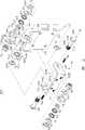
图2是本发明铰链结构较佳实施例的分解图;Fig. 2 is an exploded view of a preferred embodiment of the hinge structure of the present invention;
图3是本发明铰链结构较佳实施例一方向的立体图;Fig. 3 is a perspective view of a preferred embodiment of the hinge structure of the present invention;
图4是本发明铰链结构较佳实施例另一方向的立体图;Fig. 4 is a perspective view in another direction of a preferred embodiment of the hinge structure of the present invention;
图5是沿图3中的V-V向的局部剖视图。Fig. 5 is a partial sectional view along the V-V direction in Fig. 3 .
【具体实施方式】【Detailed ways】
本发明铰链结构以应用于液晶显示器为例说明。The hinge structure of the present invention is illustrated by taking the application to a liquid crystal display as an example.
请参阅图1,该液晶显示器包括一显示屏壳体100和一支座200,该显示屏壳体100与支座200通过一铰链结构300可转动连接。Referring to FIG. 1 , the liquid crystal display includes a
请参阅图2至图4,该铰链结构300包括一支架10、一底座20及二枢接装置(图未标)。每一枢接装置均包括一枢轴30、一摩擦片41、一摩擦片42、一垫圈51、一垫圈52、一弹片61、一弹片62、一扭簧70、一限位垫片80、一螺母90及一螺钉94。Please refer to FIG. 2 to FIG. 4 , the
该支架10包括一安装部12、一连接部14及二延伸部16。该安装部12为板状,其包括一表面120,且安装部12上均匀开设有四个安装孔122,安装孔122为通孔。该连接部14为板状,且厚度大于安装部12的厚度,其一端与安装部12相接,其另一端上间隔设有二近似三角形凸起142。每一凸起142上开设一固定槽144,该固定槽144与安装部12的表面120位于支架10的同一侧。该延伸部16靠设于连接部14的凸起142外侧,其朝支架10外侧延伸,且朝安装部12的表面120一侧倾斜。延伸部16大体为圆柱状,其轴线平行于安装部12。延伸部16上开设有一贯通延伸部16两端的枢轴孔160,延伸部16的一端开设一端孔162,其另一端开设一端孔163,该端孔162、163的直径大于枢轴孔160的直径,且端孔162、163分别包括二相对卡槽(图未标)。该延伸部16的周缘处还开设有一缺口164。The
该底座20包括一基板22和二侧板24。该基板22为长方板,二侧板24分别设于其两端,且侧板24垂直地设于基板22同侧。基板22上开设有四个装配孔222,装配孔222内设有螺纹,该四装配孔222呈“八”字行排布,基板22的上下两侧中央分别开设有一半圆槽224,基板22上设有四凸环226,凸环226与对应装配孔222同心且设于侧板24同侧。每一侧板24上开设一第一变形孔242及一圆孔244,圆孔244内设有螺纹。The
该枢轴30一端具一固定部302,另一端具一枢转部306。该固定部302为盘状,枢转部306大体为柱状,枢转部306相对固定部302一端设有外螺纹308,枢转部306上设有二沿其轴线方向延伸的对称平面304,使枢转部306的截面形状及大小与底座20的第一变形孔242对应。The
该摩擦片41、42大体为圆环状,其外缘处对称设有二凸块412、422。The
该垫圈51、52为中心开孔的圆片,其中心的开孔为第二变形孔512、522,第二变形孔512、522的形状及大小与底座20的第一变形孔242对应。The
该弹片61、62大体为一中心开孔的碟状片,其具有弹性。The
该扭簧70具多个柱状簧圈(图未标),其包括一第一固定端702及一第二固定端704,该第一固定端702沿簧圈径向延伸,第二固定端704沿簧圈轴向延伸。扭簧70的簧圈直径大于垫圈51、52及弹片61、62的外径。The
该限位垫片80大体为环状,其中心具一第三变形孔802,其周缘设有一限位块804。第三变形孔802的形状及大小与底座20的第一变形孔242对应,限位块804大体沿限位垫片80的渐开线方向延伸。限位垫片80的外径大于扭簧70的簧圈直径。The limiting
该螺母90大体为六棱柱,其中心开设有螺孔902。The
该螺钉94从底座20外侧插入底座20的圆孔244内且与圆孔244的螺纹配合,并部分伸入底座20内侧而正对支架10的缺口164以限制底座20相对支架10的转动角度,从而限制液晶显示器的显示屏壳体100相对支座200的俯仰角度。The
装配时,请一并参阅图5,先将摩擦片41、42设置于支架10的端孔162、163处,使摩擦片41、42的凸块412、422位于支架10端孔162、163的卡槽处,因此摩擦片41、42不能相对支架10转动;接着将底座20对应支架10而设,使底座20的第一变形孔242对正支架10的枢轴孔160,且底座20的二侧板24均位于支架10的延伸部16外侧,此时,将枢轴30从支架10外侧插入底座20的第一变形孔242及支架10的枢轴孔160,枢轴30的枢转部306与底座20的第一变形孔242配合,因此枢轴30不能相对底座20转动;然后依次将一垫圈51、一弹片61、一弹片62、一垫圈52、一扭簧70及一限位垫片80套至一枢轴30上,弹片61、62背靠背而设,扭簧70的第一固定端702卡于支架10的固定槽144处,其第二固定端702靠设于限位垫片80的限位块804处;最后将螺母90通过螺纹连接固定于枢轴30上,并将螺钉94插入底座20的圆孔244,由此一枢接装置装配完毕,另一枢接装置以相同方式装配。该扭簧70上设有预紧力,摩擦片42、垫圈51、弹片61、62,垫圈52、限位垫片80及螺母90依次紧密靠设。该铰链结构300装配完毕后,摩擦片41、42相对支架10固定,枢轴30、垫圈51、52,限位垫片80及螺母90相对底座20固定,扭簧70的第一固定端702固定于支架10,其第二固定端704抵靠于底座20。When assembling, please refer to Fig. 5 together, and first set the
当该铰链结构300装设于液晶显示器上时,其支架10通过其安装孔122固定至液晶显示器的支座200上,底座20通过其装配孔222固定至液晶显示器的显示屏壳体100上。When the
工作时,扳动液晶显示器的显示屏壳体100,显示屏壳体100带动底座20一起转动,枢轴30、垫圈51、52,限位垫片80及螺母90由于枢轴30的枢转部306与变形孔242、512、522、802的配合而随底座20一起转动,限位垫片80使扭簧71的第二固定端704随底座20转动而使扭簧70的扭力改变,扭簧70的扭力因底座20转动方向的不同而增大或减小;支架10相对液晶显示器的支座200固定,当显示屏壳体100转动到一定角度时,支架10的缺口164处抵靠螺钉94而不能继续转动。在此过程中,由于弹片61、62的弹力使摩擦片42、垫圈51、弹片61、62,垫圈52、限位垫片80与螺母90紧密抵靠并产生轴向力,而使垫圈51、52与弹片61、62及摩擦片42之间产生较大摩擦力,从而使底座20相对支架10可保持于所调整的位置,即实现液晶显示器的显示屏壳体100自由定位。During work, the
可以理解,枢轴30的枢转部306可为其它形状,只需其为非圆截面即可。枢轴30上可不设外螺纹308,螺母90也可由其它卡固件代替而采用其它卡固形式,如焊接、铆接等。所述枢接装置可仅为一个。本铰链结构300并不限于应用于液晶显示器上,其也可用于液晶电视、笔记本计算机及数码相机等电子装置上。支架10不限于固定于液晶显示器的支座200上,其也可固定于液晶显示器的显示屏壳体100上,对应地,底座20也可固定于液晶显示器的支座200上。螺钉94可为其它阻挡件,只需其能固定于底座20的圆孔244内而能抵靠支架10的缺口164处即可,如销钉等。It can be understood that the pivoting
Claims (13)
Priority Applications (2)
| Application Number | Priority Date | Filing Date | Title |
|---|---|---|---|
| CNB2005101021082ACN100467890C (en) | 2005-12-01 | 2005-12-01 | hinge structure |
| US11/309,439US20070136994A1 (en) | 2005-12-01 | 2006-08-04 | Hinge assembly for flat display monitor |
Applications Claiming Priority (1)
| Application Number | Priority Date | Filing Date | Title |
|---|---|---|---|
| CNB2005101021082ACN100467890C (en) | 2005-12-01 | 2005-12-01 | hinge structure |
Publications (2)
| Publication Number | Publication Date |
|---|---|
| CN1978929A CN1978929A (en) | 2007-06-13 |
| CN100467890Ctrue CN100467890C (en) | 2009-03-11 |
Family
ID=38130197
Family Applications (1)
| Application Number | Title | Priority Date | Filing Date |
|---|---|---|---|
| CNB2005101021082AExpired - Fee RelatedCN100467890C (en) | 2005-12-01 | 2005-12-01 | hinge structure |
Country Status (2)
| Country | Link |
|---|---|
| US (1) | US20070136994A1 (en) |
| CN (1) | CN100467890C (en) |
Families Citing this family (16)
| Publication number | Priority date | Publication date | Assignee | Title |
|---|---|---|---|---|
| CN2736889Y (en)* | 2004-07-17 | 2005-10-26 | 鸿富锦精密工业(深圳)有限公司 | Portable optical disk player |
| CN101201077A (en)* | 2006-12-15 | 2008-06-18 | 鸿富锦精密工业(深圳)有限公司 | hinge structure |
| WO2016053249A1 (en)* | 2014-09-29 | 2016-04-07 | Hewlett-Packard Development Company, L.P. | Hinge assembly with compressible sleeve |
| US9605460B2 (en)* | 2015-01-27 | 2017-03-28 | Freund—Vector Corporation | Hinge dampening device for granulation bowl lid |
| CN104895911A (en)* | 2015-05-13 | 2015-09-09 | 赵士立 | Baffle plate mounting rotation adjusting mechanism |
| CN104832532B (en)* | 2015-05-18 | 2017-08-11 | 李林波 | Rotating shaft capable of adjusting torque force |
| CN105276435A (en)* | 2015-11-05 | 2016-01-27 | 湖州科中电光源有限公司 | LED lamp |
| CN106499933B (en)* | 2016-10-24 | 2018-05-29 | 田雨川 | More anti-loosening rack joint devices of friction plate |
| CN107676602B (en)* | 2017-09-18 | 2020-01-10 | 广州视源电子科技股份有限公司 | Supporting frame |
| CN110271375A (en)* | 2018-03-14 | 2019-09-24 | 北京京东尚科信息技术有限公司 | Hoofing part mechanism and conveying equipment with the mechanism |
| CN110499979B (en)* | 2018-05-16 | 2021-08-20 | 无锡小天鹅电器有限公司 | Door shaft assembly and washing machine |
| CN110630925A (en)* | 2019-09-03 | 2019-12-31 | 苏寅达 | A piano desk lamp that can be dimmed by a gesture switch |
| CN111204151A (en)* | 2019-12-05 | 2020-05-29 | 国网山西省电力公司晋城供电公司 | A portable inspection record board structure for power company information statistics |
| CN110985831B (en)* | 2019-12-23 | 2024-04-19 | 浙江中科冠腾科技股份有限公司 | Internal sinking type double-rotation mechanism and screen comprising same |
| CN112372665A (en)* | 2021-01-21 | 2021-02-19 | 苏州好博医疗器械有限公司 | Joint assembly |
| CN119858674B (en)* | 2025-03-21 | 2025-06-06 | 北京钧天航宇技术有限公司 | Miniature expansion hinge mechanism and spacecraft |
Citations (7)
| Publication number | Priority date | Publication date | Assignee | Title |
|---|---|---|---|---|
| CN2379638Y (en)* | 1999-03-04 | 2000-05-24 | 林文祺 | Positioning hinge |
| JP2000356215A (en)* | 1999-06-15 | 2000-12-26 | Nhk Spring Co Ltd | Shaft locking device |
| US20020083554A1 (en)* | 2001-01-03 | 2002-07-04 | Lu Sheng-Nan | Concealed retaining device for a pivot |
| US6539582B1 (en)* | 2000-02-22 | 2003-04-01 | P.K. Tech System Co., Ltd. | Hinge device |
| CN2668785Y (en)* | 2003-11-20 | 2005-01-05 | 黄国城 | Improved Display Hinge Axis |
| CN2669550Y (en)* | 2003-12-01 | 2005-01-05 | 兆利资讯工业股份有限公司 | panel hinge |
| JP2005315355A (en)* | 2004-04-28 | 2005-11-10 | Tachibana Mamoru | Hinge |
Family Cites Families (22)
| Publication number | Priority date | Publication date | Assignee | Title |
|---|---|---|---|---|
| US5269047A (en)* | 1992-06-10 | 1993-12-14 | Lu Sheng N | Hinge device for casings |
| US5335142A (en)* | 1992-12-21 | 1994-08-02 | Ast Research, Inc. | Portable computer display tilt/swivel mechanism |
| US6018847A (en)* | 1998-07-02 | 2000-02-01 | Lu; Sheng-Nan | Hinge axle device for a LCD monitor |
| US6378830B1 (en)* | 2000-10-05 | 2002-04-30 | Lu Sheng-Nan | Adjustable support for an LCD monitor |
| US6481057B2 (en)* | 2001-03-20 | 2002-11-19 | Wen-Chi Lin | Positioning hinge adapted between a computer main body and a display |
| US6671928B2 (en)* | 2001-05-23 | 2004-01-06 | Kuo-Cheng Huang | Hinge assembly for monitor |
| AU2002354335A1 (en)* | 2001-12-24 | 2003-07-15 | Lg Electronics Inc. | Hinge assembly for flat panel display appliance |
| CN1279419C (en)* | 2001-12-24 | 2006-10-11 | Lg电子株式会社 | Hinge assembly for flat panel display appliance |
| MXPA04003745A (en)* | 2001-12-24 | 2004-07-23 | Lg Electronics Inc | Hinge assembly for flat panel display appliance. |
| KR100443613B1 (en)* | 2001-12-27 | 2004-08-09 | 엘지전자 주식회사 | Hinge structure for plane-type display device |
| TW531019U (en)* | 2001-12-31 | 2003-05-01 | Hinge Basestrong Co Ltd | Improved LCD seat |
| TW566580U (en)* | 2002-01-30 | 2003-12-11 | Chung-Nan Hsieh | Pivotal hinge and slit-type conical elastic pad |
| KR20020035046A (en)* | 2002-03-14 | 2002-05-09 | 이육권 | Device of hinge for electrical maachchinery |
| TW545614U (en)* | 2002-04-18 | 2003-08-01 | Quanta Comp Inc | Flat panel display and its foldable base |
| US6665907B1 (en)* | 2002-05-30 | 2003-12-23 | Lu Sheng-Nan | Washer for a pivot hinge |
| US20030182761A1 (en)* | 2002-07-02 | 2003-10-02 | Kidd Gaylon M. | Hinge pin and replacement method for vehicle door hinge |
| EP1388629A1 (en)* | 2002-08-05 | 2004-02-11 | Elitegroup Computer Systems Co.,Ltd. | Automatic homing rotary hinge |
| US6796541B2 (en)* | 2002-08-29 | 2004-09-28 | Shin Zu Shing Co., Ltd. | Support for an LCD monitor |
| US6581893B1 (en)* | 2002-09-05 | 2003-06-24 | Shin Zu Shing Co., Ltd. | Stand for an LCD monitor |
| US20040055114A1 (en)* | 2002-09-19 | 2004-03-25 | Lu Sheng-Nan | Hinge assembly for supporting LCD display panel |
| US6954221B2 (en)* | 2002-09-20 | 2005-10-11 | Alpha Wu | Safety structure of a desk top LCD |
| US6666422B1 (en)* | 2002-12-02 | 2003-12-23 | Shin Zu Shing Co., Ltd. | Foldable hinge bracket for a laptop computer |
- 2005
- 2005-12-01CNCNB2005101021082Apatent/CN100467890C/ennot_activeExpired - Fee Related
- 2006
- 2006-08-04USUS11/309,439patent/US20070136994A1/ennot_activeAbandoned
Patent Citations (7)
| Publication number | Priority date | Publication date | Assignee | Title |
|---|---|---|---|---|
| CN2379638Y (en)* | 1999-03-04 | 2000-05-24 | 林文祺 | Positioning hinge |
| JP2000356215A (en)* | 1999-06-15 | 2000-12-26 | Nhk Spring Co Ltd | Shaft locking device |
| US6539582B1 (en)* | 2000-02-22 | 2003-04-01 | P.K. Tech System Co., Ltd. | Hinge device |
| US20020083554A1 (en)* | 2001-01-03 | 2002-07-04 | Lu Sheng-Nan | Concealed retaining device for a pivot |
| CN2668785Y (en)* | 2003-11-20 | 2005-01-05 | 黄国城 | Improved Display Hinge Axis |
| CN2669550Y (en)* | 2003-12-01 | 2005-01-05 | 兆利资讯工业股份有限公司 | panel hinge |
| JP2005315355A (en)* | 2004-04-28 | 2005-11-10 | Tachibana Mamoru | Hinge |
Also Published As
| Publication number | Publication date |
|---|---|
| US20070136994A1 (en) | 2007-06-21 |
| CN1978929A (en) | 2007-06-13 |
Similar Documents
| Publication | Publication Date | Title |
|---|---|---|
| CN100489324C (en) | Hinge device | |
| CN100467891C (en) | hinge device | |
| CN100467890C (en) | hinge structure | |
| CN100489325C (en) | Hinge mechanism | |
| CN101207994A (en) | hinge structure | |
| CN101672416B (en) | Supporting device | |
| US8215596B2 (en) | Hinge assembly | |
| US8205305B2 (en) | Hinge mechanism | |
| US7753331B2 (en) | Flat display device with foldable supporting base | |
| US8199473B2 (en) | Support stand for flat-panel display monitor | |
| CN101201077A (en) | hinge structure | |
| US11725769B2 (en) | Supporting device | |
| US7987560B2 (en) | Hinge assembly | |
| CN101713487A (en) | Lifting mechanism | |
| CN101737417A (en) | Hinge structure | |
| CN100445584C (en) | hinge device | |
| CN101201078A (en) | hinge structure | |
| US20050125951A1 (en) | Hinge structure | |
| TWI308997B (en) | Hinge mechanism | |
| CN100467889C (en) | hinge device | |
| US20090070962A1 (en) | Open-slot hinge fixing assembly | |
| TWI323636B (en) | Hinge device | |
| TWI388211B (en) | Support device | |
| TWI324039B (en) | Hinge structure | |
| TWM557495U (en) | Two-stage torque force pivot device |
Legal Events
| Date | Code | Title | Description |
|---|---|---|---|
| C06 | Publication | ||
| PB01 | Publication | ||
| C10 | Entry into substantive examination | ||
| SE01 | Entry into force of request for substantive examination | ||
| C14 | Grant of patent or utility model | ||
| GR01 | Patent grant | ||
| C17 | Cessation of patent right | ||
| CF01 | Termination of patent right due to non-payment of annual fee | Granted publication date:20090311 Termination date:20131201 |