CN100466979C - Tomography apparatus with recording system according to system angle and method for determining system angle - Google Patents
Tomography apparatus with recording system according to system angle and method for determining system angleDownload PDFInfo
- Publication number
- CN100466979C CN100466979CCNB2005100813351ACN200510081335ACN100466979CCN 100466979 CCN100466979 CCN 100466979CCN B2005100813351 ACNB2005100813351 ACN B2005100813351ACN 200510081335 ACN200510081335 ACN 200510081335ACN 100466979 CCN100466979 CCN 100466979C
- Authority
- CN
- China
- Prior art keywords
- detector
- measured value
- system angle
- imaging
- output signal
- Prior art date
- Legal status (The legal status is an assumption and is not a legal conclusion. Google has not performed a legal analysis and makes no representation as to the accuracy of the status listed.)
- Expired - Fee Related
Links
Images


Classifications
- A—HUMAN NECESSITIES
- A61—MEDICAL OR VETERINARY SCIENCE; HYGIENE
- A61B—DIAGNOSIS; SURGERY; IDENTIFICATION
- A61B6/00—Apparatus or devices for radiation diagnosis; Apparatus or devices for radiation diagnosis combined with radiation therapy equipment
- A61B6/02—Arrangements for diagnosis sequentially in different planes; Stereoscopic radiation diagnosis
- A61B6/03—Computed tomography [CT]
- A61B6/032—Transmission computed tomography [CT]
- A—HUMAN NECESSITIES
- A61—MEDICAL OR VETERINARY SCIENCE; HYGIENE
- A61B—DIAGNOSIS; SURGERY; IDENTIFICATION
- A61B6/00—Apparatus or devices for radiation diagnosis; Apparatus or devices for radiation diagnosis combined with radiation therapy equipment
- A61B6/40—Arrangements for generating radiation specially adapted for radiation diagnosis
- A61B6/4007—Arrangements for generating radiation specially adapted for radiation diagnosis characterised by using a plurality of source units
- A61B6/4014—Arrangements for generating radiation specially adapted for radiation diagnosis characterised by using a plurality of source units arranged in multiple source-detector units
Landscapes
- Health & Medical Sciences (AREA)
- Life Sciences & Earth Sciences (AREA)
- Engineering & Computer Science (AREA)
- Medical Informatics (AREA)
- Optics & Photonics (AREA)
- Biomedical Technology (AREA)
- Biophysics (AREA)
- High Energy & Nuclear Physics (AREA)
- Veterinary Medicine (AREA)
- Nuclear Medicine, Radiotherapy & Molecular Imaging (AREA)
- Public Health (AREA)
- Pathology (AREA)
- Radiology & Medical Imaging (AREA)
- Physics & Mathematics (AREA)
- Heart & Thoracic Surgery (AREA)
- Molecular Biology (AREA)
- Surgery (AREA)
- Animal Behavior & Ethology (AREA)
- General Health & Medical Sciences (AREA)
- Pulmonology (AREA)
- Theoretical Computer Science (AREA)
- Apparatus For Radiation Diagnosis (AREA)
- Nuclear Medicine (AREA)
Abstract
Translated fromChinese
Description
Translated fromChinese技术领域technical field
本发明涉及一种具有至少两个按照系统角设置的拍摄系统的成像断层造影设备,其至少具有The invention relates to an imaging tomography system with at least two recording systems arranged according to system angles, which has at least
-第一拍摄系统,具有第一辐射器和用于产生探测器输出信号的第一探测器,该探测器输出信号是由第一辐射器发出并穿过测量区域的射线的吸收程度的度量,- a first imaging system with a first radiator and a first detector for generating a detector output signal which is a measure of the degree of absorption of the radiation emitted by the first radiator and passing through the measurement region,
-第二拍摄系统,具有第二辐射器和用于产生探测器输出信号的第二探测器,该探测器输出信号是由第二辐射器发出并穿过测量区域的射线的吸收程度的度量,- a second imaging system with a second radiator and a second detector for generating a detector output signal which is a measure of the degree of absorption of the radiation emitted by the second radiator and passing through the measurement region,
其中在方位角方向上第一拍摄系统以第一系统角、第二拍摄系统以第二系统角围绕共同的旋转轴可旋转地设置。本发明还涉及一种为这种断层造影设备确定两个拍摄系统的相应系统角的方法。In the azimuth direction, the first imaging system is arranged rotatably at a first system angle and the second imaging system at a second system angle about a common axis of rotation. The invention also relates to a method for determining the respective system angles of two recording systems for such a tomography system.
背景技术Background technique
由DE19615456A1公开了一种只具有一个拍摄系统的断层造影设备,该设备为了校正再现图像中的图像失真而在该拍摄系统的测量平面和患者卧榻平面之间确定角度误差。DE 196 15 456 A1 discloses a tomography system with only one recording system, which determines an angular error between the measurement plane of the recording system and the plane of the patient table in order to correct image distortions in the reconstructed image.
在US4991190、DE2951222A1、DE2916848A1和US6421412B1中公开了其它具有至少两个拍摄系统的断层造影设备。这种具有多个拍摄系统的断层造影设备与只具有一个拍摄系统的设备相比其优点在于,以更快的扫描速度或以更高的扫描分辨率来检查对象。如果必须最小化再现图像中由于自愿或不自愿的对象运动(例如生物的待检查器官)而产生的运动伪影,则快的扫描速度具有很重要的意义。在例如心脏的检查中,为了再现无伪影的断层或立体图像,需要在不同旋转角度位置上的所有用于再现的照片都尽可能采集心脏的相同运动状态。Further tomography devices having at least two recording systems are known from US Pat. Such a tomography system with multiple recording systems has the advantage, compared to systems with only one recording system, that the object is examined at a faster scanning speed or at a higher scanning resolution. A fast scan speed is of great importance if motion artifacts in the reconstructed image due to voluntary or involuntary object motions (eg organs of the organism to be examined) have to be minimized. In the examination of the heart, for example, in order to reproduce an artifact-free tomographic or stereoscopic image, it is necessary that all images used for reconstruction at different rotational angle positions capture as much as possible the same motion state of the heart.
除了单个图像照片之外,对于医疗检查来说还产生断层或立体图像序列来显示运动过程。在此,更快的扫描速度提供了改善所显示的运动过程的时间分辨率的优点,从而也可以采集快速变化的运动状态。In addition to individual image photographs, tomographic or stereoscopic image sequences are also generated for medical examinations to show movement processes. Here, the faster scanning speed offers the advantage of an improved temporal resolution of the displayed motion sequence, so that rapidly changing motion states can also be detected.
但是,具有多个拍摄系统的断层造影设备可以这样运行,即与只具有一个拍摄系统的断层造影设备相比达到更高的扫描分辨率。如果生物的器官或器官部分必须在小检查区域内被分析,如在检查血管的情况下,则具有特别重要的意义。However, a tomography system with a plurality of recording systems can be operated in such a way that a higher scanning resolution can be achieved compared to a tomography system with only one recording system. This is of particular importance if organs or organ parts of living organisms have to be analyzed in small examination areas, as in the case of examination of blood vessels.
在具有多个拍摄系统的断层造影设备中,既以提高扫描速度的运行方式又以提高扫描分辨率的运行方式将不同拍摄系统的表示出的探测器输出信号相互结算,以再现出断层或立体图像。在此,数据的结算在已知系统角的条件下进行,拍摄系统以该系统角在方位角方向上围绕共同的旋转轴设置。In a tomography system with a plurality of recording systems, the indicated detector output signals of the different recording systems are combined with each other, both in an operating mode with increased scanning speed and in an operating mode with increased scanning resolution, in order to reconstruct slices or volumes. image. The calculation of the data takes place here with the known system angle with which the recording system is arranged in the azimuth direction around a common axis of rotation.
发明内容Contents of the invention
本发明要解决的技术问题在于,构造开头所述类型的成像断层造影设备和提供开头所述类型的方法,可以按照简单方式确定在方位角方向上以不同的旋转角速度围绕共同的旋转轴设置的拍摄系统的系统角。The technical problem to be solved by the present invention is to construct an imaging tomography system of the type mentioned at the outset and to provide a method of the type mentioned at the beginning, which can be easily determined in the azimuth direction at different rotational angular velocities about a common axis of rotation. The system angle of the camera system.
根据本发明设置了用于确定两个系统角的装置,其具有可定位在测量区域内但系统轴之外的一个参考位置上的参考对象,和计算装置,该计算装置针对两个拍摄系统在不同旋转角位置上的至少一个基本上恒定的旋转角速度,从第一探测器的探测器输出信号中分别计算一个对应于该第一探测器的测量值,和从第二探测器的探测器输出信号中分别计算一个对应于该第二探测器的测量值,所述测量值针对参考对象在相应探测器中成像的参考位置,以及该计算装置从这样获得的不同旋转角位置上的测量值中确定两个拍摄系统的系统角。对应于各探测器的测量值通常代表参考对象在该探测器中的成像位置。According to the invention, a device for determining the angles of the two systems is provided, which has a reference object which can be positioned at a reference position in the measuring region but outside the system axis, and a calculation device which is used for the two recording systems at a reference position. at least one substantially constant rotational angular velocity at different rotational angular positions, a measurement value corresponding to the first detector is calculated from the detector output signal of the first detector, and a detector output from the second detector Signals are respectively calculated a measurement value corresponding to the second detector for the reference position at which the reference object is imaged in the corresponding detector, and the calculation means from the measurement values thus obtained at different rotational angle positions Determine the system angles of the two camera systems. The measurement values corresponding to each detector typically represent the imaged position of the reference object in that detector.
本发明基于以下基本认知,即在方位角方向上围绕共同旋转轴设置的两个拍摄系统的系统角由于制造过程中的建造容差以及由于拍摄系统高速旋转时的强加速力而可能发生移动。理想情况下设置的系统角的额定值和拍摄系统的实际系统角之差取决于旋转速度的大小。但是,在再现断层图像或立体图像中考虑的额定值和实际存在的系统角之间的偏差产生了再现图像中的伪影,并因此一般导致可能达到的图像质量的恶化。The invention is based on the fundamental recognition that the system angles of two recording systems arranged around a common axis of rotation in the azimuth direction can shift due to construction tolerances during the manufacturing process and due to strong acceleration forces when the recording systems rotate at high speeds . The difference between the setpoint value of the ideally set system angle and the actual system angle of the recording system depends on the magnitude of the rotation speed. However, deviations between the target values considered in the reconstruction of the tomographic or stereoscopic image and the actually existing system angles produce artifacts in the reconstructed image and thus generally lead to a deterioration of the achievable image quality.
基于所建议的系统角的确定,可以改善由探测器输出信号产生的断层图像或立体图像,其中可考虑将精确确定的系统角用于再现。通过这种方式,可以避免在再现时由于错误的作为基础的拍摄系统的系统角而在断层或立体图像中出现的伪影。On the basis of the proposed determination of the system angle, the tomographic or stereo image produced from the detector output signal can be improved, wherein the precisely determined system angle can be taken into account for the reconstruction. In this way, artifacts that occur in tomographic or stereoscopic images due to incorrect system angles of the underlying recording system during reconstruction can be avoided.
确定系统角可以这样价廉和特别简单地实施,即对设置在测量平面中的参考对象的探测器输出信号只需进行一次分析。可以以较少的花费针对不同的旋转角速度并由此针对断层造影设备的任意运行方式确定拍摄系统的系统角。The determination of the system angle can be carried out inexpensively and particularly simply in that only one evaluation of the detector output signal of the reference object arranged in the measurement plane is required. The system angle of the recording system can be determined with little effort for different rotational angular velocities and thus for any mode of operation of the tomography system.
借助成本函数可以特别有效和计算上容易换算地确定系统角,该成本函数将加权后的和项相加,其中每一个和项都可以由对应于探测器的测量值和一个成像函数之差构成,其中该成像函数描述参考对象在该探测器中成像的参考位置的理论测量值与该参考位置、两个拍摄系统的几何特性、旋转角位置和待优化的系统角之间的依赖关系。成像函数优选按照平面几何坐标的形式给定。The system angle can be determined particularly efficiently and computationally easily scaled by means of a cost function which adds weighted sum terms, where each sum term can be formed from the difference between the measured values corresponding to the detector and an imaging function , wherein the imaging function describes the dependence of the theoretical measured value of the reference position of the reference object imaged in the detector on the reference position, the geometric properties of the two imaging systems, the rotational angular position and the system angle to be optimized. The imaging function is preferably specified in the form of plane geometric coordinates.
根据两个系统角之差可以确定系统角距离,其有利地只包含关于两个拍摄系统的相对设置的信息,并可以通过该方式有利地直接用于再现图像。A system angular distance can be determined from the difference between the two system angles, which advantageously contains only information about the relative arrangement of the two recording systems and can thus advantageously be used directly for reconstructing the image.
为了使对参考对象在两个拍摄系统的探测器上的成像不取决于拍摄系统的旋转角位置,并且为了对探测器输出信号的分析简单,参考对象具有旋转对称的结构。In order that the imaging of the reference object on the detectors of the two imaging systems does not depend on the rotational angular position of the imaging systems, and to simplify the analysis of the output signals of the detectors, the reference object has a rotationally symmetrical structure.
如果参考对象可以在多个探测器元件上成像,则基于探测器输出信号计算对应于探测器的测量值和计算参考对象在该探测器上成像的位置可以对探测器输出信号的噪声具有特别强的抵抗能力。优选根据探测器输出信号在强度重心的意义下确定该位置。If a reference object can be imaged on more than one detector element, the calculation of the measurement corresponding to the detector based on the detector output signal and the calculation of the position of the reference object imaged on that detector can have a particularly strong effect on the noise of the detector output signal. resistance. The position is preferably determined from the detector output signal in terms of the center of gravity of the intensity.
优选地,在对患者进行实际测量之前在校准过程中确定系统角。Preferably, the system angles are determined during the calibration process before actual measurements are taken on the patient.
为了在检查患者的正常运行中也能直接访问所确定的断层造影设备的拍摄系统的系统角,在本发明的优选实施方式中设置存储器,其中存储针对多个不同的基本上恒定的旋转角速度而确定的系统角。In order to be able to directly access the determined system angle of the imaging system of the tomography system even during normal operation of the patient examination, in a preferred embodiment of the invention a memory is provided in which the values for a plurality of different substantially constant rotational angular velocities are stored. Determine the system angle.
附图说明Description of drawings
本发明的实施例以及本发明的其它优选实施方式示意性地显示在附图中。其中示出:An exemplary embodiment of the invention as well as other preferred embodiments of the invention are shown schematically in the drawings. which shows:
图1以透视总图示出根据本发明的断层造影设备,FIG. 1 shows a perspective general view of a tomography device according to the invention,
图2以横截面的形式示出图1的断层造影设备的两个拍摄系统,其中具有定位在这些拍摄系统测量区域中的参考对象,FIG. 2 shows two recording systems of the tomography system of FIG. 1 in cross-section with a reference object positioned in the measurement range of these recording systems,
图3示出图2的具有移动了的系统角的两个拍摄系统,FIG. 3 shows the two recording systems of FIG. 2 with shifted system angles,
图4示出参考对象对不同的旋转角位置的在探测器上的成像,Figure 4 shows the imaging of the reference object on the detector for different rotational angle positions,
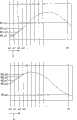
图5示出各探测器的参考对象的测量值与两个拍摄系统的旋转角位置的依赖关系。FIG. 5 shows the dependence of the measured values of the reference object of the individual detectors on the rotational angular position of the two recording systems.
具体实施方式Detailed ways
图1示出根据本发明的断层造影设备3,在此为X射线计算机断层造影设备的形式,其具有患者卧榻6用于容纳和定位患者8。患者卧榻6包括可以运动的桌板7,借助该桌板患者8可以穿过断层造影设备3的外壳10中的开口9而进入检查或扫描区域。此外,在螺旋扫描期间桌板7还进行连续的轴向平移。FIG. 1 shows a
在断层造影设备3内具有图1中未示出的支架(测量车),其可以高速围绕穿过患者8的旋转轴5旋转。Inside the
为了达到高的扫描速度或高的扫描分辨率,在支架上按照预定方式设置两个拍摄系统1.1,1.2、2.1,2.2。第一拍摄系统1.1,1.2在该实施例中具有X射线管作为第一辐射器1.1以及例如8行的X射线探测器阵列作为第一探测器1.2。第二拍摄系统2.1,2.2在该实施例中包括另一个X射线管作为第二辐射器2.1以及另一个例如8行的X射线探测器阵列作为第二探测器2.2。两个拍摄系统在方位角方向上分别以确定的系统角围绕旋转轴5固定设置。In order to achieve high scanning speed or high scanning resolution, two imaging systems 1.1, 1.2, 2.1, 2.2 are arranged on the support in a predetermined manner. In the exemplary embodiment, first recording system 1.1, 1.2 has an x-ray tube as first radiator 1.1 and an array of x-ray detectors of, for example, 8 rows as first detector 1.2. In this exemplary embodiment, the second recording system 2.1, 2.2 comprises a further x-ray tube as the second radiator 2.1 and a further, for example 8-row, x-ray detector array as the second detector 2.2. The two recording systems are fixedly arranged in the azimuth direction around the axis of
X射线探测器阵列例如基于可电读取的闪烁器陶瓷即所谓的UFC陶瓷制造,并用于产生探测器输出信号,探测器输出信号是对从对应的辐射器1.1和2.1发出并穿过测量区域的射线的吸收程度的度量。还可以采用其它探测器,例如具有256或更多行的平面探测器来产生探测器输出信号。The X-ray detector array is produced, for example, based on electrically readable scintillator ceramics, so-called UFC ceramics, and is used to generate detector output signals which are emitted from corresponding radiators 1.1 and 2.1 and pass through the measurement area A measure of the degree of absorption of a ray. Other detectors, such as planar detectors with 256 or more rows, may also be used to generate the detector output signal.
在控制和图像计算机4中采用图像再现算法将两个在相对不同旋转角位置上的、优选在同一平面内扫描的拍摄系统1.1,1.2、2.1,2.2的探测器输出信号处理成断层图像或立体图像。其中,两个拍摄系统的探测器输出信号首先组合成一个共同的投影或原始数据组(“混合”)。由医生等等对断层造影设备3的操作同样通过控制和图像计算机4进行。In the control and image computer 4 the output signals of the detectors of the two recording systems 1.1, 1.2, 2.1, 2.2 at relatively different rotational angle positions, preferably scanned in the same plane, are processed into a tomographic image or a volume using an image reconstruction algorithm. image. In this case, the detector output signals of the two recording systems are first combined to form a common projection or raw data set (“mixing”). The operation of the
图2和3以横截面的形式示出图1的两个拍摄系统1.1,1.2、2.1,2.2。2 and 3 show the two recording systems 1.1, 1.2, 2.1, 2.2 of FIG. 1 in cross section.
为了说明对应于各拍摄系统的系统角、旋转角位置和可以在两个拍摄系统1.1,1.2、2.1,2.2的共同测量区域内定位的参考对象的位置,绘出笛卡尔坐标系统,具有第一轴x、第二轴y和设置在旋转轴5上的原点。所有角度和位置说明在下述实施例中都涉及这样定义的参考系统。In order to illustrate the system angle, the rotational angle position and the position of the reference object that can be positioned in the common measurement area of the two imaging systems 1.1, 1.2, 2.1, 2.2 for the respective imaging systems, a Cartesian coordinate system is drawn with the first The axis x, the second axis y and the origin are arranged on the axis of
两个拍摄系统1.1,1.2、2.1,2.2可以在方位角方向上围绕共同的旋转轴5按照所绘出的旋转角方向α旋转地设置。第一拍摄系统1.1,1.2以第一系统角γ1、第二拍摄系统2.1,2.2以第二系统角γ2围绕共同的旋转轴5设置。辐射器1.1,2.1和探测器1.2,2.2与旋转轴5之间的距离在本实施例中通过焦点轨道半径Fr来确定。这样在用断层造影设备3检查期间,通过旋转支架,利用两个拍摄系统1.1,1.2、2.1,2.2可从不同投影方向获得在不同的例如绘出的旋转角位置α0,...,αn上的原始图像数据,用这些原始图像数据可以再现出一幅断层或立体图像。The two recording systems 1.1, 1.2, 2.1, 2.2 can be arranged rotatably in the azimuthal direction about a common axis of
在共同的测量区域14中,如图2所示,参考对象R设置在位置Rx、Ry上,该参考对象根据旋转角位置α0,...,αn既在第一探测器1.2又在第二探测器2.2中产生相应的投影图像。参考对象R的位置Rx、Ry原理上是可以任意预定的,但必须位于两个拍摄系统1.1,1.2、2.1,2.2的共同旋转轴5之外以及该共同测量区域内。在横截面中,分别示出用于产生探测器输出信号的分别具有多个探测器元件的探测器1.2、2.2的一行。从通过投影图像产生的第一探测器1.2的探测器输出信号中,可以计算第一测量值M1,α0,从第二探测器2.2的探测器输出信号中可以计算对应的第二测量值M2,α0。在此,每个测量值分别代表参考对象R在相应探测器1.2或2.2中的位置。In the
从相应探测器1.2或2.2在不同旋转角位置上的探测器输出信号中,通过该方式前后连续地计算对应于该探测器的测量值M1,α0,...,M1,αn或M2,α0,...,M2,αn。探测器输出信号的拍摄在此是在支架的任意但至少基本上恒定的旋转速度下进行的。From the detector output signals of the respective detector 1.2 or 2.2 at different rotational angle positions, the measured values M1, α0, . , . . . , M2, αn. The recording of the detector output signal takes place here at any but at least substantially constant rotational speed of the support.
拍摄系统1.1,1.2、2.1,2.2在方位角方向上围绕共同旋转轴5设置的系统角γ1、γ2,对再现断层或立体图像来说必须是已知的,因此必须具有预定的值。由于在制造过程中的建造容差或由于支架旋转期间的强加速力,拍摄系统1.1,1.2、2.1,2.2可能从其最初的预定位置移动出去。图3以相同的横截面示出图2的两个拍摄系统1.1,1.2、2.1,2.2,其区别在于,图1中最初设置的系统角例如由于建造容差而发生移动。由于该原因,与图2所示的两个拍摄系统1.1,1.2、2.1,2.2的设置相比,在同一旋转角位置α0,...,αn上在两个探测器1.2,2.2中产生了不同的投影图像。再现断层或立体图像时,通过这种方式在不考虑确切系统角γ1、γ2的情况下会在该再现图像中产生伪影。The system angles γ1 , γ2 of the acquisition systems 1.1 , 1.2 , 2.1 , 2.2 arranged in the azimuthal direction about the common axis of
图4示出参考对象R在探测器上(在此是第一探测器1.2)、例如针对不同的旋转角位置α0,...,αn的成像。对应于第一探测器1.2的探测器阵列包括M行。在每一行上分别排列了N个探测器元件。探测器元件A1.1,...AM.N因此设置为矩阵形式。如果参考对象R优选可以在多行探测器元件A1.1到AM.N上成像,则可以实现对测量值M1,α0,...,M1,αn的抗探测器噪声的鲁棒的计算。FIG. 4 shows the imaging of a reference object R on a detector (here the first detector 1 . 2 ), for example for different rotational angular positions α0, . . . , αn. The detector array corresponding to the first detector 1.2 comprises M rows. N detector elements are respectively arranged in each row. The detector elements A1.1, . . . AM.N are thus arranged in matrix form. A robust calculation of the measured values M1, α0, .
基于探测器输出信号特别简单和节省计算时间地确定测量值M1,α0,...,M1,αn是通过计算强度重心来达到的。为此,在最简单的情况下,根据探测器元件位置的行坐标和列坐标分开对该探测器元件A1.1,...AM.N的探测器输出信号(强度值)进行加权、相加并除以相加值的个数(M×N)。为了确定强度重心的列坐标,例如分别将在一个探测器元件中观察的强度值乘以该探测器元件的列坐标。将这样加权的强度值相加,并除以和数。由此得出的值代表强度重心的列坐标。对应的可以确定强度重心的行坐标。A particularly simple and computationally time-saving determination of the measured values M1, α0, . To this end, in the simplest case, the detector output signals (intensity values) of the detector elements A1. Add and divide by the number of added values (M×N). To determine the column coordinates of the intensity centroids, for example, the intensity values observed in a detector element are multiplied by the column coordinates of this detector element. The intensity values thus weighted are summed and divided by the sum. The resulting values represent the column coordinates of the centroids of the intensity. The corresponding row coordinates of the center of gravity of the intensity can be determined.
可以计算的测量值M1,α0,...,M1,αn对应于在探测器1.2中成像的参考对象R的位置,具有子像素单位的精度。The measured values M1, α0, . . . , M1, αn that can be calculated correspond to the position of the reference object R imaged in the detector 1 .
在另一优选实施方式中,参考对象R具有旋转对称的结构,从而如图4所示,对于所有旋转角位置α0,...,αn分别通过参考对象R在探测器1.2上的成像来产生相同的成像轮廓(Abbildungsprofile)Rp0,Rp1,...Rpn。In a further preferred embodiment, the reference object R has a rotationally symmetrical structure, so that, as shown in FIG. 4 , for all rotational angular positions α0, . The same imaging profile (Abbildungsprofile) Rp0, Rp1, . . . Rpn.
满足上述要求的参考对象R例如以圆形或条形结构的对象给出。Reference objects R that meet the above requirements are given, for example, as circular or bar-shaped objects.
两个拍摄系统在不同旋转角位置α0,...,αn上以恒定角速度旋转期间可计算的、对应于相应探测器1.2的测量值M1,α0,...,M1,αn和对应于相应探测器2.2的测量值M2,α0,...,M2,αn用于确定未知的系统角γ1、γ2。图5分别以正弦图的形式示出支架的旋转角位置和所计算的探测器1.2或探测器2.2的测量值之间的关系。The measured values M1, α0, . The measured values M2, α0, . . . , M2, αn of the detector 2.2 are used to determine the unknown system angles γ1, γ2. FIG. 5 shows the relationship between the angular rotational position of the support and the calculated measured values of the probe 1.2 or probe 2.2 in each case in the form of a sinogram.
特别有效和数值上容易实现的系统角γ1、γ2的确定可以分别借助成本函数来实现,该成本函数将加权后的和项相加,其中每一和项都可以由对应于探测器1.2的测量值M1,αi或对应于探测器2.2的测量值M2,αi和一个成像函数S1或成像函数S2之差构成。A particularly efficient and numerically easy determination of the system angles γ1, γ2, respectively, can be achieved by means of a cost function which adds weighted sum terms, each of which can be determined by the measurement corresponding to the detector 1.2 The value M1, αi or the measured value M2, αi corresponding to the detector 2.2 is formed as the difference between an imaging function S1 or an imaging function S2.
在此成像函数S1或成像函数S2描述在该探测器1.2或探测器2.2中成像的参考对象R的理论测量值与该参考对象R的参考位置Rx、Ry、焦点轨道半径Fr、旋转角位置αi和待优化的系统角γ1或γ2之间的依赖关系。Here the imaging function S1 or imaging function S2 describes the theoretical measurement value of the reference object R imaged in the detector 1.2 or detector 2.2 and the reference position Rx, Ry, focus orbital radius Fr, rotation angle position αi of the reference object R and the dependence between the system angle γ1 or γ2 to be optimized.
成像函数S1或成像函数S2通常可以平面几何坐标的形式给定,并具有如下结构:The imaging function S1 or S2 can usually be given in the form of plane geometric coordinates, and has the following structure:
基于成像函数S1或成像函数S2可以这样构成并最小化或优化成本函数Fa,使得可以确定参考对象R的未知位置Rx、Ry和系统角γ1、γ2。根据成本函数的形式相互分开地或统一地实现系统角γ1、γ2的确定。用于确定参考对象R的位置Rx、Ry和系统角γ1、γ2的成本函数是可以这样来给定的,即和项由所述成像函数S1或成像函数S2和在不同旋转角位置上计算的测量值M1,α0,...,M1,αn或M2,α0,...,M2,αn之差来构成:Based on imaging function S1 or imaging function S2 , cost function Fa can be formed and minimized or optimized such that unknown positions Rx, Ry and system angles γ1 , γ2 of reference object R can be determined. Depending on the form of the cost function, the system angles γ1 , γ2 are determined separately or collectively. The cost function for determining the position Rx, Ry and the system angles γ1, γ2 of the reference object R can be given in such a way that the sum term is calculated by the imaging function S1 or imaging function S2 and at different rotation angle positions The difference between the measured values M1, α0, ..., M1, αn or M2, α0, ..., M2, αn to form:
确定参考对象R的位置Rx、Ry和系统角γ1、γ2也可以以简单的方式统一地按照如下的成本函数的格式换算:Determining the position Rx, Ry of the reference object R and the system angles γ1, γ2 can also be uniformly converted in a simple manner according to the following cost function format:
在成本函数Fa或成本函数Fb中考虑的差值被平方加权。也可以考虑其它加权或成本函数,利用它们可以实施最小化以确定系统角。成本函数Fa或成本函数Fb的优化任务可以通过标准方法解决,该方法在文献中已有公开。标准方法中例如有Nelder和Mead的单一方法(参见Optimierung und Approximation,Peter Kosmol,Gruyter 1991)、Powell的算法或通过遗传算法来优化。The differences considered in the cost function Fa or the cost function Fb are weighted squarely. Other weighting or cost functions are also conceivable, with which the minimization can be carried out to determine the system angles. The optimization task of the cost function Fa or the cost function Fb can be solved by standard methods, which are known in the literature. Among the standard methods are eg the single method of Nelder and Mead (cf. Optimierung und Approximation, Peter Kosmol, Gruyter 1991), the algorithm of Powell or optimization by genetic algorithm.
基于这样确定的系统角γ1、γ2可以构成系统角距离γ3=γ1-γ2,该距离有利地只包含关于两个拍摄系统1.1,1.2、2.1,2.2的相对设置的信息。这样确定的系统角距离优选可以用于再现断层或立体图像,其中在方位角的帧重排(Rebinning)中换算成平行几何形时采用拍摄系统1.1,1.2、2.1,2.2的各投影图像的确切旋转位置。以平面几何坐标再现时需要将来自探测器1.2、2.2的投影数据插值到等距的旋转角位置上。Based on the system angles γ1 , γ2 determined in this way, a system angular distance γ3 = γ1 − γ2 can be formed, which advantageously only contains information about the relative arrangement of the two recording systems 1.1 , 1.2 , 2.1 , 2.2 . The system angular distances determined in this way can preferably be used to reconstruct tomographic or stereoscopic images, wherein in the azimuthal frame rebinning (rebinning) the conversion into parallel geometries is performed using the exact values of the individual projection images of the recording systems 1.1, 1.2, 2.1, 2.2 Rotate position. The projection data from the detectors 1.2, 2.2 are interpolated to equidistant rotational angle positions for the reconstruction in planar geometric coordinates.
根据本发明,可以针对不同的基本上恒定的旋转角速度来确定两个拍摄系统1.1,1.2、2.1,2.2的系统角γ1、γ2。借助断层造影设备3配备的存储器16存储针对多个旋转角速度的系统角使得可以直接访问所确定的系统角,即使是在其中支架以不同的旋转角速度运行的检查期间。According to the invention, the system angles γ1, γ2 of the two recording systems 1.1, 1.2, 2.1, 2.2 can be determined for different substantially constant rotational angular velocities. The
Claims (18)
Applications Claiming Priority (2)
| Application Number | Priority Date | Filing Date | Title |
|---|---|---|---|
| DE102004030550.1 | 2004-06-24 | ||
| DE102004030550ADE102004030550A1 (en) | 2004-06-24 | 2004-06-24 | Imaging tomography apparatus with at least two system angles arranged recording systems and method for such a tomography device for determining the system angle of the recording systems |
Publications (2)
| Publication Number | Publication Date |
|---|---|
| CN1711969A CN1711969A (en) | 2005-12-28 |
| CN100466979Ctrue CN100466979C (en) | 2009-03-11 |
Family
ID=35507930
Family Applications (1)
| Application Number | Title | Priority Date | Filing Date |
|---|---|---|---|
| CNB2005100813351AExpired - Fee RelatedCN100466979C (en) | 2004-06-24 | 2005-06-24 | Tomography apparatus with recording system according to system angle and method for determining system angle |
Country Status (4)
| Country | Link |
|---|---|
| US (1) | US7263157B2 (en) |
| JP (1) | JP2006006939A (en) |
| CN (1) | CN100466979C (en) |
| DE (1) | DE102004030550A1 (en) |
Families Citing this family (20)
| Publication number | Priority date | Publication date | Assignee | Title |
|---|---|---|---|---|
| KR20040012844A (en)* | 2001-05-17 | 2004-02-11 | 제노젠 코퍼레이션 | Method and apparatus for determining target depth, brightness and size within a body region |
| US7599731B2 (en)* | 2002-07-16 | 2009-10-06 | Xenogen Corporation | Fluorescent light tomography |
| US7616985B2 (en)* | 2002-07-16 | 2009-11-10 | Xenogen Corporation | Method and apparatus for 3-D imaging of internal light sources |
| JP4828970B2 (en)* | 2006-03-10 | 2011-11-30 | 株式会社東芝 | X-ray CT apparatus and control method of X-ray CT apparatus |
| US10335038B2 (en) | 2006-08-24 | 2019-07-02 | Xenogen Corporation | Spectral unmixing for in-vivo imaging |
| US10775308B2 (en)* | 2006-08-24 | 2020-09-15 | Xenogen Corporation | Apparatus and methods for determining optical tissue properties |
| US7466793B2 (en)* | 2006-10-26 | 2008-12-16 | General Electric Company | Distinct incident energy spectra detection |
| US7860210B2 (en)* | 2008-11-18 | 2010-12-28 | The Board Of Trustees Of The Leland Stanford Junior University | Data normalization in inverse geometry computed tomography system |
| US7986764B2 (en)* | 2008-12-08 | 2011-07-26 | Morpho Detection, Inc. | X-ray laminography device, object imaging system, and method for operating a security system |
| JP5031095B2 (en)* | 2009-09-14 | 2012-09-19 | 三菱重工業株式会社 | Radiation tomography method and radiotherapy apparatus controller |
| US9271689B2 (en)* | 2010-01-20 | 2016-03-01 | General Electric Company | Apparatus for wide coverage computed tomography and method of constructing same |
| DE102010019989B4 (en) | 2010-05-10 | 2016-03-03 | Siemens Aktiengesellschaft | Device with two pairs of X-ray source and X-ray detector |
| DE102010020604B4 (en) | 2010-05-14 | 2018-11-08 | Siemens Healthcare Gmbh | An image pickup device comprising an annular gantry |
| DE102010041752B4 (en)* | 2010-09-30 | 2012-06-28 | Siemens Aktiengesellschaft | Calibration of a slat collimator |
| JP2014226376A (en)* | 2013-05-23 | 2014-12-08 | 株式会社東芝 | X-ray ct device |
| DE102013226242A1 (en)* | 2013-12-17 | 2015-06-18 | Siemens Aktiengesellschaft | Setting a recording area |
| EP3675740B1 (en)* | 2017-08-28 | 2022-06-15 | Shanghai United Imaging Healthcare Co., Ltd. | Systems and methods for determining rotation angles |
| DE102017223603B4 (en)* | 2017-12-21 | 2020-01-09 | Siemens Healthcare Gmbh | Process for the reconstruction of a three-dimensional image data set, recorded with a biplan x-ray device, biplan x-ray device, computer program and electronically readable data carrier |
| CN110772280B (en)* | 2018-07-31 | 2023-05-23 | 佳能医疗系统株式会社 | Ultrasonic diagnostic apparatus and method, and image processing apparatus and method |
| DE102019207419B3 (en)* | 2019-05-21 | 2020-10-29 | Siemens Healthcare Gmbh | Method for generating image data, computed tomography system and computer program product |
Family Cites Families (11)
| Publication number | Priority date | Publication date | Assignee | Title |
|---|---|---|---|---|
| USRE32961E (en)* | 1974-09-06 | 1989-06-20 | U.S. Philips Corporation | Device for measuring local radiation absorption in a body |
| US4196352A (en)* | 1978-04-28 | 1980-04-01 | General Electric Company | Multiple purpose high speed tomographic x-ray scanner |
| DE2951222A1 (en)* | 1979-12-19 | 1981-06-25 | Siemens AG, 1000 Berlin und 8000 München | X-RAY LAYER FOR THE PRODUCTION OF TRANSVERSAL LAYER IMAGES |
| JPH0252640A (en)* | 1988-08-15 | 1990-02-22 | Toshiba Corp | X-ray CT scanner device |
| US5469487A (en)* | 1993-12-30 | 1995-11-21 | General Electric Company | CT system with twin fan beam helical scan |
| DE19615456A1 (en)* | 1996-04-19 | 1997-10-23 | Philips Patentverwaltung | Process for the detection and correction of image distortions in computer tomography |
| US6421412B1 (en)* | 1998-12-31 | 2002-07-16 | General Electric Company | Dual cardiac CT scanner |
| US6873677B2 (en)* | 2003-04-18 | 2005-03-29 | Leon Kaufman | Method and device for improving time resolution of an imaging device |
| US6848827B2 (en)* | 2003-05-13 | 2005-02-01 | General Electric Company | Method and apparatus for calibrating detector spectral response |
| DE102004028124B4 (en)* | 2004-06-09 | 2008-08-07 | Siemens Ag | Multi-mode imaging tomography device and method for changing the operating mode of the tomographic device |
| DE102004030549A1 (en)* | 2004-06-24 | 2006-01-19 | Siemens Ag | Imaging tomography device with at least two mutually fixed recording systems and method for such a tomography device for determining the arrangement of the recording systems |
- 2004
- 2004-06-24DEDE102004030550Apatent/DE102004030550A1/ennot_activeWithdrawn
- 2005
- 2005-06-21JPJP2005180170Apatent/JP2006006939A/ennot_activeAbandoned
- 2005-06-24CNCNB2005100813351Apatent/CN100466979C/ennot_activeExpired - Fee Related
- 2005-06-24USUS11/167,024patent/US7263157B2/ennot_activeExpired - Fee Related
Also Published As
| Publication number | Publication date |
|---|---|
| US20060018423A1 (en) | 2006-01-26 |
| US7263157B2 (en) | 2007-08-28 |
| CN1711969A (en) | 2005-12-28 |
| JP2006006939A (en) | 2006-01-12 |
| DE102004030550A1 (en) | 2006-01-19 |
Similar Documents
| Publication | Publication Date | Title |
|---|---|---|
| CN100466979C (en) | Tomography apparatus with recording system according to system angle and method for determining system angle | |
| US6435714B1 (en) | X-ray diagnostic device | |
| EP1324696B1 (en) | System and method for cone beam volume computed tomography using circle-plus-multiple-arc orbit | |
| JP5221394B2 (en) | How to reconstruct image functions from radon data | |
| US6879656B2 (en) | Method and apparatus for deriving motion information from projection data | |
| JP4465062B2 (en) | Computerized tomography system | |
| US7561659B2 (en) | Method for reconstructing a local high resolution X-ray CT image and apparatus for reconstructing a local high resolution X-ray CT image | |
| JP4991738B2 (en) | Imaging method and apparatus using dual reading scanner | |
| US20070098141A1 (en) | Method and arrangement relating to X-ray imaging | |
| US20050265514A1 (en) | X-ray computed tomographic imaging apparatus | |
| Karolczak et al. | Implementation of a cone‐beam reconstruction algorithm for the single‐circle source orbit with embedded misalignment correction using homogeneous coordinates | |
| JP4440588B2 (en) | CT image forming apparatus and CT apparatus for subject moving periodically | |
| US20040131140A1 (en) | Method for computed tomography of a periodically moving object to be examined, and a CT unit for carrying out this method | |
| US20100150421A1 (en) | X-ray computed tomography apparatus, medical image processing apparatus, x-ray computed tomography method, and medical image processing method | |
| JP2007512034A (en) | Image reconstruction method for divergent beam scanner | |
| KR20070011176A (en) | X-ray CT device | |
| JP2006520235A (en) | Computer controlled tomographic imaging system | |
| US7929659B2 (en) | System and method for generating computed tomography images | |
| JPS6411297B2 (en) | ||
| US7672424B2 (en) | Image reconstruction with voxel dependent interpolation | |
| US20040114707A1 (en) | Method of creating images in computed tomography (CT), and CT device | |
| JP2000037379A (en) | Method for reconstructing an image from measurements obtained by helical scanning of an inspection object using a CT device and a CT device for implementing such a method | |
| US7130369B2 (en) | Imaging tomography apparatus with two acquisition systems in different planes and method for determining position correction values for the planes | |
| US4280178A (en) | Computerized tomographic reconstruction method utilizing reflection | |
| JP2007519461A (en) | Computed tomographic imaging apparatus and method with staggered pixel and focus modulation |
Legal Events
| Date | Code | Title | Description |
|---|---|---|---|
| C06 | Publication | ||
| PB01 | Publication | ||
| C10 | Entry into substantive examination | ||
| SE01 | Entry into force of request for substantive examination | ||
| C14 | Grant of patent or utility model | ||
| GR01 | Patent grant | ||
| C17 | Cessation of patent right | ||
| CF01 | Termination of patent right due to non-payment of annual fee | Granted publication date:20090311 |