CN100465678C - Reversible optical fiber connector - Google Patents
Reversible optical fiber connectorDownload PDFInfo
- Publication number
- CN100465678C CN100465678CCNB2004100685310ACN200410068531ACN100465678CCN 100465678 CCN100465678 CCN 100465678CCN B2004100685310 ACNB2004100685310 ACN B2004100685310ACN 200410068531 ACN200410068531 ACN 200410068531ACN 100465678 CCN100465678 CCN 100465678C
- Authority
- CN
- China
- Prior art keywords
- connector
- fiber
- cam
- branch
- field fiber
- Prior art date
- Legal status (The legal status is an assumption and is not a legal conclusion. Google has not performed a legal analysis and makes no representation as to the accuracy of the status listed.)
- Expired - Lifetime
Links
Images


Classifications
- G—PHYSICS
- G02—OPTICS
- G02B—OPTICAL ELEMENTS, SYSTEMS OR APPARATUS
- G02B6/00—Light guides; Structural details of arrangements comprising light guides and other optical elements, e.g. couplings
- G02B6/24—Coupling light guides
- G02B6/36—Mechanical coupling means
- G02B6/38—Mechanical coupling means having fibre to fibre mating means
- G02B6/3801—Permanent connections, i.e. wherein fibres are kept aligned by mechanical means
- G02B6/3806—Semi-permanent connections, i.e. wherein the mechanical means keeping the fibres aligned allow for removal of the fibres
- G—PHYSICS
- G02—OPTICS
- G02B—OPTICAL ELEMENTS, SYSTEMS OR APPARATUS
- G02B6/00—Light guides; Structural details of arrangements comprising light guides and other optical elements, e.g. couplings
- G02B6/24—Coupling light guides
- G02B6/36—Mechanical coupling means
- G02B6/38—Mechanical coupling means having fibre to fibre mating means
- G02B6/3807—Dismountable connectors, i.e. comprising plugs
- G02B6/381—Dismountable connectors, i.e. comprising plugs of the ferrule type, e.g. fibre ends embedded in ferrules, connecting a pair of fibres
- G02B6/3825—Dismountable connectors, i.e. comprising plugs of the ferrule type, e.g. fibre ends embedded in ferrules, connecting a pair of fibres with an intermediate part, e.g. adapter, receptacle, linking two plugs
- G—PHYSICS
- G02—OPTICS
- G02B—OPTICAL ELEMENTS, SYSTEMS OR APPARATUS
- G02B6/00—Light guides; Structural details of arrangements comprising light guides and other optical elements, e.g. couplings
- G02B6/24—Coupling light guides
- G02B6/36—Mechanical coupling means
- G02B6/38—Mechanical coupling means having fibre to fibre mating means
- G02B6/3807—Dismountable connectors, i.e. comprising plugs
- G02B6/3833—Details of mounting fibres in ferrules; Assembly methods; Manufacture
- G02B6/3846—Details of mounting fibres in ferrules; Assembly methods; Manufacture with fibre stubs
- G—PHYSICS
- G02—OPTICS
- G02B—OPTICAL ELEMENTS, SYSTEMS OR APPARATUS
- G02B6/00—Light guides; Structural details of arrangements comprising light guides and other optical elements, e.g. couplings
- G02B6/24—Coupling light guides
- G02B6/36—Mechanical coupling means
- G02B6/38—Mechanical coupling means having fibre to fibre mating means
- G02B6/3807—Dismountable connectors, i.e. comprising plugs
- G02B6/3873—Connectors using guide surfaces for aligning ferrule ends, e.g. tubes, sleeves, V-grooves, rods, pins, balls
- G02B6/3874—Connectors using guide surfaces for aligning ferrule ends, e.g. tubes, sleeves, V-grooves, rods, pins, balls using tubes, sleeves to align ferrules
- G02B6/3878—Connectors using guide surfaces for aligning ferrule ends, e.g. tubes, sleeves, V-grooves, rods, pins, balls using tubes, sleeves to align ferrules comprising a plurality of ferrules, branching and break-out means
- G02B6/3879—Linking of individual connector plugs to an overconnector, e.g. using clamps, clips, common housings comprising several individual connector plugs
- G—PHYSICS
- G02—OPTICS
- G02B—OPTICAL ELEMENTS, SYSTEMS OR APPARATUS
- G02B6/00—Light guides; Structural details of arrangements comprising light guides and other optical elements, e.g. couplings
- G02B6/24—Coupling light guides
- G02B6/36—Mechanical coupling means
- G02B6/38—Mechanical coupling means having fibre to fibre mating means
- G02B6/3807—Dismountable connectors, i.e. comprising plugs
- G02B6/3887—Anchoring optical cables to connector housings, e.g. strain relief features
- G02B6/3888—Protection from over-extension or over-compression
- G—PHYSICS
- G02—OPTICS
- G02B—OPTICAL ELEMENTS, SYSTEMS OR APPARATUS
- G02B6/00—Light guides; Structural details of arrangements comprising light guides and other optical elements, e.g. couplings
- G02B6/24—Coupling light guides
- G02B6/36—Mechanical coupling means
- G02B6/38—Mechanical coupling means having fibre to fibre mating means
- G02B6/3807—Dismountable connectors, i.e. comprising plugs
- G02B6/3833—Details of mounting fibres in ferrules; Assembly methods; Manufacture
- G02B6/3834—Means for centering or aligning the light guide within the ferrule
- G—PHYSICS
- G02—OPTICS
- G02B—OPTICAL ELEMENTS, SYSTEMS OR APPARATUS
- G02B6/00—Light guides; Structural details of arrangements comprising light guides and other optical elements, e.g. couplings
- G02B6/24—Coupling light guides
- G02B6/36—Mechanical coupling means
- G02B6/38—Mechanical coupling means having fibre to fibre mating means
- G02B6/3807—Dismountable connectors, i.e. comprising plugs
- G02B6/3833—Details of mounting fibres in ferrules; Assembly methods; Manufacture
- G02B6/3855—Details of mounting fibres in ferrules; Assembly methods; Manufacture characterised by the method of anchoring or fixing the fibre within the ferrule
- G02B6/3858—Clamping, i.e. with only elastic deformation
Landscapes
- Physics & Mathematics (AREA)
- General Physics & Mathematics (AREA)
- Optics & Photonics (AREA)
- Mechanical Coupling Of Light Guides (AREA)
Abstract
Description
Translated fromChinese技术领域technical field
本发明涉及一种可逆的光学纤维连接器。The present invention relates to a reversible optical fiber connector.
背景技术Background technique
光学纤维网络在远程通讯应用中由于其相对于铜线网络具有较大的带频宽度和远程能力而变得越来越普及。不过,与铜线系统相比,光学纤维电缆的连接以其更加挑剔和困难的接线著称。例如,在光学纤维接口中毗连的玻璃芯子的对准对于连接的性能至关紧要。Fiber optic networks are becoming more popular in telecommunication applications due to their greater bandwidth and long-range capabilities relative to copper wire networks. However, fiber optic cable connections are notoriously finickier and more difficult to wire than copper wire systems. For example, the alignment of contiguous glass cores in an optical fiber interface is critical to the performance of the connection.
标准“接线盒和清漆”光学纤维连接器的现场安装极其耗费工时和专家力量。安装者要求准备纤维端部,把纤维终端胶合在连接器中,劈去从连接器端面多余的纤维,并且抛光连接器端面以便为光学性能获得最佳几何形状。端面抛光是一个困难而耗费时间的步骤,特别当使用单模式纤维时,最好采用自动化抛光机器执行。自动化抛光机器通常是庞大而昂贵的,而且,不宜在现场使用。Field installation of standard "box and varnish" fiber optic connectors is extremely labor-intensive and expert-intensive. The installer is required to prepare the fiber ends, glue the fiber terminations in the connector, cleave excess fiber from the connector end face, and polish the connector end face to obtain the best geometry for optical performance. Endface polishing is a difficult and time-consuming step, especially when using single-mode fibers, and is best performed with an automated polishing machine. Automated polishing machines are typically bulky, expensive, and not suitable for use in the field.
纤维辫线连接器设计用于消除这些冗长的步骤。辫线连接器在工厂中配制一段纤维。在工厂中,可以使用精密的抛光仪器达到一致的光洁度。在工厂中可以检查端面以保证对于最佳性能的正确端面几何形状。在现场,安装者必须用熔合粘结机器把一段纤维粘接于光缆。这样可消除很多工时,但需要安装者购买熔合粘结机器和保护套筒,这些是昂贵的。这样类型的连接器需要额外的储存空间以便保护熔合粘接线。Fiber pigtail connectors are designed to eliminate these tedious steps. Braided connectors are factory formulated with a length of fiber. In the factory, a consistent finish can be achieved using precision polishing instruments. The end faces can be inspected in the factory to ensure correct end face geometry for optimum performance. In the field, the installer must use a fusion bonding machine to bond a length of fiber to the cable. This eliminates many man hours, but requires the installer to purchase a fusion bonding machine and protective sleeves, which are expensive. This type of connector requires additional storage space in order to protect the fusion bond wire.
纤维梢头(stub)连接器设计用于消除昂贵的熔合粘接设备、粘接线保护和冗长的接线过程。梢头连接器采用一段在连接器内粘接于现场纤维(fieldfiber)的短纤维梢头。梢头连接器典型地需要卷曲以便或者激活粘结或者保留现场纤维,或者两者兼有。不过,卷曲操作不论在接口点或在其它点保留现场纤维,可能有拉动现场纤维与梢头纤维分开的倾向,或者损坏接口的信号通过能力。如果连接处在卷曲操作后被发现不良,连接器必须被切去,因为卷曲一般是不可逆转的过程。如此,连接器和一段光学纤维电缆被浪费,并且必须用新的连接器接线。这种浪费是昂贵而耗费时间的,并且对于安装者来说由于延迟线路工作而困扰。因此希望有一种可重复使用的梢头连接器。Fiber stub connectors are designed to eliminate expensive fusion bonding equipment, bond wire protection and lengthy wiring processes. Tip connectors utilize a length of staple fiber tip that is bonded to a field fiber within the connector. Tip connectors typically require crimping to either activate bonding or retain field fibers, or both. However, the crimping operation, whether at the interface point or at other points to preserve the field fiber, may have a tendency to pull the field fiber apart from the tip fiber, or damage the signal passability of the interface. If the connection is found to be defective after crimping, the connector must be cut, as crimping is generally an irreversible process. As such, the connector and a length of fiber optic cable are wasted and must be wired with a new connector. This waste is costly, time consuming, and annoying to the installer by delaying line work. It is therefore desirable to have a reusable tip connector.
发明内容Contents of the invention
在此描述并且提出权利要求的是一种光学纤维连接器,在其较佳的实施例中,是完全可逆的,当现场纤维不成功地在连接器内连接于纤维梢头时,可以随后采取一个或更多尝试采用同一连接器获得成功的连接,并且甚至可能采用同一纤维的剥离端头。这可以节省安装者的时间并避免浪费光学纤维连接器和其它材料。Described and claimed herein is a fiber optic connector that, in its preferred embodiment, is fully reversible, allowing subsequent action to be taken when a field fiber is unsuccessfully connected to a fiber stub within the connector. Or more attempts to get a successful connection with the same connector, and possibly even a stripped end of the same fiber. This saves the installer time and waste of fiber optic connectors and other materials.
在本发明连接器和采用的方法众多特征中最有利的是其在连接中的完全可逆性。虽然可逆旋转杠杆过去曾用来实行和释放在光学纤维连接器(诸如在EP1136860)中的对准,这样的连接器不能提供同时的缓冲部分夹紧和脱开。这样,这些连接器一般需要额外和对缓冲部分不可逆的(即,破坏性的)卷曲,以便对于对准的现场和梢头纤维提供有益的应变消除。通常这样的卷曲步骤可能降低纤维接口的品质,但由于卷曲是不可逆的,无法显著地改善降级的连接。除非切去浪费的连接器、重新剥离和劈开纤维和重新连接现场纤维和在新的连接器中的梢头纤维。按照本发明的连接器可以免去对于这样不可逆和破坏性缓冲部分卷曲的需要,而只需要更一般性的卷曲,但仍保持有益的应变消除。Most advantageous among the many features of the inventive connector and the method employed is its complete reversibility in connection. While reversible rotating levers have been used in the past to effect and release alignment in fiber optic connectors (such as in EP1136860), such connectors do not provide simultaneous clamping and unclamping of the buffer portion. As such, these connectors typically require additional and irreversible (ie, destructive) crimping of the cushioning portion in order to provide beneficial strain relief to the aligned field and tip fibers. Usually such a crimping step may degrade the quality of the fiber interface, but since crimping is irreversible, it cannot significantly improve the degraded connection. Unless the wasted connectors are cut, the fibers are stripped and split again and the field fibers are reconnected to the stub fibers in new connectors. Connectors in accordance with the present invention can eliminate the need for such irreversible and destructive cushioning crimping, requiring only more general crimping while still maintaining beneficial strain relief.
在本发明一个实施例中,设置一种光学纤维梢头纤维连接器,用于可逆地和非破坏性地连接具有缓冲部分的插入的现场纤维。该连接器包括壳体和套箍,在该套箍内部设置纤维梢头并且延伸通过套箍内孔。套箍至少部分地设置在壳体内并被壳体支承。连接器还包括一个可逆促动器以便可逆地和非破坏性地连接插入的现场纤维到纤维梢头上。该可逆促动器包括缓冲夹子,用于与缓冲部分接合以便对连接的现场纤维同时提供可逆和非破坏性的应变消除。In one embodiment of the invention, an optical fiber stub fiber connector is provided for reversibly and non-destructively connecting an inserted field fiber having a buffer portion. The connector includes a housing and a ferrule within which a fiber tip is disposed and extends through the ferrule inner bore. A ferrule is at least partially disposed within and supported by the housing. The connector also includes a reversible actuator to reversibly and non-destructively couple the inserted field fiber to the fiber tip. The reversible actuator includes a cushion clip for engaging the cushion portion to provide both reversible and non-destructive strain relief to the connected field fibers.
附图说明Description of drawings
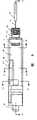
图1为按照本发明较佳的SC实施例的连接器前上左方立体图;Fig. 1 is a front upper left perspective view of a connector according to a preferred SC embodiment of the present invention;
图2为图1中连接器的后上右方立体图;Fig. 2 is a rear upper right perspective view of the connector in Fig. 1;
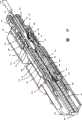
图3为图2中连接器分解立体图;Fig. 3 is an exploded perspective view of the connector in Fig. 2;
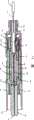
图4为图3中SC组件分解立体图;Fig. 4 is an exploded perspective view of the SC assembly in Fig. 3;
图4A为图4中缓冲夹子放大立体图;Fig. 4A is an enlarged perspective view of the buffer clip in Fig. 4;
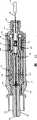
图5为图4中SC组件一部分放大分解立体图;Fig. 5 is an enlarged exploded perspective view of a part of the SC assembly in Fig. 4;
图6为图5中凸轮正视图;Fig. 6 is a front view of the cam in Fig. 5;
图7为图5中所示凸轮以外的SC组件部分未分解前下右方立体图;Fig. 7 is a front, bottom, right perspective view of the parts of the SC assembly other than the cam shown in Fig. 5;
图8为图4中SC组件在组装状态顶视平面图;Fig. 8 is a top plan view of the SC assembly in Fig. 4 in an assembled state;
图9为图8中SC组件右侧视图;Figure 9 is a right side view of the SC assembly in Figure 8;
图10为图8中SC组件剖视立体图;Fig. 10 is a sectional perspective view of the SC assembly in Fig. 8;
图11为图8中SC组件沿图8中11-11线剖面图;Fig. 11 is a sectional view of the SC assembly in Fig. 8 along line 11-11 in Fig. 8;
图12为图9中SC组件沿图9中12-12线剖面图;Fig. 12 is a sectional view of the SC assembly in Fig. 9 along line 12-12 in Fig. 9;
图13为图9中SC组件沿图9中13-13线剖面图;Fig. 13 is a sectional view of the SC assembly in Fig. 9 along line 13-13 in Fig. 9;
图14为图9中SC组件沿图9中14-14线剖面图;Fig. 14 is a sectional view of the SC assembly in Fig. 9 along line 14-14 in Fig. 9;
图15为图9中SC组件沿图9中15-15线剖面图;Fig. 15 is a sectional view of the SC assembly in Fig. 9 along line 15-15 in Fig. 9;
图16为图9中附有螺帽和防护罩的SC组件前上右方立体图;Fig. 16 is a front upper right perspective view of the SC assembly with a nut and a protective cover in Fig. 9;
图17为图16中组件右侧剖面视图;Fig. 17 is a sectional view on the right side of the assembly in Fig. 16;
图18为图17中组件部分剖开近视图;Figure 18 is a close-up view of part of the assembly in Figure 17;
图19为图17中组件按照图18中19-19线剖面图;Fig. 19 is a sectional view of the assembly in Fig. 17 according to line 19-19 in Fig. 18;
图20为图17中组件按照图17中20-20线剖面图;Fig. 20 is a sectional view of the assembly in Fig. 17 according to line 20-20 in Fig. 17;
图21为按照本发明较佳FJ插座实施例的连接器前上右方立体图;Fig. 21 is a front upper right perspective view of the connector according to a preferred FJ socket embodiment of the present invention;
图22为图21中连接器后上右方立体图;Figure 22 is a perspective view of the rear upper right side of the connector in Figure 21;
图23为图22中连接器分解图;Figure 23 is an exploded view of the connector in Figure 22;
图24为图23的倒视图;Fig. 24 is the reverse view of Fig. 23;
图25为图23的另一分解图;Fig. 25 is another exploded view of Fig. 23;
图26为图21中连接器前下右方分解立体图;Figure 26 is an exploded perspective view of the connector in Figure 21 at the front, bottom, and right side;
图27为图21中连接器顶视平面图;Figure 27 is a top plan view of the connector in Figure 21;
图28为图27中连接器右侧视图;Figure 28 is a right side view of the connector in Figure 27;
图29为图27中连接器按照图27中29-29线剖面图;Fig. 29 is a sectional view of the connector in Fig. 27 according to line 29-29 in Fig. 27;
图30为图28中连接器沿图28中30-30线剖面图;Fig. 30 is a sectional view of the connector in Fig. 28 along line 30-30 in Fig. 28;
图31为图28中连接器沿图28中31-31线剖面图;Fig. 31 is a sectional view of the connector in Fig. 28 along line 31-31 in Fig. 28;
图32为图28中连接器沿图28中32-32线剖面图;Fig. 32 is a sectional view of the connector in Fig. 28 along line 32-32 in Fig. 28;
图33为图21中连接器FJ组件部分后上右方分解立体图;Fig. 33 is an exploded perspective view of the rear upper right side of the connector FJ assembly part in Fig. 21;
图34为图33中组件的视图,其中一个组件已经放入FJ帽;Figure 34 is a view of the components in Figure 33, one of which has been placed into the FJ cap;
图35为图34中组件前上左方立体图;Fig. 35 is a front upper left perspective view of the assembly in Fig. 34;
图36为类似图34的视图,其中组件已放入FJ帽并且与FJ壳体对准;和Figure 36 is a view similar to Figure 34 with the assembly placed into the FJ cap and aligned with the FJ housing; and
图37为类似图36的视图,其中连接器已经装配完全。Figure 37 is a view like Figure 36 with the connector fully assembled.
具体实施方式Detailed ways
本发明一般涉及光学纤维连接器并且更具体地涉及预先抛光的纤维梢头连接器。The present invention relates generally to fiber optic connectors and more particularly to pre-polished fiber stub connectors.
如在图1、2和图3的分解图中可见,可逆和非破坏性光学纤维梢头连接器10的较佳实施例用来连接现场纤维。连接器10包括一般封装具有干线(backbone)14的SC组件13的外部壳体12。现场纤维16通过干线插入连接器,而具有防护罩18和保持螺帽86的防护罩/螺帽组件包围并支承光缆护套19和围绕纤维16的缓冲部分20。较佳地也可在光缆护套和缓冲部分之间设置凯夫拉纤维21,虽然在某些实施例中,现场纤维可以只有缓冲部分而没有光缆护套或凯夫拉纤维。As seen in the exploded views of FIGS. 1, 2 and 3, a preferred embodiment of a reversible and non-destructive fiber
如在图4及5中可见,SC组件具有含有中空套箍夹持器24和凸轮26的内部壳体22。套箍夹持器具有围绕套箍30一端的套箍接受部分28,凸缘部分32,具有凸脊槽36的大套筒部分34,具有接受缓冲夹子41的夹子槽40的中套筒部分38,和在一端具有开口的小套筒部分42。凸轮套筒26包括具有向外延伸杠杆48的大套筒部分46和小套筒部分50。在凸轮26的大套筒部分46内有大内部凸轮表面52,和在凸轮26的小套筒部分50内有小内部凸轮表面53,凸轮表面从凸轮中心(凸轮同轴套筒部分的轴线)具有变化的半径。虽然如在图6中可见,各凸轮表面52及53的较大和较小半径一般在角度上对准,但并不要求它们如此对准,按照其它连接器部件的位置和方向,可以并不如此对准。As can be seen in FIGS. 4 and 5 , the SC assembly has an
还可以在这些分解图中看到,连接器所显示的实施例包括一对支撑板,即夹持板54和v形槽板56。支撑板54和56通过套箍夹持器24的套箍接受部分28和凸缘部分32插入而进入其大套筒部分34,协力地在其中形成沟槽。在所示实施例中,沟槽57一般在v形槽板56中出现并且当二板合拢时与夹持板54齐平。二板的两端较佳地具有锥形的引入部分58以便当二板合拢时方便纤维插入沟槽。夹持板54包括向外延伸的凸脊55,用于从大套筒部分34的凸脊槽36中突出。It can also be seen in these exploded views that the illustrated embodiment of the connector includes a pair of support plates, clamping
一旦各板插入套箍夹持器的大套筒部分,套箍30和其相关的纤维梢头60被插入套箍夹持器24的套箍接受部分28。纤维梢头60从套箍30延伸进入在板54及56之间的前引入部分58和沟槽57。各板一般对套箍30齐平,并且虽然板的前端一般靠近套箍夹持器24的套箍接受部分28和凸缘部分32之间的接口,板的主要部分设置在大套筒部分34以内。如果纤维在进入中没有很好地与沟槽对准,在板的梢头一侧的锥形引入部分58可较佳地防止纤维梢头精确劈开端被损坏。Once the plates are inserted into the large sleeve portion of the ferrule holder, the
在图4A中可详细地看到,缓冲夹子41较佳地为整体的并包括环形部分62和杆身部分64。沿杆身长度的中途,较佳地设置在一端具有凸轮随动表面68和在另一端具有握持部分70的横向部分66。在本发明较佳实施例中,握持部分为倾斜的以便为纤维引入提供方便,使缓冲部分在插入时不致被卡住。也在较佳实施例中,握持端包括可握持通过夹子槽40缓冲部分的齿71。缓冲夹子41通过环形部分62围绕(即夹住)小套筒部分42的一端而施加于套箍夹持器24,接着升起到中套筒部分38处,使杆身部分64可以配合进入中套筒部分38的夹子槽40中。As seen in detail in FIG. 4A , the
凸轮26在套箍夹持器24的3个套筒部分34、38及42上滑动,直到其与凸缘部分32齐平。假设夹持板54的凸脊55通过大套筒部分34的凸脊槽36突出并且和其缓冲夹子41的横向部分66凸轮随动表面68从中套筒部分38的夹子槽40中突出,当凸轮26滑过套箍夹持器24时,将不得不适当地在角度上定位,使内部凸轮表面52及53各自的较大半径配合这些突出的元件并且不干涉它们,免使凸轮套管不能施加在套箍夹持器上。The
弹簧72配合在凸轮26的小套筒部分50的外面并且在套箍后面提供压缩阻力,使得当连接器与适当孔口或其它连接器配对时,在各套箍或套箍30和孔口上接触点之间可以获得良好的接触压力。套筒部分76上的凸片78为锥形以便容许干线14压入孔内,使锥形凸片在插入中迫使分裂的壳体分开并容许在凸片过去以后壳体可以弹性地缩回原状。凸片较佳地把干线保留在内部壳体内。外螺蚊部分80从孔74突出。A
SC组件13较佳地在工厂中制造以便使用连接器的现场操作者可以预先装配光学纤维连接。这样可限制在现场执行装配所需工作量。为用预先装配的连接器连接现场纤维`16,光缆护套19较佳地从缓冲部分剥去一段预定长度,如图4所示。较佳地与防护罩18一起预先装配的保持螺帽86被滑上现场纤维16的一端,使纤维从螺帽突出。保持螺帽86的套筒部分90具有内螺纹,使其可以在现场纤维连接以后旋入干线14的外螺纹部分80。纤维的端部然后较佳地精确地劈开使其可以更清洁地接合纤维梢头60。The
现场纤维通过干线14的外部螺纹部分80、通过小套筒部分42和中套筒部分38插入并进入套箍夹持器24的大套筒部分34内、板54及56之间的引入部分58和沟槽57。现场纤维被插入直到其端部大约在板的长度一半和大约夹持板54上沿凸脊55长度一半之处接触纤维梢头60。可以较佳地在沟槽的后半部施加折射率匹配凝胶,以便当现场纤维一旦适当地对准后在折射上限制在现场纤维和纤维梢头接触面处的信号损失。The field fiber is inserted through the external threaded
一旦操作者确定纤维端部已经接触,他用手旋转从内部壳体22开放部分突出凸轮26的杠杆48。凸轮的旋转促使大内部第一凸轮表面52绷紧从夹持板54通过大套筒部分34的凸脊槽36突出的凸脊55。这促使板54及56沿它们邻接表面和沟槽互相挤压,从而压缩纤维梢头端部和现场纤维端部沿沟槽57长度夹持在其位置上,并且更好地在沟槽内它们的接口处对准。在此同时,小内部第二凸轮表面53在缓冲夹子41凸轮随动表面68上绷紧,从而促使其握持部分70压紧缓冲部分20,并且对现场纤维提供应消除和抑制任何拉动梢头和现场纤维端部在沟槽中互相离开的企图。此外,缓冲夹子的齿71抑制内部缓冲层和纤维的旋转运动。Once the operator has determined that the fiber ends have made contact, he manually rotates the
在连接方法中通过局部测试装置,诸如可见故障定位器(VFL),可以施行测试。因为没有实行可逆和/或破坏性卷曲、连接或应变消除措施,如果测试证明光学纤维连接(或即使是机械连接)是足够的,整个连接方法通过用手旋转凸轮26的杠杆返回其原来的位置是完全非破坏性地可逆的。这同时释放在凸脊55(并且从而在板54及56)上的压力并且释放在缓冲部分上缓冲夹子41的压缩。如此,现场纤维可以简单地被旋转或在重新夹紧连接器前另外移动并且再一次决定连接是否已经成功地完成。可选地,现场纤维可以从在该点上从连接器抽出,随意地重新劈开,并且随后重新插入以便再作一次成功连接的企图。关于在此使用的名词“同时”,在本发明上下文范围内不需要实际时序上的符合,该名词一般涉及在同样时间发生的行动和/或由于同样触发事件引起的行动。Testing can be carried out in the connection method by means of local test devices, such as visible fault locators (VFL). Since no reversible and/or destructive crimping, connection or strain relief is practiced, if testing proves that a fiber optic connection (or even a mechanical connection) is adequate, the entire method of connection is returned to its original position by manually rotating the lever of the
然后内部壳体22的前端82插入外部壳体12的口部,直到内部壳体完全吞没在外部壳体中,并且在内部壳体外面和外部壳体里面的补充结构互相接合,使内部壳体保留在外部壳体中。凸轮26的杠杆48较佳地需要旋转到特定的角度方位,以便促进套箍夹持器24和凸轮26进入壳体22(以形成SC组件13),并且随后进一步促进SC组件13插入外部壳体12。内部壳体22较佳地在凸轮完全作用之处限制杠杆继续旋转。一旦SC组件13插入外部壳体12,杠杆48将较佳地在套箍夹持器和外部壳体之间在角度方面固定。The
总之,操作者只需要适当地剥离现场纤维,将其插入组件中,旋转凸轮26的杠杆48形成连接并在缓冲部分消除应变,用局部测试装置确认连接成功,并然后把组件插入外部壳体12和在干线14的外部螺纹部分80上旋入保持螺帽86。In summary, the operator only needs to properly strip the field fiber, insert it into the assembly, rotate the
在成功地连接现场纤维和预先装配的纤维梢头连接器以后,连接器可以插入在修补面板上适当的配置口或其它装置,使较佳地抛光的套箍30前端面84和相似地抛光的纤维梢头前端面可以在装置中界面连接并且容许信号从现场纤维通过到装置或反之。After successfully connecting the field fiber and the pre-assembled fiber stub connector, the connector can be inserted into a suitable configuration port or other device in the repair panel, allowing the preferably polished
在本发明连接器和采用的方法众多特征中最有利的是其在连接中的完全可逆性。虽然可逆旋转杠杆过去曾用来实行和释放在光学纤维连接器(诸如在EP1136860)中的对准,这样的连接器不能提供同时的缓冲部分夹紧和脱开。这样,这些连接器一般需要额外和对缓冲部分不可逆的(即,破坏性的)卷曲,以便对于对准的现场和梢头纤维之间接口提供有益的应变消除。通常这样的卷曲步骤可能降低纤维接口的品质,但由于卷曲是不可逆的,无法显著地改善降级的连接,除非切去浪费的连接器、重新剥离和劈开纤维和重新连接现场纤维和在新的连接器中的梢头纤维。按照本发明的连接器可以免去对于这样不可逆和破坏性缓冲部分卷曲的需要,而只需要更一般性的卷曲。Most advantageous among the many features of the inventive connector and the method employed is its complete reversibility in connection. While reversible rotating levers have been used in the past to effect and release alignment in fiber optic connectors (such as in EP1136860), such connectors do not provide simultaneous clamping and unclamping of the buffer portion. As such, these connectors generally require additional and irreversible (ie, destructive) crimping of the buffer portion in order to provide beneficial strain relief for the interface between the aligned field and tip fibers. Usually such a crimping step may degrade the quality of the fiber joint, but since crimping is irreversible, it cannot significantly improve the degraded connection unless the wasted connector is cut away, the fiber is re-stripped and split and the fiber is reconnected on-site and in a new Tip fibers in connectors. Connectors according to the present invention can eliminate the need for such irreversible and destructive cushioning crimping, requiring only more general crimping.
在本发明范围内考虑可以同时对准/连接纤维而仍可对缓冲部分提供应变消除作用的可逆促动器,可以基本上区分为两种单独的促动器,一种用来对准/连接纤维而另一种用来对缓冲部分提供可逆和非破坏性的应变消除。虽然这样的对准可能牵涉到在接合连接器时额外的步骤,按照这两种动作是否可以均在一个额外步骤中转换,功能或成本效益可以从这些功能独立地实行而仍保持在缓冲部分上提供的应变消除的非破坏性和可逆性而确定。虽然图中所示可逆促动器为凸轮,任何形式的可逆的促动器,例如开关,也可在本发明范围内考虑采用。It is contemplated within the scope of this invention that reversible actuators that can simultaneously align/join fibers while still providing strain relief to the cushioning portion can basically be distinguished as two separate actuators, one for aligning/joining The fiber and the other are used to provide reversible and non-destructive strain relief to the cushioning section. Although such an alignment may involve an extra step in engaging the connector, depending on whether both actions can be switched in one extra step, functions or cost benefits can be achieved independently from these functions while still remaining on the buffer portion Determined by the non-destructive and reversible nature of the strain relief provided. Although the reversible actuator is shown as a cam, any form of reversible actuator, such as a switch, is contemplated within the scope of the present invention.
本发明可以用不同于上面披露的SC型光学插头的形式实施,而图21-37显示本发明可供选择的实施例,其中连接器一般配置为FJ-型光学插头。还有可能在发明中采用诸如符合SC、LC、ST或FJ标准的插头或插座的形式。The present invention may be implemented in forms other than the SC-type optical plugs disclosed above, and Figures 21-37 show an alternative embodiment of the invention in which the connector is generally configured as an FJ-type optical plug. It is also possible in the invention to take the form of, for example, plugs or sockets conforming to SC, LC, ST or FJ standards.
如图25及26中具体地可见,图21-37中FJ插座110基本上采用两个全同于在以上描述的SC型插头连接器的SC组件,并带有附加匹配FJ标准的部件。与在SC连接器中相应零件相比,FJ实施例中的相同另件增加编号100,两个组件113并排地放入FJ帽190中。两套箍130被分开的套管191所包围,其中套管由分开的套管保持件192夹持在位。套箍和所附属的分开套管配合在FJ壳体194的套箍开口193中。保持件192较佳地可以包括用于配合进入套箍开口193的沟槽196的凸片195。配合在组件113上的帽190的前面边缘197,当分开的套管套箍130完全插入开口193时,一般将较佳地与FJ壳体194后面部分198齐平。FJ壳体194包括凹陷的前面部分199为套箍130的较佳地抛光的前表面184提供接近便利,以便接受和匹配相应配置的FJ插头型连接器或其它兼容的连接器。与SC实施例相比内部壳体122的前端182可以包括较少的锁扣机构,因为FJ帽190和壳体194取代锁住外部壳体(诸如外部壳体12)的需要。其它在帽和壳体上的锁扣可以用来帮助保持部件。在帽上可以较佳地设置凸脊189以便帮助用手握持帽和连接器。As can be seen particularly in FIGS. 25 and 26, the
本发明FJ插座的实施例保留以前描述的关于SC插头方案中完全可逆的优点,由于两个光学纤维连接均可通过旋转杠杆148而完全可逆。此外,假定它们在FJ帽和壳体内并排地放置,杠杆148在凸轮上的旋转和角度放置可以有利地如此定位,即只有当杠杆旋转到关闭位置(即,纤维对准)时,组件才可以插入帽和壳体。FJ插座110的另一个优点是套箍130可以浮动在弹簧172上,以便当插座接合插头或其它连接硬件时可以提供接触压力。The FJ jack embodiment of the present invention retains the previously described advantage of full reversibility in relation to the SC plug solution, since both fiber optic connections are fully reversible by rotating the
本发明以上阐明和描述的实施例仅为代表性的并且无论如何不打算限制发明的范围。相反,本发明认为可以包括并没在这里具体显示和描述的方案。例如,缓冲部分夹子可以具有在结构上不同于图4A所显示的握持部分,它将认为属于本发明范围以内。相似地,以不同方式接合缓冲部分而提供应变消除的缓冲部分夹子也将认为属于本发明范围内。还有,缓冲部分不必包括任何具体类型的材料并且不同类型的包围材料可以在本发明各种实施例中交替地出现。此外,本发明不限于这里描述和阐明的具体SC和FJ光学格式,因为本发明可以在其它当前或甚至尚未存在的光学格式中采用。相似地,本发明可以在类似插头或类似插座/接受器的连接器中采用,因为阳/阴结构一般不阻碍本发明的使用。本发明由下列权利要求所限定。The above illustrated and described embodiments of the invention are representative only and are not intended to limit the scope of the invention in any way. On the contrary, the invention is contemplated to include aspects not specifically shown and described herein. For example, the cushioning portion clip could have a grip portion that is structurally different than that shown in FIG. 4A and it would be considered within the scope of the present invention. Similarly, bumper clips that engage the bumper in a different manner to provide strain relief are also considered to be within the scope of the present invention. Also, the cushioning portion need not include any particular type of material and different types of surrounding materials may alternate in various embodiments of the invention. Furthermore, the invention is not limited to the specific SC and FJ optical formats described and illustrated herein, as the invention may be employed in other current or even non-existing optical formats. Similarly, the present invention can be employed in plug-like or receptacle/receptacle-like connectors, since the male/female configuration generally does not prevent the use of the present invention. The invention is defined by the following claims.
Claims (41)
Applications Claiming Priority (2)
| Application Number | Priority Date | Filing Date | Title |
|---|---|---|---|
| US10/647,848 | 2003-08-25 | ||
| US10/647,848US7011454B2 (en) | 2003-08-25 | 2003-08-25 | Reversible fiber optic stub fiber connector |
Related Child Applications (1)
| Application Number | Title | Priority Date | Filing Date |
|---|---|---|---|
| CNA200910002923XADivisionCN101458367A (en) | 2003-08-25 | 2004-08-25 | Reversible fiber optic connector |
Publications (2)
| Publication Number | Publication Date |
|---|---|
| CN1607411A CN1607411A (en) | 2005-04-20 |
| CN100465678Ctrue CN100465678C (en) | 2009-03-04 |
Family
ID=34136614
Family Applications (2)
| Application Number | Title | Priority Date | Filing Date |
|---|---|---|---|
| CNB2004100685310AExpired - LifetimeCN100465678C (en) | 2003-08-25 | 2004-08-25 | Reversible optical fiber connector |
| CNA200910002923XAPendingCN101458367A (en) | 2003-08-25 | 2004-08-25 | Reversible fiber optic connector |
Family Applications After (1)
| Application Number | Title | Priority Date | Filing Date |
|---|---|---|---|
| CNA200910002923XAPendingCN101458367A (en) | 2003-08-25 | 2004-08-25 | Reversible fiber optic connector |
Country Status (4)
| Country | Link |
|---|---|
| US (8) | US7011454B2 (en) |
| JP (1) | JP4498066B2 (en) |
| CN (2) | CN100465678C (en) |
| TW (1) | TWI350391B (en) |
Cited By (1)
| Publication number | Priority date | Publication date | Assignee | Title |
|---|---|---|---|---|
| US9423586B2 (en) | 2011-10-25 | 2016-08-23 | Corning Cable Systems (Shanghai) Co., Ltd. | Fiber optic connectors, cable assemblies and method for making the same |
Families Citing this family (132)
| Publication number | Priority date | Publication date | Assignee | Title |
|---|---|---|---|---|
| KR100529872B1 (en)* | 1998-09-09 | 2005-11-22 | 동경 엘렉트론 주식회사 | Developing method and developing apparatus |
| US9239441B2 (en) | 2000-05-26 | 2016-01-19 | Corning Cable Systems Llc | Fiber optic drop cables and preconnectorized assemblies having toning portions |
| US7467896B2 (en)* | 2000-05-26 | 2008-12-23 | Corning Cable Systems Llc | Fiber optic drop cables and preconnectorized assemblies |
| US7113679B2 (en)* | 2000-05-26 | 2006-09-26 | Corning Cable Systems, Llc | Fiber optic drop cables and preconnectorized assemblies having toning portions |
| JP2004503814A (en) | 2000-06-12 | 2004-02-05 | クローネ ゲーエムベーハー | Assembly and method for use in terminating optical fibers |
| US7011454B2 (en)* | 2003-08-25 | 2006-03-14 | Panduit Corp. | Reversible fiber optic stub fiber connector |
| US6962445B2 (en) | 2003-09-08 | 2005-11-08 | Adc Telecommunications, Inc. | Ruggedized fiber optic connection |
| US7290941B2 (en)* | 2003-12-23 | 2007-11-06 | Amphenol Corporation | Modular fiber optic connector system |
| JP2005189332A (en)* | 2003-12-24 | 2005-07-14 | Three M Innovative Properties Co | Optical connector, optical fiber with connector, optical fiber connecting apparatus and method for connecting optical fiber |
| US7204644B2 (en)* | 2004-03-24 | 2007-04-17 | Corning Cable Systems Llc | Field installable optical fiber connector |
| US7104702B2 (en) | 2004-03-24 | 2006-09-12 | Corning Cable Systems Llc | Field installable optical fiber connector |
| US20060002662A1 (en)* | 2004-06-30 | 2006-01-05 | Tyco Electronics Corporation | Small form factor, field-installable connector |
| US7331719B2 (en)* | 2004-06-30 | 2008-02-19 | Tyco Electronics Corporation | Optical fiber clamping assembly |
| JP4544928B2 (en)* | 2004-07-16 | 2010-09-15 | スリーエム イノベイティブ プロパティズ カンパニー | Optical connector and optical fiber connection system |
| JP4416591B2 (en)* | 2004-07-16 | 2010-02-17 | スリーエム イノベイティブ プロパティズ カンパニー | Optical connector and optical fiber connection system |
| FR2873453B1 (en)* | 2004-07-26 | 2006-11-24 | Nexans Sa | CONNECTOR FOR OPTICAL FIBER |
| US7333709B2 (en)* | 2004-09-24 | 2008-02-19 | 3M Innovative Properties Company | Splice holder device |
| US7346256B2 (en)* | 2004-11-04 | 2008-03-18 | Panduit Corp. | Re-terminable LC connector assembly and cam termination tool |
| US7192195B2 (en) | 2005-07-29 | 2007-03-20 | Corning Cable Systems Llc | Methods and apparatus for estimating optical insertion loss |
| WO2007050470A1 (en)* | 2005-10-24 | 2007-05-03 | 3M Innovative Properties Company | Optical connector, fiber distribution unit, and fiber termination platform for optical connectors |
| JP4942327B2 (en)* | 2005-10-28 | 2012-05-30 | スリーエム イノベイティブ プロパティズ カンパニー | Optical connector |
| JP4660351B2 (en)* | 2005-10-31 | 2011-03-30 | スリーエム イノベイティブ プロパティズ カンパニー | Optical connector |
| WO2007053660A1 (en)* | 2005-11-01 | 2007-05-10 | Molex Incorporated | Locking mechanism for optical tranceivers |
| US7393148B2 (en)* | 2005-12-06 | 2008-07-01 | Tyco Electronics Corporation | Optical fiber splicing closures and methods |
| US8094988B2 (en)* | 2005-12-15 | 2012-01-10 | Corning Cable Systems Llc | Apparatus and methods for verifying an acceptable splice termination |
| US7680384B2 (en) | 2006-01-26 | 2010-03-16 | Corning Cable Systems Llc | Installation tool with integrated visual fault indicator for field-installable mechanical splice connector |
| US7658553B2 (en) | 2006-03-14 | 2010-02-09 | Corning Cable Systems Llc | Mechanical splice connector with sequential splice and strain relief |
| US7264410B1 (en) | 2006-03-16 | 2007-09-04 | Corning Cable Systems Llc | Dual function splice component for mechanical splice connector |
| US7466891B2 (en)* | 2006-06-13 | 2008-12-16 | Panduit Corp. | Activation tool for a fiber optic connector |
| US7241056B1 (en) | 2006-06-13 | 2007-07-10 | Panduit Corp. | Reversible fiber optic connector |
| US7572064B2 (en)* | 2006-07-24 | 2009-08-11 | Corning Cable Systems Llc | Optical fiber mechanical splice connector |
| US7591595B2 (en)* | 2007-01-24 | 2009-09-22 | Adc Telelcommunications, Inc. | Hardened fiber optic adapter |
| US7572065B2 (en) | 2007-01-24 | 2009-08-11 | Adc Telecommunications, Inc. | Hardened fiber optic connector |
| US7775726B2 (en)* | 2007-02-16 | 2010-08-17 | 3M Innovative Properties Company | Remote grip optical fiber connector |
| EP2115508A1 (en) | 2007-02-16 | 2009-11-11 | 3M Innovative Properties Company | Remote grip optical fiber connector |
| US7455460B2 (en)* | 2007-03-08 | 2008-11-25 | Panduit Corp. | Fiber optic connector with double-clad stub fiber |
| GB2448935B8 (en)* | 2007-05-04 | 2010-08-25 | Miniflex Ltd | Opticle fibre connector |
| US7785017B2 (en)* | 2007-09-27 | 2010-08-31 | Corning Cable Systems Llc | Strain-relief assemblies and methods for a field-installable fiber optic connector |
| US7513695B1 (en)* | 2007-10-09 | 2009-04-07 | Protai Photonic Co., Ltd. | Small form factor, field-installable optical fiber connector |
| US7762726B2 (en)* | 2007-12-11 | 2010-07-27 | Adc Telecommunications, Inc. | Hardened fiber optic connection system |
| US8403570B2 (en)* | 2008-04-10 | 2013-03-26 | Amphenol Corporation | Plural fiber optic interconnect |
| MX2010012852A (en)* | 2008-05-29 | 2010-12-21 | Panduit Corp | Method and apparatus for verifying the termination quality of an optical fiber interface in a fiber optic cable connector. |
| EP3171208A1 (en)* | 2008-06-06 | 2017-05-24 | 3M Innovative Properties Company | Field terminable optical fiber connector with splice element |
| US7887244B2 (en)* | 2008-06-13 | 2011-02-15 | Belden Cdt (Canada) Inc. | Reversible fiber connector with mechanical splice and sliding lock |
| US8075198B2 (en)* | 2008-06-23 | 2011-12-13 | Belden Cdt (Canada) Inc. | Reversible fiber connector with mechanical sliding splice |
| US8376631B2 (en) | 2008-08-19 | 2013-02-19 | Belden Cdt (Canada) Inc. | Slide actuated field installable fiber optic connector |
| US7811006B2 (en)* | 2008-09-02 | 2010-10-12 | Belden CD (Canada) Inc. | Field installable fiber optic connector and installation tool |
| CN102414593B (en)* | 2009-04-23 | 2014-09-24 | 3M创新有限公司 | Collar Bodies for Field-Terminable Optical Connectors |
| WO2010129785A1 (en)* | 2009-05-08 | 2010-11-11 | Adc Telecommunications, Inc. | Cable pulling assembly |
| JP2010277999A (en)* | 2009-06-01 | 2010-12-09 | Korea Electronics Telecommun | Dye-sensitized solar cell and manufacturing method thereof |
| WO2011025637A1 (en)* | 2009-08-31 | 2011-03-03 | Corning Cable Systems Llc | Termination tool and methods therefor |
| JP5401274B2 (en)* | 2009-11-20 | 2014-01-29 | 株式会社フジクラ | Optical transmission body with connector, optical connector, and optical connector assembly method |
| WO2011087942A1 (en)* | 2010-01-15 | 2011-07-21 | Corning Cable Systems Llc | An optical fiber stripper for a fiber optic connection termination system |
| CA2784804A1 (en)* | 2010-01-15 | 2011-07-21 | Corning Cable Systems Llc | Optical fiber handler for a fiber optic connection termination system |
| EP2524254A1 (en)* | 2010-01-15 | 2012-11-21 | Corning Cable Systems LLC | Fiber optic connector of a fiber optic connection termination system |
| CN102141655B (en)* | 2010-02-01 | 2013-07-03 | 鸿富锦精密工业(深圳)有限公司 | Optical fiber connector |
| US8388242B2 (en) | 2010-05-19 | 2013-03-05 | Adc Telecommunications, Inc. | In-line splice with integrated splice holder |
| CN101986177B (en)* | 2010-08-31 | 2012-04-25 | 深圳日海通讯技术股份有限公司 | Device for assembling through-type fiber on-spot connector |
| JP5707600B2 (en)* | 2010-09-22 | 2015-04-30 | 住友電工デバイス・イノベーション株式会社 | Optical module and optical module manufacturing method |
| US8753022B2 (en) | 2010-11-30 | 2014-06-17 | Adc Telecommunications, Inc. | LC connector and method of assembly |
| US8702323B2 (en)* | 2011-03-15 | 2014-04-22 | Adc Telecommunications, Inc. | Strain relief boot for a fiber optic connector |
| US8734028B2 (en)* | 2011-05-25 | 2014-05-27 | Tyco Electronics Corporation | Tool-less clamping mechanism |
| CN202995082U (en) | 2011-06-27 | 2013-06-12 | 3M创新有限公司 | Optical fiber connector for terminating optical fibers |
| US8596884B2 (en) | 2011-06-28 | 2013-12-03 | Corning Cable Systems Llc | Optical fiber mechanical splice connector systems and methods of coupling optical fibers |
| EP2726923A4 (en)* | 2011-06-30 | 2015-04-15 | Corning Cable Systems Shanghai Co Ltd | Fiber optic connectors,cable assemblies and method for making the same |
| KR101248591B1 (en)* | 2011-10-24 | 2013-03-28 | 주식회사 옵텔콤 | Cable gripping device, and optical connector having the same |
| JP2013142858A (en)* | 2012-01-12 | 2013-07-22 | Hitachi Cable Ltd | Ferrule holding member and optical connector |
| US10310208B2 (en) | 2012-02-13 | 2019-06-04 | Cable Corning Systems LLC | Fiber optic cable sub-assemblies and methods of making |
| CN103364883B (en)* | 2012-04-09 | 2015-04-15 | 鸿富锦精密工业(深圳)有限公司 | Optical fiber connector |
| WO2013177016A1 (en)* | 2012-05-22 | 2013-11-28 | Adc Telecommunications, Inc. | Ruggedized fiber optic connector |
| US8939655B2 (en) | 2012-06-29 | 2015-01-27 | Corning Cable Systems Llc | Dust caps, fiber optic connectors, and fiber optic splitter modules incorporating interlocking key features |
| US9146362B2 (en) | 2012-09-21 | 2015-09-29 | Adc Telecommunications, Inc. | Insertion and removal tool for a fiber optic ferrule alignment sleeve |
| US9052469B2 (en) | 2013-04-26 | 2015-06-09 | Corning Cable Systems Llc | Preterminated fiber optic connector sub-assemblies, and related fiber optic connectors, cable assemblies, and methods |
| WO2014206976A1 (en) | 2013-06-27 | 2014-12-31 | Tyco Electronics Raychem Bvba | Fiber optic cable anchoring device for use with fiber optic connectors and methods of using the same |
| AU2014293291B2 (en) | 2013-07-22 | 2018-06-14 | Commscope Asia Holdings B.V. | Expanded beam fiber optic connector, and cable assembly, and methods for manufacturing |
| CA2919003A1 (en)* | 2013-07-22 | 2015-01-29 | Adc Telecommunications, Inc. | Fiber optic cable and connector assembly including integrated enhanced functionality |
| WO2015095872A1 (en)* | 2013-12-20 | 2015-06-25 | Afl Telecommunications Llc | Splice-on optical connector for outside plant drop cable |
| US9297964B2 (en)* | 2014-04-18 | 2016-03-29 | Senko Advanced Components, Inc. | Optical fiber connector assembly |
| CN104007516A (en)* | 2014-04-30 | 2014-08-27 | 奉化市宇达高科光电器件有限公司 | Saucer-shaped optical fiber quick connector |
| CN105445863B (en) | 2014-07-25 | 2017-09-26 | 鸿富锦精密工业(深圳)有限公司 | Joints of optical fibre assemble method |
| CN105278049B (en)* | 2014-07-25 | 2018-02-06 | 鸿富锦精密工业(深圳)有限公司 | The joints of optical fibre |
| AU2016222612B2 (en) | 2015-02-25 | 2021-08-05 | Ppc Broadband, Inc. | Connectors for micro-duct terminations of fiber optic cable |
| DE102015105514A1 (en)* | 2015-04-10 | 2016-10-13 | Voith Patent Gmbh | Device for transmitting data and / or signals |
| MX2017014377A (en) | 2015-05-15 | 2018-08-15 | Adc Telecommunications Shanghai Distrib Co Ltd | Alignment sleeve assembly and optical fibre adapter. |
| JP6567093B2 (en)* | 2015-06-11 | 2019-08-28 | コリア レイルロード リサーチ インスティテュート | Foldable container |
| MX387864B (en)* | 2016-01-12 | 2025-03-19 | Corning Optical Communications LLC | HARDENED FIBER OPTIC CONNECTORS THAT HAVE A MECHANICAL ASSEMBLY OF THE SPLICE CONNECTOR. |
| US10156683B2 (en) | 2016-04-11 | 2018-12-18 | Leviton Manufacturing Co., Inc. | Polarity identification for polarity reversing duplex unibody connectors |
| US9946035B2 (en)* | 2016-04-11 | 2018-04-17 | Leviton Manufacturing Co., Inc. | Fiber optic connector |
| US10754098B2 (en)* | 2017-04-07 | 2020-08-25 | Senko Advanced Components, Inc. | Behind the wall optical connector with reduced components |
| US10359577B2 (en) | 2017-06-28 | 2019-07-23 | Corning Research & Development Corporation | Multiports and optical connectors with rotationally discrete locking and keying features |
| US11300746B2 (en) | 2017-06-28 | 2022-04-12 | Corning Research & Development Corporation | Fiber optic port module inserts, assemblies and methods of making the same |
| US12271040B2 (en) | 2017-06-28 | 2025-04-08 | Corning Research & Development Corporation | Fiber optic extender ports, assemblies and methods of making the same |
| CN111051945B (en) | 2017-06-28 | 2023-12-29 | 康宁研究与开发公司 | Compact fiber optic connector, cable assembly and method of making the same |
| US11668890B2 (en) | 2017-06-28 | 2023-06-06 | Corning Research & Development Corporation | Multiports and other devices having optical connection ports with securing features and methods of making the same |
| US11187859B2 (en) | 2017-06-28 | 2021-11-30 | Corning Research & Development Corporation | Fiber optic connectors and methods of making the same |
| US11822133B2 (en) | 2017-07-14 | 2023-11-21 | Senko Advanced Components, Inc. | Ultra-small form factor optical connector and adapter |
| US12001064B2 (en) | 2017-07-14 | 2024-06-04 | Senko Advanced Components, Inc. | Small form factor fiber optic connector with multi-purpose boot |
| US10281669B2 (en) | 2017-07-14 | 2019-05-07 | Senko Advance Components, Inc. | Ultra-small form factor optical connectors |
| US10718911B2 (en) | 2017-08-24 | 2020-07-21 | Senko Advanced Components, Inc. | Ultra-small form factor optical connectors using a push-pull boot receptacle release |
| US11002923B2 (en) | 2017-11-21 | 2021-05-11 | Senko Advanced Components, Inc. | Fiber optic connector with cable boot release having a two-piece clip assembly |
| US11016250B2 (en)* | 2017-12-19 | 2021-05-25 | Us Conec, Ltd. | Mini duplex connector with push-pull polarity mechanism, carrier, and rail-receiving crimp body |
| EP3776038B1 (en) | 2018-03-28 | 2024-07-03 | Senko Advanced Components Inc. | Small form factor fiber optic connector with multi-purpose boot |
| CN112088327A (en) | 2018-07-15 | 2020-12-15 | 扇港元器件股份有限公司 | Subminiature Optical Connectors and Adapters |
| DE102018117223A1 (en)* | 2018-07-17 | 2020-01-23 | Neutrik Ag | Coupling to form an optical connector |
| US11073664B2 (en) | 2018-08-13 | 2021-07-27 | Senko Advanced Components, Inc. | Cable boot assembly for releasing fiber optic connector from a receptacle |
| US10921531B2 (en) | 2018-09-12 | 2021-02-16 | Senko Advanced Components, Inc. | LC type connector with push/pull assembly for releasing connector from a receptacle using a cable boot |
| WO2020055440A1 (en)* | 2018-09-12 | 2020-03-19 | Senko Advanced Componetns, Inc. | Lc type connector with clip-on push/pull tab for releasing connector from a receptacle using a cable boot |
| US10921530B2 (en) | 2018-09-12 | 2021-02-16 | Senko Advanced Components, Inc. | LC type connector with push/pull assembly for releasing connector from a receptacle using a cable boot |
| US11445623B2 (en)* | 2019-01-31 | 2022-09-13 | Honeywell International Inc. | Field termination assembly (FTA) with quick mount |
| US10935736B2 (en) | 2019-02-25 | 2021-03-02 | Leviton Manufacturing Co., Inc. | Rotary clip for duplex polarity change |
| WO2020214433A1 (en) | 2019-04-16 | 2020-10-22 | Corning Research & Development Corporation | Fiber optic connectors with funnel-shaped boots and methods of installing the same |
| US11340406B2 (en) | 2019-04-19 | 2022-05-24 | Senko Advanced Components, Inc. | Small form factor fiber optic connector with resilient latching mechanism for securing within a hook-less receptacle |
| WO2020242847A1 (en) | 2019-05-31 | 2020-12-03 | Corning Research & Development Corporation | Multiports and other devices having optical connection ports with sliding actuators and methods of making the same |
| CN114600018B (en) | 2019-07-23 | 2024-04-09 | 扇港元器件有限公司 | Ultra-small receptacle for receiving a fiber optic connector opposite a ferrule assembly |
| US11294133B2 (en) | 2019-07-31 | 2022-04-05 | Corning Research & Development Corporation | Fiber optic networks using multiports and cable assemblies with cable-to-connector orientation |
| EP3805827B1 (en) | 2019-10-07 | 2025-07-30 | Corning Research & Development Corporation | Fiber optic terminals and fiber optic networks having variable ratio couplers |
| US11650388B2 (en) | 2019-11-14 | 2023-05-16 | Corning Research & Development Corporation | Fiber optic networks having a self-supporting optical terminal and methods of installing the optical terminal |
| CN111258004B (en)* | 2020-02-11 | 2021-07-13 | 济南无线电九厂有限公司 | Optical fiber connector and connecting method thereof |
| US11536921B2 (en) | 2020-02-11 | 2022-12-27 | Corning Research & Development Corporation | Fiber optic terminals having one or more loopback assemblies |
| CN111708126B (en)* | 2020-06-24 | 2022-01-11 | 武汉光迅科技股份有限公司 | an adapter assembly |
| US11604320B2 (en) | 2020-09-30 | 2023-03-14 | Corning Research & Development Corporation | Connector assemblies for telecommunication enclosures |
| AU2021368055A1 (en) | 2020-10-30 | 2023-06-08 | Corning Research & Development Corporation | Female fiber optic connectors having a rocker latch arm and methods of making the same |
| US11686913B2 (en) | 2020-11-30 | 2023-06-27 | Corning Research & Development Corporation | Fiber optic cable assemblies and connector assemblies having a crimp ring and crimp body and methods of fabricating the same |
| US11880076B2 (en) | 2020-11-30 | 2024-01-23 | Corning Research & Development Corporation | Fiber optic adapter assemblies including a conversion housing and a release housing |
| US11927810B2 (en) | 2020-11-30 | 2024-03-12 | Corning Research & Development Corporation | Fiber optic adapter assemblies including a conversion housing and a release member |
| US11994722B2 (en) | 2020-11-30 | 2024-05-28 | Corning Research & Development Corporation | Fiber optic adapter assemblies including an adapter housing and a locking housing |
| US11947167B2 (en) | 2021-05-26 | 2024-04-02 | Corning Research & Development Corporation | Fiber optic terminals and tools and methods for adjusting a split ratio of a fiber optic terminal |
| WO2024072432A1 (en)* | 2022-09-28 | 2024-04-04 | Corning Research & Development Corporation | Fiber optic connectors having an outer housing with a longitudinal open slot |
| US12298561B2 (en) | 2021-11-13 | 2025-05-13 | John Marmo | Re-spliceable splice-on connector and method of making same |
| US12009117B2 (en) | 2022-05-16 | 2024-06-11 | Panduit Corp. | Hybrid fiber optic and electrical connector |
| US12416766B2 (en)* | 2022-11-01 | 2025-09-16 | Panduit Corp. | Fusion spliced connector |
| US20240151906A1 (en) | 2022-11-09 | 2024-05-09 | Panduit Corp. | Fusion spliced optical connector |
Citations (6)
| Publication number | Priority date | Publication date | Assignee | Title |
|---|---|---|---|---|
| US4923274A (en)* | 1989-06-26 | 1990-05-08 | Siecor Corporation | Connector for optical fibers |
| CN1189896A (en)* | 1995-06-29 | 1998-08-05 | 美国3M公司 | bare fiber connector |
| CN1197221A (en)* | 1996-06-19 | 1998-10-28 | 莫列斯公司 | Fiber optic connector with fiber gripping means |
| US5943460A (en)* | 1997-02-18 | 1999-08-24 | Amphenol Corporation | Adhesiveless fiber optic connector, and an apparatus and method for terminating a fiber optic cable to an adhesiveless fiber optic connector |
| CN1234124A (en)* | 1996-07-25 | 1999-11-03 | 莱维顿制造有限公司 | Fiber optic cable connector apparatus and method |
| US6439780B1 (en)* | 2000-08-31 | 2002-08-27 | Corning Cable Systems Llc | Field-installable fiber optic ribbon connector and installation tool |
Family Cites Families (73)
| Publication number | Priority date | Publication date | Assignee | Title |
|---|---|---|---|---|
| US3064228A (en)* | 1960-07-27 | 1962-11-13 | United Carr Fastener Corp | Cable connector |
| US3243550A (en)* | 1964-08-24 | 1966-03-29 | Jesse R Hollins | In-line fuse holders |
| US3778741A (en)* | 1972-02-24 | 1973-12-11 | Littelfuse Inc | In-line fuse holder assembly |
| JPS5244207B2 (en)* | 1974-07-17 | 1977-11-05 | ||
| US3947081A (en)* | 1974-11-11 | 1976-03-30 | International Telephone & Telegraph Corporation | Low insertion force circular electrical connector |
| US4360268A (en)* | 1980-11-10 | 1982-11-23 | Gte Automatic Electric Labs Inc. | Method and apparatus for measuring the insertion loss of a splice in an optical fiber |
| JPH0331923Y2 (en)* | 1981-03-06 | 1991-07-08 | ||
| US4504815A (en)* | 1982-12-02 | 1985-03-12 | Allied Corporation | Miniature fuseholder |
| US4747658A (en)* | 1983-03-14 | 1988-05-31 | International Telephone And Telegraph Corporation | Fiber optic contact |
| JPS608907U (en)* | 1983-06-30 | 1985-01-22 | 株式会社白山製作所 | Optical fiber cord connection sleeve |
| US4553814A (en)* | 1983-09-14 | 1985-11-19 | International Business Machines Corporation | Detachable fiber optic connector assembly |
| US4812006A (en)* | 1983-11-23 | 1989-03-14 | Amphenol Corporation | Fiber optic connector with colley retention |
| US4593972A (en)* | 1984-04-02 | 1986-06-10 | Gibson Lloyd H | Connector for optical fibers |
| US4687288A (en)* | 1985-07-19 | 1987-08-18 | Allied Corporation | Fiber optic connector with temperature compensating mechanism |
| FR2593294B1 (en)* | 1986-01-23 | 1990-01-05 | Alsthom Cgee | CONNECTOR FOR FIBER OPTICS |
| DE3616798A1 (en)* | 1986-05-17 | 1987-11-19 | Philips Patentverwaltung | METHOD AND ARRANGEMENT FOR MEASURING THE DAMPING OF LIGHTWAVE GUIDES BY THE BACKFLOW METHOD |
| US4734059A (en)* | 1986-05-30 | 1988-03-29 | Lamcor, Inc. | In-line fuse holder |
| US4880291A (en)* | 1988-02-04 | 1989-11-14 | American Telephone & Telegraph Company, At&T Bell Laboratories | Optical fiber connector and methods of making |
| US4834487A (en)* | 1988-09-29 | 1989-05-30 | Amp Incorporated | Optical connector with plastic alignment ferrule |
| US4898446A (en)* | 1988-10-28 | 1990-02-06 | American Telephone And Telegraph Company, At&T Bell Laboratories | Optical fiber connector |
| US4867523A (en)* | 1988-10-28 | 1989-09-19 | American Telephone And Telegraph Company, At&T Bell Laboratories | Optical fiber connector including serpentine grooved member actuated by longitudinal forces |
| US4919509A (en)* | 1989-02-03 | 1990-04-24 | At&T Bell Laboratories | Mechanical connection for polarization-maintaining optical fiber and methods of making |
| US4991929A (en)* | 1989-05-12 | 1991-02-12 | Amp Incorporated | Index matching film |
| US4964685A (en)* | 1989-08-29 | 1990-10-23 | Amp Incorporated | Connector with precision fiber optic alignment clamp |
| US5008545A (en)* | 1989-10-23 | 1991-04-16 | Tektronix, Inc. | High resolution optical fault locator |
| EP0424887B1 (en)* | 1989-10-24 | 1996-04-03 | The Whitaker Corporation | Electrical connector having improved secondary retention means |
| US5040867A (en)* | 1990-03-21 | 1991-08-20 | Siecor Corporation | Slide fit optical connector having end cap to prevent rotation |
| US5067783A (en)* | 1990-10-16 | 1991-11-26 | At&T Bell Laboratories | Optical fiber connector buildout system |
| US5080460A (en)* | 1991-02-25 | 1992-01-14 | Amp Incorporated | Crimp and cleave assembly of an optical connector and method of making same |
| US5167522A (en)* | 1991-02-25 | 1992-12-01 | Alden Products Company | Locking multiple conductor electrical connector |
| US5067909A (en)* | 1991-02-25 | 1991-11-26 | Alden Products Company | Locking multiple conductor electrical connector |
| US5129023A (en)* | 1991-05-14 | 1992-07-07 | At&T Bell Laboratories | Optical fiber connector having enhanced provisions for interconnection and for prevention of optical and mechanical disconnection |
| US5237630A (en)* | 1991-09-20 | 1993-08-17 | Hogg Dayle W | Fiber optic device with reflector located at splice joint |
| US5261019A (en)* | 1992-01-02 | 1993-11-09 | Adc Telecommunications, Inc. | Fiber optic connector |
| US5210815A (en)* | 1992-04-09 | 1993-05-11 | G & H Technology, Inc. | Hermetically sealed optical fiber feedthrough |
| US5297227A (en)* | 1993-03-18 | 1994-03-22 | The United States Of America As Represented By The Secretary Of The Navy | Disengagable adapter for an optical fiber connection |
| US5343547A (en)* | 1993-05-04 | 1994-08-30 | Palecek Vincent J | Overconnector assembly |
| US5396572A (en)* | 1993-08-10 | 1995-03-07 | At&T Corp. | Optical fiber connector having a unipartite cap |
| US5386487A (en)* | 1993-09-27 | 1995-01-31 | The Whitaker Corporation | Apparatus for maintaining plug assemblies of optical fiber connectors in a side by side relation with float therebetween |
| US5432879A (en)* | 1994-05-09 | 1995-07-11 | Augat Inc. | Nondisconnectable FC/PC fiber optic connector assembly |
| US5506922A (en)* | 1994-08-01 | 1996-04-09 | Molex Incorporated | Fiber optic component assembly with a movable protective shield |
| US5475781A (en)* | 1994-09-15 | 1995-12-12 | Chang; Peter C. | Optical fiber connector assembly with loop-back structure |
| US5524159A (en)* | 1994-11-04 | 1996-06-04 | The Whitaker Corporation | Fiber optic connector |
| US5577144A (en)* | 1995-05-30 | 1996-11-19 | The Whitaker Corporation | Fiber optic connector |
| US5553180A (en)* | 1995-01-17 | 1996-09-03 | Molex Incorporated | Adapter assembly for fiber optic connectors |
| US5748819A (en)* | 1995-04-05 | 1998-05-05 | Siecor Corporation | Field installable optical fiber connector and an associated method of fabrication |
| US5613025A (en)* | 1995-07-13 | 1997-03-18 | Grois; Igor | Adapter assembly for fiber optic connectors |
| US5579425A (en)* | 1995-08-30 | 1996-11-26 | Lucent Technologies Inc. | Anti-snag duplex connector |
| US5892871A (en)* | 1995-12-13 | 1999-04-06 | Dahan; Michael | Fiber optic cable termination |
| JP3066739B2 (en)* | 1996-07-15 | 2000-07-17 | セイコーインスツルメンツ株式会社 | General-purpose optical connector and basic plug |
| US5774614A (en)* | 1996-07-16 | 1998-06-30 | Gilliland; Patrick B. | Optoelectronic coupling and method of making same |
| JP3515305B2 (en)* | 1997-01-16 | 2004-04-05 | 株式会社フジクラ | Optical connector |
| JP3225202B2 (en)* | 1997-01-24 | 2001-11-05 | ヒロセ電機株式会社 | Optical connector |
| US6022150A (en)* | 1997-04-30 | 2000-02-08 | The Whitaker Corporation | Fiber optic connector |
| JP3602339B2 (en)* | 1997-06-16 | 2004-12-15 | 株式会社フジクラ | Optical connector |
| US6062739A (en)* | 1997-07-25 | 2000-05-16 | Raytheon Company | Fiber optic connector |
| US5915056A (en)* | 1997-08-06 | 1999-06-22 | Lucent Technologies Inc. | Optical fiber strain relief device |
| JPH1164683A (en)* | 1997-08-12 | 1999-03-05 | Fujikura Ltd | Optical connector |
| US6173097B1 (en)* | 1998-07-01 | 2001-01-09 | Siecor Operations, Llc | Field installable multifiber connector |
| US6250817B1 (en)* | 1999-10-19 | 2001-06-26 | Lucent Technologies Inc. | Device that attaches to the boot of an optical fiber simplex connector to provide the connector with anti-snagging and/or polarity identification features |
| US6409392B1 (en)* | 1999-10-19 | 2002-06-25 | Fitel Usa Corp. | Duplex clip for clipping two optical fiber simplex connectors together to form a duplex connector |
| US6816661B1 (en) | 2000-03-22 | 2004-11-09 | Corning Cable Systems Llc | Multifiber connector, installation tool and associated methods of validating optical fiber continuity |
| DE10019104C2 (en)* | 2000-04-18 | 2003-04-03 | Krone Gmbh | Duplex connector for fiber optic connectors |
| US6648521B2 (en)* | 2001-02-23 | 2003-11-18 | Fiber Systems International | Single terminus connector with preterminated fiber and fiber guide tube |
| MXPA03011938A (en)* | 2001-06-29 | 2005-03-07 | Corning Cable Systems S A | Splice protection sleeve. |
| DE60100206T2 (en)* | 2001-08-11 | 2004-02-19 | Agilent Technologies Inc., A Delaware Corp., Palo Alto | Fault indicator for fiber optic connections |
| US6783280B2 (en)* | 2001-10-29 | 2004-08-31 | The Siemon Company | Mechanical splice optical fiber connector having a sliding actuator |
| TW496534U (en)* | 2001-11-15 | 2002-07-21 | Hon Hai Prec Ind Co Ltd | Duplex fiber connector fixation device |
| US6705765B2 (en)* | 2002-05-20 | 2004-03-16 | Fitel Usa Corp. | Polarization maintaining optical fiber connector plug |
| US7011454B2 (en)* | 2003-08-25 | 2006-03-14 | Panduit Corp. | Reversible fiber optic stub fiber connector |
| US7104702B2 (en)* | 2004-03-24 | 2006-09-12 | Corning Cable Systems Llc | Field installable optical fiber connector |
| US7346256B2 (en)* | 2004-11-04 | 2008-03-18 | Panduit Corp. | Re-terminable LC connector assembly and cam termination tool |
| US7241056B1 (en)* | 2006-06-13 | 2007-07-10 | Panduit Corp. | Reversible fiber optic connector |
- 2003
- 2003-08-25USUS10/647,848patent/US7011454B2/ennot_activeExpired - Lifetime
- 2004
- 2004-08-19TWTW093125035Apatent/TWI350391B/ennot_activeIP Right Cessation
- 2004-08-25JPJP2004244930Apatent/JP4498066B2/ennot_activeExpired - Fee Related
- 2004-08-25CNCNB2004100685310Apatent/CN100465678C/ennot_activeExpired - Lifetime
- 2004-08-25CNCNA200910002923XApatent/CN101458367A/enactivePending
- 2006
- 2006-01-10USUS11/328,947patent/US7178990B2/ennot_activeExpired - Lifetime
- 2007
- 2007-02-01USUS11/670,219patent/US7568845B2/ennot_activeExpired - Lifetime
- 2009
- 2009-01-20USUS12/356,179patent/US7722262B2/ennot_activeExpired - Lifetime
- 2010
- 2010-05-24USUS12/785,911patent/US8002476B2/ennot_activeExpired - Lifetime
- 2011
- 2011-08-19USUS13/213,405patent/US8256971B2/ennot_activeExpired - Fee Related
- 2012
- 2012-08-28USUS13/596,108patent/US8702324B2/ennot_activeExpired - Lifetime
- 2014
- 2014-04-21USUS14/257,142patent/US9274286B2/ennot_activeExpired - Fee Related
Patent Citations (6)
| Publication number | Priority date | Publication date | Assignee | Title |
|---|---|---|---|---|
| US4923274A (en)* | 1989-06-26 | 1990-05-08 | Siecor Corporation | Connector for optical fibers |
| CN1189896A (en)* | 1995-06-29 | 1998-08-05 | 美国3M公司 | bare fiber connector |
| CN1197221A (en)* | 1996-06-19 | 1998-10-28 | 莫列斯公司 | Fiber optic connector with fiber gripping means |
| CN1234124A (en)* | 1996-07-25 | 1999-11-03 | 莱维顿制造有限公司 | Fiber optic cable connector apparatus and method |
| US5943460A (en)* | 1997-02-18 | 1999-08-24 | Amphenol Corporation | Adhesiveless fiber optic connector, and an apparatus and method for terminating a fiber optic cable to an adhesiveless fiber optic connector |
| US6439780B1 (en)* | 2000-08-31 | 2002-08-27 | Corning Cable Systems Llc | Field-installable fiber optic ribbon connector and installation tool |
Cited By (1)
| Publication number | Priority date | Publication date | Assignee | Title |
|---|---|---|---|---|
| US9423586B2 (en) | 2011-10-25 | 2016-08-23 | Corning Cable Systems (Shanghai) Co., Ltd. | Fiber optic connectors, cable assemblies and method for making the same |
Also Published As
| Publication number | Publication date |
|---|---|
| US20120321256A1 (en) | 2012-12-20 |
| US20060165352A1 (en) | 2006-07-27 |
| TWI350391B (en) | 2011-10-11 |
| US20050036744A1 (en) | 2005-02-17 |
| US20070127872A1 (en) | 2007-06-07 |
| US8256971B2 (en) | 2012-09-04 |
| TW200519438A (en) | 2005-06-16 |
| US20140254987A1 (en) | 2014-09-11 |
| US7178990B2 (en) | 2007-02-20 |
| US7011454B2 (en) | 2006-03-14 |
| JP4498066B2 (en) | 2010-07-07 |
| US7568845B2 (en) | 2009-08-04 |
| US9274286B2 (en) | 2016-03-01 |
| CN1607411A (en) | 2005-04-20 |
| CN101458367A (en) | 2009-06-17 |
| US7722262B2 (en) | 2010-05-25 |
| US20090129729A1 (en) | 2009-05-21 |
| US8002476B2 (en) | 2011-08-23 |
| JP2005070790A (en) | 2005-03-17 |
| US8702324B2 (en) | 2014-04-22 |
| US20110305421A1 (en) | 2011-12-15 |
| US20100220962A1 (en) | 2010-09-02 |
Similar Documents
| Publication | Publication Date | Title |
|---|---|---|
| CN100465678C (en) | Reversible optical fiber connector | |
| US8496384B2 (en) | Reversible fiber optic connector | |
| US7639917B2 (en) | Activation tool for a fiber optic connector | |
| EP0835470B1 (en) | Optical fibre connector for fibres with cleaved and beveled ends | |
| US5732174A (en) | Bare fiber connector |
Legal Events
| Date | Code | Title | Description |
|---|---|---|---|
| C06 | Publication | ||
| PB01 | Publication | ||
| C10 | Entry into substantive examination | ||
| SE01 | Entry into force of request for substantive examination | ||
| C14 | Grant of patent or utility model | ||
| GR01 | Patent grant | ||
| CX01 | Expiry of patent term | ||
| CX01 | Expiry of patent term | Granted publication date:20090304 |