CN100464871C - Manual metering pump and device for packaging and dispensing fluid or pasty products - Google Patents
Manual metering pump and device for packaging and dispensing fluid or pasty productsDownload PDFInfo
- Publication number
- CN100464871C CN100464871CCNB2003801059534ACN200380105953ACN100464871CCN 100464871 CCN100464871 CCN 100464871CCN B2003801059534 ACNB2003801059534 ACN B2003801059534ACN 200380105953 ACN200380105953 ACN 200380105953ACN 100464871 CCN100464871 CCN 100464871C
- Authority
- CN
- China
- Prior art keywords
- valve
- metering pump
- pusher
- bottle
- metering
- Prior art date
- Legal status (The legal status is an assumption and is not a legal conclusion. Google has not performed a legal analysis and makes no representation as to the accuracy of the status listed.)
- Expired - Fee Related
Links
Images


Classifications
- B—PERFORMING OPERATIONS; TRANSPORTING
- B05—SPRAYING OR ATOMISING IN GENERAL; APPLYING FLUENT MATERIALS TO SURFACES, IN GENERAL
- B05B—SPRAYING APPARATUS; ATOMISING APPARATUS; NOZZLES
- B05B11/00—Single-unit hand-held apparatus in which flow of contents is produced by the muscular force of the operator at the moment of use
- B05B11/01—Single-unit hand-held apparatus in which flow of contents is produced by the muscular force of the operator at the moment of use characterised by the means producing the flow
- B05B11/02—Membranes or pistons acting on the contents inside the container, e.g. follower pistons
- B—PERFORMING OPERATIONS; TRANSPORTING
- B05—SPRAYING OR ATOMISING IN GENERAL; APPLYING FLUENT MATERIALS TO SURFACES, IN GENERAL
- B05B—SPRAYING APPARATUS; ATOMISING APPARATUS; NOZZLES
- B05B11/00—Single-unit hand-held apparatus in which flow of contents is produced by the muscular force of the operator at the moment of use
- B05B11/0005—Components or details
- B05B11/0062—Outlet valves actuated by the pressure of the fluid to be sprayed
- B05B11/0072—A valve member forming part of an outlet opening
- B—PERFORMING OPERATIONS; TRANSPORTING
- B05—SPRAYING OR ATOMISING IN GENERAL; APPLYING FLUENT MATERIALS TO SURFACES, IN GENERAL
- B05B—SPRAYING APPARATUS; ATOMISING APPARATUS; NOZZLES
- B05B11/00—Single-unit hand-held apparatus in which flow of contents is produced by the muscular force of the operator at the moment of use
- B05B11/0005—Components or details
- B05B11/0037—Containers
- B05B11/0039—Containers associated with means for compensating the pressure difference between the ambient pressure and the pressure inside the container, e.g. pressure relief means
- B05B11/0044—Containers associated with means for compensating the pressure difference between the ambient pressure and the pressure inside the container, e.g. pressure relief means compensating underpressure by ingress of atmospheric air into the container, i.e. with venting means
- B05B11/00442—Containers associated with means for compensating the pressure difference between the ambient pressure and the pressure inside the container, e.g. pressure relief means compensating underpressure by ingress of atmospheric air into the container, i.e. with venting means the means being actuated by the difference between the atmospheric pressure and the pressure inside the container
- B—PERFORMING OPERATIONS; TRANSPORTING
- B05—SPRAYING OR ATOMISING IN GENERAL; APPLYING FLUENT MATERIALS TO SURFACES, IN GENERAL
- B05B—SPRAYING APPARATUS; ATOMISING APPARATUS; NOZZLES
- B05B11/00—Single-unit hand-held apparatus in which flow of contents is produced by the muscular force of the operator at the moment of use
- B05B11/0005—Components or details
- B05B11/0037—Containers
- B05B11/0039—Containers associated with means for compensating the pressure difference between the ambient pressure and the pressure inside the container, e.g. pressure relief means
- B05B11/0044—Containers associated with means for compensating the pressure difference between the ambient pressure and the pressure inside the container, e.g. pressure relief means compensating underpressure by ingress of atmospheric air into the container, i.e. with venting means
- B05B11/00444—Containers associated with means for compensating the pressure difference between the ambient pressure and the pressure inside the container, e.g. pressure relief means compensating underpressure by ingress of atmospheric air into the container, i.e. with venting means with provision for filtering or cleaning the air flow drawn into the container
- B—PERFORMING OPERATIONS; TRANSPORTING
- B05—SPRAYING OR ATOMISING IN GENERAL; APPLYING FLUENT MATERIALS TO SURFACES, IN GENERAL
- B05B—SPRAYING APPARATUS; ATOMISING APPARATUS; NOZZLES
- B05B11/00—Single-unit hand-held apparatus in which flow of contents is produced by the muscular force of the operator at the moment of use
- B05B11/0005—Components or details
- B05B11/0037—Containers
- B05B11/0039—Containers associated with means for compensating the pressure difference between the ambient pressure and the pressure inside the container, e.g. pressure relief means
- B05B11/0044—Containers associated with means for compensating the pressure difference between the ambient pressure and the pressure inside the container, e.g. pressure relief means compensating underpressure by ingress of atmospheric air into the container, i.e. with venting means
- B05B11/00446—Containers associated with means for compensating the pressure difference between the ambient pressure and the pressure inside the container, e.g. pressure relief means compensating underpressure by ingress of atmospheric air into the container, i.e. with venting means the means being located at the bottom of the container or of an enclosure surrounding the container
- B—PERFORMING OPERATIONS; TRANSPORTING
- B05—SPRAYING OR ATOMISING IN GENERAL; APPLYING FLUENT MATERIALS TO SURFACES, IN GENERAL
- B05B—SPRAYING APPARATUS; ATOMISING APPARATUS; NOZZLES
- B05B11/00—Single-unit hand-held apparatus in which flow of contents is produced by the muscular force of the operator at the moment of use
- B05B11/01—Single-unit hand-held apparatus in which flow of contents is produced by the muscular force of the operator at the moment of use characterised by the means producing the flow
- B05B11/10—Pump arrangements for transferring the contents from the container to a pump chamber by a sucking effect and forcing the contents out through the dispensing nozzle
- B05B11/1001—Piston pumps
- B05B11/1004—Piston pumps comprising a movable cylinder and a stationary piston
- B—PERFORMING OPERATIONS; TRANSPORTING
- B05—SPRAYING OR ATOMISING IN GENERAL; APPLYING FLUENT MATERIALS TO SURFACES, IN GENERAL
- B05B—SPRAYING APPARATUS; ATOMISING APPARATUS; NOZZLES
- B05B11/00—Single-unit hand-held apparatus in which flow of contents is produced by the muscular force of the operator at the moment of use
- B05B11/01—Single-unit hand-held apparatus in which flow of contents is produced by the muscular force of the operator at the moment of use characterised by the means producing the flow
- B05B11/10—Pump arrangements for transferring the contents from the container to a pump chamber by a sucking effect and forcing the contents out through the dispensing nozzle
- B05B11/1042—Components or details
- B05B11/1073—Springs
- B05B11/1074—Springs located outside pump chambers
- F—MECHANICAL ENGINEERING; LIGHTING; HEATING; WEAPONS; BLASTING
- F04—POSITIVE - DISPLACEMENT MACHINES FOR LIQUIDS; PUMPS FOR LIQUIDS OR ELASTIC FLUIDS
- F04B—POSITIVE-DISPLACEMENT MACHINES FOR LIQUIDS; PUMPS
- F04B9/00—Piston machines or pumps characterised by the driving or driven means to or from their working members
- F04B9/14—Pumps characterised by muscle-power operation
- B—PERFORMING OPERATIONS; TRANSPORTING
- B05—SPRAYING OR ATOMISING IN GENERAL; APPLYING FLUENT MATERIALS TO SURFACES, IN GENERAL
- B05B—SPRAYING APPARATUS; ATOMISING APPARATUS; NOZZLES
- B05B11/00—Single-unit hand-held apparatus in which flow of contents is produced by the muscular force of the operator at the moment of use
- B05B11/0005—Components or details
- B05B11/0037—Containers
- B05B11/0039—Containers associated with means for compensating the pressure difference between the ambient pressure and the pressure inside the container, e.g. pressure relief means
- B05B11/0044—Containers associated with means for compensating the pressure difference between the ambient pressure and the pressure inside the container, e.g. pressure relief means compensating underpressure by ingress of atmospheric air into the container, i.e. with venting means
- B—PERFORMING OPERATIONS; TRANSPORTING
- B05—SPRAYING OR ATOMISING IN GENERAL; APPLYING FLUENT MATERIALS TO SURFACES, IN GENERAL
- B05B—SPRAYING APPARATUS; ATOMISING APPARATUS; NOZZLES
- B05B11/00—Single-unit hand-held apparatus in which flow of contents is produced by the muscular force of the operator at the moment of use
- B05B11/01—Single-unit hand-held apparatus in which flow of contents is produced by the muscular force of the operator at the moment of use characterised by the means producing the flow
- B05B11/02—Membranes or pistons acting on the contents inside the container, e.g. follower pistons
- B05B11/026—Membranes separating the content remaining in the container from the atmospheric air to compensate underpressure inside the container
Landscapes
- Engineering & Computer Science (AREA)
- Mechanical Engineering (AREA)
- General Engineering & Computer Science (AREA)
- Containers And Packaging Bodies Having A Special Means To Remove Contents (AREA)
- Closures For Containers (AREA)
- Reciprocating Pumps (AREA)
- Jet Pumps And Other Pumps (AREA)
Abstract
Description
Translated fromChinese技术领域technical field
本发明涉及一种用于分配流体、液体或糊状产品的计量泵,更具体地涉及一种用于刚性瓶的手动计量泵,该刚性瓶具有柔性的小袋或活塞以及汲取管,并装有要按恒定的各个剂量分配的流体、液体或糊状物,以及涉及一种装有这种泵的分配装置。The present invention relates to a metering pump for dispensing fluid, liquid or pasty products, and more particularly to a hand metering pump for a rigid bottle having a flexible pouch or plunger and dip tube containing Fluids, liquids or pastes to be dispensed in constant individual doses, and to a dispensing device provided with such a pump.
背景技术Background technique
用于分配流体、液体或糊状产品的计量泵的工作原理是公知的。这些泵装在装有要被分配的产品的瓶上,并且由具有限定体积的计量室、在推动器的作用下能在计量室内运动的活塞、以及至少两个阀形成。当推动器刚被推进时,位于计量室入口处并控制与瓶内部相通的下阀或吸入阀关闭,而位于计量室出口处的下阀打开,使产品通过活塞的移动从计量室中排出;然后,当释放推动器时,活塞在弹簧的作用下在计量室中上升返回,上阀关闭,同时下阀打开,从而可以为分配下一剂量的产品而填充计量室。The working principles of metering pumps for dispensing fluid, liquid or pasty products are well known. These pumps are mounted on bottles containing the product to be dispensed and are formed by a metering chamber with a defined volume, a piston movable within the metering chamber under the action of a pusher, and at least two valves. When the pusher is just pushed, the lower valve or suction valve located at the entrance of the metering chamber and controlling the communication with the inside of the bottle is closed, while the lower valve located at the outlet of the metering chamber is opened, so that the product is discharged from the metering chamber through the movement of the piston; Then, when the pusher is released, the piston rises back in the metering chamber under the action of the spring, the upper valve closes while the lower valve opens so that the metering chamber can be filled for the next dose of product to be dispensed.
这种工作方式意味着空气能被引入瓶内,以补偿从瓶中排出产品所释放的容积,并使计量室在推动器的每次启动时都能均匀地得以填充。This way of working means that air can be introduced into the bottle to compensate for the volume released by expelling product from the bottle and to allow the metering chamber to fill evenly with each activation of the pusher.
为了包装和分配必须与空气隔离的产品,特别是在药品和化妆品领域,装置公知的是一般包括具有刚性外壳的容器,在该容器中活塞可以运动,所述活塞将产品朝计量室中的入口孔推动,并将其与活塞上面渗入的空气隔离。具有其中放置有柔性小袋的刚性容器的装置也是公知的,所述小袋随着产品从中排出而逐渐收缩。保留在小袋中的产品与空气隔离,而将产品从小袋中排出可以通过无气泵实现,或者通过瓶内作用在小袋壁上的推进气体的压力实现。For the packaging and dispensing of products which must be isolated from the atmosphere, especially in the field of pharmaceuticals and cosmetics, devices are known which generally comprise a container with a rigid outer shell in which a piston is movable which directs the product towards the inlet in the metering chamber The hole pushes and isolates it from the air infiltrating above the piston. Devices are also known having a rigid container in which is placed a flexible pouch which gradually shrinks as the product is expelled therefrom. The product remaining in the sachet is isolated from the atmosphere, while the expulsion of the product from the sachet can be achieved by an airless pump, or by the pressure of a propelling gas inside the bottle against the walls of the sachet.
在通过无气泵将产品从小袋排出的情况下,通常在瓶的底部或颈部设有通风口,以便在泵的每次启动时使外部空气进入到瓶与小袋之间的空间,从而使小袋收缩,同时在它的壁上维持足够的压力。根据这种技术的一个说明性例子在专利FR 2 723 356中公开,其涉及一种在刚性容器中包括柔性塑料小袋,例如由聚乙烯或聚丙烯制成的小袋的装置,其中刚性容器的颈部包括空气入口。Where the product is expelled from a sachet by an airless pump, there is usually a vent at the bottom or neck of the bottle to allow outside air into the space between the bottle and the sachet with each activation of the pump, thus keeping the sachet contract while maintaining sufficient pressure on its walls. An illustrative example according to this technique is disclosed in
泵必须有好的密封性并且能在垂直位置和倾斜位置工作。专利FR 2669 379披露了一种即使在位置改变的情况下也能保证好的密封性的计量泵,该类型的计量泵具有轴向活塞,带有滑动浮动活塞并具有三个阀。专利FR 2 726 810披露了一个无气泵的例子,该无气泵中下阀是柔性的并且是截头圆锥形的,而上阀由放在推动器的中空主干底部处的圆盘携带。但是,这种类型的泵的缺点是,包括零件的数量相当多,这样消弱了这些泵并且增加了它们的制造成本。The pump must have good tightness and be able to work in vertical and inclined positions. Patent FR 2669 379 discloses a metering pump of the type that has an axial piston with a sliding floating piston and has three valves, guaranteeing good tightness even in case of position changes.
专利EP 0 538 162披露了一种用于瓶的封闭装置,其一个变化包括在输出阀与吸入阀之间的、形成计量室的中空推动器,当启动推动器时,形成下阀的底部部分被推回并变形,因此更容易使包围轴向圆柱形部分的截头圆锥体打开,这样会产生使流体返回到瓶中的危险。专利申请WO95/25945涉及一种包括可变形的下阀和排出阀的泵,其小孔相似,但尺寸和功能不同。具有中空推动器的分配瓶的其它例子披露在专利EP 888823和EP 733 559中。所有这些分配瓶中,阀具有不同的形状、尺寸和功能。Patent EP 0 538 162 discloses a closure for bottles, a variation of which consists of a hollow pusher forming a metering chamber between the outlet valve and the suction valve, which, when activated, forms the bottom part of the lower valve Pushed back and deformed, it is easier to open the frusto-cone surrounding the axial cylindrical part, which creates the risk of fluid returning into the bottle. Patent application WO95/25945 relates to a pump comprising a deformable lower valve and a discharge valve with similar orifices but different sizes and functions. Other examples of dispensing bottles with hollow pushers are disclosed in patents EP 888 823 and EP 733 559 . In all of these dispensing bottles, the valves are of different shapes, sizes and functions.
发明内容Contents of the invention
本发明的主题是一种用于分配流体、液体或糊状产品的无气计量泵,其具有数量很少的零件。The subject of the invention is an airless metering pump for dispensing fluid, liquid or pasty products, which has a small number of parts.
本发明的主题还是一种用于均匀分配各个剂量不变的流体、液体或糊状物的无气计量泵。The subject of the invention is also an airless metering pump for the uniform distribution of individual doses of fluids, liquids or pastes which are constant.
本发明的主题还是一种用于包装和分配流体、液体或糊状产品的装置,这种类型的装置由带有柔性小袋的刚性瓶组成,包括如上述的计量泵,无论刚性瓶的位置如何它都能保证满意的操作。The subject of the invention is also a device for packaging and dispensing fluid, liquid or pasty products, a device of this type consisting of a rigid bottle with a flexible pouch, including a metering pump as described above, regardless of the position of the rigid bottle It all guarantees satisfactory operation.
本发明的主题还是一种用于包装和分配流体或液体产品的装置,这种类型的装置由带有通风口的刚性瓶组成,包括如上述的计量泵,计量泵可密封地装在设有通风口的瓶上。The subject of the present invention is also a device for packaging and dispensing fluid or liquid products, a device of this type consisting of a rigid bottle with a vent, including a metering pump as described above, which can be hermetically housed in a Vent on the bottle.
根据本发明,用于刚性瓶的手动计量泵是双阀型的,包括分别在计量室的入口和出口处的吸入下阀以及排出上阀,计量室安装成能在下阀上滑动,并且值得注意的是,下阀和上阀是相同的。According to the invention, the manual metering pump for rigid bottles is of double valve type, comprising a suction lower valve and a discharge upper valve respectively at the inlet and outlet of the metering chamber, the metering chamber is mounted so as to slide on the lower valve, and it is worth noting The thing is, the lower and upper valves are the same.
根据本发明优选实施例,下阀固定到与小袋相通的中空管上,而上阀装在泵的出口喷嘴的末端。此实施例的优点是构成一个能完全消除推动器出口处的产品死容积的最靠外的封闭,因此更容易保存所述产品并避免推动器出口处任何不好看的产品的堆积,这种堆积在干燥后会阻塞出口喷嘴。According to a preferred embodiment of the invention, the lower valve is fixed to the hollow tube communicating with the sachet, while the upper valve is fitted at the end of the outlet nozzle of the pump. The advantage of this embodiment is to constitute an outermost closure that completely eliminates the dead volume of the product at the outlet of the pusher, thus making it easier to preserve said product and avoiding any unsightly accumulation of product at the outlet of the pusher, which After drying it will block the outlet nozzle.
泵室在其上滑动的下阀起到活塞作用,从而简化泵的制造。The lower valve, on which the pump chamber slides, acts as a piston, thereby simplifying the manufacture of the pump.
根据本发明另一个优选特征,两个阀,即上阀和下阀是相同的,并且在装配装置时可以互换,这样明显简化了它的制造并大大降低了它的成本。According to another preferred feature of the invention, the two valves, upper and lower, are identical and interchangeable when assembling the device, which considerably simplifies its manufacture and greatly reduces its cost.
根据一个简单且便宜的实施例,阀是由弹性材料制成的圆柱形盖子形成的,在盖子中心穿通并且固定在形成支撑部并包括环形孔的圆柱形部分上,环形孔在其中心环绕着一个面对盖子中的的孔并遮挡该孔的元件。在停止使用时,盖子的前壁覆盖环形孔并且靠在中心元件上。因此,阀关闭。外部过压将盖子的壁压在其支撑部上,从而保持阀关闭。相反,内部过压导致盖子前壁的弹性片升高,露出环形孔并使阀打开。According to a simple and cheap embodiment, the valve is formed by a cylindrical cover made of elastic material, pierced in the center of the cover and fixed on a cylindrical part forming a support and comprising an annular hole around its center A component that faces and covers the hole in the cover. When out of use, the front wall of the cover covers the annular hole and rests on the central element. Therefore, the valve is closed. External overpressure presses the walls of the cap against its supports, keeping the valve closed. Conversely, internal overpressure causes the elastic tab of the lid's front wall to lift, exposing the annular hole and causing the valve to open.
根据本发明一个优选实施例,阀是圆锥形的,包括在其中心穿通的拱顶(dome),在关闭位置,其壁覆盖住在与流体向外流出方向垂直的平面中的环形孔出口喷嘴。更具体地,在拱顶部分的阀壁大体垂直于其轴线覆盖住环形孔,并靠在沿环形孔轴线设置的圆柱中心元件上。这种结构使得结合有较大截面的环形孔的阀可以作为吸入下阀和排出上阀。According to a preferred embodiment of the invention, the valve is conical, comprising a dome pierced through its center, in the closed position, the wall of which covers an annular orifice outlet nozzle in a plane perpendicular to the outward flow direction of the fluid . More specifically, the valve wall in the dome portion covers the annular hole substantially perpendicularly to its axis and bears against a cylindrical central element arranged along the axis of the annular hole. This structure allows a valve incorporating an annular hole of larger cross-section to function as a lower suction valve and an upper discharge valve.
阀可以由表现出所需柔性和弹性以及与瓶内所装产品相容的任何材料制成。作为一个例子,可以使用天然或合成橡胶制成的阀,或者由诸如热塑性聚酯、聚氨酯或SBS,或者甚至是硅酮的热塑性弹性体制成的阀。The valve can be made of any material that exhibits the required flexibility and resilience and is compatible with the product contained in the bottle. As an example, valves made of natural or synthetic rubber, or of thermoplastic elastomers such as thermoplastic polyester, polyurethane or SBS, or even silicone, may be used.
根据本发明一个有优势的实施例,阀可以由具有肖氏A硬度值介于40到80,优选地50到60之间的材料制成。According to an advantageous embodiment of the invention, the valve can be made of a material having a Shore A hardness value between 40 and 80, preferably between 50 and 60.
根据本发明,通过环或帽将泵可密封地装在刚性瓶上是有优势的。根据一个变化,泵直接装在瓶上,例如,通过搭扣配合。According to the invention it is advantageous to mount the pump sealably on the rigid bottle by means of a ring or cap. According to a variant, the pump is mounted directly on the bottle, for example, by a snap fit.
根据一个优选实施例,推动器包括用于限制其行程并用于使剂量适合于预定容积的装置。这些装置可以通过提供例如,设在推动器运动部分上一个或多个限位部并且与固定部分上的互补装置配合来实现,或者通过改变推动器圆柱形部分的长度来实现,或者还可以通过在支撑部上插入限制推动器行程的衬套来实现。因此,通过仅修改单个组成元件,或者通过插入简单的互补元件,就可以具有用于分配流体产品的装置,且该装置提供不同剂量的产品。这样的系统特别便宜。According to a preferred embodiment, the pusher comprises means for limiting its stroke and for adapting the dose to a predetermined volume. These means can be realized by providing, for example, one or more stops on the moving part of the pusher and cooperating with complementary means on the fixed part, or by changing the length of the cylindrical part of the pusher, or by This is achieved by inserting a bush that limits the stroke of the pusher on the support. Thus, by modifying only a single constituent element, or by inserting simple complementary elements, it is possible to have a device for dispensing a fluid product which provides different dosages of the product. Such systems are particularly inexpensive.
还设置空气入口回路,以便外部空气可以进入瓶内,并补偿被泵排出的产品的容积。An air inlet circuit is also provided so that outside air can enter the bottle and compensate for the volume of product being expelled by the pump.
在装置是由带有柔性小袋的刚性瓶组成的类型的情况下,外部空气必须到达将柔性小袋与刚性瓶内壁隔离的空间,以便其中维持足够的压力,从而小袋在每次排出产品时能收缩。该空气回路优选地位于与泵的推动器相同高度,并且它包括确保当推动器升高处于停止位置时它被关闭的结构。In the case of devices of the type consisting of a rigid bottle with a flexible sachet, external air must reach the space separating the flexible sachet from the inner wall of the rigid bottle in order to maintain sufficient pressure therein so that the sachet can shrink each time the product is expelled . This air circuit is preferably located at the same level as the pusher of the pump and it includes structures to ensure that it is closed when the pusher is raised in the rest position.
在带有或不带有刮刀活塞(scaper piston)的简单的刚性瓶的情况下,空气回路可以由通风口形成,通风口优选地在瓶的底部。In the case of a simple rigid bottle with or without a scraper piston (scaper piston), the air circuit can be formed by a vent, preferably at the bottom of the bottle.
因此,根据一个优选实施例,在刚性瓶的底部具有通风口,通风口装有阀,用于避免瓶内所含产品的任何泄露,并具有用于防止诸如细菌等污染物进入的过滤器,污染物进入将使被分配的产品质量下降。Therefore, according to a preferred embodiment, at the bottom of the rigid bottle there is a vent fitted with a valve for avoiding any leakage of the product contained in the bottle and with a filter for preventing the ingress of contaminants such as bacteria, Ingress of contaminants will degrade the quality of the dispensed product.
在瓶底部中包括通风口的变化中,优选地提供汲取管,该汲取管使泵延伸到瓶中,汲取管的末端可以位于瓶底部附近。In variations including a vent in the bottom of the bottle, a dip tube is preferably provided which extends the pump into the bottle, the end of which may be located near the bottom of the bottle.
为了确保由瓶、泵和可选择的柔性小袋形成的组件的正确密封,包括在该组件处于压力足够低以致能导致两个阀打开的区域的状况下、在阀相同的情况下、并且造成计量室和瓶内所装产品泄露的情况下的正确密封,帽或盖子可以可拆卸地安装在分配头上。To ensure proper sealing of the assembly formed by the bottle, pump, and optional flexible pouch, including when the assembly is in a region where the pressure is low enough to cause both valves to open, where the valves are identical, and cause metering For proper sealing in case of leakage of the product contained in the chamber and bottle, the cap or lid can be removably mounted on the dispensing head.
通过盖子与头之间装配方式提供用于确保形成密封的装置,例如,盖子可以通过搭扣配合装到其位置上,该搭扣配合得益于盖子的内边缘与接收盖子的推动器鼻部的底部之间的形状互补,这种装配方式用O形环密封圈或密封垫圈补充。Means for ensuring a seal are provided by the fit between the cap and the head, for example the cap can be fitted into its place with a snap fit thanks to the inner edge of the cap and the pusher nose that receives the cap Complementary shapes between the bottoms, this fitting is complemented by O-ring seals or gaskets.
这种补充泵和它的推动器的附件确保了在任何存储条件下,即使当外部压力下降时,都能确保良好的密封,并且允许瓶内所装产品被储存。The attachment of the refill pump and its pusher ensures a good seal under any storage conditions, even when the external pressure drops, and allows the product contained in the bottle to be stored.
根据本发明的泵具有包括有限数量的零件的优点,从而减小制造成本。因此,本发明的泵,根据所采用的结构,仅包括5个或6个零件。另外,下(吸入)阀和上(排出)阀可以相同,从而进一步减少制造它们所需的工具。与之形成对比的是,现有技术中常用的用于带有装化妆品或药品的柔性小袋的瓶的泵通常包括15到20个零件。The pump according to the invention has the advantage of comprising a limited number of parts, thereby reducing manufacturing costs. Therefore, the pump of the present invention comprises only 5 or 6 parts, depending on the construction adopted. Additionally, the lower (suction) and upper (discharge) valves can be identical, further reducing the tooling required to manufacture them. In contrast, the pumps commonly used in the prior art for bottles with flexible pouches containing cosmetics or pharmaceuticals usually comprise 15 to 20 parts.
泵一般是由塑料制成的,诸如适当密度以使其具有所需的机械性能的聚乙烯或聚丙烯。Pumps are generally made of plastic, such as polyethylene or polypropylene of suitable density to give them the required mechanical properties.
小袋可以由从下面例子中选择的塑料制成:聚乙烯、聚丙烯、聚酰胺、乙烯/乙烯基乙醇共聚物(EVOH)、低密度聚乙烯等等。它可以包括单层材料或多层复合材料,该复合材料包括金属层与一层或多层塑料层,该金属层例如铝层形成增强密封的阻挡层。The pouch can be made of a plastic selected from the following examples: polyethylene, polypropylene, polyamide, ethylene/vinyl alcohol copolymer (EVOH), low density polyethylene, and the like. It may comprise a single layer material or a multilayer composite material comprising a metal layer, such as an aluminum layer, forming a barrier to enhance the seal, together with one or more plastic layers.
小袋可以由这些材料通过诸如吹塑技术作为单个部件制造,这样具有减少所需制造投资的优点。它也可以通过型坯在适当模具中注塑一吹塑或挤压一吹塑制造。小袋也可以通过将塑料或金属膜、或金属/塑料多层复合材料焊接在形成小袋颈部的支撑部上制造。Sachets can be manufactured from these materials as a single part by techniques such as blow molding, which has the advantage of reducing the required manufacturing investment. It can also be manufactured by injection-blow molding or extrusion-blow molding of a parison in a suitable mould. The sachet can also be manufactured by welding a plastic or metal film, or a metal/plastic multilayer composite, onto a support forming the neck of the sachet.
由与所装的产品相匹配的材料制成小袋将是有优势的。因此,作为一个例子,当小袋用于装对外界环境的影响不敏感的面霜时,小袋可以由低密度聚乙烯制造;而当小袋用于装比较精细的产品时,小袋可以用聚酰胺制成,更好地防止氧的影响以及通过蒸发造成的水分损失的影响。It would be advantageous to form the pouch from a material that matches the product it contains. So, as an example, when the sachet is used for creams that are not sensitive to external environmental influences, the sachet can be made of low density polyethylene, and when the sachet is used for more delicate products, the sachet can be made of polyamide , better protection against the effects of oxygen and the effects of moisture loss through evaporation.
附图说明Description of drawings
参考附图,从下面详细描述的非限制性解释例子中,根据本发明的泵的优点和特征将变得明显。在附图中:The advantages and characteristics of the pump according to the invention will become apparent from the non-limiting illustrative example of the following detailed description with reference to the accompanying drawings. In the attached picture:
图1是装在刚性容器颈部的泵的示意性剖视图,泵处于推动器升高的停止位置;Figure 1 is a schematic cross-sectional view of a pump mounted on the neck of a rigid container, the pump in the raised stop position of the pusher;
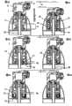
图2a和2b是用于分配流体、液体或糊状产品的装置的部分剖视图,该装置包括如图1所示装在简易瓶上的泵,推动器处于高位置(图2a)和低位置(2b);Figures 2a and 2b are partial sectional views of a device for dispensing fluid, liquid or pasty products comprising a pump mounted on a simple bottle as shown in Figure 1, with the pusher in the high position (Figure 2a) and the low position ( 2b);
图3a和3b是图2所示装置的可选形式的部分剖视图,其中图3a处于高位置而图3b处于低位置的推动器被设计成排出小剂量产品;Figures 3a and 3b are partial cross-sectional views of an alternative form of the device shown in Figure 2, wherein the pusher of Figure 3a in the high position and Figure 3b in the low position is designed to expel small doses of product;
图4a和4b是图2所示装置的另一可选形式的部分剖视图,其中图3a处于高位置而图3b处于低位置的推动器的行进受到轴套的限制;Figures 4a and 4b are partial cross-sectional views of another alternative form of the device shown in Figure 2, wherein the travel of the pusher in the high position of Figure 3a and the low position of Figure 3b is limited by the bushing;
图5是图1所示装置的可选形式的剖视图,它包括汲取管和处于瓶底部的通风口;Figure 5 is a cross-sectional view of an alternative form of the device shown in Figure 1, including a dip tube and a vent at the bottom of the bottle;
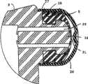
图6是携有密封的封闭帽的推动器的分配鼻端的放大剖视图;以及Figure 6 is an enlarged sectional view of the dispensing nose of the pusher carrying the sealed closure cap; and
图7是图6所示推动器的可选实施例的放大剖视图。FIG. 7 is an enlarged cross-sectional view of an alternative embodiment of the pusher shown in FIG. 6 .
具体实施方式Detailed ways
图1所示的泵1通过帽3装在刚性瓶的主体2上。为实现这一目的,帽3具有圆柱形孔4,泵1的主体5容纳在该孔中,从而能在其中滑动。The pump 1 shown in FIG. 1 is mounted on the
泵1的室6由下阀7(或吸入阀)以及上阀8(或排出阀)限定。两个阀7和8是相同的,但相反安装,这在下面说明。即,根据泵的运动,当排出阀打开时吸入阀关闭,反之亦然。如图1所示,上阀8装在泵的出口喷嘴的末端。The
泵主体的上部部分具有推动器9的形式,允许用户通过克服装在该室外侧的金属螺旋弹簧10向下按压推动器9,这样推动器不接触离开小袋的产品,从而使泵从图1所示的位置启动。在这种运动中,泵的主体在帽3的圆柱形孔4中滑动,直到泵的主体5的下端11靠在与带有下阀7的管13集成在一起的凸缘12上。The upper part of the pump body has the form of a
在推动器9的这种下降运动中,下阀7保持关闭,而上阀8打开,允许室6中的产品离开。During this downward movement of the
当用户释放作用在推动器9的压力时,泵1的主体5在弹簧10的作用下升高,直到环形止动部14接触到形成在帽3中的圆柱形孔4的内壁上的限位部15。When the user releases the pressure on the
在推动器9的这种上升运动中,上阀8保持关闭,而下阀7打开,允许小袋16中的产品进入室6。During this upward movement of the
小袋16通过其颈部17固定在管13的底部,并靠在形成在瓶主体2上的台肩18上。颈部17可以通过超声波焊接固定在管13上。小袋的颈部17的小尺寸,即小于瓶的截面的三分之一,便于通过简单的吹塑技术制造。The pouch 16 is secured by its neck 17 to the bottom of the tube 13 and rests on a shoulder 18 formed on the
由于泵密封并固定在小袋16的颈部17,因此提供了空气入口回路,以便外部空气能进入将小袋与瓶内壁分隔开的空间,从而在该空间中维持足够的压力,使小袋在每次排出产品时能够收缩。空气回路是由主体5的外部部分与圆柱形孔4的内壁之间的空间形成,形成允许空气在泵壁和圆柱形孔之间通过的通道。当推动器启动时该通道打开,当推动器升高时该通道关闭,因为在此升高位置环形肋19紧靠在圆柱形孔4的边缘并且封闭该通道。Since the pump is sealed and secured to the neck 17 of the sachet 16, an air inlet circuit is provided so that outside air can enter the space separating the sachet from the inner wall of the bottle, thereby maintaining sufficient pressure in this space to allow the sachet to be pumped every time. Capable of shrinking when expelling product for the first time. The air circuit is formed by the space between the outer part of the body 5 and the inner wall of the cylindrical hole 4, forming a passage allowing air to pass between the pump wall and the cylindrical hole. The passage is open when the pusher is activated and closed when the pusher is raised, since in this raised position the annular rib 19 abuts against the edge of the cylindrical hole 4 and closes the passage.
用包括根据本发明的泵的图1所示的装置进行的试验已经证明了优异的计量均匀性,以及在糊状物的情况下根据它们的粘度有90到95%的再现性,和在液体情况下有大于95%的再现性。Tests carried out with the device shown in Figure 1 comprising a pump according to the invention have demonstrated excellent metering uniformity, as well as a reproducibility of 90 to 95% in the case of pastes according to their viscosity, and in liquids Cases have greater than 95% reproducibility.
另外,当第一次使用时,仅通过按压推动器三或四次就可以使泵准备好。Additionally, when first used, the pump can be primed by simply depressing the pusher three or four times.
图2表示用于流体,优选的是液体的以密封状态装在简易刚性瓶上的图1所示的泵,其中泵通过汲取管延伸到瓶内。Figure 2 shows the pump shown in Figure 1 mounted in a sealed condition on a simple rigid bottle for a fluid, preferably a liquid, with the pump extending into the bottle through a dip tube.
图2a的泵的推动器处于高位置,位于推动器底部的环形止动部14接触在圆柱形孔内表面上形成限位部15的台肩,该圆柱形孔接收推动器。当用户克服压缩弹簧10下压推动器时,推动器的底部11紧靠形成圆柱形孔4的底部的凸缘12上,如图2b所示。推动器的行程H1表示在图2a中,它等于凸缘12与处于升高位置的推动器的底部11相隔的距离。The pusher of the pump of Fig. 2a is in the high position, the
推动器下降运动导致阀8打开并且处于计量室6内的产品排出,同时吸入阀7在该室中过压的作用下保持关闭。The downward movement of the pusher causes the
当用户随后释放推动器时,在弹簧10的作用下推动器升高,在室6内产生的局部真空导致吸入阀7打开,并且来自瓶的产品经过汲取管20进入,同时上阀8保持关闭。从而使计量室6充满一定剂量的产品,这些产品在用户下一次启动推动器时准备排出去。这些剂量的产品由于上阀8的密封而与外部空气保持隔离。另外,由于上阀8的位置,没有残余的产品与外部气氛接触,从而限制出口孔被材料堆积而阻塞的危险。When the user subsequently releases the pusher, which rises under the action of the
在图3a所示的实施例中,推动器的圆柱形底部延伸超出环形止动部14,推动器底部11与凸缘12底部之间相隔的高度H2较短。活塞的行程限制在高度H2内,以便推动器上的压力仅仅使部分剂量从室6中排出。In the embodiment shown in Figure 3a, the cylindrical bottom of the pusher extends beyond the
图4a表示一个等价的实施例,其中推动器9与图2a的推动器相同,但其行程受设在圆柱形孔底部中、凸缘12底部上的圆环21的限制。推动器行程H3等于图2a的装置的行程H1减去圆环21的高度。Figure 4a shows an equivalent embodiment in which the
图5表示带有本发明的泵1的刚性瓶2,该泵包括两个阀7和8以及推动器9。瓶2补充装有通风系统22。FIG. 5 shows a
通风系统包括塞子23,塞子23插在瓶2底部的孔内,并装有常用类型的过滤器24和阀25。阀设计成,仅当瓶内形成局部真空时,即,当一定剂量产品通过瓶的汲取管20吸入计量室6时,才使外部空气进入瓶中。The ventilation system comprises a
因此,在每次启动泵1的推动器9时空气就被引入瓶2中,以补偿排出剂量的容积,且由于过滤器24不会污染装在瓶内的产品。Thus, air is introduced into the
图6表示上阀8的细节,上阀8带有以密封方式装在推动器9的鼻部的护罩26。通过与弹性材料制成的圆柱形护罩26的底部相互配合的肋27实现密封。并且进一步的密封还通过形成在上阀8的圆柱形底部上的肋28实现。从而护罩26完全罩住阀8,确保设备以密封方式处于关闭状态。FIG. 6 shows a detail of the
如图6所示,产品出口喷嘴包括环绕圆柱形元件30的环形孔29,圆柱形元件30位于阀8前表面中形成的孔31的对面。在关闭位置,阀8的前表面抵在圆柱形元件30上,并且掩盖环形孔29。由于构成阀8的材料的柔性和弹性,环形孔29的管道中的过压造成中心孔31附近的阀的边缘移开,使离开计量室6的产品通过。通过掩盖推动器9的鼻部,密封的护罩26防止外部压力中的任何下降导致相同现象,因此确保安全地存储瓶内所装的产品。As shown in FIG. 6 , the product outlet nozzle comprises an
在图7所示的可选实施例中,沿环形孔29轴线的圆柱形元件30包括在其前表面上与圆柱形元件30同轴的圆柱形突起32。该突起与圆柱形元件的前表面形成台肩,该台肩与阀8中心孔边缘配合,使得圆柱形突起32的前表面处于阀8的表面伸展范围中。In an alternative embodiment shown in FIG. 7 , the
即使阀的边缘不是完美地相对于环形孔29的轴线对称凸出,此实施例也使离开环形孔29的流体流动被引导。This embodiment allows the fluid flow leaving the annular bore 29 to be directed even if the edge of the valve does not project perfectly symmetrically with respect to the axis of the
Claims (12)
Translated fromChineseApplications Claiming Priority (2)
| Application Number | Priority Date | Filing Date | Title |
|---|---|---|---|
| FR0215854AFR2848618B1 (en) | 2002-12-13 | 2002-12-13 | MANUAL ACTUATING PUMP PUMP |
| FR02/15854 | 2002-12-13 |
Publications (2)
| Publication Number | Publication Date |
|---|---|
| CN1726090A CN1726090A (en) | 2006-01-25 |
| CN100464871Ctrue CN100464871C (en) | 2009-03-04 |
Family
ID=32338789
Family Applications (1)
| Application Number | Title | Priority Date | Filing Date |
|---|---|---|---|
| CNB2003801059534AExpired - Fee RelatedCN100464871C (en) | 2002-12-13 | 2003-11-15 | Manual metering pump and device for packaging and dispensing fluid or pasty products |
Country Status (12)
| Country | Link |
|---|---|
| US (1) | US7481336B2 (en) |
| EP (1) | EP1572375B1 (en) |
| JP (1) | JP4358114B2 (en) |
| KR (1) | KR101024348B1 (en) |
| CN (1) | CN100464871C (en) |
| AT (1) | ATE330710T1 (en) |
| AU (1) | AU2003300614A1 (en) |
| CA (1) | CA2507610C (en) |
| DE (1) | DE60306421T2 (en) |
| ES (1) | ES2265608T3 (en) |
| FR (1) | FR2848618B1 (en) |
| WO (1) | WO2004054721A1 (en) |
Families Citing this family (24)
| Publication number | Priority date | Publication date | Assignee | Title |
|---|---|---|---|---|
| US7726521B2 (en)* | 2004-08-17 | 2010-06-01 | Mbhd, Llc | Liquid dispenser |
| US7810677B2 (en)* | 2004-12-04 | 2010-10-12 | Medical Instill Technologies, Inc. | One-way valve and apparatus and method of using the valve |
| FR2889691B1 (en)* | 2005-08-11 | 2010-11-12 | Marc Hemon | DEVICE FOR DISPENSING A FLUID PRODUCT IN THE FORM OF A DROP |
| FR2914294B1 (en)* | 2007-03-29 | 2009-07-10 | Rexam Dispensing Systems Sas | DISTRIBUTION NOZZLE COMPRISING AN AXIS-ATTACHED CLOSURE SLEEVE |
| US20090313845A1 (en)* | 2008-06-23 | 2009-12-24 | Koh Francis H | Portable air blowing device |
| US8618164B2 (en) | 2009-03-31 | 2013-12-31 | Nuvo Research Inc. | Treatment of pain with topical diclofenac compounds |
| CN104816877B (en)* | 2009-07-09 | 2018-02-02 | 恩特格里斯公司 | Liner-based storage system and method of transporting materials |
| ITMI20091648A1 (en)* | 2009-09-25 | 2011-03-26 | Modapack S R L | "GROUP FOR THE PRESSURIZATION AND DISTRIBUTION OF FLUID SUBSTANCES FOR A MANUAL-OPERATED PUMP AND PUMP INCLUDING THE GROUP" |
| EP2643094A4 (en) | 2010-11-23 | 2017-05-24 | Advanced Technology Materials, Inc. | Liner-based dispenser |
| US9211993B2 (en) | 2011-03-01 | 2015-12-15 | Advanced Technology Materials, Inc. | Nested blow molded liner and overpack and methods of making same |
| JP6100752B2 (en)* | 2013-07-25 | 2017-03-22 | 株式会社エイエムジー | Cosmetic container |
| FR3015443B1 (en)* | 2013-12-23 | 2016-07-01 | Lablabo | DEVICE FOR PACKAGING AND DISPENSING FLUID, LIQUID OR PASTY PRODUCTS |
| US9846066B2 (en)* | 2015-07-24 | 2017-12-19 | Silgan Dispensing Systems Corporation | Adjustable dosing dispensers and methods for using the same |
| EP3558844B1 (en) | 2016-12-22 | 2021-10-06 | Unilever IP Holdings B.V. | A shell container suitable for housing a discrete refill container |
| WO2018156599A1 (en)* | 2017-02-22 | 2018-08-30 | Longevity Health Corp. | Medication compliance platforms, systems, and devices |
| FR3063661B1 (en)* | 2017-03-07 | 2021-05-21 | Promens Sa | DEVICE FOR DISTRIBUTION OF A PRODUCT WITH IMPROVED PRIMING |
| US10407293B2 (en)* | 2017-06-08 | 2019-09-10 | United States As Represented By The Secretary Of The Navy | Smart liquid dispenser system |
| EP3890892A1 (en)* | 2018-12-03 | 2021-10-13 | Coty Inc. | Fluid dispenser |
| FR3104554B1 (en) | 2019-12-17 | 2021-12-17 | Linkedtech | Secure enclosure for fluid dispensing metering pump reservoir |
| FR3106054A1 (en) | 2020-01-14 | 2021-07-16 | Linkedtech | AUTOMATIC DISPENSER OF FLUID PRODUCTS CONTAINED IN CARTRIDGES |
| GB202008502D0 (en)* | 2020-06-05 | 2020-07-22 | Alpert Joseph | Environmentally Substainable product dispenser |
| FR3112333B1 (en) | 2020-07-12 | 2023-03-31 | Linkedtech | AUTOMATIC DISPENSER FOR FLUID PRODUCTS CONTAINED IN CARTRIDGES, CARTRIDGE, EJECTION NOZZLE AND METHOD FOR IMPLEMENTING |
| FR3114575B1 (en) | 2020-09-29 | 2022-09-23 | Promens Sa | Dispensing device comprising a non-return valve with a hard point |
| US12207725B1 (en)* | 2023-09-29 | 2025-01-28 | L'oreal | Combination cosmetic dropper and applicator |
Citations (9)
| Publication number | Priority date | Publication date | Assignee | Title |
|---|---|---|---|---|
| US4662544A (en)* | 1985-07-11 | 1987-05-05 | Eagle Manufacturing Company | Apparatus for dispensing fluid |
| EP0538162A1 (en)* | 1991-10-17 | 1993-04-21 | Daniel Crosnier | Sealing means for containers |
| WO1995000195A1 (en)* | 1993-06-18 | 1995-01-05 | Habley Medical Technology Corporation | Medication sprayer |
| EP0733559A1 (en)* | 1995-03-21 | 1996-09-25 | L'oreal | Dispenser for liquid or pasty product, particularly for use in cosmetics |
| EP0747292A1 (en)* | 1994-12-22 | 1996-12-11 | Pentel Kabushiki Kaisha | Discharge container |
| US5926953A (en)* | 1994-04-08 | 1999-07-27 | Sofab | Method of making a pump dispenser using a container with a flexible bag |
| FR2785878A1 (en)* | 1998-11-12 | 2000-05-19 | Jean Philippe Taberlet | Seal assembly for fluid distribution head comprises elastic element shaped as cup with hole that is covered by fixed cylinder and deforms under effect of product distribution pressure. |
| US6354469B1 (en)* | 1997-12-08 | 2002-03-12 | Sivel | Device for packaging and dispensing a product, with manual pump and an air intake filter |
| FR2813863A1 (en)* | 2000-09-08 | 2002-03-15 | Rexam Sofab | LIQUID PRODUCT DISTRIBUTOR |
Family Cites Families (8)
| Publication number | Priority date | Publication date | Assignee | Title |
|---|---|---|---|---|
| DE1254970B (en)* | 1965-07-03 | 1967-11-23 | Erich Pfeiffer K G Metallwaren | Sealing of a membrane pump arranged in a liquid vessel |
| US4723694A (en)* | 1986-09-03 | 1988-02-09 | Marpac Industries, Inc. | Fluid dispensing valve mechanism and assembly |
| FR2679620B1 (en)* | 1991-07-25 | 1993-10-29 | Oreal | ADJUSTABLE VALVE. |
| US5409146A (en)* | 1993-06-03 | 1995-04-25 | Hazard; Robert E. | Dispensing pump with positive shut-off |
| FR2717447B1 (en)* | 1994-03-21 | 1996-05-31 | Labcatal | Dosing device intended to deliver constant unit doses. |
| FR2723618B1 (en)* | 1994-08-11 | 1996-10-31 | Sofab | MEMBRANE PUMP |
| JP3832884B2 (en)* | 1994-12-22 | 2006-10-11 | ぺんてる株式会社 | Discharge container |
| FR2765560B1 (en)* | 1997-07-02 | 1999-08-13 | Oreal | DISPENSER FOR A LIQUID OR PASTY PRODUCT COMPRISING IMPROVED PUMPING MEANS |
- 2002
- 2002-12-13FRFR0215854Apatent/FR2848618B1/ennot_activeExpired - Fee Related
- 2003
- 2003-11-15WOPCT/FR2003/003725patent/WO2004054721A1/enactiveIP Right Grant
- 2003-11-15DEDE60306421Tpatent/DE60306421T2/ennot_activeExpired - Lifetime
- 2003-11-15ESES03813191Tpatent/ES2265608T3/ennot_activeExpired - Lifetime
- 2003-11-15AUAU2003300614Apatent/AU2003300614A1/ennot_activeAbandoned
- 2003-11-15EPEP03813191Apatent/EP1572375B1/ennot_activeExpired - Lifetime
- 2003-11-15CNCNB2003801059534Apatent/CN100464871C/ennot_activeExpired - Fee Related
- 2003-11-15ATAT03813191Tpatent/ATE330710T1/ennot_activeIP Right Cessation
- 2003-11-15JPJP2004559838Apatent/JP4358114B2/ennot_activeExpired - Fee Related
- 2003-11-15USUS10/538,362patent/US7481336B2/ennot_activeExpired - Lifetime
- 2003-11-15CACA2507610Apatent/CA2507610C/ennot_activeExpired - Lifetime
- 2003-11-15KRKR1020057010847Apatent/KR101024348B1/ennot_activeExpired - Fee Related
Patent Citations (9)
| Publication number | Priority date | Publication date | Assignee | Title |
|---|---|---|---|---|
| US4662544A (en)* | 1985-07-11 | 1987-05-05 | Eagle Manufacturing Company | Apparatus for dispensing fluid |
| EP0538162A1 (en)* | 1991-10-17 | 1993-04-21 | Daniel Crosnier | Sealing means for containers |
| WO1995000195A1 (en)* | 1993-06-18 | 1995-01-05 | Habley Medical Technology Corporation | Medication sprayer |
| US5926953A (en)* | 1994-04-08 | 1999-07-27 | Sofab | Method of making a pump dispenser using a container with a flexible bag |
| EP0747292A1 (en)* | 1994-12-22 | 1996-12-11 | Pentel Kabushiki Kaisha | Discharge container |
| EP0733559A1 (en)* | 1995-03-21 | 1996-09-25 | L'oreal | Dispenser for liquid or pasty product, particularly for use in cosmetics |
| US6354469B1 (en)* | 1997-12-08 | 2002-03-12 | Sivel | Device for packaging and dispensing a product, with manual pump and an air intake filter |
| FR2785878A1 (en)* | 1998-11-12 | 2000-05-19 | Jean Philippe Taberlet | Seal assembly for fluid distribution head comprises elastic element shaped as cup with hole that is covered by fixed cylinder and deforms under effect of product distribution pressure. |
| FR2813863A1 (en)* | 2000-09-08 | 2002-03-15 | Rexam Sofab | LIQUID PRODUCT DISTRIBUTOR |
Also Published As
| Publication number | Publication date |
|---|---|
| CA2507610C (en) | 2012-07-24 |
| FR2848618B1 (en) | 2006-06-09 |
| WO2004054721A1 (en) | 2004-07-01 |
| DE60306421D1 (en) | 2006-08-03 |
| CN1726090A (en) | 2006-01-25 |
| EP1572375A1 (en) | 2005-09-14 |
| AU2003300614A1 (en) | 2004-07-09 |
| CA2507610A1 (en) | 2004-07-01 |
| JP2006509624A (en) | 2006-03-23 |
| DE60306421T2 (en) | 2007-02-01 |
| FR2848618A1 (en) | 2004-06-18 |
| KR20050085640A (en) | 2005-08-29 |
| US7481336B2 (en) | 2009-01-27 |
| ES2265608T3 (en) | 2007-02-16 |
| ATE330710T1 (en) | 2006-07-15 |
| EP1572375B1 (en) | 2006-06-21 |
| JP4358114B2 (en) | 2009-11-04 |
| US20060249540A1 (en) | 2006-11-09 |
| KR101024348B1 (en) | 2011-03-23 |
Similar Documents
| Publication | Publication Date | Title |
|---|---|---|
| CN100464871C (en) | Manual metering pump and device for packaging and dispensing fluid or pasty products | |
| JP6215308B2 (en) | Device for packaging / dispensing fluid products with manual pump | |
| US10077150B2 (en) | Dispenser with a reservoir comprising a divider or a porous material | |
| US10315209B2 (en) | Dispenser in particular for liquid to pasty substances | |
| US20120043353A1 (en) | High flow aerosol valve | |
| KR102161238B1 (en) | Foam dispenser | |
| JP2016529169A5 (en) | ||
| KR20140050074A (en) | Portable refillable cream dispenser | |
| US20190077578A1 (en) | Device | |
| US7757900B2 (en) | Dispenser pump | |
| US6902085B2 (en) | Liquid or gel product dispenser forming a metering stick | |
| CN116873392A (en) | Product dispenser and container with the product dispenser | |
| CN100402158C (en) | distribution device | |
| US20030042272A1 (en) | Membrane pump and container equipped therewith | |
| US7178701B2 (en) | Metering pump | |
| EP1991362B1 (en) | Pump for manually dispensing a fluid substance sealed in a container | |
| KR102780668B1 (en) | PP material airless dispenser for cosmetics | |
| KR102413886B1 (en) | Cosmetic vessel having airless pumping type | |
| KR200170002Y1 (en) | Apparatus for vomiting content |
Legal Events
| Date | Code | Title | Description |
|---|---|---|---|
| C06 | Publication | ||
| PB01 | Publication | ||
| C10 | Entry into substantive examination | ||
| SE01 | Entry into force of request for substantive examination | ||
| C14 | Grant of patent or utility model | ||
| GR01 | Patent grant | ||
| CF01 | Termination of patent right due to non-payment of annual fee | ||
| CF01 | Termination of patent right due to non-payment of annual fee | Granted publication date:20090304 |