CN100464795C - fixed dose drug dispensing device - Google Patents
fixed dose drug dispensing deviceDownload PDFInfo
- Publication number
- CN100464795C CN100464795CCNB2004800303776ACN200480030377ACN100464795CCN 100464795 CCN100464795 CCN 100464795CCN B2004800303776 ACNB2004800303776 ACN B2004800303776ACN 200480030377 ACN200480030377 ACN 200480030377ACN 100464795 CCN100464795 CCN 100464795C
- Authority
- CN
- China
- Prior art keywords
- nut
- driver
- follower
- injection
- housing
- Prior art date
- Legal status (The legal status is an assumption and is not a legal conclusion. Google has not performed a legal analysis and makes no representation as to the accuracy of the status listed.)
- Expired - Fee Related
Links
- 239000003814drugSubstances0.000titleclaimsabstractdescription48
- 229940079593drugDrugs0.000titleclaimsdescription34
- 239000012530fluidSubstances0.000claimsabstractdescription10
- 238000002347injectionMethods0.000claimsdescription57
- 239000007924injectionSubstances0.000claimsdescription57
- 238000002360preparation methodMethods0.000claimsdescription14
- 230000013011matingEffects0.000claimsdescription6
- 208000033770Device misuseDiseases0.000claims1
- 210000003811fingerAnatomy0.000description11
- 238000004519manufacturing processMethods0.000description8
- 230000004323axial lengthEffects0.000description5
- 239000004033plasticSubstances0.000description5
- 230000008901benefitEffects0.000description4
- 238000010586diagramMethods0.000description4
- 230000000007visual effectEffects0.000description4
- 230000009471actionEffects0.000description3
- 239000003562lightweight materialSubstances0.000description3
- 230000007246mechanismEffects0.000description3
- 238000000034methodMethods0.000description3
- 239000002991molded plasticSubstances0.000description3
- 230000000712assemblyEffects0.000description2
- 238000000429assemblyMethods0.000description2
- 230000000295complement effectEffects0.000description2
- 239000007788liquidSubstances0.000description2
- 230000001681protective effectEffects0.000description2
- 210000003813thumbAnatomy0.000description2
- 238000011282treatmentMethods0.000description2
- 108010011459ExenatideProteins0.000description1
- 101800004266Glucagon-like peptide 1(7-37)Proteins0.000description1
- 102400000324Glucagon-like peptide 1(7-37)Human genes0.000description1
- 240000007643Phytolacca americanaSpecies0.000description1
- 239000000853adhesiveSubstances0.000description1
- 230000001070adhesive effectEffects0.000description1
- 230000004075alterationEffects0.000description1
- JUFFVKRROAPVBI-PVOYSMBESA-Nchembl1210015Chemical compoundC([C@@H](C(=O)N[C@@H]([C@@H](C)CC)C(=O)N[C@@H](CCC(O)=O)C(=O)N[C@@H](CC=1C2=CC=CC=C2NC=1)C(=O)N[C@@H](CC(C)C)C(=O)N[C@@H](CCCCN)C(=O)N[C@@H](CC(=O)N[C@H]1[C@@H]([C@@H](O)[C@H](O[C@H]2[C@@H]([C@@H](O)[C@@H](O)[C@@H](CO[C@]3(O[C@@H](C[C@H](O)[C@H](O)CO)[C@H](NC(C)=O)[C@@H](O)C3)C(O)=O)O2)O)[C@@H](CO)O1)NC(C)=O)C(=O)NCC(=O)NCC(=O)N1[C@@H](CCC1)C(=O)N[C@@H](CO)C(=O)N[C@@H](CO)C(=O)NCC(=O)N[C@@H](C)C(=O)N1[C@@H](CCC1)C(=O)N1[C@@H](CCC1)C(=O)N1[C@@H](CCC1)C(=O)N[C@@H](CO)C(N)=O)NC(=O)[C@H](CC(C)C)NC(=O)[C@H](CCCNC(N)=N)NC(=O)[C@@H](NC(=O)[C@H](C)NC(=O)[C@H](CCC(O)=O)NC(=O)[C@H](CCC(O)=O)NC(=O)[C@H](CCC(O)=O)NC(=O)[C@H](CCSC)NC(=O)[C@H](CCC(N)=O)NC(=O)[C@H](CCCCN)NC(=O)[C@H](CO)NC(=O)[C@H](CC(C)C)NC(=O)[C@H](CC(O)=O)NC(=O)[C@H](CO)NC(=O)[C@@H](NC(=O)[C@H](CC=1C=CC=CC=1)NC(=O)[C@@H](NC(=O)CNC(=O)[C@H](CCC(O)=O)NC(=O)CNC(=O)[C@@H](N)CC=1NC=NC=1)[C@@H](C)O)[C@@H](C)O)C(C)C)C1=CC=CC=C1JUFFVKRROAPVBI-PVOYSMBESA-N0.000description1
- 238000007906compressionMethods0.000description1
- 230000006835compressionEffects0.000description1
- 238000010276constructionMethods0.000description1
- 230000007812deficiencyEffects0.000description1
- 206010012601diabetes mellitusDiseases0.000description1
- 229960001519exenatideDrugs0.000description1
- 210000005224forefingerAnatomy0.000description1
- 239000007972injectable compositionSubstances0.000description1
- 238000003780insertionMethods0.000description1
- 230000037431insertionEffects0.000description1
- 238000009434installationMethods0.000description1
- 238000002483medicationMethods0.000description1
- 230000000149penetrating effectEffects0.000description1
- 230000002093peripheral effectEffects0.000description1
- GCYXWQUSHADNBF-AAEALURTSA-Npreproglucagon 78-108Chemical compoundC([C@@H](C(=O)N[C@@H]([C@@H](C)CC)C(=O)N[C@@H](C)C(=O)N[C@@H](CC=1C2=CC=CC=C2NC=1)C(=O)N[C@@H](CC(C)C)C(=O)N[C@@H](C(C)C)C(=O)N[C@@H](CCCCN)C(=O)NCC(=O)N[C@@H](CCCNC(N)=N)C(=O)NCC(O)=O)NC(=O)[C@H](CCC(O)=O)NC(=O)[C@H](CCCCN)NC(=O)[C@H](C)NC(=O)[C@H](C)NC(=O)[C@H](CCC(N)=O)NC(=O)CNC(=O)[C@H](CCC(O)=O)NC(=O)[C@H](CC(C)C)NC(=O)[C@H](CC=1C=CC(O)=CC=1)NC(=O)[C@H](CO)NC(=O)[C@H](CO)NC(=O)[C@@H](NC(=O)[C@H](CC(O)=O)NC(=O)[C@H](CO)NC(=O)[C@@H](NC(=O)[C@H](CC=1C=CC=CC=1)NC(=O)[C@@H](NC(=O)CNC(=O)[C@H](CCC(O)=O)NC(=O)[C@H](C)NC(=O)[C@@H](N)CC=1N=CNC=1)[C@@H](C)O)[C@@H](C)O)C(C)C)C1=CC=CC=C1GCYXWQUSHADNBF-AAEALURTSA-N0.000description1
- 230000008569processEffects0.000description1
- 238000009420retrofittingMethods0.000description1
- 239000007787solidSubstances0.000description1
- 238000009423ventilationMethods0.000description1
- 238000003466weldingMethods0.000description1
Images


Classifications
- A—HUMAN NECESSITIES
- A61—MEDICAL OR VETERINARY SCIENCE; HYGIENE
- A61M—DEVICES FOR INTRODUCING MEDIA INTO, OR ONTO, THE BODY; DEVICES FOR TRANSDUCING BODY MEDIA OR FOR TAKING MEDIA FROM THE BODY; DEVICES FOR PRODUCING OR ENDING SLEEP OR STUPOR
- A61M5/00—Devices for bringing media into the body in a subcutaneous, intra-vascular or intramuscular way; Accessories therefor, e.g. filling or cleaning devices, arm-rests
- A61M5/178—Syringes
- A61M5/31—Details
- A61M5/315—Pistons; Piston-rods; Guiding, blocking or restricting the movement of the rod or piston; Appliances on the rod for facilitating dosing ; Dosing mechanisms
- A61M5/31565—Administration mechanisms, i.e. constructional features, modes of administering a dose
- A61M5/31576—Constructional features or modes of drive mechanisms for piston rods
- A61M5/31578—Constructional features or modes of drive mechanisms for piston rods based on axial translation, i.e. components directly operatively associated and axially moved with plunger rod
- A61M5/3158—Constructional features or modes of drive mechanisms for piston rods based on axial translation, i.e. components directly operatively associated and axially moved with plunger rod performed by axially moving actuator operated by user, e.g. an injection button
- A—HUMAN NECESSITIES
- A61—MEDICAL OR VETERINARY SCIENCE; HYGIENE
- A61M—DEVICES FOR INTRODUCING MEDIA INTO, OR ONTO, THE BODY; DEVICES FOR TRANSDUCING BODY MEDIA OR FOR TAKING MEDIA FROM THE BODY; DEVICES FOR PRODUCING OR ENDING SLEEP OR STUPOR
- A61M5/00—Devices for bringing media into the body in a subcutaneous, intra-vascular or intramuscular way; Accessories therefor, e.g. filling or cleaning devices, arm-rests
- A61M5/178—Syringes
- A61M5/31—Details
- A61M5/315—Pistons; Piston-rods; Guiding, blocking or restricting the movement of the rod or piston; Appliances on the rod for facilitating dosing ; Dosing mechanisms
- A61M5/31533—Dosing mechanisms, i.e. setting a dose
- A61M5/31535—Means improving security or handling thereof, e.g. blocking means, means preventing insufficient dosing, means allowing correction of overset dose
- A61M5/31541—Means preventing setting of a dose beyond the amount remaining in the cartridge
- A—HUMAN NECESSITIES
- A61—MEDICAL OR VETERINARY SCIENCE; HYGIENE
- A61M—DEVICES FOR INTRODUCING MEDIA INTO, OR ONTO, THE BODY; DEVICES FOR TRANSDUCING BODY MEDIA OR FOR TAKING MEDIA FROM THE BODY; DEVICES FOR PRODUCING OR ENDING SLEEP OR STUPOR
- A61M5/00—Devices for bringing media into the body in a subcutaneous, intra-vascular or intramuscular way; Accessories therefor, e.g. filling or cleaning devices, arm-rests
- A61M5/178—Syringes
- A61M5/31—Details
- A61M5/315—Pistons; Piston-rods; Guiding, blocking or restricting the movement of the rod or piston; Appliances on the rod for facilitating dosing ; Dosing mechanisms
- A61M5/31533—Dosing mechanisms, i.e. setting a dose
- A61M5/31545—Setting modes for dosing
- A61M5/31548—Mechanically operated dose setting member
- A61M5/3155—Mechanically operated dose setting member by rotational movement of dose setting member, e.g. during setting or filling of a syringe
- A—HUMAN NECESSITIES
- A61—MEDICAL OR VETERINARY SCIENCE; HYGIENE
- A61M—DEVICES FOR INTRODUCING MEDIA INTO, OR ONTO, THE BODY; DEVICES FOR TRANSDUCING BODY MEDIA OR FOR TAKING MEDIA FROM THE BODY; DEVICES FOR PRODUCING OR ENDING SLEEP OR STUPOR
- A61M5/00—Devices for bringing media into the body in a subcutaneous, intra-vascular or intramuscular way; Accessories therefor, e.g. filling or cleaning devices, arm-rests
- A61M5/178—Syringes
- A61M5/31—Details
- A61M2005/3125—Details specific display means, e.g. to indicate dose setting
- A—HUMAN NECESSITIES
- A61—MEDICAL OR VETERINARY SCIENCE; HYGIENE
- A61M—DEVICES FOR INTRODUCING MEDIA INTO, OR ONTO, THE BODY; DEVICES FOR TRANSDUCING BODY MEDIA OR FOR TAKING MEDIA FROM THE BODY; DEVICES FOR PRODUCING OR ENDING SLEEP OR STUPOR
- A61M2205/00—General characteristics of the apparatus
- A61M2205/58—Means for facilitating use, e.g. by people with impaired vision
- A61M2205/581—Means for facilitating use, e.g. by people with impaired vision by audible feedback
- A—HUMAN NECESSITIES
- A61—MEDICAL OR VETERINARY SCIENCE; HYGIENE
- A61M—DEVICES FOR INTRODUCING MEDIA INTO, OR ONTO, THE BODY; DEVICES FOR TRANSDUCING BODY MEDIA OR FOR TAKING MEDIA FROM THE BODY; DEVICES FOR PRODUCING OR ENDING SLEEP OR STUPOR
- A61M2205/00—General characteristics of the apparatus
- A61M2205/58—Means for facilitating use, e.g. by people with impaired vision
- A61M2205/583—Means for facilitating use, e.g. by people with impaired vision by visual feedback
- A61M2205/585—Means for facilitating use, e.g. by people with impaired vision by visual feedback having magnification means, e.g. magnifying glasses
- A—HUMAN NECESSITIES
- A61—MEDICAL OR VETERINARY SCIENCE; HYGIENE
- A61M—DEVICES FOR INTRODUCING MEDIA INTO, OR ONTO, THE BODY; DEVICES FOR TRANSDUCING BODY MEDIA OR FOR TAKING MEDIA FROM THE BODY; DEVICES FOR PRODUCING OR ENDING SLEEP OR STUPOR
- A61M5/00—Devices for bringing media into the body in a subcutaneous, intra-vascular or intramuscular way; Accessories therefor, e.g. filling or cleaning devices, arm-rests
- A61M5/178—Syringes
- A61M5/24—Ampoule syringes, i.e. syringes with needle for use in combination with replaceable ampoules or carpules, e.g. automatic
- A—HUMAN NECESSITIES
- A61—MEDICAL OR VETERINARY SCIENCE; HYGIENE
- A61M—DEVICES FOR INTRODUCING MEDIA INTO, OR ONTO, THE BODY; DEVICES FOR TRANSDUCING BODY MEDIA OR FOR TAKING MEDIA FROM THE BODY; DEVICES FOR PRODUCING OR ENDING SLEEP OR STUPOR
- A61M5/00—Devices for bringing media into the body in a subcutaneous, intra-vascular or intramuscular way; Accessories therefor, e.g. filling or cleaning devices, arm-rests
- A61M5/178—Syringes
- A61M5/31—Details
- A61M5/315—Pistons; Piston-rods; Guiding, blocking or restricting the movement of the rod or piston; Appliances on the rod for facilitating dosing ; Dosing mechanisms
- A61M5/31533—Dosing mechanisms, i.e. setting a dose
- A61M5/31545—Setting modes for dosing
- A61M5/31548—Mechanically operated dose setting member
- A61M5/3155—Mechanically operated dose setting member by rotational movement of dose setting member, e.g. during setting or filling of a syringe
- A61M5/31551—Mechanically operated dose setting member by rotational movement of dose setting member, e.g. during setting or filling of a syringe including axial movement of dose setting member
Landscapes
- Health & Medical Sciences (AREA)
- Vascular Medicine (AREA)
- Engineering & Computer Science (AREA)
- Anesthesiology (AREA)
- Biomedical Technology (AREA)
- Heart & Thoracic Surgery (AREA)
- Hematology (AREA)
- Life Sciences & Earth Sciences (AREA)
- Animal Behavior & Ethology (AREA)
- General Health & Medical Sciences (AREA)
- Public Health (AREA)
- Veterinary Medicine (AREA)
- Infusion, Injection, And Reservoir Apparatuses (AREA)
- Acyclic And Carbocyclic Compounds In Medicinal Compositions (AREA)
- Medical Preparation Storing Or Oral Administration Devices (AREA)
Abstract
Description
Translated fromChinese技术背景technical background
本发明涉及药物分配装置,特别涉及一种易于分配固定剂量液体药物的装置。The present invention relates to medicament dispensing devices, and more particularly to a device which facilitates the dispensing of fixed doses of liquid medicaments.
背景技术Background technique
患有多种不同疾病的患者通常需要自己进行药物注射。为了使患者能够方便准确地自己给药,已经开发了统称为注射器笔或者注射笔的多种装置。一般地,这些笔装有筒体,所述筒体包括活塞并且装有多次剂量液体药物。一个驱动元件从注射笔的底部延伸并且可操作地与在笔中的通常更靠后的用于控制驱动元件动作的机构相连,驱动元件向前移动以推动筒中的活塞,使得所包含的药物从在相对的筒端的出口通常通过穿透在相对端部处的塞的针被分配。在一次性使用或者预充填的针中,在针已用过并且消耗筒内的药物后,使用者抛弃整个笔,接着使用新的替代笔。在可重复使用的笔中,在针已用过并且消耗筒内的药物后,该笔被拆开以利用新的筒代替用过的筒,接着重新组装该笔以使其能够继续使用。Patients with many different medical conditions often need to administer their own medication injections. In order to allow patients to self-administer medications conveniently and accurately, a variety of devices collectively referred to as syringe pens or injection pens have been developed. Typically, these pens contain a barrel that includes a piston and holds multiple doses of liquid medication. A drive element extends from the bottom of the pen and is operatively connected to a mechanism in the pen, usually further rearward, for controlling the action of the drive element, which moves forward to push a piston in the barrel so that the contained drug is released from the The outlet at the opposite barrel end is typically dispensed by a needle penetrating a bung at the opposite end. In single-use or prefilled needles, after the needle has been used and the contents of the cartridge are consumed, the user discards the entire pen and uses a new replacement pen. In a reusable pen, after the needle has been used and the drug in the cartridge is consumed, the pen is disassembled to replace the spent cartridge with a new cartridge, and then the pen is reassembled to enable continued use.
一种已知的用于分配固定剂量的药物的注射笔被披露在PCT公开号WO 02/30495中。尽管这种注射笔以及本领域已知的其他装置可能适于输送固定剂量,但希望提供一种操作更简单并且适当输送固定剂量的药物。One known injection pen for dispensing fixed doses of medication is disclosed in PCT Publication No. WO 02/30495. While such injection pens, as well as other devices known in the art, may be suitable for delivering fixed doses, it would be desirable to provide a drug that is easier to handle and properly delivers fixed doses.
发明内容Contents of the invention
在其一种形式中,本发明提供一种药物分配设备,所述药物分配设备包括:壳体;轴向延伸的驱动元件,在剂量准备期间驱动元件可转动和轴向地固定在壳体内,在剂量注射期间驱动元件可转动地固定并且在相对于壳体的远端方向上轴向移动,驱动元件包括带螺纹的轴;限定药物充填腔的流体容器,所述药物充填腔的一端具有可移动的活塞,另一端具有出口,所述活塞可与驱动元件接合以便当驱动元件向远端移动时使得活塞朝向出口移动;与驱动元件轴螺纹接合的螺母,在螺母相对于驱动元件转动过程中螺母可相对于驱动元件轴轴向移动;以及可相对于壳体转动和轴向移动的螺母驱动器。螺母和驱动器包括配合元件,当所述配合元件转动接合时它们将螺母和驱动器锁定在一起,当配合元件脱开时它们可使得螺母和驱动器相对转动。所述设备还包括设置在驱动器和壳体中的一个上的引导件以及设置在驱动器和壳体中的另一个上的从动件,其中所述引导件和从动件相互配合以便于使用者沿着操作该设备的移动路径使得驱动器相对于壳体移动,所述移动路径包括剂量准备部分和剂量注射部分,所述剂量准备部分包括按顺序的复位部分、螺母接合部分和的螺母转动部分,注射部分将螺母转动部分和复位部分连接在一起。当驱动器被设置在复位部分时,螺母和驱动器的配合元件脱开,并且当驱动器从复位部分通过螺母接合部分移动到螺母转动部分时螺母和驱动器的配合元件接合。当驱动器从螺母接合部分通过螺母转动部分移动到注射部分时螺母和驱动器的配合元件的接合使得螺母沿着螺纹轴向近端旋动。当驱动器从螺母转动部分通过注射部分移动到复位部分时,螺母和驱动元件在远端方向移动以使得流体容器活塞轴向前进从出口分配药物,并且螺母和驱动器的配合元件脱开。引导件包括硬止档,硬止档使得从动件限定驱动器移动路径的复位部分的一端,当硬止档与从动件抵靠时硬止档转动地使得驱动器与移动路径的螺母接合部分对准。In one of its forms, the invention provides a medicament dispensing device comprising: a housing; an axially extending drive element rotatably and axially fixed within the housing during dose preparation, A drive element is rotatably fixed and axially movable in a distal direction relative to the housing during dose injection, the drive element comprising a threaded shaft; a fluid container defining a drug filling cavity having a a moving piston, having an outlet at the other end, engageable with the drive element to move the piston toward the outlet as the drive element moves distally; a nut threadedly engaged with the drive element shaft, during rotation of the nut relative to the drive element a nut axially movable relative to the drive element shaft; and a nut driver rotatable and axially movable relative to the housing. The nut and driver include cooperating elements which lock the nut and driver together when rotationally engaged and which permit relative rotation of the nut and driver when disengaged. The device also includes a guide provided on one of the driver and the housing and a follower provided on the other of the driver and the housing, wherein the guide and the follower cooperate to facilitate user moving the driver relative to the housing along a movement path for operating the device comprising a dose preparation portion and a dose injection portion, the dose preparation portion comprising in sequence a reset portion, a nut engagement portion and a nut turning portion, The injection part connects the nut turning part and the reset part together. When the driver is set in the reset portion, the nut and the driver's mating element are disengaged, and the nut and the driver's mating element engage when the driver moves from the reset portion through the nut engaging portion to the nut turning portion. Engagement of the cooperating elements of the nut and driver causes the nut to rotate proximally along the threaded axis as the driver moves from the nut engaging portion through the nut turning portion to the injection portion. As the driver moves from the nut turning portion through the injection portion to the reset portion, the nut and drive element move in the distal direction such that the fluid container piston is advanced axially to dispense medication from the outlet and the nut and driver mating elements are disengaged. The guide includes a hard stop such that the follower defines one end of the return portion of the drive path of travel, the hard stop rotationally aligns the driver with the nut engaging portion of the travel path when the hard stop abuts the follower. allow.
本发明的一个优点是,可提供一种操作简单并且在每一次使用时能够适当地输送相同的预定剂量的药物的药物分配设备。It is an advantage of the present invention that a medicament dispensing device is provided which is simple to operate and properly delivers the same predetermined dose of medicament on each use.
本发明的另一个优点是,可提供一种包括防止笔的某些不适当操作的元件的药物分配设备。Another advantage of the present invention is that it is possible to provide a medicament dispensing device comprising elements preventing certain improper operation of the pen.
本发明的另一个优点是,可提供一种通过制备和输送一定剂量的药物所需的步骤循环有助于程序化的药物分配设备。Another advantage of the present invention is that it provides a drug dispensing device that facilitates programming through the cycle of steps required to prepare and deliver a dose of drug.
附图说明Description of drawings
参照下面结合附图对本发明的实施例的描述可以明显地看出本发明的上述和其他优点和目的以及得到它们的方式,并且可更好地理解本发明本身,在附图中:The above-mentioned and other advantages and objectives of the present invention and the manner in which they are obtained can be clearly seen with reference to the description of the embodiments of the present invention below in conjunction with the accompanying drawings, and the present invention itself can be better understood. In the accompanying drawings:
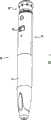
图1是本发明所涉及的药物分配设备的一个实施例的透视图;Figure 1 is a perspective view of one embodiment of a drug dispensing device according to the present invention;
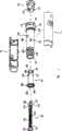
图2是图1的设备的一些部分的分解透视图;Figure 2 is an exploded perspective view of some portions of the device of Figure 1;
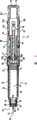
图3是图1的设备的纵向截面图,其中所示的设备没有帽并且在其远端连接有笔针组件;Fig. 3 is a longitudinal cross-sectional view of the device of Fig. 1, wherein the device is shown without a cap and with a pen needle assembly attached at its distal end;
图4是图2的螺母驱动器的局剖前视图以露出多个内键;Figure 4 is a partial cutaway front view of the nut driver of Figure 2 to expose a plurality of internal keys;
图5是图1的设备的两部分壳体的前视图,其中一个壳体部分已经转动打开180度以露出壳体部分的内凹槽;Figure 5 is a front view of the two-part housing of the apparatus of Figure 1, one of the housing parts having been rotated open 180 degrees to expose the inner recess of the housing part;
图6是壳体和螺母驱动器的局部剖视的部分透视图,特别示出了在到达调零位置之前的单元棘爪指;Figure 6 is a partially cutaway partial perspective view of the housing and nut driver, particularly showing the detent fingers of the unit prior to reaching the zero position;
图7是图1的设备的引导件和从动件的部分的两维示意图,其中所示的设备在剂量准备的初始阶段被布置并且在先前注射后立即被步骤;Figure 7 is a two-dimensional schematic illustration of parts of the guide and follower of the device of Figure 1, wherein the device shown is arranged at the initial stage of dose preparation and is stepped immediately after a previous injection;
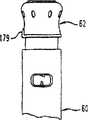
图7a是当如图7中所示的布置时的设备的近端的前视图;Figure 7a is a front view of the proximal end of the device when arranged as shown in Figure 7;
图8是与图7类似的概念性的两维示意图,但其中所示的设备在角度复位完成后并且在该设备在其操作的螺母接合阶段中被操控之前被布置;Fig. 8 is a conceptual two-dimensional schematic diagram similar to Fig. 7, but wherein the device shown is deployed after angular resetting is complete and before the device is manipulated in the nut engagement phase of its operation;
图8a是当如图8中所示的布置时的设备的近端的前视图;Figure 8a is a front view of the proximal end of the device when arranged as shown in Figure 8;
图9是与图7类似的概念性的两维示意图,但其中所示的设备在螺母接合阶段完成后并且在该设备在其操作的螺母转动阶段中被操控之前被布置;Fig. 9 is a conceptual two-dimensional schematic diagram similar to Fig. 7, but wherein the device shown is arranged after the nut engaging phase is completed and before the device is manipulated in the nut turning phase of its operation;
图9a是当如图9中所示的布置时的设备的近端的前视图;Figure 9a is a front view of the proximal end of the device when arranged as shown in Figure 9;
图10是与图7类似的概念性的两维示意图,但其中所示的设备在螺母转动阶段完成后并且在该设备在其操作的注射阶段中被操控之前被布置;Figure 10 is a conceptual two-dimensional schematic diagram similar to Figure 7, but wherein the device shown is arranged after the nut turning phase is completed and before the device is manipulated in the injection phase of its operation;
图10a是当如图10中所示的布置时的设备的近端的前视图;Figure 10a is a front view of the proximal end of the device when arranged as shown in Figure 10;
图11是与图7类似的概念性的两维示意图,但其中所示的设备在其操作的注射阶段被布置;Figure 11 is a conceptual two-dimensional schematic diagram similar to Figure 7, but with the device shown arranged during the injection phase of its operation;
图11a是当如图11中所示的布置时的设备的近端的前视图;以及Figure 11a is a front view of the proximal end of the device when arranged as shown in Figure 11; and
图12是图2的螺母的透视远端视图。12 is a perspective distal view of the nut of FIG. 2 .
在附图中,相应的附图标记表示相应的部件。尽管附图示出了本发明的一个实施例,附图不是一定成比例的,在一些图中某些特征可被夸大或者省略以更好地示出和说明本发明。Corresponding reference numerals indicate corresponding parts throughout the drawings. Although the drawings illustrate one embodiment of the invention, the drawings are not necessarily to scale and in some figures certain features may be exaggerated or omitted to better illustrate and explain the invention.
具体实施方式Detailed ways
现参见图1-3,其中示出了本发明的药物分配设备的第一实施例。参照图1或者其他任何一个附图,在该详细描述中的任何方向性参照,诸如右或者左,是为了便于说明,其本身未将本发明或者其任何一个部件限制在任何特定位置或者空间取向。Referring now to Figures 1-3, there is shown a first embodiment of the medication dispensing device of the present invention. 1 or any other figure, any directional references in this detailed description, such as right or left, are for ease of illustration and do not in themselves limit the invention or any of its components to any particular position or orientation in space .
所示设备20为注射器笔,该笔具有细长的类似于书写用具的形状,但其他形状也在本发明的范围内。注射器笔20的许多方面概念上与在美国专利US 5938642、US 6001089和6221046以及PCT公开号为WO02/30495中披露的装置类似,这些文献的所有内容在这里合并参考以便于本发明的理解。The illustrated
药物注射器笔20是一种一次性使用或者预充填的笔,即,在装在其中的药物量被笔的多次操作而被耗尽后,整个笔被抛弃而不是被重新利用并且重新安装代替的药物容器。笔20被使用者操作以注射预定剂量的药物,诸如与制造者装在其中的一些治疗方法相适应。例如,用于治疗糖尿病的包含类似胰高血糖素的缩氨酸-1(7-37)(包括其类似物和衍生物)以及exendin-4及其类似物和衍生物的可注射配方可适用于本发明的设备。The
注射器笔20一般包括远端部分22和近端部分24。远端部分22包含药物流体以在笔操作后使其在远端排出,在图1中,所示的该部分被接收在笔帽21内。近端部分24包含用于从针端压迫所包含的药物的注射机构。
远端部分22包括护套30,筒40固定在护套30中。所示的筒护套30是由透明塑料形成的一体结构以使得筒的内容物是可见的。护套30包括管部32和逐步减小的颈部34。环状端面36形成部分34的远端。管部32包括尺寸适于容纳筒的内中空部分。管部32的外部靠近其近端形成有棘爪,诸如与笔帽构造配合以使得笔帽21以可拆卸的方式咬合安装在护套30上的周肋33。The
筒40采用常规设计并且限定了充填药物的腔42,充填药物的腔42在其近端处被活塞44封闭,活塞44轴向滑动和密封地与筒内壁接合以将流体药物装在腔42内。筒腔42的远出口端被由帽48固定的隔膜46密封,帽48被固定在筒的逐步减小的颈部49。
如图3中所示,已知设计的笔尖组件50被安装在设备20上并且包括一端具有远端尖部54和另一端具有近点56的双端针套管或者注射针52。注射针52安装在管状毂58,管状毂58诸如通过内螺纹与颈部34上的外螺纹配合以便以可拆卸的方式安装在护套远端。安装在毂部上的未示出的针帽可保护尖54,当笔20用于注射药物时针帽被去除。尽管所示的针组件具有一个注射针,但可与笔20结合使用的针组件可采用本领域已知的各种类型,包括,但不限于,具有一个或者多个缩短的注射针的组件,包括微型针组。As shown in FIG. 3 , a
如图3中所示,当笔针组件50安装在护套30上时,注射针52的近点56通过在环形端面36中的中心开口,并且穿透筒隔膜46以提供流体流出口,在注射器笔20的操作过程中筒腔42内的药物可通过所述流体流出口从针尖54分配。As shown in FIG. 3, when the
在使用体积比所示的小的筒的实施例中,诸如具有类似的总长度的较小直径的筒,管32的内部可形成有多个以一定角度间隔的、径向向内凸出的肋,诸如沿着管的长度纵向延伸的以90度隔开的四个肋,使得较小直径的筒在其中定中心。这样的肋还以径向较短的形式出现在容纳上述筒40的管部以允许护套30的通风开口。In embodiments using a smaller volume than shown, such as a smaller diameter barrel having a similar overall length, the interior of
图1-3中所示和上述的流体药物容器是示意性的并且不被限制为可在本发明的保护范围内使用的其他结构。例如,不使用其中独特的筒被装在一体护套内的所示容器,筒可被构造得足够耐用并且适于直接固定在笔近端部分24,并且在其周围没有任何保护性护套,并且笔针组件可直接安装在筒上。The fluid drug containers shown in Figures 1-3 and described above are schematic and are not limited to other configurations that may be used within the scope of the present invention. For example, instead of using the illustrated container in which the unique barrel is housed within an integral sheath, the barrel can be constructed sufficiently durable and adapted to be secured directly to the pen
注射器笔20的近端部分24包括外保护性壳体60、螺母驱动器62、螺母64和螺钉元件66。参见图5,所示壳体60的两个部分由重量轻的材料(诸如注射模制塑料)制成。所示壳体部分为纵向半壳70和71,在制造过程中利用一种已知的方式(诸如超声波焊接)将它们固定在一起。例如,部分70的凸出焊缝73a插入部分71的凹入焊缝73b内。容纳部分71上的销75的在壳体部分70中的一对凹槽74以及安装在壳体部分边缘上的互补凹槽中的几个肋用于在制造组件过程中使得半壳对齐。壳体部分70和71在组装时形成限定内中空部分76的壳体,螺钉元件66在内中空部分76中沿着轴向或者纵向延伸。在壳体部分71中的窗78被示出。窗78使得位于螺母驱动器62的外表面上的视觉记号变得可见,所述视觉记号有助于笔操作,如下面进一步描述的。如果需要的话,窗78可设有放大透镜以使得螺母驱动器上的记号变得更可见。The
半壳70和71的远端减小以分别形成环部82和84,环部82和84的尺寸适于将护套30的径向放大的套部38接收在其上。在制造商组装笔的过程中,套部38以一种已知的方式(诸如通过还用于固定半壳70和71的紫外线硬化粘接剂)固定地安装或者紧固在环部82、84上。在该护套安装过程中,使得筒40轴向地直接限制在护套环形表面36的内表面和壳体的部分之间。在所示实施例中,这样的限制壳体部分是与壳体部分70的横向延伸的环形肩部90整体形成的并且从其远端地轴向凸出的肋88以及在壳体部分71的类似的肩部94上的类似肋92。当壳体部分被组装时肋88和92以大约180度取向隔开以抵靠筒的径向相对的端部。The distal ends of half-
径向向内凸出的凸缘96与肩部90整体形成,一个或者多个(诸如一对)弹性棘爪或者凸起98从凸缘96远端凸出。凸起98和凸缘96用于防止螺钉元件66相对于壳体60轴向近端移动(即,倒退)和转动。肩部94类似地包括凸缘100和凸起102。在每一个壳体部分上的凸起轴向交错以接合下面描述的连续棘齿。在笔使用过程中(诸如在剂量准备或者剂量注射过程中)防倒退特征防止螺钉元件66近端移动。在本发明的保护范围内,其他类型的防倒退和防转动机构可使用。A radially inwardly projecting flange 96 is integrally formed with
肩部90和94的近表面都包括包括三个直立的斜坡类型的一组肋104。肋104相互配合地设有螺母64以当螺母未转动地与驱动器62锁定时防止无意的螺母转动。The proximal surfaces of
分别在部分70和71上的横向肋106和108有助于螺母驱动器62在壳体内定心。关于制造和组装的壳体的其他所示方面包括:向内凸出的台阶105,当在制造过程中壳体部分从它们的模型被压迫时所述台阶105接收喷射销;在壳体部分组装在一起的过程中使用的开口107;图3中所示的作为在制造过程中在塑料被注射到模型的情况下的门槽的凹部109;以及与肋122整体形成并且提供足够厚的塑料区域以进入的耳111。Transverse ribs 106 and 108 on
壳体部分70还包括形成在其中的U形沟槽以限定在其端部具有向内延伸的指状物112的挠性支腿110。指状物112包括终止于平部116中的近端的锥形或者倾斜表面114,平部116具有横向的远端表面118。
参见图5以及图7-11,壳体60的近端区域包括在其内表面上的引导特征,所述引导特征与在螺纹驱动器62的外表面上的从动件配合以有助于或者促使驱动器以及笔20的适当操作。引导件120包括周向延伸的径向向内凸出的肋122,肋122包括第一部分124、第二部分126、第三部分128和第四部分130。第一部分124是直的并且为纵向取向。第二部分126具有从第一部分124的近端124b延伸的第一端126e。第二部分126相对于笔纵轴倾斜以呈螺旋取向并且从端部126e沿着其长度近端地略微持续。第四部分130位于第二部分126的远端,并且具有终止于第一部分124的远端124a的端部130b。当第二部分126从第一部分124延伸时,第四部分130沿着相反的有角度的方向从第一部分124延伸,并且第四部分130是直的并且其取向一般横穿笔20的轴线。第三部分128是直的并且纵向取向,其轴向长度比第一部分124长,并且其具有终止于第二部分126的端部126b的近端128a和终止于第四部分130的端部130a的远端128b以直接连接引导肋部分126和130。在130的端部处的略微偏角调节131用作限制从动件戳坏和有助于远端压迫螺母和螺钉的导入部分。在组装过程中所述部分略微未对准的情况下,第二部分126和第四部分130都包括在壳体部分71和壳体部分72的相交部分处的小斜面以消除从动件戳坏。Referring to Figures 5 and 7-11, the proximal region of
引导件120还包括特别进一步促进适当的笔操作和用作有效或者自然止档的径向向内凸出的元件132以解决某些可能的笔的使用不当的模式。尽管所示的是一个实心模制的元件,引导件可具有不同的结构,诸如较薄的多角度的肋。The guide 120 also includes a radially inwardly projecting
引导件132包括直的第一表面134、倾斜的第二表面136以及直的第三表面138。由于从动件的轴向长度,在第一表面134与肋部124的右表面之间限定通道140以引导从动件移动。引导件第二表面136是肋部126的面对表面的远端并且与之平行,并且与这样的面对表面一起在它们之间限定通道142.由于从动件的轴向长度,在第三表面138与肋部128的左表面之间限定通道144以引导从动件移动。引导件表面134和138是纵向布置的,因此相互平行以及与肋部表面平行,并且与它们一起形成通道。The
从动件150从螺母驱动器62的外表面152径向向外凸出以与引导件120相互作用。所示的从动件150整体形状为矩形,具有平面154、156、158和160。从动件150和引导件120的尺寸和形状相互配合以适于装配,从而限制它们之间的不希望的间隙和移动同时不防止相对滑动。在笔使用过程中(诸如在剂量准备或者剂量注射过程中)从动件150不径向收缩。尽管肋部和引导件120的表面是不中断和连续的,但应该理解的是,对于从动件控制,这样的方面可是连续的,即使其中具有小的中断,只要这样的中断不允许不希望的从动件在其中通过即可。The
螺母驱动器62相对于壳体60的移动路径由从动件150和引导件120引导。移动路径包括其中笔螺母驱动器62被操纵以使得笔准备分配其预期剂量的剂量准备部分和其中在所述剂量已被准备之后笔螺母驱动器62被操纵以实际分配其预期剂量的注射部分。The movement path of the
移动路径的注射部分对应于其远端完全移过沟槽144的从动件150。移动路径的剂量准备部分包括复位部分、螺母接合部分和螺母转动部分。复位部分对应于在从沟槽144中退出并完成注射之后沿引导肋130从从动件所占据的径向位置或角位置移动直到到达沟槽140入口的从动件150。移动路径的螺母接合部分对应于其近端完全移过沟槽144而到达沟槽142入口的从动件150。以及,移动路径的螺母转动部分对应于完全移过沟槽142而到达沟槽144入口的从动件150。The injection portion of the travel path corresponds to the
参照图2、图3和图4,其中示出了螺母驱动器62是用诸如注射模制塑料的轻量材料制成为两部分的。螺母驱动器部分包括具有用于填充所述主体近端的柱塞172的管状主体170。在所示的实施例中,在装配期间柱塞172诸如通过一对碰锁于主体170内表面中未示出的互补凹槽中的唇状尖头物173被插入于主体170中并固定于其中。Referring to Figures 2, 3 and 4, it is shown that the
尽管示出了具有便于制造的两部分结构,但是螺母驱动器也可被形成为一部分或被形成为装配在一起的更多部分。驱动器主体170的形状填充为圆柱形的并且在其轴向长度上都是中空的。主体170包括具有较大直径并在壳体60近端延伸的抓持部分174。可从外部接触抓持部分174从而可人工地使之转动以及由使用者拉出以便于进行剂量准备。主体170的抓持部分的内部包括多个紧密隔开的轴向延伸肋,所述肋不会阻止柱塞172的插入,但是在制造程序期间,所述肋阻止与之对齐的为组件供料的漏斗中其他类似的主体部分不适当地嵌入其中。示出了抓持部分174具有沙漏状外部轮廓,它具有一系列有角度地隔开的径向突出肋176,从而档从图1的透视视角转动或被拉动到右侧时可容易地由使用者抓持,诸如抓在使用者的拇指和手指之间。也可代替为其他可抓持的抓持部分结构。柱塞172的凹型的近端面175用作可向其人工地施加力的推动表面,以便于在实际分配期间推动驱动器。抓持部分174还包括小突起179形式的对准器件,当螺母驱动器被设置在“零剂量”径向位置或角位置时所述小突起179与笔视窗78对齐。Although shown as having a two-part construction for ease of manufacture, the nut driver could also be formed in one part or in more parts that fit together. The
主体170的圆柱形部分180从抓持部分174处远端延伸并且适配于壳体60的内部中空部分中。主体部分180的外表面包括从动件150。主体部分180的外表面还具有包围主体部分并通过壳体视窗78可看得到的使用者记号(图2中未示出但图4中示出了)。使用者记号提供有关于正确使用笔的指导,诸如下面将进一步描述的一系列定向箭头。A
如图4中所示的,部分180远端的主体170的区域顺序地包括:形成圆周凹槽182的减小直径部分、限定了凹槽182远端的圆周凸缘184、以及在主体170远端的外围从外部轴向延伸的一系列细长花键186。表示为186a和186b的两个花键186轴向延伸穿过凸缘184中的开口并轴向横跨凹槽182。直到凸缘184外部边缘的斜面188被模制到由花键186e和186f形成的V形沟槽中。花键186c和186d具有略小于其他花键186的直径以便于在使用期间在指状物112下面滑动时经受较小的阻力。除186a-f以外的所有花键都仅用于将主体170置于壳体60中心中的目的。As shown in Figure 4, the region of the
如图2、3和12中所示的,螺母64由弹性塑料注射模塑成整体并且其形状通常是圆柱形的。一对凹口192从螺母主体的近端轴向延伸以形成一对弹性近端支腿194。每个支腿194在其近端处都包括凸起的成角部分196和从中延伸的两个轴向延伸花键198。这四个花键198中的一个在轴向上略长于其他四个以便于最先被引导于螺母驱动器花键中。部分196的成角度在通过将螺母的近端插入于其中而将螺母装配于螺母驱动器期间用于使得螺母驱动器62最初弹性向内推动支腿194,当已完全被插入时,所述支腿194弹回以防止螺母从中脱落。螺母64的远端区域包括一系列(诸如所示的三个)弓形片簧200,所述片簧200沿轴向方向具有弹力并且从三个以相同角度的间隔布置在螺母主体外圆周周围并从中突出的凸缘段199处延伸。每个弹簧200的端部都包括远端轴向延伸的斜面状齿202,用于与壳体60的肋104相接合,以便于当螺母转动地脱离螺母驱动器时防止螺母无意中转动。当已到达注射的末期时与凸缘段199整体形成的三个元件204沿远端方向轴向突出以便于与壳体肩部90、94直接接触。螺母的远端区域的内表面包括内螺旋螺纹206。螺纹206为关于螺母64的圆周延伸大约350°的单头螺纹。As shown in Figures 2, 3 and 12, the
螺母64的花键198用于螺母64和驱动器62的选择接合。花键198适合于与图4中所示的关于螺母驱动器62的内表面沿圆周布置的一系列轴向延伸的花键189相互配合。花键189被纵向布置以使其具有远端,管状部分180的近端接触减小直径部分182。在所示的实施例中,提供了18个花键,即,每个花键与相邻花键都以20度的圆周角度相隔开,并且所述花键与花键186对齐。花键189和198的尺寸和位置被如此制定,即,使得透明不会与相对于螺母64沿轴向布置的所有螺母驱动器62相接合,而仅在螺母驱动器和螺母处于转动地锁定在一起时才形成所述接合。虽然在所示的实施例中花键198和189相互协作以提供该锁定功能,但是在本发明的保护范围内也可使用能够实现选择性转动锁定的其他类型的协作元件。The
如图2和3中所示的,螺纹元件66是用诸如注射模制塑料的轻量材料整体制成的,并且在螺母64、螺母驱动器62和壳体60的内部中空部分中轴向延伸。螺纹元件66包括终止于矩形杆211处的圆柱形轴210,所述矩形杆211通向增大的圆盘状头212,在分配操作期间所述头在其推进的药筒活塞上分配力。螺旋状螺纹214从轴210的轴向长度中突出并沿轴210的轴向长度延伸。螺纹214在其近端处包括用作螺纹止档216的90°弯曲部分,所述螺纹止档216用于给使用者指示出在药筒60中还剩有充足的药物剂量。具体地,螺纹止档216被如此布置,即,在剂量准备期间,螺母螺纹206与螺纹止档216的紧靠防止螺母64的额外近端旋转,从而当药筒中剩下不足所述固定剂量时阻止使用者转动出固定剂量。止档216还作为装配时进入螺母的进入键槽。As shown in FIGS. 2 and 3 , threaded
轴向延伸凹槽被设在轴210的两个相对侧上,并且每个轴向延伸凹槽都包括形成在其中的齿条或一行横向延伸的棘齿218。在棘齿的各种轴向段的中央中示出了多个轴向延伸的平台,并且所述平台来自于模具中的推种板,用于在制造期间将零件从工具中推出。具有棘齿218的凹槽中断螺纹214,并且这行棘齿沿轴210的长度轴向延伸至少与笔20的使用寿命期间螺纹元件行进的整个长度一样大的一段距离。凸缘96和100在轴凹槽中适配以便于以可转动的方式将螺纹元件66锁定在壳体60中,并且柄支腿98和102与棘齿218接合,从而在防止螺纹元件66相对于壳体60的近端移动的同时允许其轴向远端移动。Axially extending grooves are provided on two opposite sides of the
在近端附近,轴210包括从螺纹止档216处沿直径方向设置的凸轮状肋220。在制造装配期间,螺纹元件66从近端被轴向地插入到螺母64中,并且肋220使得螺母螺纹206弹性地凸出之后咬合在其上以防止螺纹元件从螺母上脱落。存在用于流过轴210的流量限制器222,以使得在注射时适当量的塑料流入到模具中。Near the proximal end, the
结合以下对于注射器笔20的操作的描述可进一步理解其结构。首先,需要所容纳药物的固定剂量的使用者将放置所述笔20,所述笔通常位于图1中所示的布置中,该布置为所述笔刚刚进行一次注射之后的布置。A further understanding of the structure of the
为了准备注射所需的剂量,首先必须相对于壳体60将螺母驱动器62放置在零剂量径向位置中.从前次注射中,假定笔20相对于壳体60处于径向位置或角位置中,在图1以及图7a和图7中示出了所述位置,必须通过使得驱动器62移过所述移动路径的复位部分而将笔20复位到与零剂量相关的径向位置。具体地,通常在用一只手抓住壳体60的同时,使用者用手抓住抓持部分174之后开始相对于壳体60和螺母64两者旋转螺母驱动器。在复位期间旋转螺母驱动器的正确方向由可通过视窗78看到的箭头80a形式的视觉记号指示。可提供多个箭头,以使得在复位旋转期间总是能够这样看到一个箭头。在该旋转期间,从动件150沿引导肋部分130滑动,并且当驱动器旋转时要通报使用者,从而通过由咬合在花键182a上的壳体指状物110形成的触觉标记完成了该驱动器复位,以及,通过从动件表面158抵靠在引导区域136a上完成了该驱动器复位,所述引导区域136a在所述复位位置处提供了物理止档。In order to prepare to inject the desired dose, the
如果取代所述旋转的话,使用者会忽视指导记号并试图沿相反方向旋转螺母驱动器62,从动件表面154抵靠在引导区域138上提供了所述错误操作的物理止档。如果在螺母驱动器旋转期间使用者忽视了指导记号并试图插入驱动器62时,螺母驱动器62的远端面63在凸缘段199处抵靠螺母64会阻止所述动作,所述凸缘段199又通过元件204抵靠壳体肩部90和94。如果在螺母驱动器旋转期间使用者忽视了指导记号并试图从近端拉动驱动器62时,通过阻止壳体指状物112弹性咬合在凸缘184上会抑制所述动作,另外,在复位旋转最初使得从动件150进入引导肋部分130下面的空间时,通过从动件表面156抵靠在引导肋部分130的远端表面上抑制所述动作。If, instead of said rotation, the user ignores the guide marks and attempts to rotate the
在驱动器62已如此移动到移动路径的复位部分的端部之后,使得驱动器62旋转地与其移动路径的螺母接合部分对齐,并且如图8a和图8中所示的那样布置笔20,其中由可通过视窗78看到的箭头80b形式的视觉记号为使用者指示出随后移动螺母驱动器62的正确方向。当使用者随后抓住抓持部分174并相对于壳体60和螺母64从近端拉动螺母驱动器62以使得螺母驱动器移过驱动器移动路径的螺母旋转段时,从动件150沿引导面部分134和引导肋部分124滑动,直到从动件表面156抵靠在引导肋部分126的远端表面上,这在所述位置处提供了物理止档。当驱动器如此轴向移过其移动路径的螺母接合部分时,花键189从未与花键198相接合的位置处轴向移动到与花键198相接合的位置处,可转动地将驱动器62和螺母64锁定在一起。如果在开始驱动器62移过其移动路径的螺母接合部分的行程之后使用者忽视了指导记号并试图沿任一方向旋转螺母驱动器62的话,从动件表面158和154中任意一个分别抵靠在引导区域134或引导肋部分124的面对表面上都提供了所述错误操作的物理止档。After the
在驱动器62已如此移动到螺母接合部分的端部之后,如图9a和图9中所示的那样布置笔20,其中由可通过视窗78看到的箭头80c形式的视觉记号为使用者指示出随后螺母驱动器62的正确方向。当使用者随后相对于壳体60抓住抓持部分174和螺母驱动器62以使得螺母驱动器移过驱动器移动路径的螺母接合部分时,从动件150沿引导肋部分126和引导面部分136滑动,直到从动件表面158抵靠在引导肋部分128的面对表面上,这在所述位置处提供了物理止档,在所述角位置处可进行剂量输送。当从近端旋拧驱动器时,可转动地由其锁定的螺母64也相似地转动并且沿转动速度的螺纹元件66从近端旋拧开,另外,花键186越过指状物112的滑动有角度地布置了驱动器,并且提供了工作中笔的可听见的嘀哒声指示.如果在驱动器移过其移动路径的螺母旋转段期间使用者忽视了指导记号并试图在不旋转螺母驱动器62的情况下进一步从近端拉动驱动器62时,从动件表面156抵靠在引导肋部分126的面对表面上提供了所述错误操作的物理止档。另外,如果使用者在开始另外驱动器的旋拧之后在到达螺母接合部分之前试图错误地插入螺母驱动器62的话,从动件表面160抵靠在引导区域136上提供了所述错误操作的物理止档,从而避免少于填充的固定剂量的任何分配。After the
在驱动器62已如此移动到移动路径的螺母旋转段的端部之后,使得驱动器62旋转地与其移动路径的注射段对齐,并且如图10a和图10中所示的那样布置笔20,其中由可通过视窗78看到的箭头80d形式的视觉记号为使用者指示出随后移动螺母驱动器62的正确方向。此时,或在剂量准备期间的其他任何时间,如果使用者不选择分配剂量的话,可将所述笔变换回前次注射之后出现的任何先前的布置中,诸如图7-图9中所示的任何位置,而不分配任何药物。After the
如果当笔20被如图10A中所示的那样布置时仍期望进行注射的话,在使用者确定笔注射针组件50已被安置并露出之后,操纵笔20以使得注射针的末梢针尖54适当地刺入例如使用者的皮肤,并且轴向的远端推进力被人工地施加于近端175,从而诸如用抓住壳体的手的拇指或食指从远端朝向壳体压迫螺母驱动器62。最初,在该螺母驱动器推进期间,螺母驱动器62从远端移过驱动器移动路径的注射段,其中从动件150沿引导肋部分128和引导面138滑动,但不伴随螺母64闭合螺母驱动器62的远端面与螺母凸缘段199之间的轴向间隙的移动。之后,当所述间隙被闭合时,螺母驱动器62的继续远端移动使得螺母64移动,从而使得螺纹元件66远端移动,而不伴随旋转以使得药筒活塞44前进并通过笔注射针压迫药物。螺母驱动器的推进,以及螺母64和螺纹元件66的进而前进继续进行,直到螺母元件204抵靠壳体肩部90和94以停止所述注射,通过听得见的嘀哒声和咬合在移动驱动器凸缘184上的壳体指状物112所形成的触觉标记告知使用者所述停止。If an injection is still desired when the
如果在注射期间在从动件150沿引导肋部分128和引导面部分138滑动时使用者试图沿任一方向旋转螺母驱动器62的话,从动件表面154或158中任意一个分别抵靠在引导区域138或引导肋部分128的面对表面上都提供了所述错误操作的物理止档,从而防止使用者例如在全部剂量的注射完成之前旋转螺母。If the user attempts to rotate the
这里,在完成了前次注射之后,螺母驱动器62已相对于它被设置的壳体返回到相同的轴向和旋转位置,如图7和7a中所示的,并且驱动器62又可转动地脱离螺母64,这是由于在螺母驱动器62移过移动路径的注射部分期间花键189已轴向移动得脱离了与花键198的接合而导致的。Here, after the previous injection has been completed, the
笔20可继续以上述方式用于输送固定剂量,直到药筒中所剩的药物不足合适的剂量为止。通过由于螺母螺纹206抵靠在螺纹止档216上而不能完全设定期望剂量而将该不足告知使用者,此时螺母和驱动器再不能近端旋转。当剩下不足的药物时,笔20将被丢弃并用相似但却完全是新的笔更换。The
在未示出的实施例中,在改装现有笔(诸如PCT公开号WO02/30495中所披露的)的情况中也可使用本发明的概念,以更好地促进所述笔的正确操作。在所述改装笔中,在壳体和转盘上设置了与肋122和从动件150相似的引导器和从动件,但它们是除对于按标准提供给装置的协作的螺纹的指状物之外而提供的,在固定剂量设定期间,所述螺纹与指状物在小于360°的行程下相接合。所述从动件和引导接合以不会被笔的转盘组件的任何部分的不合时的操作打破的方式顺序操作。如果在其操作启动时需要的话,可通过与引导元件132相似的独立岛状物提供零剂量径向位置止档、以及在注射程序期间用于防止笔转盘不适当被转动并随意地使之停止转动的止档。In an embodiment not shown, the concept of the present invention may also be used in the context of retrofitting existing pens, such as disclosed in PCT Publication No. WO 02/30495, to better facilitate the correct operation of said pens. In said retrofit pen, guides and followers similar to the ribs 122 and
虽然作为具有各种设计的方式示出并描述了本发明,但是在所述披露的精神和范围内可对本发明进行修正。例如,档转动接合时如果在螺母和螺母驱动器之间提供了充足的轴向间隙的话,可消除引导肋126的螺旋状布置,而是可仅横向布置所述引导肋。另外,在替换实施例中,从动件和引导件在螺母驱动器和壳体上的位置可颠倒。因此本发明趋向于覆盖使用本发明的基本原理作出的所有改变、用法或改进。另外,本发明趋向于覆盖来自于本发明披露的转变,如本发明所适用的领域中已知的或惯例范围内的。While the invention has been shown and described as having various designs, the invention can be modified within the spirit and scope of the disclosure. For example, the helical arrangement of the
Claims (9)
Translated fromChineseApplications Claiming Priority (2)
| Application Number | Priority Date | Filing Date | Title |
|---|---|---|---|
| US51173503P | 2003-10-16 | 2003-10-16 | |
| US60/511,735 | 2003-10-16 |
Publications (2)
| Publication Number | Publication Date |
|---|---|
| CN1867366A CN1867366A (en) | 2006-11-22 |
| CN100464795Ctrue CN100464795C (en) | 2009-03-04 |
Family
ID=34520035
Family Applications (1)
| Application Number | Title | Priority Date | Filing Date |
|---|---|---|---|
| CNB2004800303776AExpired - Fee RelatedCN100464795C (en) | 2003-10-16 | 2004-10-15 | fixed dose drug dispensing device |
Country Status (20)
| Country | Link |
|---|---|
| US (1) | US7695454B2 (en) |
| EP (1) | EP1689471B1 (en) |
| JP (1) | JP4546966B2 (en) |
| KR (1) | KR100763046B1 (en) |
| CN (1) | CN100464795C (en) |
| AT (1) | ATE364418T1 (en) |
| AU (1) | AU2004283671B2 (en) |
| BR (1) | BRPI0415399A (en) |
| CA (1) | CA2541483C (en) |
| CY (1) | CY1106778T1 (en) |
| DE (1) | DE602004007037T2 (en) |
| DK (1) | DK1689471T3 (en) |
| EA (1) | EA008160B1 (en) |
| ES (1) | ES2287775T3 (en) |
| MX (1) | MXPA06004155A (en) |
| NO (2) | NO20061675L (en) |
| PL (1) | PL1689471T3 (en) |
| PT (1) | PT1689471E (en) |
| UA (1) | UA86778C2 (en) |
| WO (1) | WO2005039676A1 (en) |
Cited By (1)
| Publication number | Priority date | Publication date | Assignee | Title |
|---|---|---|---|---|
| CN102695531A (en)* | 2009-11-03 | 2012-09-26 | 赛诺菲-安万特德国有限公司 | Assembly for a drug delivery device and drug delivery device |
Families Citing this family (68)
| Publication number | Priority date | Publication date | Assignee | Title |
|---|---|---|---|---|
| US6663602B2 (en) | 2000-06-16 | 2003-12-16 | Novo Nordisk A/S | Injection device |
| WO2003068290A2 (en) | 2002-02-11 | 2003-08-21 | Antares Pharma, Inc. | Intradermal injector |
| JP4546966B2 (en)* | 2003-10-16 | 2010-09-22 | イーライ リリー アンド カンパニー | Constant dose drug dispensing device |
| HUE042286T2 (en) | 2005-01-24 | 2019-06-28 | Antares Pharma Inc | Needle-filled pre-filled syringe |
| USD567938S1 (en)* | 2005-01-28 | 2008-04-29 | Matsushita Electric Industrial Co., Ltd. | Puncture device |
| US20080208144A1 (en)* | 2005-07-25 | 2008-08-28 | Novo Nordisk A/S | Syringe Device and a Method of Assembling the Same |
| WO2007131013A1 (en) | 2006-05-03 | 2007-11-15 | Antares Pharma, Inc. | Two-stage reconstituting injector |
| JP5253387B2 (en) | 2006-05-18 | 2013-07-31 | ノボ・ノルデイスク・エー/エス | Injection device with mode locking means |
| JP2009543630A (en)* | 2006-07-15 | 2009-12-10 | ノボ・ノルデイスク・エー/エス | Drug delivery system with rotatable coding element |
| DE102006038101A1 (en)* | 2006-08-14 | 2008-02-21 | Tecpharma Licensing Ag | Injection device with jaw safety |
| ATE507863T1 (en) | 2006-11-21 | 2011-05-15 | Novo Nordisk As | MEDICAL DISPENSING SYSTEM HAVING A LOCKING RING WITH L-SHAPED GROOVES |
| USD619702S1 (en)* | 2007-11-15 | 2010-07-13 | Tecpharma Licensing Ag | Medicine injector |
| WO2009080775A1 (en)* | 2007-12-20 | 2009-07-02 | Novo Nordisk A/S | Injection device for delivering a fixed dose of liquid drug |
| US8992484B2 (en) | 2008-01-23 | 2015-03-31 | Novo Nordisk A/S | Device for injecting apportioned doses of liquid drug |
| CA2711653C (en) | 2008-01-23 | 2016-07-05 | Novo Nordisk A/S | Device for injecting apportioned doses of liquid drug |
| US8376993B2 (en) | 2008-08-05 | 2013-02-19 | Antares Pharma, Inc. | Multiple dosage injector |
| EP2373361B1 (en) | 2008-10-24 | 2012-09-12 | Novo Nordisk A/S | Dial-down mechanism for wind-up pen |
| US9250106B2 (en) | 2009-02-27 | 2016-02-02 | Tandem Diabetes Care, Inc. | Methods and devices for determination of flow reservoir volume |
| CA2753214C (en) | 2009-02-27 | 2017-07-25 | Tandem Diabetes Care, Inc. | Methods and devices for determination of flow reservoir volume |
| JP5732039B2 (en) | 2009-03-20 | 2015-06-10 | アンタレス・ファーマ・インコーポレーテッド | Hazardous drug injection system |
| US8257319B2 (en)* | 2009-06-01 | 2012-09-04 | Sanofi-Aventis Deutschland Gmbh | Drug delivery device inner housing having helical spline |
| US9623187B2 (en) | 2009-06-01 | 2017-04-18 | Sanofi-Aventis Deutschland Gmbh | Resettable drug delivery device |
| TWI530306B (en) | 2009-06-02 | 2016-04-21 | 賽諾菲阿凡提斯德意志有限公司 | Drug delivery device assembly and drug delivery device |
| WO2010149214A1 (en)* | 2009-06-24 | 2010-12-29 | Tecpharma Licensing Ag | Administering device having a priming function |
| EP2724739B1 (en) | 2009-07-30 | 2015-07-01 | Tandem Diabetes Care, Inc. | Portable infusion pump system |
| AU2010303050B2 (en) | 2009-09-30 | 2014-11-06 | Sanofi-Aventis Deutschland Gmbh | Resettable drug delivery device |
| WO2011039211A1 (en)* | 2009-09-30 | 2011-04-07 | Sanofi-Aventis Deutschland Gmbh | Button member for operating a drive assembly |
| WO2011039212A1 (en)* | 2009-09-30 | 2011-04-07 | Sanofi-Aventis Deutschland Gmbh | Drug delivery device |
| PL215310B1 (en) | 2009-10-30 | 2013-11-29 | Kappa Medilab Spolka Z Ograniczona Odpowiedzialnoscia | Automatic applicator, especially for insulin |
| FR2952042B1 (en)* | 2009-11-03 | 2012-01-20 | Valois Sas | DEVICE FOR DISPENSING FLUID PRODUCT. |
| WO2011068544A1 (en)* | 2009-12-04 | 2011-06-09 | Becton, Dickinson And Company | Cartridge for containing and dispensing a medicament |
| IT1398501B1 (en)* | 2010-03-10 | 2013-03-01 | Menarini Int Operations Lu Sa | AUTOINECTOR DEVICE FOR TWO DRUG DOSES |
| CA2801147C (en)* | 2010-06-03 | 2015-02-24 | Shl Group Ab | Medicament delivery device |
| RU2537766C2 (en)* | 2010-10-11 | 2015-01-10 | Схл Груп Аб | Drug delivery device |
| WO2012049144A1 (en)* | 2010-10-13 | 2012-04-19 | Sanofi-Aventis Deutschland Gmbh | Dose setting mechanism and method of setting a dose |
| EP2632516A1 (en)* | 2010-10-25 | 2013-09-04 | Sanofi-Aventis Deutschland GmbH | Device for controlling a penetration depth of injection needle |
| EP2709699B1 (en)* | 2011-05-19 | 2016-07-20 | SHL Group AB | Device for medicament delivery with syringe-like usability having a locking mechanism |
| US9220660B2 (en) | 2011-07-15 | 2015-12-29 | Antares Pharma, Inc. | Liquid-transfer adapter beveled spike |
| US8496619B2 (en) | 2011-07-15 | 2013-07-30 | Antares Pharma, Inc. | Injection device with cammed ram assembly |
| USD734450S1 (en)* | 2011-11-01 | 2015-07-14 | Novo Nordisk A/S | Injection device |
| JP6069351B2 (en) | 2011-12-29 | 2017-02-01 | ノボ・ノルデイスク・エー/エス | Torsion spring type automatic syringe with dial-up / dial-down administration mechanism |
| EP4186545A1 (en) | 2012-04-06 | 2023-05-31 | Antares Pharma, Inc. | Needle assisted jet injection administration of testosterone compositions |
| USD696771S1 (en)* | 2012-04-13 | 2013-12-31 | Becton, Dickinson And Company | Self injection device |
| USD703314S1 (en)* | 2012-04-13 | 2014-04-22 | Becton, Dickinson And Company | Self injection device |
| USD696773S1 (en)* | 2012-04-13 | 2013-12-31 | Becton, Dickinson And Company | Self injection device |
| US9364610B2 (en) | 2012-05-07 | 2016-06-14 | Antares Pharma, Inc. | Injection device with cammed ram assembly |
| US9180242B2 (en) | 2012-05-17 | 2015-11-10 | Tandem Diabetes Care, Inc. | Methods and devices for multiple fluid transfer |
| WO2014023771A1 (en) | 2012-08-08 | 2014-02-13 | Sanofi-Aventis Deutschland Gmbh | Drug delivery device with tamper-evident closure |
| FI3659647T3 (en) | 2013-02-11 | 2024-03-28 | Antares Pharma Inc | NEEDLE-ASSISTED SPRAY INJECTOR WITH REDUCED TRIGGER FORCE |
| CA2905031C (en) | 2013-03-11 | 2018-01-23 | Hans PFLAUMER | Dosage injector with pinion system |
| WO2014165142A1 (en) | 2013-03-13 | 2014-10-09 | Benjamin Newton | Multiple dosage injector with rotating screw dosage system |
| US9173998B2 (en) | 2013-03-14 | 2015-11-03 | Tandem Diabetes Care, Inc. | System and method for detecting occlusions in an infusion pump |
| USD776261S1 (en) | 2013-03-28 | 2017-01-10 | Pfizer Limited | Injector |
| DE102013212325A1 (en)* | 2013-06-26 | 2014-12-31 | B. Braun Melsungen Ag | Adjustment device for a flow regulator |
| RU2680922C2 (en) | 2013-09-23 | 2019-02-28 | Санофи-Авентис Дойчланд Гмбх | Assembly for drug delivery device and drug delivery device |
| USD786423S1 (en) | 2014-02-05 | 2017-05-09 | Pfizer Limited | Injector |
| USD787047S1 (en)* | 2014-10-08 | 2017-05-16 | Sanofi S.A. | Injection device |
| CN104307072A (en)* | 2014-10-29 | 2015-01-28 | 杭州普昂医疗科技有限公司 | Safety insulin pen |
| PL414382A1 (en) | 2015-10-15 | 2017-04-24 | Copernicus Spółka Z Ograniczoną Odpowiedzialnością | Setting mechanism, in particular for dosing |
| USD774641S1 (en)* | 2015-11-11 | 2016-12-20 | Merck Sharp & Dohme Corp. | Auto injector |
| US10926025B2 (en) | 2016-09-15 | 2021-02-23 | Tandem Diabetes Care, Inc. | Vial supporter for medicament pump |
| US11426526B2 (en) | 2017-02-13 | 2022-08-30 | Tata Elxsi Limited | Dispensing device |
| DE102017117622A1 (en)* | 2017-08-03 | 2019-02-07 | Klöckner Desma Elastomertechnik GmbH | Feeding device for feeding pasty masses |
| USD926973S1 (en) | 2019-09-05 | 2021-08-03 | Novo Nordisk A/S | Injection device |
| US11052196B1 (en) | 2020-11-03 | 2021-07-06 | Sun Pharmaceutical Industries Limited | Method of injecting octreotide acetate into the body |
| US12064040B2 (en) | 2020-11-17 | 2024-08-20 | Gerhart Cullen Becker | Medication container dispenser |
| US20230398309A1 (en)* | 2022-06-10 | 2023-12-14 | Medmix Switzerland Ag | Dose delivery mechanism |
| CN116271345B (en)* | 2023-04-28 | 2025-09-09 | 山东威高普瑞医药包装有限公司 | Fixed dose multiple use's brake mechanism |
Citations (5)
| Publication number | Priority date | Publication date | Assignee | Title |
|---|---|---|---|---|
| EP0554996A1 (en)* | 1992-02-04 | 1993-08-11 | Becton, Dickinson and Company | Medication delivery pen with improved dosage setting |
| CN1277558A (en)* | 1998-01-30 | 2000-12-20 | 诺沃挪第克公司 | An injection syringe |
| US6221046B1 (en)* | 1995-03-07 | 2001-04-24 | Eli Lilly And Company | Recyclable medication dispensing device |
| WO2002030495A2 (en)* | 2000-10-09 | 2002-04-18 | Eli Lilly And Company | Pen device for administration of parathyroid hormone |
| WO2002092153A2 (en)* | 2001-05-16 | 2002-11-21 | Eli Lilly And Company | Medication injector apparatus with drive assembly that facilitates reset |
Family Cites Families (15)
| Publication number | Priority date | Publication date | Assignee | Title |
|---|---|---|---|---|
| US4475905A (en) | 1982-09-30 | 1984-10-09 | Himmelstrup Anders B | Injection device |
| US4832694A (en) | 1988-02-08 | 1989-05-23 | Raphael Iii Julian J | Programmed action hypodermic syringe |
| JPH0562255U (en)* | 1992-01-30 | 1993-08-20 | テルモ株式会社 | Drug dispenser |
| JPH0578246U (en)* | 1992-04-03 | 1993-10-26 | テルモ株式会社 | Drug dispenser |
| US5318544A (en) | 1992-10-20 | 1994-06-07 | Kerr Manufacturing Company | Metering syringe |
| ZA941881B (en) | 1993-04-02 | 1995-09-18 | Lilly Co Eli | Manifold medication injection apparatus and method |
| US5674204A (en)* | 1995-09-19 | 1997-10-07 | Becton Dickinson And Company | Medication delivery pen cap actuated dose delivery clutch |
| US6110152A (en)* | 1998-01-13 | 2000-08-29 | Minimed Inc. | Medication cartridge for an electronic pen-type injector, infusion pump, electronic delivery device, or the like, and method of making the same |
| US5961495A (en)* | 1998-02-20 | 1999-10-05 | Becton, Dickinson And Company | Medication delivery pen having a priming mechanism |
| SE9901366D0 (en) | 1999-04-16 | 1999-04-16 | Pharmacia & Upjohn Ab | Injector device and method for its operation |
| AU6892100A (en)* | 1999-08-05 | 2001-03-05 | Becton Dickinson & Company | Medication delivery pen |
| DE19945397C2 (en)* | 1999-09-22 | 2001-07-19 | Disetronic Licensing Ag | Device for the dosed administration of an injectable product |
| US6663602B2 (en)* | 2000-06-16 | 2003-12-16 | Novo Nordisk A/S | Injection device |
| US6899699B2 (en)* | 2001-01-05 | 2005-05-31 | Novo Nordisk A/S | Automatic injection device with reset feature |
| JP4546966B2 (en)* | 2003-10-16 | 2010-09-22 | イーライ リリー アンド カンパニー | Constant dose drug dispensing device |
- 2004
- 2004-10-15JPJP2006535531Apatent/JP4546966B2/ennot_activeExpired - Fee Related
- 2004-10-15DKDK04785340Tpatent/DK1689471T3/enactive
- 2004-10-15CNCNB2004800303776Apatent/CN100464795C/ennot_activeExpired - Fee Related
- 2004-10-15EPEP04785340Apatent/EP1689471B1/ennot_activeExpired - Lifetime
- 2004-10-15DEDE602004007037Tpatent/DE602004007037T2/ennot_activeExpired - Lifetime
- 2004-10-15EAEA200600783Apatent/EA008160B1/ennot_activeIP Right Cessation
- 2004-10-15PLPL04785340Tpatent/PL1689471T3/enunknown
- 2004-10-15KRKR1020067009395Apatent/KR100763046B1/ennot_activeExpired - Fee Related
- 2004-10-15UAUAA200604130Apatent/UA86778C2/enunknown
- 2004-10-15ATAT04785340Tpatent/ATE364418T1/enactive
- 2004-10-15USUS10/575,502patent/US7695454B2/ennot_activeExpired - Fee Related
- 2004-10-15AUAU2004283671Apatent/AU2004283671B2/ennot_activeCeased
- 2004-10-15MXMXPA06004155Apatent/MXPA06004155A/enactiveIP Right Grant
- 2004-10-15CACA2541483Apatent/CA2541483C/ennot_activeExpired - Fee Related
- 2004-10-15WOPCT/US2004/032304patent/WO2005039676A1/enactiveIP Right Grant
- 2004-10-15ESES04785340Tpatent/ES2287775T3/ennot_activeExpired - Lifetime
- 2004-10-15PTPT04785340Tpatent/PT1689471E/enunknown
- 2004-10-15BRBRPI0415399-5Apatent/BRPI0415399A/enactiveSearch and Examination
- 2006
- 2006-04-12NONO20061675Apatent/NO20061675L/ennot_activeApplication Discontinuation
- 2006-05-16NONO20062217Apatent/NO20062217L/enunknown
- 2007
- 2007-07-30CYCY20071101017Tpatent/CY1106778T1/enunknown
Patent Citations (5)
| Publication number | Priority date | Publication date | Assignee | Title |
|---|---|---|---|---|
| EP0554996A1 (en)* | 1992-02-04 | 1993-08-11 | Becton, Dickinson and Company | Medication delivery pen with improved dosage setting |
| US6221046B1 (en)* | 1995-03-07 | 2001-04-24 | Eli Lilly And Company | Recyclable medication dispensing device |
| CN1277558A (en)* | 1998-01-30 | 2000-12-20 | 诺沃挪第克公司 | An injection syringe |
| WO2002030495A2 (en)* | 2000-10-09 | 2002-04-18 | Eli Lilly And Company | Pen device for administration of parathyroid hormone |
| WO2002092153A2 (en)* | 2001-05-16 | 2002-11-21 | Eli Lilly And Company | Medication injector apparatus with drive assembly that facilitates reset |
Cited By (3)
| Publication number | Priority date | Publication date | Assignee | Title |
|---|---|---|---|---|
| CN102695531A (en)* | 2009-11-03 | 2012-09-26 | 赛诺菲-安万特德国有限公司 | Assembly for a drug delivery device and drug delivery device |
| US9737666B2 (en) | 2009-11-03 | 2017-08-22 | Sanofi-Aventis Deutschland Gmbh | Assembly for a drug delivery device and drug delivery device |
| US11298464B2 (en) | 2009-11-03 | 2022-04-12 | Sanofi-Aventis Deutschland Gmbh | Assembly for a drug delivery device and drug delivery device |
Also Published As
| Publication number | Publication date |
|---|---|
| WO2005039676A1 (en) | 2005-05-06 |
| KR20060103896A (en) | 2006-10-04 |
| MXPA06004155A (en) | 2006-06-28 |
| PT1689471E (en) | 2007-09-11 |
| DK1689471T3 (en) | 2007-10-01 |
| DE602004007037D1 (en) | 2007-07-26 |
| CA2541483A1 (en) | 2005-05-06 |
| BRPI0415399A (en) | 2006-12-19 |
| NO20062217L (en) | 2006-05-16 |
| US7695454B2 (en) | 2010-04-13 |
| CN1867366A (en) | 2006-11-22 |
| EP1689471A1 (en) | 2006-08-16 |
| NO20061675L (en) | 2006-04-12 |
| ES2287775T3 (en) | 2007-12-16 |
| PL1689471T3 (en) | 2007-10-31 |
| EA008160B1 (en) | 2007-04-27 |
| KR100763046B1 (en) | 2007-10-04 |
| EP1689471B1 (en) | 2007-06-13 |
| US20070088288A1 (en) | 2007-04-19 |
| UA86778C2 (en) | 2009-05-25 |
| AU2004283671B2 (en) | 2010-04-22 |
| EA200600783A1 (en) | 2006-08-25 |
| ATE364418T1 (en) | 2007-07-15 |
| DE602004007037T2 (en) | 2008-02-14 |
| CA2541483C (en) | 2011-12-06 |
| AU2004283671A1 (en) | 2005-05-06 |
| JP2007519430A (en) | 2007-07-19 |
| CY1106778T1 (en) | 2012-05-23 |
| JP4546966B2 (en) | 2010-09-22 |
Similar Documents
| Publication | Publication Date | Title |
|---|---|---|
| CN100464795C (en) | fixed dose drug dispensing device | |
| CN104334217B (en) | drug delivery device | |
| EP1409046B1 (en) | Medication dispensing apparatus configured for rotate to prime and pull/push to inject functionality | |
| EP1694387B1 (en) | A medical delivery device having air shot means | |
| US8012131B2 (en) | Extractable dose setting knob | |
| DK1656170T3 (en) | Drug delivery device with three screw threads for mechanical advantage | |
| RU2621400C2 (en) | Drug delivery device | |
| HRP20040094A2 (en) | Administration appliance comprising a dosage device | |
| HRP20040091A2 (en) | Reservoir module with a piston rod | |
| US9199039B2 (en) | Pusher with a coupling element | |
| AU2007207309A1 (en) | Injection device with secured dosing button | |
| AU2002345785A1 (en) | Medication dispensing apparatus configured for rotate to prime and pull/push to inject functionality | |
| CN102083489A (en) | Medication delivery device |
Legal Events
| Date | Code | Title | Description |
|---|---|---|---|
| C06 | Publication | ||
| PB01 | Publication | ||
| C10 | Entry into substantive examination | ||
| SE01 | Entry into force of request for substantive examination | ||
| C14 | Grant of patent or utility model | ||
| GR01 | Patent grant | ||
| CF01 | Termination of patent right due to non-payment of annual fee | Granted publication date:20090304 Termination date:20151015 | |
| EXPY | Termination of patent right or utility model |