CN100463660C - Ultrasound Therapy Forceps - Google Patents
Ultrasound Therapy ForcepsDownload PDFInfo
- Publication number
- CN100463660C CN100463660CCNB2006100016325ACN200610001632ACN100463660CCN 100463660 CCN100463660 CCN 100463660CCN B2006100016325 ACNB2006100016325 ACN B2006100016325ACN 200610001632 ACN200610001632 ACN 200610001632ACN 100463660 CCN100463660 CCN 100463660C
- Authority
- CN
- China
- Prior art keywords
- ultrasonic
- forceps according
- head
- therapy
- treatment
- Prior art date
- Legal status (The legal status is an assumption and is not a legal conclusion. Google has not performed a legal analysis and makes no representation as to the accuracy of the status listed.)
- Active
Links
Images


Classifications
- A—HUMAN NECESSITIES
- A61—MEDICAL OR VETERINARY SCIENCE; HYGIENE
- A61N—ELECTROTHERAPY; MAGNETOTHERAPY; RADIATION THERAPY; ULTRASOUND THERAPY
- A61N7/00—Ultrasound therapy
- A61N7/02—Localised ultrasound hyperthermia
- A—HUMAN NECESSITIES
- A61—MEDICAL OR VETERINARY SCIENCE; HYGIENE
- A61B—DIAGNOSIS; SURGERY; IDENTIFICATION
- A61B17/00—Surgical instruments, devices or methods
- A61B2017/00017—Electrical control of surgical instruments
- A61B2017/00022—Sensing or detecting at the treatment site
- A61B2017/00084—Temperature
- A—HUMAN NECESSITIES
- A61—MEDICAL OR VETERINARY SCIENCE; HYGIENE
- A61B—DIAGNOSIS; SURGERY; IDENTIFICATION
- A61B17/00—Surgical instruments, devices or methods
- A61B17/32—Surgical cutting instruments
- A61B17/320068—Surgical cutting instruments using mechanical vibrations, e.g. ultrasonic
- A61B17/320092—Surgical cutting instruments using mechanical vibrations, e.g. ultrasonic with additional movable means for clamping or cutting tissue, e.g. with a pivoting jaw
- A61B2017/320094—Surgical cutting instruments using mechanical vibrations, e.g. ultrasonic with additional movable means for clamping or cutting tissue, e.g. with a pivoting jaw additional movable means performing clamping operation
- A—HUMAN NECESSITIES
- A61—MEDICAL OR VETERINARY SCIENCE; HYGIENE
- A61B—DIAGNOSIS; SURGERY; IDENTIFICATION
- A61B17/00—Surgical instruments, devices or methods
- A61B17/32—Surgical cutting instruments
- A61B17/320068—Surgical cutting instruments using mechanical vibrations, e.g. ultrasonic
- A61B17/320092—Surgical cutting instruments using mechanical vibrations, e.g. ultrasonic with additional movable means for clamping or cutting tissue, e.g. with a pivoting jaw
- A61B2017/320095—Surgical cutting instruments using mechanical vibrations, e.g. ultrasonic with additional movable means for clamping or cutting tissue, e.g. with a pivoting jaw with sealing or cauterizing means
- A—HUMAN NECESSITIES
- A61—MEDICAL OR VETERINARY SCIENCE; HYGIENE
- A61B—DIAGNOSIS; SURGERY; IDENTIFICATION
- A61B90/00—Instruments, implements or accessories specially adapted for surgery or diagnosis and not covered by any of the groups A61B1/00 - A61B50/00, e.g. for luxation treatment or for protecting wound edges
- A61B90/36—Image-producing devices or illumination devices not otherwise provided for
- A61B90/37—Surgical systems with images on a monitor during operation
- A61B2090/378—Surgical systems with images on a monitor during operation using ultrasound
- A—HUMAN NECESSITIES
- A61—MEDICAL OR VETERINARY SCIENCE; HYGIENE
- A61N—ELECTROTHERAPY; MAGNETOTHERAPY; RADIATION THERAPY; ULTRASOUND THERAPY
- A61N7/00—Ultrasound therapy
- A61N2007/0078—Ultrasound therapy with multiple treatment transducers
Landscapes
- Health & Medical Sciences (AREA)
- Engineering & Computer Science (AREA)
- Biomedical Technology (AREA)
- Nuclear Medicine, Radiotherapy & Molecular Imaging (AREA)
- Radiology & Medical Imaging (AREA)
- Life Sciences & Earth Sciences (AREA)
- Animal Behavior & Ethology (AREA)
- General Health & Medical Sciences (AREA)
- Public Health (AREA)
- Veterinary Medicine (AREA)
- Surgical Instruments (AREA)
Abstract
Description
Translated fromChinese技术领域technical field
本发明属于医疗器械技术领域,涉及一种高强度聚焦超声治疗装置,具体涉及一种超声治疗钳。The invention belongs to the technical field of medical devices, and relates to a high-intensity focused ultrasonic treatment device, in particular to an ultrasonic treatment forceps.
背景技术Background technique
超声波特别是高强度聚焦超声波已经被广泛应用于医疗行业,用以对患者进行诊断和治疗。高强度聚焦超声治疗技术通过将超声波聚焦,可以在病灶上形成高强度、连续的超声能量,从而产生瞬态高温效应(60℃~100℃)、空化效应、机械效应和声化学效应,使细胞膜、核膜破裂、蛋白质凝固,选择性地使病灶组织凝固性坏死,使病灶失去增殖、浸润和转移的能力,此外,高强度聚焦超声治疗技术除了可用于肿瘤切除,还可以有效治疗其他疾病并且已经得到临床的认可。Ultrasound, especially high-intensity focused ultrasound, has been widely used in the medical industry to diagnose and treat patients. High-intensity focused ultrasound therapy technology can form high-intensity and continuous ultrasonic energy on the lesion by focusing the ultrasound, thereby producing transient high-temperature effects (60°C-100°C), cavitation effects, mechanical effects, and sonochemical effects. Cell membrane, nuclear membrane rupture, protein coagulation, selective coagulation necrosis of lesion tissue, and loss of ability to proliferate, infiltrate and metastasize the lesion. In addition, high-intensity focused ultrasound treatment technology can be used for tumor resection, and can also effectively treat other diseases and has been clinically approved.
美国专利US5882302、US5993389、US6083159中提供了一种利用高强度聚焦超声波进行体内止血用的外科用超声装置。美国专利US6007499、US6432067也提供一种外科超声装置,该装置利用高强度聚焦超声在进行外科手术前形成麻醉组织区,防止进行外科手术时脉管组织出血。在使用时,该装置中的超声换能器产生聚焦超声波,并向病灶组织某一点连续发送,随后可以通过调整超声换能器的位置来改变焦点的深度。US Patents US5882302, US5993389 and US6083159 provide a surgical ultrasonic device for hemostasis in vivo by using high-intensity focused ultrasonic waves. U.S. Patents US6007499 and US6432067 also provide a surgical ultrasonic device, which uses high-intensity focused ultrasound to form an anesthetized tissue area before surgical operations to prevent bleeding of vascular tissues during surgical operations. When in use, the ultrasonic transducer in the device generates focused ultrasonic waves and sends them continuously to a certain point in the lesion tissue, and then the depth of the focal point can be changed by adjusting the position of the ultrasonic transducer.
虽然上述美国专利所揭示的超声装置在一定程度上为外科手术中切除血管丰富的组织起到了止血的作用,可是这些装置在使用上存在一定的局限性。其一,操作者需要根据手术切口不同以相同的角度不断地用手移动大型超声换能器,操作过程十分的复杂,且容易引起误操作;其二,当需要治疗的组织比较柔软和松散时,上述装置对目标组织所产生的压力就会不够,因此不能有效控制目标组织,若不能控制目标组织则会导致超声能量不能到达目标组织,使预期的止血效果失效;其三,由于上述装置只能在病灶组织内形成一个聚焦点,且通常超声能量在声通道上也会发生衰减,因此在治疗过程中,较厚的组织(如肝脏、脾)发生凝固性坏死时需要花费大量时间,提高了治疗成本。Although the ultrasonic devices disclosed in the above-mentioned US patents have played a role in hemostasis for excision of tissues rich in blood vessels in surgical operations to a certain extent, there are certain limitations in the use of these devices. First, the operator needs to continuously move the large ultrasonic transducer by hand at the same angle according to the different surgical incisions. The operation process is very complicated and may easily cause misuse; , the pressure generated by the above-mentioned device on the target tissue will be insufficient, so the target tissue cannot be effectively controlled. If the target tissue cannot be controlled, the ultrasonic energy will not reach the target tissue, and the expected hemostatic effect will be invalidated; thirdly, because the above-mentioned device only It can form a focal point in the lesion tissue, and usually the ultrasonic energy will also attenuate on the acoustic channel, so it takes a lot of time for coagulation necrosis to occur in thicker tissues (such as liver, spleen) during the treatment process, improving cost of treatment.
发明内容Contents of the invention
本发明所要解决的技术问题是针对现有技术的上述不足,提供一种结构简单、操作便利、治疗成本低、在治疗过程中可使病灶组织迅速发生凝固性坏死从而防止病人失血过多并具有广泛用途的超声治疗钳。The technical problem to be solved by the present invention is to provide a simple structure, convenient operation, low treatment cost, rapid coagulation necrosis of the lesion tissue in the course of treatment so as to prevent the patient from excessive blood loss and has Ultrasound therapy forceps for a wide range of uses.
解决本发明技术问题所采用的技术方案是该超声治疗钳包括超声治疗头,有与超声治疗头连接的手柄,手柄为钳状,两个中轴线重合的超声治疗头相对设置于钳状手柄的钳夹上,两个钳夹之间连接有使两个超声治疗头随钳夹移动时始终保持平行移动的平动机构。The technical solution adopted to solve the technical problem of the present invention is that the ultrasonic treatment forceps include an ultrasonic treatment head, and a handle connected with the ultrasonic treatment head is arranged. On the clamp, a translation mechanism is connected between the two clamps so that the two ultrasonic therapy heads always keep parallel movement when moving with the clamps.
所述超声治疗头还可包括有连接管,连接管的一端与超声治疗头连接,另一端与钳状手柄的钳夹连接,所述平动机构连接在两相对的连接管之间。The ultrasonic treatment head may also include a connecting pipe, one end of the connecting pipe is connected with the ultrasonic treatment head, and the other end is connected with the clamp of the pincer handle, and the translation mechanism is connected between two opposite connecting pipes.
优选的是,所述连接管通过连接头与钳状手柄的钳夹连接,连接头与连接管连接的一端有进出液通道及电信号通道,所述进出液通道及电信号通道与超声治疗头连通。该进出液通道作为本发明的冷却通道,在治疗过程中可对超声换能器进行冷却,所采用的冷却液通常为液体水。Preferably, the connecting pipe is connected to the clamp of the pliers-shaped handle through the connecting head, and one end connected to the connecting pipe has a liquid inlet and outlet channel and an electrical signal channel, and the liquid inlet and outlet channel and the electrical signal channel are connected to the ultrasonic therapy head. connected. The liquid inlet and outlet channel is used as the cooling channel of the present invention, and can cool the ultrasonic transducer during the treatment process, and the cooling liquid used is usually liquid water.
在实际使用中由于目标组织的大小和形状不同,在连接头与超声治疗头之间可通过转接头连接,由于转接头可自由旋转,因此超声治疗头可在转接头上自由旋转,即可进行横向聚焦和纵向聚焦方式的转换。In actual use, due to the different size and shape of the target tissue, the connecting head and the ultrasonic therapy head can be connected through an adapter. Since the adapter can rotate freely, the ultrasonic therapy head can be freely rotated on the adapter to perform Transition between horizontal focus and vertical focus.
平动机构使两个超声治疗头的焦域在治疗钳的任何开度下都处于同一条直线上,也就是说,使两个超声治疗头的轴线始终保持重合,这样,当治疗需要高强度的超声波能量时,能够进行超声能量的累加,即两个超声治疗头同时作用于同一病灶,加强了治疗效果,在治疗过程中,使较厚的病灶组织(如肝脏、脾)发生凝固性坏死所需花费的时间大大少于现有技术中的超声治疗头,节约了治疗成本。同时由于所释放的超声波能量不是集中于一个超声换能器上,因此不会损伤其他内脏器官。The translation mechanism makes the focal regions of the two ultrasonic treatment heads on the same straight line at any opening of the treatment forceps, that is to say, the axes of the two ultrasonic treatment heads are always coincident, so that when the treatment requires high-intensity When the ultrasonic energy is high, the accumulation of ultrasonic energy can be carried out, that is, two ultrasonic treatment heads act on the same lesion at the same time, which strengthens the therapeutic effect. During the treatment, coagulation necrosis occurs in thicker lesion tissues (such as liver and spleen) The required time is much less than that of the ultrasonic therapy head in the prior art, which saves the treatment cost. At the same time, since the released ultrasonic energy is not concentrated on an ultrasonic transducer, it will not damage other internal organs.
所述平动机构可包括多个互相铰接的连接块组成的平行四边形伸缩机构,连接管上套有可来回滑动的滑动套,平动机构外端一角的连接块与所述滑动套铰接,其外端另一角的连接块固定在钳夹上。The translational mechanism may include a parallelogram telescopic mechanism composed of a plurality of mutually hinged connecting blocks, the connecting pipe is covered with a sliding sleeve that can slide back and forth, and the connecting block at one corner of the outer end of the translational mechanism is hinged to the sliding sleeve. The connecting block at the other corner of the outer end is fixed on the clamp.
所述平动机构也可为伸缩管组件,该伸缩管组件包括直径不同的大空心管以及套装在大空心管内可伸缩滑动的小空心管。The translation mechanism can also be a telescopic tube assembly, which includes large hollow tubes with different diameters and small hollow tubes that can telescopically slide inside the large hollow tubes.
所述超声治疗头包括超声换能器以及可装有流体的流体容器,超声换能器置于流体容器内,流体容器的敞口处通过密封装置固定有透声膜。The ultrasonic treatment head includes an ultrasonic transducer and a fluid container that can contain fluid. The ultrasonic transducer is placed in the fluid container, and a sound-permeable membrane is fixed at the opening of the fluid container through a sealing device.
其中,所述流体优选脱气水。所述超声换能器可根据实际情况的需要采用聚焦或非聚焦的超声换能器,使得本发明还可广泛应用于治疗其它疾病如肿瘤、皮肤病等。Wherein, the fluid is preferably deaerated water. The ultrasonic transducer can be a focused or non-focused ultrasonic transducer according to the needs of the actual situation, so that the present invention can also be widely used in the treatment of other diseases such as tumors and skin diseases.
所述流体容器内还可设置有支架,超声换能器置于支架上。优选的是,在流体容器上还可有焦距调节装置,所述焦距调节装置的一端伸入流体容器内与支架连接。A bracket can also be arranged inside the fluid container, and the ultrasonic transducer is placed on the bracket. Preferably, a focus adjustment device may also be provided on the fluid container, and one end of the focus adjustment device extends into the fluid container and is connected with the bracket.
所述焦距调节装置可包括有与支架连接的螺杆、套在螺杆上的密封圈及密封螺母、密封螺母上的调节旋钮、置于调节旋钮上的紧固螺钉,密封圈紧贴流体容器外壁。The focus adjustment device may include a screw connected to the bracket, a sealing ring and a sealing nut sleeved on the screw, an adjusting knob on the sealing nut, and a fastening screw placed on the adjusting knob, and the sealing ring is close to the outer wall of the fluid container.
所述超声换能器中还可开有用以安装超声治疗的引导部件的槽口,所述超声治疗的引导部件可为半导体发光器或B超探头。在该槽口中固定半导体发光器,用以引导超声换能器进行精确的治疗,在治疗前,操作者可根据半导体发光器所发射的光束的位置来定位治疗头在目标组织表面的位置,以确定治疗头的聚焦点/线和二极管光束有交点的位置。在该槽口中还可以固定超声成像设备如B超探头,用以对目标组织成像,以引导进行超声治疗。A notch for installing a guiding part for ultrasonic treatment can also be opened in the ultrasonic transducer, and the guiding part for ultrasonic treatment can be a semiconductor light emitter or a B-ultrasound probe. The semiconductor light emitter is fixed in the notch to guide the ultrasonic transducer to perform precise treatment. Before treatment, the operator can position the treatment head on the surface of the target tissue according to the position of the light beam emitted by the semiconductor light emitter, so as to Determine where the focal point/line of the treatment head and the diode beam intersect. An ultrasonic imaging device such as a B-ultrasound probe can also be fixed in the notch to image the target tissue and guide ultrasonic treatment.
为了防止对目标组织的灼伤,所述超声治疗头中还可包括有固定在两个超声换能器相对面(即两个超声换能器夹紧目标组织的一面)的温度传感器。由于膜片式温度传感器具有轻薄的特点,优选温度传感器为膜片式温度传感器。In order to prevent burns to the target tissue, the ultrasonic treatment head may also include a temperature sensor fixed on the opposite surface of the two ultrasonic transducers (ie, the side where the two ultrasonic transducers clamp the target tissue). Since the diaphragm temperature sensor is light and thin, it is preferred that the temperature sensor is a diaphragm temperature sensor.
在两手柄头中间还可有固定手柄位置的锁扣装置。这样,当平动机构在手柄的带动下作伸缩运动达到既定位置后,该锁扣装置可固定两个手柄当前的位置,便于进行治疗。There is also a locking device for fixing the position of the handles in the middle of the two handle heads. In this way, when the translation mechanism is driven by the handles to perform telescopic movement and reaches a predetermined position, the locking device can fix the current positions of the two handles, which is convenient for treatment.
本发明在一些进行切除血管丰富组织(比如脾、肾、肝脏等)的手术前,利用高强度聚焦超声波在需要切割区域与保留区域之间形成一凝固性坏死区域,这样在切除肝脏等组织的手术中,就可把该凝固性坏死区域作为手术刀的切割区域,由于本发明治疗钳的此种结构极易于操作者进行手控操作,通过操控两个钳夹使两个超声治疗头夹紧目标组织,就能有效控制目标组织,切割的过程中不会失去过多的血,减少输血的可能性,也减少了手术后并发症的发生。并且本发明可以使两个超声治疗头同时工作,缩短了让切口发生凝固性坏死所需要的时间,也保证了对目标组织的止血效果。The present invention uses high-intensity focused ultrasound to form a coagulation necrosis area between the area to be cut and the reserved area before some operations to remove blood-vessel-rich tissues (such as spleen, kidney, liver, etc.). During the operation, the coagulation necrosis area can be used as the cutting area of the scalpel. Because the structure of the treatment forceps of the present invention is very easy for the operator to perform manual operation, the two ultrasonic treatment heads can be clamped by manipulating the two clamps. By tightening the target tissue, the target tissue can be effectively controlled, and excessive blood will not be lost during the cutting process, which reduces the possibility of blood transfusion and the occurrence of postoperative complications. Moreover, the present invention can make two ultrasonic treatment heads work simultaneously, shortens the time required for coagulation necrosis to occur in the incision, and also ensures the hemostatic effect on the target tissue.
本发明还具有结构简单、治疗成本低、用途广(超声换能器可以The present invention also has the advantages of simple structure, low treatment cost and wide application (ultrasonic transducer can
根据需要选择不同的规格)等优点。According to the need to choose different specifications) and other advantages.
附图说明Description of drawings
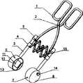
图1为本发明实施例1的结构示意图Fig. 1 is the structural representation of
图2为本发明实施例1中超声换能器9及焦距调节机构14的结Fig. 2 is the structure of
构示意图Structure diagram
图3为本发明实施例1中连接头5的结构示意图Fig. 3 is a schematic structural view of the
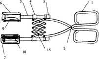
图4为本发明实施例2的结构示意图Fig. 4 is the structural representation of
图5为本发明实施例3的结构示意图Fig. 5 is the structural representation of
图6为本发明实施例4的结构示意图Fig. 6 is the structural representation of
图7为本发明实施例5的结构示意图Fig. 7 is the structural representation of
图8为本发明实施例6结构示意图Figure 8 is a schematic structural view of
图9为本发明实施例6中单节伸缩管21的结构示意图Figure 9 is a schematic structural view of the single-section
图10为本发明实施例6中超声治疗头中的支架10及其上的超声换能器9的结构示意图Figure 10 is a schematic structural view of the
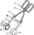
图11为本发明实施例7的结构示意图Figure 11 is a schematic structural view of
图12为本发明实施例8的结构示意图Figure 12 is a schematic structural view of
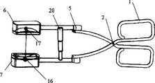
图13为本发明实施例9的结构示意图Figure 13 is a schematic structural view of
图14为本发明实施例和主机操控系统25相结合使用时的结构示意图Fig. 14 is a schematic structural diagram of the embodiment of the present invention when used in combination with the
图中:1-手柄 2—销钉 3—连接管 4—滑动套 5—连接头6—第一治疗头 7—第二治疗头 8—流体容器 9—超声换能器10—支架 11—透声膜 12—盖板 13—螺钉 14—焦距调节机构141—螺杆 142—密封圈 143—密封螺母 144—调节旋钮 145—紧固螺钉 15—连接块 16—槽口 17—半导体发光器 18—B超探头 19—温度传感器 20—伸缩管组件 21—单节伸缩管 22—转接头 23—销扣装置 24—小多孔软管 25—主机操控系统251—显示器 252—操作按钮 253—控制部件 254—水泵 255—水箱 256—脚轮 257—信号线 258—回水管 259—进水管26—大多孔软管In the figure: 1-handle 2-pin 3-connecting tube 4-sliding sleeve 5-connecting head 6-first treatment head 7-second treatment head 8-fluid container 9-ultrasonic transducer 10-bracket 11-acoustic Membrane 12—
具体实施方式Detailed ways
如图1-12所示,本发明包括手柄1、两个相对设置的超声治疗头以及使两个超声治疗头在随钳夹移动过程中始终保持平行移动的平动机构。手柄1为钳状,两个超声治疗头相对安装于钳状手柄1的前端头,其轴线重合。As shown in Figures 1-12, the present invention includes a
超声治疗头包括超声换能器9、可装有流体的流体容器8,超声换能器9置于流体容器8内,流体容器8的敞口处通过密封装置固定有透声膜11。The ultrasonic treatment head includes an
超声换能器9可采用聚焦或非聚焦换能器。聚焦换能器主要用于术中止血和治疗组织中较深部位的病灶如肝脏肿瘤、骨肿瘤以及深部肌肉瘤等,聚焦超声换能器可为单个圆形的压电陶瓷晶片加透镜聚焦,也可以是单个球面形、单弧面压电陶瓷晶片,还可以是由多个同一或不同尺寸的压电陶瓷晶片组合成的压电陶瓷阵列,其驱动方式可以是单一信号驱动,也可是多路信号按相位控制方式驱动;非聚焦换能器主要用于治疗皮肤病变以及皮肤浅表的病灶,非聚焦超声换能器可为单个平面压电陶瓷晶片,也可以为由多个同一或不同尺寸的平面压电陶瓷晶片组合成的压电陶瓷阵列,其驱动方式可以是单一信号驱动,也可是多路信号按相位控制方式驱动。The
超声换能器9中还可开有槽口16,在该槽口16中可固定半导体发光器或B超探头等,用以引导进行超声治疗。在两手柄头中间还可有固定手柄位置的锁扣装置。A
优选的是,该超声治疗头还可包括有温度传感器19,其固定于两个超声换能器夹紧目标组织的一面。Preferably, the ultrasonic treatment head may also include a
超声治疗头还可包括有连接管3,连接管3的一端与流体容器8连接,另一端通过连接头5与钳状手柄1的钳夹连接,所述平动机构连接在两相对的连接管3之间。所述连接头5与连接管3连接的一端有进出液通道及电信号通道,进出液通道及电信号通道都与超声治疗头连通。The ultrasonic treatment head can also include a connecting
下面结合实施例及附图,对本发明作进一步详细叙述。Below in conjunction with embodiment and accompanying drawing, the present invention is further described in detail.
以下实施例为本发明的非限定性实施例。The following examples are non-limiting examples of the invention.
实施例1:Example 1:
如图1所示,本发明包括手柄1、超声治疗头、平动机构。其中,手柄1为钳状,由销钉2连接手柄1的两个支柄,超声治疗头为两个,分别为第一治疗头6和第二治疗头7,其相对安装于钳状手柄1钳夹的前端头,两超声治疗头的轴线重合。As shown in Fig. 1, the present invention includes a
第一超声治疗头6和第二超声治疗头7包括可装有流体的流体容器8、超声换能器9、透声膜11、盖板12、连接管3,连接管3一端与超声换能器9连接,另一端与手柄1的钳夹相连,超声换能器9置于流体容器8内,透声膜11通过密封装置,即盖板12固定到流体容器8的敞口处。流体容器8中充满的流体为脱气水,本实施例中,流体采用纯净水,超声换能器采用可聚焦的单个球面形压电陶瓷晶片,用以治疗深部且体积较小的病灶。The first
如图2所示,超声换能器9置于支架10上,支架10与超声换能器9的焦距调节装置14连接,焦距调节装置14置于流体容器8上。As shown in FIG. 2 , the
焦距调节机构14包括螺杆141、密封圈142、密封螺母143、调节旋钮144和紧固螺钉145,螺杆141带凸台的一端和支架10螺纹连接,另外一端穿过流体容器8与密封螺母143连接,密封螺母143与调节旋钮144连接,调节旋钮144采用紧固螺钉145紧固,为了保证密封,在螺杆141穿过流体容器8的外壁处安装有密封圈142。旋转调节旋钮144,在螺杆141的带动下支架10作前后运动,从而也使得放置在支架10上的超声换能器9作前后运动,这种带焦距调节机构的超声换能器可适应在组织厚度相同的情况下满足不同病灶深度的治疗。The
第一治疗头6和第二治疗头7中的超声换能器9的频率可相同也可不同,且两个超声换能器分别由两套驱动机构进行驱动,治疗时,可以根据实际情况让一个超声治疗头参与治疗,也可同时让两个超声治疗头都参与治疗。The frequencies of the
为了能使本实施例中超声治疗钳的钳夹在任何开度下,两个超声治疗头始终处于平行状态,即保证在任何时候两个超声治疗头的轴线始终在一条钱上,手柄1的两个钳夹的之间设置有平动机构。In order to make the jaws of the ultrasonic treatment forceps in this embodiment be clamped at any opening, the two ultrasonic treatment heads are always in a parallel state, that is, to ensure that the axes of the two ultrasonic treatment heads are always on the same line at any time, and the handle 1 A translation mechanism is arranged between the two clamps.
平动机构的实现有很多种方法,如图1所示,本实施例中,采用平行四边形伸缩机构,由于平行四边形在任何情况下,不管其顶点如何移动,仍然保持为平行四边形,也就是说,其相对两边在任何情况下都保持平行。该平动机构设置于两个连接管3之间,由多个采用销钉铰接的连接块15构成,其最外端一角的连接块15与套在连接管3上可来回滑动的滑动套4铰接,外端另一角的连接块15固定在钳夹上。其中,滑动套4是保证平动机构在外力作用下能够自由伸缩必不可少的部件。There are many ways to realize the translational mechanism. As shown in Figure 1, in this embodiment, a parallelogram telescopic mechanism is adopted. Since the parallelogram remains a parallelogram no matter how its apex moves under any circumstances, that is to say , whose opposite sides remain parallel in all cases. The translation mechanism is arranged between two connecting
由于第一治疗头6、第二治疗头7分别固定在相对的两个连接管3上,因此手柄1的钳夹在任何开度下,两个连接管3均保持平行,这样,第一治疗头6和第二治疗头7始终能平行移动。钳夹与连接有超声治疗头的连接头5铰接在一起,手柄1的开合构成两超声治疗头做相对平行运动的动力源。Since the
图1中,连接管3穿过流体容器8的侧壁与流体容器8固定连接,连接管3的另一端通过连接头5与手柄1的钳夹连接。如图3所示,连接头5内部具有三个孔路,该三个孔路都与超声治疗头连通,分别作为超声治疗头9的进水通道、回水通道、电信号通道。因此,连接头5既是滑动套4的支承装置,又是本发明中电路和水路的通道。本实施例中,进水通道和回水通道都与流体容器8连通,流体容器8中的纯净水既作为超声藕合介质,同时又是超声换能器9的冷却液,通过纯净水的流动,可迅速带走治疗过程中超声换能器9产生的热量。In FIG. 1 , the connecting
本实施例中,治疗钳所有的活动关节均采用销钉2连接。销钉连接的目的是为了保证在活动关节处除一个旋转自由度外,其它方位的自由度都被限制,因此本发明不会产生扭动、串动等现象,以保证超声治疗头在钳夹进行开合运动时始终保持平衡。In this embodiment, all movable joints of the treatment forceps are connected by
如图14所示,本实施例超声治疗钳可以和一外部主机操控系统25相结合使用。两根小多孔软管24分别与两个连接头5相连,每个小多孔软管24具有与连接头5三个孔路相通的孔路,再通过一接头将两根小多孔软管24与一大多孔软管26相连,大多孔软管26内有与两根小多孔软管24的孔路相通的孔路,大多孔软管26与主机系统25相连。As shown in FIG. 14 , the ultrasonic therapy forceps of this embodiment can be used in combination with an external
如图13所示,主机操控系统25中,信号线257与控制部件253相连,用以给超声换能器9提供电信号;水泵254放置在水箱255上与控制部件253相连,在控制部件253的控制下水箱255中的纯净水进入进水管259中,进水管259与大多孔软管26中的进水通道相连,纯净水最终通过回水管258最终又回到水箱255中。As shown in Figure 13, in the
使用本实施例治疗钳时,如图14所示,首先推动脚轮256使得主机操控系统25靠近目标组织,根据手术的需要选择参与治疗的超声治疗头数目,如可以选定两个超声治疗头同时进行治疗,然后通过操控手柄1,使两个超声治疗头夹紧目标组织,再通过焦距调节机构14对超声换能器9的焦距进行调节;然后在连接头5的三个通道中,在控制部件253的控制下,信号线257的某一组分别提供电激励信号给两个超声换能器9,同时通过进水管259给流体容器8内注入纯净水作为超声藕合介质和超声换能器9的冷却介质,为了使水能得到充分利用,纯净水最终通过回水管258回收;平动机构在手柄1的带动下作伸缩运动时,两个超声治疗头始终保持平行,超声换能器9发射超声能量,最终在目标组织内形成凝固性坏死区域。若是为了止血目的使用本发明,则使超声波在手术需切割区域与保留区域之间聚焦形成一凝固性坏死区,使本区域内的组织坏死,血液凝固,医生用手术刀切除病灶区域时(比如切除肝脏等的病灶组织),切割的过程中不会失血过多,减少了输血的可能性,也减少了术后并发症的发生,若是治疗肿瘤等病灶,则最终使这些病灶失去增殖、浸润和转移的能力。When using the treatment forceps of this embodiment, as shown in Figure 14, at first promote
实施例2:Example 2:
如图4所示,本实施例和实施例1不同之处主要是本实施例中超声换能器采用可聚焦的单弧面压电陶瓷晶片,此种超声换能器主要用于术中止血以及对组织深部体积较大的病灶进行治疗。同时,本实施例中两个超声治疗头上没有焦距调节装置14,因此超声换能器9的支架10形状与实施例1中不同,支架10上有支撑脚,支撑脚固定在超声治疗头内,支撑脚的作用主要是使支架更牢固、稳定。As shown in Figure 4, the main difference between this embodiment and
本实施例其他结构及使用方法都与实施例1相同。Other structures and usage methods of this embodiment are the same as those of
实施例3:Example 3:
如图5所示,本实施例中,两个超声换能器9中开有槽口16,槽口16内通过粘接等方式固定有半导体发光器17,用以引导超声换能器9进行精确的治疗,在治疗前,操作者可根据半导体发光器17所发射光束的位置来定位超声治疗头在目标组织表面的位置,以确定治疗头的聚焦区域和半导体发光器17光束有交点的位置,以便进行精确的治疗。As shown in Figure 5, in this embodiment, there are
本实施例中,超声换能器9采用由多个同一或不同尺寸的压电陶瓷晶片组合成的压电陶瓷阵列,该阵列的驱动方式是多路信号按相位控制方式驱动,这样,操作者可以根据病灶的深浅等实际情况激励超声换能器9,使焦点更精确,能量更适合。In this embodiment, the
本发明超声治疗钳和主机操控系统25相结合使用时,信号线257中有一组提供电激励信号给两个超声换能器9,另有一组提供电激励信号给两个半导体发光器17。When the ultrasonic treatment forceps of the present invention are used in combination with the
本实施例的其它结构及使用方法均与实施例2相同。Other structures and usage methods of this embodiment are the same as those of
实施例4:Example 4:
如图6所示,超声换能器9上开有槽口16,槽口16中固定有超声成像设备,本实施例中,超声成像设备采用B超探头18,用以对目标组织成像,以引导本发明超声治疗钳的治疗。第一治疗头6和第二治疗头7中任一槽口16中都可以安装B超探头18,本实施例中,将其安装在第一治疗头6的槽口16中。As shown in Figure 6, a
该超声治疗钳和主机操控系统25相结合使用时,由B超探头18对目标组织成像,根据成像的结果,对目标组织进行治疗。When the ultrasonic treatment forceps are used in combination with the
本实施例其它结构及使用方法均与实施例2相同。Other structures and usage methods of this embodiment are the same as those of
实施例5:Example 5:
如图7所示,由于实际使用过程中因病灶大小和形状不同,要求超声换能器的聚焦方式也不一样,在连接头5与第一治疗头6、第二治疗头7之间有一个可旋转90°的转接头22,第一治疗头6、第二治疗头7可在转接头22上自由旋转,即可进行横向和纵向聚焦方式的转换。As shown in Figure 7, due to the different size and shape of the lesions in the actual use process, the focusing mode of the ultrasonic transducer is required to be different. There is a The
同时,在手柄1上还加有锁扣装置26,当平动机构在手柄1的带动下作伸缩运动到适当位置时,可用该锁扣装置26将两个手柄1的位置固定。At the same time, a
本实施例的其它结构及使用方法均与实施例2相同。Other structures and usage methods of this embodiment are the same as those of
实施例6:Embodiment 6:
如图8所示,本实施例平动机构采用伸缩管结构,即伸缩管组件20,该伸缩管组件20由直径大小不同的空心管套在一起组成,小空心管套在大空心管中并可以自由伸缩(与拉杆天线的原理相同)。图9为单节伸缩管21的结构示意图,每节空心管上都带有限位凸台,以防止伸缩过程中小空心管不会从套在其外的大空心管中拉出。这种不同直径的空心管根据治疗的需要可以有多个,为了保证能够自由伸缩滑动,伸缩管组件20至少采用两节不同直径的单节伸缩管21套装在一起组成。本实施例中采用三节单节伸缩管。As shown in Figure 8, the translational mechanism of this embodiment adopts a telescopic tube structure, that is, a
本实施例中,超声换能器9采用非聚焦的圆形压电陶瓷晶片,用于治疗皮肤病变以及浅表病灶等。如图10所示,超声换能器9固定在支架10上。由于超声换能器9的形状为圆形,因此两相对超声治疗头的外形也采用圆形。第一治疗头6和第二治疗头7上无焦距调节装置14,因此支架10的形状与实施例1不同,支架10带有支撑脚,支撑脚固定在超声治疗头内,支撑脚的作用主要是使支架牢固、稳定。In this embodiment, the
本实施例的其他结构及使用方法都与实施例1相同。Other structures and usage methods of this embodiment are the same as those of
本实施例中,第一治疗头6和第二治疗头7分别通过连接头5固定在手柄1两个钳夹的前端头,伸缩管组件20的两端分别固定在相对的两个连接管3上。当伸缩管组件20在手柄1的带动下作伸缩运动时,第一超声治疗头6和第二超声治疗头7始终保持平行移动。In this embodiment, the
实施例7:Embodiment 7:
如图11所示,本实施例除了平动机构采用伸缩管组件20外,其他结构及使用方法都与实施例3相同。As shown in FIG. 11 , in this embodiment, except that the translation mechanism adopts the
实施例8:Embodiment 8:
如图12所示,本实施例除了平动机构采用伸缩管组件20外,其他结构和使用方法均与实施例4相同。As shown in FIG. 12 , in this embodiment, except that the translation mechanism adopts the
实施例9:Embodiment 9:
如图13所示,本实施例中平动机构采用伸缩管组件20。此外,为了防止对目标组织造成灼伤,在第一治疗头6、第二治疗头7中包括有温度传感器19,其固定在两个超声换能器9夹紧目标组织的一面。由于膜片式温度传感器具有轻薄的特点,因此本实施例中采用膜片式温度传感器。As shown in FIG. 13 , the translation mechanism in this embodiment adopts a
本实施例的其它结构与实施例2相同。Other structures of this embodiment are the same as those of
如图14所示,当本实施例的超声治疗钳和主机系统25相结合使用时,信号线257中有一组提供电激励信号给两个超声换能器9,一组提供温度监测信号给温度传感器19,将其检测到的温度通过控制部件253处理后通过主机操控系统25中的显示器251显示出来,操作者根据显示的数据,以判断是否继续进行治疗,若需要停止治疗,则通过操作按钮252来结束治疗。As shown in Figure 14, when the ultrasonic treatment forceps of the present embodiment are used in combination with the
Claims (16)
Translated fromChinesePriority Applications (7)
| Application Number | Priority Date | Filing Date | Title |
|---|---|---|---|
| CNB2006100016325ACN100463660C (en) | 2006-01-18 | 2006-01-18 | Ultrasound Therapy Forceps |
| US12/161,219US8282581B2 (en) | 2006-01-18 | 2006-07-07 | Ultrasound treatment clamp |
| RU2008129651/14ARU2404828C2 (en) | 2006-01-18 | 2006-07-17 | Therapeutic ultrasonic clamp |
| JP2008550607AJP5021679B2 (en) | 2006-01-18 | 2006-07-17 | Ultrasound therapy clamp |
| CA002637403ACA2637403A1 (en) | 2006-01-18 | 2006-07-17 | Ultrasound treatment clamp |
| EP06761454AEP1974771A4 (en) | 2006-01-18 | 2006-07-17 | Ultrasonic treatment clamp |
| PCT/CN2006/001716WO2007082422A1 (en) | 2006-01-18 | 2006-07-17 | Ultrasonic treatment clamp |
Applications Claiming Priority (1)
| Application Number | Priority Date | Filing Date | Title |
|---|---|---|---|
| CNB2006100016325ACN100463660C (en) | 2006-01-18 | 2006-01-18 | Ultrasound Therapy Forceps |
Publications (2)
| Publication Number | Publication Date |
|---|---|
| CN101002692A CN101002692A (en) | 2007-07-25 |
| CN100463660Ctrue CN100463660C (en) | 2009-02-25 |
Family
ID=38287239
Family Applications (1)
| Application Number | Title | Priority Date | Filing Date |
|---|---|---|---|
| CNB2006100016325AActiveCN100463660C (en) | 2006-01-18 | 2006-01-18 | Ultrasound Therapy Forceps |
Country Status (7)
| Country | Link |
|---|---|
| US (1) | US8282581B2 (en) |
| EP (1) | EP1974771A4 (en) |
| JP (1) | JP5021679B2 (en) |
| CN (1) | CN100463660C (en) |
| CA (1) | CA2637403A1 (en) |
| RU (1) | RU2404828C2 (en) |
| WO (1) | WO2007082422A1 (en) |
Cited By (2)
| Publication number | Priority date | Publication date | Assignee | Title |
|---|---|---|---|---|
| CN105073045A (en)* | 2013-03-13 | 2015-11-18 | 柯惠Lp公司 | Clamp ultrasound probe for lung surgery |
| CN108472054A (en)* | 2015-11-30 | 2018-08-31 | 索尼公司 | Hand-held apparatus for endoscopic surgery |
Families Citing this family (202)
| Publication number | Priority date | Publication date | Assignee | Title |
|---|---|---|---|---|
| US7364577B2 (en) | 2002-02-11 | 2008-04-29 | Sherwood Services Ag | Vessel sealing system |
| ES2262639T3 (en) | 2001-04-06 | 2006-12-01 | Sherwood Services Ag | SHUTTER AND DIVIDER OF GLASSES WITH BUMPER MEMBERS N OCONDUCTIVES. |
| US11229472B2 (en) | 2001-06-12 | 2022-01-25 | Cilag Gmbh International | Modular battery powered handheld surgical instrument with multiple magnetic position sensors |
| US7367976B2 (en) | 2003-11-17 | 2008-05-06 | Sherwood Services Ag | Bipolar forceps having monopolar extension |
| US8182501B2 (en) | 2004-02-27 | 2012-05-22 | Ethicon Endo-Surgery, Inc. | Ultrasonic surgical shears and method for sealing a blood vessel using same |
| US20060079879A1 (en) | 2004-10-08 | 2006-04-13 | Faller Craig N | Actuation mechanism for use with an ultrasonic surgical instrument |
| US7628791B2 (en) | 2005-08-19 | 2009-12-08 | Covidien Ag | Single action tissue sealer |
| US20070191713A1 (en) | 2005-10-14 | 2007-08-16 | Eichmann Stephen E | Ultrasonic device for cutting and coagulating |
| US7621930B2 (en) | 2006-01-20 | 2009-11-24 | Ethicon Endo-Surgery, Inc. | Ultrasound medical instrument having a medical ultrasonic blade |
| US8911460B2 (en) | 2007-03-22 | 2014-12-16 | Ethicon Endo-Surgery, Inc. | Ultrasonic surgical instruments |
| US8057498B2 (en) | 2007-11-30 | 2011-11-15 | Ethicon Endo-Surgery, Inc. | Ultrasonic surgical instrument blades |
| US20080234709A1 (en) | 2007-03-22 | 2008-09-25 | Houser Kevin L | Ultrasonic surgical instrument and cartilage and bone shaping blades therefor |
| US8226675B2 (en) | 2007-03-22 | 2012-07-24 | Ethicon Endo-Surgery, Inc. | Surgical instruments |
| US8142461B2 (en) | 2007-03-22 | 2012-03-27 | Ethicon Endo-Surgery, Inc. | Surgical instruments |
| CN101322869B (en)* | 2007-06-14 | 2010-06-02 | 重庆融海超声医学工程研究中心有限公司 | Retaining type ultrasonic treatment gun and ultrasonic beauty treatment equipment containing the treatment gun |
| US8257377B2 (en) | 2007-07-27 | 2012-09-04 | Ethicon Endo-Surgery, Inc. | Multiple end effectors ultrasonic surgical instruments |
| US8808319B2 (en) | 2007-07-27 | 2014-08-19 | Ethicon Endo-Surgery, Inc. | Surgical instruments |
| US8523889B2 (en) | 2007-07-27 | 2013-09-03 | Ethicon Endo-Surgery, Inc. | Ultrasonic end effectors with increased active length |
| US8882791B2 (en) | 2007-07-27 | 2014-11-11 | Ethicon Endo-Surgery, Inc. | Ultrasonic surgical instruments |
| US8348967B2 (en) | 2007-07-27 | 2013-01-08 | Ethicon Endo-Surgery, Inc. | Ultrasonic surgical instruments |
| US8430898B2 (en) | 2007-07-31 | 2013-04-30 | Ethicon Endo-Surgery, Inc. | Ultrasonic surgical instruments |
| US9044261B2 (en) | 2007-07-31 | 2015-06-02 | Ethicon Endo-Surgery, Inc. | Temperature controlled ultrasonic surgical instruments |
| US8252012B2 (en) | 2007-07-31 | 2012-08-28 | Ethicon Endo-Surgery, Inc. | Ultrasonic surgical instrument with modulator |
| US8512365B2 (en) | 2007-07-31 | 2013-08-20 | Ethicon Endo-Surgery, Inc. | Surgical instruments |
| US20090036759A1 (en)* | 2007-08-01 | 2009-02-05 | Ault Timothy E | Collapsible noninvasive analyzer method and apparatus |
| USD594983S1 (en) | 2007-10-05 | 2009-06-23 | Ethicon Endo-Surgery, Inc. | Handle assembly for surgical instrument |
| EP2217157A2 (en) | 2007-10-05 | 2010-08-18 | Ethicon Endo-Surgery, Inc. | Ergonomic surgical instruments |
| US10010339B2 (en) | 2007-11-30 | 2018-07-03 | Ethicon Llc | Ultrasonic surgical blades |
| US7901423B2 (en) | 2007-11-30 | 2011-03-08 | Ethicon Endo-Surgery, Inc. | Folded ultrasonic end effectors with increased active length |
| US20100004536A1 (en)* | 2008-07-03 | 2010-01-07 | Avner Rosenberg | Method and apparatus for ultrasound tissue treatment |
| US20100017750A1 (en) | 2008-07-16 | 2010-01-21 | Avner Rosenberg | User interface |
| US9089360B2 (en) | 2008-08-06 | 2015-07-28 | Ethicon Endo-Surgery, Inc. | Devices and techniques for cutting and coagulating tissue |
| US8058771B2 (en) | 2008-08-06 | 2011-11-15 | Ethicon Endo-Surgery, Inc. | Ultrasonic device for cutting and coagulating with stepped output |
| US8142473B2 (en) | 2008-10-03 | 2012-03-27 | Tyco Healthcare Group Lp | Method of transferring rotational motion in an articulating surgical instrument |
| US9700339B2 (en) | 2009-05-20 | 2017-07-11 | Ethicon Endo-Surgery, Inc. | Coupling arrangements and methods for attaching tools to ultrasonic surgical instruments |
| US8650728B2 (en) | 2009-06-24 | 2014-02-18 | Ethicon Endo-Surgery, Inc. | Method of assembling a transducer for a surgical instrument |
| US8246618B2 (en) | 2009-07-08 | 2012-08-21 | Tyco Healthcare Group Lp | Electrosurgical jaws with offset knife |
| US8461744B2 (en) | 2009-07-15 | 2013-06-11 | Ethicon Endo-Surgery, Inc. | Rotating transducer mount for ultrasonic surgical instruments |
| US8663220B2 (en) | 2009-07-15 | 2014-03-04 | Ethicon Endo-Surgery, Inc. | Ultrasonic surgical instruments |
| US9017326B2 (en) | 2009-07-15 | 2015-04-28 | Ethicon Endo-Surgery, Inc. | Impedance monitoring apparatus, system, and method for ultrasonic surgical instruments |
| EP2467116A4 (en) | 2009-08-20 | 2015-08-12 | Syneron Medical Ltd | Method and apparatus for non- invasive aesthetic treatment of skin and sub-dermis. |
| US10441345B2 (en) | 2009-10-09 | 2019-10-15 | Ethicon Llc | Surgical generator for ultrasonic and electrosurgical devices |
| USRE47996E1 (en) | 2009-10-09 | 2020-05-19 | Ethicon Llc | Surgical generator for ultrasonic and electrosurgical devices |
| US9168054B2 (en) | 2009-10-09 | 2015-10-27 | Ethicon Endo-Surgery, Inc. | Surgical generator for ultrasonic and electrosurgical devices |
| US11090104B2 (en) | 2009-10-09 | 2021-08-17 | Cilag Gmbh International | Surgical generator for ultrasonic and electrosurgical devices |
| US9050093B2 (en) | 2009-10-09 | 2015-06-09 | Ethicon Endo-Surgery, Inc. | Surgical generator for ultrasonic and electrosurgical devices |
| US10172669B2 (en) | 2009-10-09 | 2019-01-08 | Ethicon Llc | Surgical instrument comprising an energy trigger lockout |
| JP2013508065A (en)* | 2009-10-24 | 2013-03-07 | シネロン メディカル リミテッド | Method and apparatus for real-time monitoring of organizational layers |
| US8388647B2 (en)* | 2009-10-28 | 2013-03-05 | Covidien Lp | Apparatus for tissue sealing |
| US8579928B2 (en) | 2010-02-11 | 2013-11-12 | Ethicon Endo-Surgery, Inc. | Outer sheath and blade arrangements for ultrasonic surgical instruments |
| US8961547B2 (en) | 2010-02-11 | 2015-02-24 | Ethicon Endo-Surgery, Inc. | Ultrasonic surgical instruments with moving cutting implement |
| US8531064B2 (en) | 2010-02-11 | 2013-09-10 | Ethicon Endo-Surgery, Inc. | Ultrasonically powered surgical instruments with rotating cutting implement |
| US8469981B2 (en) | 2010-02-11 | 2013-06-25 | Ethicon Endo-Surgery, Inc. | Rotatable cutting implement arrangements for ultrasonic surgical instruments |
| US8486096B2 (en) | 2010-02-11 | 2013-07-16 | Ethicon Endo-Surgery, Inc. | Dual purpose surgical instrument for cutting and coagulating tissue |
| US8419759B2 (en) | 2010-02-11 | 2013-04-16 | Ethicon Endo-Surgery, Inc. | Ultrasonic surgical instrument with comb-like tissue trimming device |
| US8951272B2 (en) | 2010-02-11 | 2015-02-10 | Ethicon Endo-Surgery, Inc. | Seal arrangements for ultrasonically powered surgical instruments |
| US8323302B2 (en) | 2010-02-11 | 2012-12-04 | Ethicon Endo-Surgery, Inc. | Methods of using ultrasonically powered surgical instruments with rotatable cutting implements |
| US8382782B2 (en) | 2010-02-11 | 2013-02-26 | Ethicon Endo-Surgery, Inc. | Ultrasonic surgical instruments with partially rotating blade and fixed pad arrangement |
| US9259234B2 (en) | 2010-02-11 | 2016-02-16 | Ethicon Endo-Surgery, Llc | Ultrasonic surgical instruments with rotatable blade and hollow sheath arrangements |
| GB2480498A (en) | 2010-05-21 | 2011-11-23 | Ethicon Endo Surgery Inc | Medical device comprising RF circuitry |
| US8795327B2 (en) | 2010-07-22 | 2014-08-05 | Ethicon Endo-Surgery, Inc. | Electrosurgical instrument with separate closure and cutting members |
| US9192431B2 (en) | 2010-07-23 | 2015-11-24 | Ethicon Endo-Surgery, Inc. | Electrosurgical cutting and sealing instrument |
| US8979890B2 (en) | 2010-10-01 | 2015-03-17 | Ethicon Endo-Surgery, Inc. | Surgical instrument with jaw member |
| US8888809B2 (en) | 2010-10-01 | 2014-11-18 | Ethicon Endo-Surgery, Inc. | Surgical instrument with jaw member |
| US8485974B2 (en)* | 2010-11-15 | 2013-07-16 | National Health Research Institutes | Multiple-frequency ultrasonic phased array driving system |
| US9113940B2 (en) | 2011-01-14 | 2015-08-25 | Covidien Lp | Trigger lockout and kickback mechanism for surgical instruments |
| US8968293B2 (en) | 2011-04-12 | 2015-03-03 | Covidien Lp | Systems and methods for calibrating power measurements in an electrosurgical generator |
| CN102728008A (en)* | 2011-04-15 | 2012-10-17 | 江苏赛达医疗科技有限公司 | Ultrasonic transducer zooming mechanism used for superficial treatment |
| US9259265B2 (en) | 2011-07-22 | 2016-02-16 | Ethicon Endo-Surgery, Llc | Surgical instruments for tensioning tissue |
| USD700967S1 (en) | 2011-08-23 | 2014-03-11 | Covidien Ag | Handle for portable surgical device |
| US9333025B2 (en) | 2011-10-24 | 2016-05-10 | Ethicon Endo-Surgery, Llc | Battery initialization clip |
| USD687549S1 (en) | 2011-10-24 | 2013-08-06 | Ethicon Endo-Surgery, Inc. | Surgical instrument |
| WO2013105079A2 (en) | 2012-01-11 | 2013-07-18 | Syneron Medical Ltd. | Large area body shaping applicator |
| USD680220S1 (en) | 2012-01-12 | 2013-04-16 | Coviden IP | Slider handle for laparoscopic device |
| WO2013119545A1 (en) | 2012-02-10 | 2013-08-15 | Ethicon-Endo Surgery, Inc. | Robotically controlled surgical instrument |
| US9439668B2 (en) | 2012-04-09 | 2016-09-13 | Ethicon Endo-Surgery, Llc | Switch arrangements for ultrasonic surgical instruments |
| US9226766B2 (en) | 2012-04-09 | 2016-01-05 | Ethicon Endo-Surgery, Inc. | Serial communication protocol for medical device |
| US9241731B2 (en) | 2012-04-09 | 2016-01-26 | Ethicon Endo-Surgery, Inc. | Rotatable electrical connection for ultrasonic surgical instruments |
| US9237921B2 (en) | 2012-04-09 | 2016-01-19 | Ethicon Endo-Surgery, Inc. | Devices and techniques for cutting and coagulating tissue |
| US9724118B2 (en) | 2012-04-09 | 2017-08-08 | Ethicon Endo-Surgery, Llc | Techniques for cutting and coagulating tissue for ultrasonic surgical instruments |
| CN102670256A (en)* | 2012-05-16 | 2012-09-19 | 北京航空航天大学 | Heel width measurement device and method suitable for ultrasonic osteoporosis tester |
| US20140005705A1 (en) | 2012-06-29 | 2014-01-02 | Ethicon Endo-Surgery, Inc. | Surgical instruments with articulating shafts |
| US9820768B2 (en) | 2012-06-29 | 2017-11-21 | Ethicon Llc | Ultrasonic surgical instruments with control mechanisms |
| US20140005702A1 (en) | 2012-06-29 | 2014-01-02 | Ethicon Endo-Surgery, Inc. | Ultrasonic surgical instruments with distally positioned transducers |
| US9393037B2 (en) | 2012-06-29 | 2016-07-19 | Ethicon Endo-Surgery, Llc | Surgical instruments with articulating shafts |
| US9326788B2 (en) | 2012-06-29 | 2016-05-03 | Ethicon Endo-Surgery, Llc | Lockout mechanism for use with robotic electrosurgical device |
| US9408622B2 (en) | 2012-06-29 | 2016-08-09 | Ethicon Endo-Surgery, Llc | Surgical instruments with articulating shafts |
| US9198714B2 (en) | 2012-06-29 | 2015-12-01 | Ethicon Endo-Surgery, Inc. | Haptic feedback devices for surgical robot |
| US9351754B2 (en) | 2012-06-29 | 2016-05-31 | Ethicon Endo-Surgery, Llc | Ultrasonic surgical instruments with distally positioned jaw assemblies |
| US9226767B2 (en) | 2012-06-29 | 2016-01-05 | Ethicon Endo-Surgery, Inc. | Closed feedback control for electrosurgical device |
| US9283045B2 (en) | 2012-06-29 | 2016-03-15 | Ethicon Endo-Surgery, Llc | Surgical instruments with fluid management system |
| EP2900158B1 (en) | 2012-09-28 | 2020-04-15 | Ethicon LLC | Multi-function bi-polar forceps |
| US9095367B2 (en) | 2012-10-22 | 2015-08-04 | Ethicon Endo-Surgery, Inc. | Flexible harmonic waveguides/blades for surgical instruments |
| US10201365B2 (en) | 2012-10-22 | 2019-02-12 | Ethicon Llc | Surgeon feedback sensing and display methods |
| US20140135804A1 (en) | 2012-11-15 | 2014-05-15 | Ethicon Endo-Surgery, Inc. | Ultrasonic and electrosurgical devices |
| US10226273B2 (en) | 2013-03-14 | 2019-03-12 | Ethicon Llc | Mechanical fasteners for use with surgical energy devices |
| US9241728B2 (en) | 2013-03-15 | 2016-01-26 | Ethicon Endo-Surgery, Inc. | Surgical instrument with multiple clamping mechanisms |
| US9814514B2 (en) | 2013-09-13 | 2017-11-14 | Ethicon Llc | Electrosurgical (RF) medical instruments for cutting and coagulating tissue |
| CN103496346B (en)* | 2013-10-15 | 2015-08-12 | 金华市融昌工具有限公司 | Roof boxes toggle rod type connection fixing clamp |
| US9265926B2 (en) | 2013-11-08 | 2016-02-23 | Ethicon Endo-Surgery, Llc | Electrosurgical devices |
| GB2521229A (en) | 2013-12-16 | 2015-06-17 | Ethicon Endo Surgery Inc | Medical device |
| GB2521228A (en) | 2013-12-16 | 2015-06-17 | Ethicon Endo Surgery Inc | Medical device |
| US9795436B2 (en) | 2014-01-07 | 2017-10-24 | Ethicon Llc | Harvesting energy from a surgical generator |
| US9554854B2 (en) | 2014-03-18 | 2017-01-31 | Ethicon Endo-Surgery, Llc | Detecting short circuits in electrosurgical medical devices |
| US10463421B2 (en) | 2014-03-27 | 2019-11-05 | Ethicon Llc | Two stage trigger, clamp and cut bipolar vessel sealer |
| US10092310B2 (en) | 2014-03-27 | 2018-10-09 | Ethicon Llc | Electrosurgical devices |
| US9737355B2 (en) | 2014-03-31 | 2017-08-22 | Ethicon Llc | Controlling impedance rise in electrosurgical medical devices |
| US9913680B2 (en) | 2014-04-15 | 2018-03-13 | Ethicon Llc | Software algorithms for electrosurgical instruments |
| CN104013434A (en)* | 2014-06-12 | 2014-09-03 | 苏州森斯凌传感技术有限公司 | Ultrasonic probe cooling system with host computer wireless control function |
| CN104013432A (en)* | 2014-06-12 | 2014-09-03 | 苏州森斯凌传感技术有限公司 | Cooling system of ultrasonic probe |
| CN104013431A (en)* | 2014-06-12 | 2014-09-03 | 苏州森斯凌传感技术有限公司 | Ultrasonic probe circulating cooling system with NET transmission control conducted by host |
| CN104013426A (en)* | 2014-06-12 | 2014-09-03 | 苏州森斯凌传感技术有限公司 | Ultrasonic probe circulation cooling device based on GSM wireless control |
| US9700333B2 (en) | 2014-06-30 | 2017-07-11 | Ethicon Llc | Surgical instrument with variable tissue compression |
| US10285724B2 (en) | 2014-07-31 | 2019-05-14 | Ethicon Llc | Actuation mechanisms and load adjustment assemblies for surgical instruments |
| US10639092B2 (en) | 2014-12-08 | 2020-05-05 | Ethicon Llc | Electrode configurations for surgical instruments |
| US10159524B2 (en) | 2014-12-22 | 2018-12-25 | Ethicon Llc | High power battery powered RF amplifier topology |
| US10245095B2 (en) | 2015-02-06 | 2019-04-02 | Ethicon Llc | Electrosurgical instrument with rotation and articulation mechanisms |
| US10342602B2 (en) | 2015-03-17 | 2019-07-09 | Ethicon Llc | Managing tissue treatment |
| US10321950B2 (en) | 2015-03-17 | 2019-06-18 | Ethicon Llc | Managing tissue treatment |
| US10595929B2 (en) | 2015-03-24 | 2020-03-24 | Ethicon Llc | Surgical instruments with firing system overload protection mechanisms |
| US10314638B2 (en) | 2015-04-07 | 2019-06-11 | Ethicon Llc | Articulating radio frequency (RF) tissue seal with articulating state sensing |
| US10034684B2 (en) | 2015-06-15 | 2018-07-31 | Ethicon Llc | Apparatus and method for dissecting and coagulating tissue |
| US11020140B2 (en) | 2015-06-17 | 2021-06-01 | Cilag Gmbh International | Ultrasonic surgical blade for use with ultrasonic surgical instruments |
| US11129669B2 (en) | 2015-06-30 | 2021-09-28 | Cilag Gmbh International | Surgical system with user adaptable techniques based on tissue type |
| US11051873B2 (en) | 2015-06-30 | 2021-07-06 | Cilag Gmbh International | Surgical system with user adaptable techniques employing multiple energy modalities based on tissue parameters |
| US10357303B2 (en) | 2015-06-30 | 2019-07-23 | Ethicon Llc | Translatable outer tube for sealing using shielded lap chole dissector |
| US11141213B2 (en) | 2015-06-30 | 2021-10-12 | Cilag Gmbh International | Surgical instrument with user adaptable techniques |
| US10898256B2 (en) | 2015-06-30 | 2021-01-26 | Ethicon Llc | Surgical system with user adaptable techniques based on tissue impedance |
| US10034704B2 (en) | 2015-06-30 | 2018-07-31 | Ethicon Llc | Surgical instrument with user adaptable algorithms |
| US10154852B2 (en) | 2015-07-01 | 2018-12-18 | Ethicon Llc | Ultrasonic surgical blade with improved cutting and coagulation features |
| US10194973B2 (en) | 2015-09-30 | 2019-02-05 | Ethicon Llc | Generator for digitally generating electrical signal waveforms for electrosurgical and ultrasonic surgical instruments |
| US10959771B2 (en) | 2015-10-16 | 2021-03-30 | Ethicon Llc | Suction and irrigation sealing grasper |
| US10595930B2 (en) | 2015-10-16 | 2020-03-24 | Ethicon Llc | Electrode wiping surgical device |
| US10959806B2 (en) | 2015-12-30 | 2021-03-30 | Ethicon Llc | Energized medical device with reusable handle |
| US10179022B2 (en) | 2015-12-30 | 2019-01-15 | Ethicon Llc | Jaw position impedance limiter for electrosurgical instrument |
| US10575892B2 (en) | 2015-12-31 | 2020-03-03 | Ethicon Llc | Adapter for electrical surgical instruments |
| US11051840B2 (en) | 2016-01-15 | 2021-07-06 | Ethicon Llc | Modular battery powered handheld surgical instrument with reusable asymmetric handle housing |
| US11129670B2 (en) | 2016-01-15 | 2021-09-28 | Cilag Gmbh International | Modular battery powered handheld surgical instrument with selective application of energy based on button displacement, intensity, or local tissue characterization |
| US12193698B2 (en) | 2016-01-15 | 2025-01-14 | Cilag Gmbh International | Method for self-diagnosing operation of a control switch in a surgical instrument system |
| US11229471B2 (en) | 2016-01-15 | 2022-01-25 | Cilag Gmbh International | Modular battery powered handheld surgical instrument with selective application of energy based on tissue characterization |
| US10716615B2 (en) | 2016-01-15 | 2020-07-21 | Ethicon Llc | Modular battery powered handheld surgical instrument with curved end effectors having asymmetric engagement between jaw and blade |
| US10555769B2 (en) | 2016-02-22 | 2020-02-11 | Ethicon Llc | Flexible circuits for electrosurgical instrument |
| US10646269B2 (en) | 2016-04-29 | 2020-05-12 | Ethicon Llc | Non-linear jaw gap for electrosurgical instruments |
| US10856934B2 (en) | 2016-04-29 | 2020-12-08 | Ethicon Llc | Electrosurgical instrument with electrically conductive gap setting and tissue engaging members |
| US10702329B2 (en) | 2016-04-29 | 2020-07-07 | Ethicon Llc | Jaw structure with distal post for electrosurgical instruments |
| US10485607B2 (en) | 2016-04-29 | 2019-11-26 | Ethicon Llc | Jaw structure with distal closure for electrosurgical instruments |
| US10987156B2 (en) | 2016-04-29 | 2021-04-27 | Ethicon Llc | Electrosurgical instrument with electrically conductive gap setting member and electrically insulative tissue engaging members |
| US10456193B2 (en) | 2016-05-03 | 2019-10-29 | Ethicon Llc | Medical device with a bilateral jaw configuration for nerve stimulation |
| CN105943133B (en)* | 2016-05-31 | 2018-07-06 | 山东山大附属生殖医院有限公司 | A kind of cyclic annular tighten is clamped |
| US10245064B2 (en) | 2016-07-12 | 2019-04-02 | Ethicon Llc | Ultrasonic surgical instrument with piezoelectric central lumen transducer |
| US10893883B2 (en) | 2016-07-13 | 2021-01-19 | Ethicon Llc | Ultrasonic assembly for use with ultrasonic surgical instruments |
| US10842522B2 (en) | 2016-07-15 | 2020-11-24 | Ethicon Llc | Ultrasonic surgical instruments having offset blades |
| US10376305B2 (en) | 2016-08-05 | 2019-08-13 | Ethicon Llc | Methods and systems for advanced harmonic energy |
| US10285723B2 (en) | 2016-08-09 | 2019-05-14 | Ethicon Llc | Ultrasonic surgical blade with improved heel portion |
| USD847990S1 (en) | 2016-08-16 | 2019-05-07 | Ethicon Llc | Surgical instrument |
| US10736649B2 (en) | 2016-08-25 | 2020-08-11 | Ethicon Llc | Electrical and thermal connections for ultrasonic transducer |
| US10952759B2 (en) | 2016-08-25 | 2021-03-23 | Ethicon Llc | Tissue loading of a surgical instrument |
| US10751117B2 (en) | 2016-09-23 | 2020-08-25 | Ethicon Llc | Electrosurgical instrument with fluid diverter |
| US10603064B2 (en) | 2016-11-28 | 2020-03-31 | Ethicon Llc | Ultrasonic transducer |
| US11266430B2 (en) | 2016-11-29 | 2022-03-08 | Cilag Gmbh International | End effector control and calibration |
| US11033325B2 (en) | 2017-02-16 | 2021-06-15 | Cilag Gmbh International | Electrosurgical instrument with telescoping suction port and debris cleaner |
| US10799284B2 (en) | 2017-03-15 | 2020-10-13 | Ethicon Llc | Electrosurgical instrument with textured jaws |
| US11497546B2 (en) | 2017-03-31 | 2022-11-15 | Cilag Gmbh International | Area ratios of patterned coatings on RF electrodes to reduce sticking |
| US10603117B2 (en) | 2017-06-28 | 2020-03-31 | Ethicon Llc | Articulation state detection mechanisms |
| US10820920B2 (en) | 2017-07-05 | 2020-11-03 | Ethicon Llc | Reusable ultrasonic medical devices and methods of their use |
| US10925628B2 (en)* | 2017-09-18 | 2021-02-23 | Novuson Surgical, Inc. | Tissue engagement apparatus for theapeutic ultrasound apparatus and method |
| US11484358B2 (en) | 2017-09-29 | 2022-11-01 | Cilag Gmbh International | Flexible electrosurgical instrument |
| US11033323B2 (en) | 2017-09-29 | 2021-06-15 | Cilag Gmbh International | Systems and methods for managing fluid and suction in electrosurgical systems |
| US11490951B2 (en) | 2017-09-29 | 2022-11-08 | Cilag Gmbh International | Saline contact with electrodes |
| FR3075380B1 (en)* | 2017-12-18 | 2020-01-17 | Safran Aircraft Engines | TOOLS FOR NON-DESTRUCTIVE INSPECTION OF A FLAT PART |
| US11950797B2 (en) | 2019-12-30 | 2024-04-09 | Cilag Gmbh International | Deflectable electrode with higher distal bias relative to proximal bias |
| US12336747B2 (en) | 2019-12-30 | 2025-06-24 | Cilag Gmbh International | Method of operating a combination ultrasonic / bipolar RF surgical device with a combination energy modality end-effector |
| US20210196357A1 (en) | 2019-12-30 | 2021-07-01 | Ethicon Llc | Electrosurgical instrument with asynchronous energizing electrodes |
| US11452525B2 (en) | 2019-12-30 | 2022-09-27 | Cilag Gmbh International | Surgical instrument comprising an adjustment system |
| US12076006B2 (en) | 2019-12-30 | 2024-09-03 | Cilag Gmbh International | Surgical instrument comprising an orientation detection system |
| US11812957B2 (en) | 2019-12-30 | 2023-11-14 | Cilag Gmbh International | Surgical instrument comprising a signal interference resolution system |
| US12082808B2 (en) | 2019-12-30 | 2024-09-10 | Cilag Gmbh International | Surgical instrument comprising a control system responsive to software configurations |
| US12114912B2 (en) | 2019-12-30 | 2024-10-15 | Cilag Gmbh International | Non-biased deflectable electrode to minimize contact between ultrasonic blade and electrode |
| US11786294B2 (en) | 2019-12-30 | 2023-10-17 | Cilag Gmbh International | Control program for modular combination energy device |
| US11779329B2 (en) | 2019-12-30 | 2023-10-10 | Cilag Gmbh International | Surgical instrument comprising a flex circuit including a sensor system |
| US20210196362A1 (en) | 2019-12-30 | 2021-07-01 | Ethicon Llc | Electrosurgical end effectors with thermally insulative and thermally conductive portions |
| US11696776B2 (en) | 2019-12-30 | 2023-07-11 | Cilag Gmbh International | Articulatable surgical instrument |
| US11937863B2 (en) | 2019-12-30 | 2024-03-26 | Cilag Gmbh International | Deflectable electrode with variable compression bias along the length of the deflectable electrode |
| US11937866B2 (en) | 2019-12-30 | 2024-03-26 | Cilag Gmbh International | Method for an electrosurgical procedure |
| US12064109B2 (en) | 2019-12-30 | 2024-08-20 | Cilag Gmbh International | Surgical instrument comprising a feedback control circuit |
| US12023086B2 (en) | 2019-12-30 | 2024-07-02 | Cilag Gmbh International | Electrosurgical instrument for delivering blended energy modalities to tissue |
| US11911063B2 (en) | 2019-12-30 | 2024-02-27 | Cilag Gmbh International | Techniques for detecting ultrasonic blade to electrode contact and reducing power to ultrasonic blade |
| US11986201B2 (en) | 2019-12-30 | 2024-05-21 | Cilag Gmbh International | Method for operating a surgical instrument |
| US11779387B2 (en) | 2019-12-30 | 2023-10-10 | Cilag Gmbh International | Clamp arm jaw to minimize tissue sticking and improve tissue control |
| US11786291B2 (en) | 2019-12-30 | 2023-10-17 | Cilag Gmbh International | Deflectable support of RF energy electrode with respect to opposing ultrasonic blade |
| US11684412B2 (en) | 2019-12-30 | 2023-06-27 | Cilag Gmbh International | Surgical instrument with rotatable and articulatable surgical end effector |
| US12053224B2 (en) | 2019-12-30 | 2024-08-06 | Cilag Gmbh International | Variation in electrode parameters and deflectable electrode to modify energy density and tissue interaction |
| US12343063B2 (en) | 2019-12-30 | 2025-07-01 | Cilag Gmbh International | Multi-layer clamp arm pad for enhanced versatility and performance of a surgical device |
| US12262937B2 (en) | 2019-12-30 | 2025-04-01 | Cilag Gmbh International | User interface for surgical instrument with combination energy modality end-effector |
| US11660089B2 (en) | 2019-12-30 | 2023-05-30 | Cilag Gmbh International | Surgical instrument comprising a sensing system |
| US11944366B2 (en) | 2019-12-30 | 2024-04-02 | Cilag Gmbh International | Asymmetric segmented ultrasonic support pad for cooperative engagement with a movable RF electrode |
| JP7449132B2 (en)* | 2020-03-17 | 2024-03-13 | 京セラ株式会社 | Ultrasonic therapy device |
| EP4292541A4 (en)* | 2021-02-10 | 2024-07-10 | FUJIFILM Corporation | Ultrasonic treatment tool device and method for driving same |
| CN113180782B (en)* | 2021-04-23 | 2022-05-24 | 清华大学 | Clamping Ultrasonic Thrombolysis Device |
| CN113350703B (en)* | 2021-07-14 | 2022-04-29 | 武汉博激世纪科技有限公司 | Hand-held type semiconductor laser therapeutic instrument |
| US11957342B2 (en) | 2021-11-01 | 2024-04-16 | Cilag Gmbh International | Devices, systems, and methods for detecting tissue and foreign objects during a surgical operation |
| CN115778491B (en)* | 2022-10-24 | 2025-09-23 | 中国医学科学院北京协和医院 | Long-handled purse-string pliers with flexible angle adjustment |
Citations (6)
| Publication number | Priority date | Publication date | Assignee | Title |
|---|---|---|---|---|
| US4662068A (en)* | 1985-11-14 | 1987-05-05 | Eli Polonsky | Suture fusing and cutting apparatus |
| US6083159A (en)* | 1995-05-22 | 2000-07-04 | Ths International, Inc. | Methods and devices for providing acoustic hemostasis |
| US6139561A (en)* | 1998-04-16 | 2000-10-31 | Olympus Optical Co., Ltd. | Ultrasonic medical instrument |
| JP2001037771A (en)* | 1999-08-03 | 2001-02-13 | Olympus Optical Co Ltd | Ultrasonic treatment device |
| US6432067B1 (en)* | 1997-10-31 | 2002-08-13 | University Of Washington | Method and apparatus for medical procedures using high-intensity focused ultrasound |
| JP2002306503A (en)* | 2001-04-10 | 2002-10-22 | Aloka Co Ltd | Ultrasonic surgery instrument |
Family Cites Families (13)
| Publication number | Priority date | Publication date | Assignee | Title |
|---|---|---|---|---|
| US4711240A (en)* | 1986-05-15 | 1987-12-08 | Duke University Patents Foundation | Surgical dissector |
| DE3707097A1 (en)* | 1986-12-05 | 1988-06-09 | S & G Implants Gmbh | PLIERS FOR SPREADING SPINE BODIES |
| US6312426B1 (en)* | 1997-05-30 | 2001-11-06 | Sherwood Services Ag | Method and system for performing plate type radiofrequency ablation |
| US6102909A (en)* | 1997-08-26 | 2000-08-15 | Ethicon, Inc. | Scissorlike electrosurgical cutting instrument |
| US6096033A (en)* | 1998-07-20 | 2000-08-01 | Tu; Hosheng | Medical device having ultrasonic ablation capability |
| US6582451B1 (en)* | 1999-03-16 | 2003-06-24 | The University Of Sydney | Device for use in surgery |
| JP2001095813A (en)* | 1999-09-29 | 2001-04-10 | Olympus Optical Co Ltd | Bipolar coagulation incision appliance |
| US20030069502A1 (en)* | 2001-05-29 | 2003-04-10 | Makin Inder Raj. S. | Ultrasound feedback in medically-treated patients |
| US7322995B2 (en)* | 2002-09-13 | 2008-01-29 | Damage Control Surgical Technologies, Inc. | Method and apparatus for vascular and visceral clipping |
| US6739068B1 (en)* | 2003-01-06 | 2004-05-25 | Pilling Weck Incorporated | Pliers with jaw spacing and load measuring readings |
| JP4343778B2 (en)* | 2004-06-16 | 2009-10-14 | オリンパス株式会社 | Ultrasonic surgical device |
| US7553284B2 (en)* | 2005-02-02 | 2009-06-30 | Vaitekunas Jeffrey J | Focused ultrasound for pain reduction |
| US20070038115A1 (en)* | 2005-08-12 | 2007-02-15 | Quigley David P | High intensity ultrasound apparatus methods and systems |
- 2006
- 2006-01-18CNCNB2006100016325Apatent/CN100463660C/enactiveActive
- 2006-07-07USUS12/161,219patent/US8282581B2/enactiveActive
- 2006-07-17EPEP06761454Apatent/EP1974771A4/ennot_activeWithdrawn
- 2006-07-17WOPCT/CN2006/001716patent/WO2007082422A1/enactiveApplication Filing
- 2006-07-17RURU2008129651/14Apatent/RU2404828C2/enactive
- 2006-07-17CACA002637403Apatent/CA2637403A1/ennot_activeAbandoned
- 2006-07-17JPJP2008550607Apatent/JP5021679B2/ennot_activeExpired - Fee Related
Patent Citations (6)
| Publication number | Priority date | Publication date | Assignee | Title |
|---|---|---|---|---|
| US4662068A (en)* | 1985-11-14 | 1987-05-05 | Eli Polonsky | Suture fusing and cutting apparatus |
| US6083159A (en)* | 1995-05-22 | 2000-07-04 | Ths International, Inc. | Methods and devices for providing acoustic hemostasis |
| US6432067B1 (en)* | 1997-10-31 | 2002-08-13 | University Of Washington | Method and apparatus for medical procedures using high-intensity focused ultrasound |
| US6139561A (en)* | 1998-04-16 | 2000-10-31 | Olympus Optical Co., Ltd. | Ultrasonic medical instrument |
| JP2001037771A (en)* | 1999-08-03 | 2001-02-13 | Olympus Optical Co Ltd | Ultrasonic treatment device |
| JP2002306503A (en)* | 2001-04-10 | 2002-10-22 | Aloka Co Ltd | Ultrasonic surgery instrument |
Cited By (2)
| Publication number | Priority date | Publication date | Assignee | Title |
|---|---|---|---|---|
| CN105073045A (en)* | 2013-03-13 | 2015-11-18 | 柯惠Lp公司 | Clamp ultrasound probe for lung surgery |
| CN108472054A (en)* | 2015-11-30 | 2018-08-31 | 索尼公司 | Hand-held apparatus for endoscopic surgery |
Also Published As
| Publication number | Publication date |
|---|---|
| EP1974771A4 (en) | 2011-12-21 |
| US8282581B2 (en) | 2012-10-09 |
| RU2008129651A (en) | 2010-02-27 |
| CN101002692A (en) | 2007-07-25 |
| CA2637403A1 (en) | 2007-07-26 |
| US20090275865A1 (en) | 2009-11-05 |
| JP2009523507A (en) | 2009-06-25 |
| JP5021679B2 (en) | 2012-09-12 |
| EP1974771A1 (en) | 2008-10-01 |
| WO2007082422A1 (en) | 2007-07-26 |
| RU2404828C2 (en) | 2010-11-27 |
Similar Documents
| Publication | Publication Date | Title |
|---|---|---|
| CN100463660C (en) | Ultrasound Therapy Forceps | |
| US6007499A (en) | Method and apparatus for medical procedures using high-intensity focused ultrasound | |
| CN111093461B (en) | Therapeutic ultrasound apparatus and methods | |
| US7591794B2 (en) | Therapy probe | |
| US8622937B2 (en) | Controlled high efficiency lesion formation using high intensity ultrasound | |
| US5882302A (en) | Methods and devices for providing acoustic hemostasis | |
| US20120035473A1 (en) | Laparoscopic hifu probe | |
| US20050256405A1 (en) | Ultrasound-based procedure for uterine medical treatment | |
| WO2008031303A1 (en) | An automatically clamping ultrasonic therapeutic device | |
| CA2484515A1 (en) | Solid hydrogel coupling for ultrasound imaging and therapy | |
| JP2005516663A (en) | Apparatus and method for treating gynecological disease using ultrasonic medical device operating in transverse mode | |
| JP2009502304A (en) | Surgical instruments | |
| CN115515470A (en) | Hemostatic methods and devices | |
| CN117440841A (en) | Aspiration and irrigation valves and perfusion methods in robotic surgical systems | |
| WO2022033172A1 (en) | Folding-type electrode assembly and folding-type hemostatis instrument | |
| CN101912302A (en) | Hard microwave gall bladder mirror system | |
| CN1141064C (en) | Excising device resulting in small incision | |
| TWI882915B (en) | Supporting device for surgery | |
| Tavakkoli et al. | Laparoscopic high intensity focused ultrasound: application to kidney ablation | |
| Shiozawa et al. | A newly developed endoscopic ultrasonic aspiration system and its clinical application | |
| HK40029574A (en) | Therapeutic ultrasound apparatus and method |
Legal Events
| Date | Code | Title | Description |
|---|---|---|---|
| C06 | Publication | ||
| PB01 | Publication | ||
| C10 | Entry into substantive examination | ||
| SE01 | Entry into force of request for substantive examination | ||
| C14 | Grant of patent or utility model | ||
| GR01 | Patent grant | ||
| C56 | Change in the name or address of the patentee | Owner name:CHONGQING HAIFU MEDICAL TECHNOLOGY CO., LTD. Free format text:FORMER NAME: CHONGQING HAIFU (HIFU) TECHNOLOGY CO., LTD. | |
| CP01 | Change in the name or title of a patent holder | Address after:401121 No. 1 Pine Road, man Town, Chongqing, Yubei District Patentee after:Chongqing Haifu Medical Technology Co., Ltd. Address before:401121 No. 1 Pine Road, man Town, Chongqing, Yubei District Patentee before:Haifu (HIFU) Technology Co., Ltd., Chongqing | |
| CP02 | Change in the address of a patent holder | Address after:No. 359, jingdongfang Avenue, Beibei District, Chongqing 400714 Patentee after:Chongqing Haifu Medical Technology Co.,Ltd. Address before:401121 No. 1 Pine Road, man Town, Chongqing, Yubei District Patentee before:Chongqing Haifu Medical Technology Co.,Ltd. | |
| CP02 | Change in the address of a patent holder |