CN100460824C - Photodetector Array Arrangement for Optical Encoders - Google Patents
Photodetector Array Arrangement for Optical EncodersDownload PDFInfo
- Publication number
- CN100460824C CN100460824CCNB2005100053245ACN200510005324ACN100460824CCN 100460824 CCN100460824 CCN 100460824CCN B2005100053245 ACNB2005100053245 ACN B2005100053245ACN 200510005324 ACN200510005324 ACN 200510005324ACN 100460824 CCN100460824 CCN 100460824C
- Authority
- CN
- China
- Prior art keywords
- track
- photodetector
- photodetectors
- index
- optical encoder
- Prior art date
- Legal status (The legal status is an assumption and is not a legal conclusion. Google has not performed a legal analysis and makes no representation as to the accuracy of the status listed.)
- Expired - Fee Related
Links
Images


Classifications
- G—PHYSICS
- G01—MEASURING; TESTING
- G01D—MEASURING NOT SPECIALLY ADAPTED FOR A SPECIFIC VARIABLE; ARRANGEMENTS FOR MEASURING TWO OR MORE VARIABLES NOT COVERED IN A SINGLE OTHER SUBCLASS; TARIFF METERING APPARATUS; MEASURING OR TESTING NOT OTHERWISE PROVIDED FOR
- G01D5/00—Mechanical means for transferring the output of a sensing member; Means for converting the output of a sensing member to another variable where the form or nature of the sensing member does not constrain the means for converting; Transducers not specially adapted for a specific variable
- G01D5/26—Mechanical means for transferring the output of a sensing member; Means for converting the output of a sensing member to another variable where the form or nature of the sensing member does not constrain the means for converting; Transducers not specially adapted for a specific variable characterised by optical transfer means, i.e. using infrared, visible, or ultraviolet light
- G01D5/32—Mechanical means for transferring the output of a sensing member; Means for converting the output of a sensing member to another variable where the form or nature of the sensing member does not constrain the means for converting; Transducers not specially adapted for a specific variable characterised by optical transfer means, i.e. using infrared, visible, or ultraviolet light with attenuation or whole or partial obturation of beams of light
- G01D5/34—Mechanical means for transferring the output of a sensing member; Means for converting the output of a sensing member to another variable where the form or nature of the sensing member does not constrain the means for converting; Transducers not specially adapted for a specific variable characterised by optical transfer means, i.e. using infrared, visible, or ultraviolet light with attenuation or whole or partial obturation of beams of light the beams of light being detected by photocells
- G01D5/36—Forming the light into pulses
- G01D5/366—Particular pulse shapes
Landscapes
- Physics & Mathematics (AREA)
- General Physics & Mathematics (AREA)
- Optical Transform (AREA)
Abstract
Translated fromChinese
Description
Translated fromChinese技术领域technical field
本发明涉及光学编码器。The present invention relates to optical encoders.
背景技术Background technique
光学编码器被用于例如监测诸如曲轴之类的轴的运动。光学编码器可以在轴的位置和/或旋转数方面来监测轴的运动。光学编码器通常使用附着在轴上的码盘来在轴和码盘旋转时调制光。随着光通过含有透明区和不透明区图案的码盘上的轨道,光被调制。随着光响应于码盘的旋转而被调制,从接收了经调制光的光电探测器阵列产生一串电信号。这些电信号被用来确定轴的位置和/或旋转数。Optical encoders are used, for example, to monitor the movement of a shaft such as a crankshaft. Optical encoders can monitor shaft motion in terms of shaft position and/or revolutions. Optical encoders typically use a code wheel attached to a shaft to modulate light as the shaft and code wheel rotate. The light is modulated as it passes through a track on a code wheel containing a pattern of transparent and opaque regions. As the light is modulated in response to the rotation of the code wheel, a train of electrical signals is generated from the array of photodetectors that receive the modulated light. These electrical signals are used to determine the position and/or rotation of the shaft.
码盘上分别的位置轨道和索引(index)轨道被用来确定位置和旋转数。位置轨道和索引轨道必须与相应的位置轨道和索引轨道光电探测器阵列精确对准,以获得可靠的结果。因为每个轨道都必须与其相应的光电探测器阵列对准,所以随着轨道数量的增加,对准任务变得更为困难。此外,光学位置编码器的一些应用要求更高分辨率的位置信息,这就要求更小的轨道和光电探测器阵列。更小的轨道和光电探测器阵列给对准任务增加了额外的难题。Separate position and index tracks on the code wheel are used to determine position and number of revolutions. The position track and index track must be precisely aligned with the corresponding position track and index track photodetector arrays to obtain reliable results. Because each track must be aligned with its corresponding photodetector array, the alignment task becomes more difficult as the number of tracks increases. In addition, some applications of optical position encoders require higher resolution position information, which requires smaller track and photodetector arrays. Smaller tracks and photodetector arrays add additional challenges to the alignment task.
发明内容Contents of the invention
一种光学编码器使用光电探测器阵列,该光电探测器阵列具有至少两个表面积不同的光电探测器,所述光电探测器当同时被发光二级管照亮时,产生不同量的光电流。因为这些光电探测器在被同时照亮时产生不同量的光电流,所以光电探测器产生可以被用于标引诸如码盘之类的编码元件的明确结果。An optical encoder uses a photodetector array having at least two photodetectors of different surface areas that produce different amounts of photocurrent when simultaneously illuminated by light emitting diodes. Because these photodetectors generate different amounts of photocurrent when illuminated simultaneously, the photodetectors produce unambiguous results that can be used to index an encoding element such as a code wheel.
另一种光学编码器使用一个与索引轨道对准的索引光电探测器以及另一个与编码元件的位置轨道对准的索引光电探测器,以标引编码元件。Another type of optical encoder uses an index photodetector aligned with the index track and another index photodetector aligned with the position track of the encoding element to index the encoding element.
结合以示例方式图示了本发明的原理的附图,从以下的详细描述,本发明的其他方面及优点将变的更加清楚。Other aspects and advantages of the invention will become more apparent from the following detailed description, taken in conjunction with the accompanying drawings, illustrating by way of example the principles of the invention.
附图说明Description of drawings
图1示出了用于测量轴的旋转运动的光学编码器系统。Figure 1 shows an optical encoder system for measuring the rotational motion of a shaft.
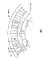
图2示出了含有位置轨道和索引轨道的码盘的一部分。Figure 2 shows a part of a code wheel containing a position track and an index track.
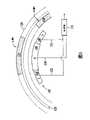
图3示出了与码盘的各个位置轨道和索引轨道(例如图2中示出的位置轨道和索引轨道)相对应的位置轨道和索引轨道光电探测器阵列的一个实施例。FIG. 3 shows an embodiment of a position track and index track photodetector array corresponding to respective position tracks and index tracks of a code wheel (eg, the position track and index track shown in FIG. 2 ).
图4示出了与相应的码盘的各个位置轨道和索引轨道相关的图3的位置光电探测器阵列和索引光电探测器阵列。Figure 4 shows the position photodetector array and the index photodetector array of Figure 3 in relation to the respective position and index tracks of the code wheel.
图5示出了与索引轨道光电探测器阵列相关的索引轨道的两个位置,其中索引特征是透明的。Figure 5 shows two positions of the indexing track relative to the indexing track photodetector array, where the indexing features are transparent.
图6示出了与索引轨道光电探测器阵列相关的索引轨道的两个位置,其中索引特征是不透明的。Figure 6 shows two positions of the indexing track relative to the indexing track photodetector array, where the indexing features are opaque.
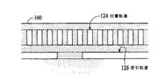
图7示出了含有线性位置轨道和索引轨道的线性编码元件的一个实施例,其中索引特征是透明的。Figure 7 shows an embodiment of a linear encoding element containing a linear position track and an index track, where the index features are transparent.
图8示出了与线性编码元件的各个位置轨道和索引轨道相关的位置光电探测器阵列和索引光电探测器阵列。Figure 8 shows a position photodetector array and an index photodetector array associated with each position track and index track of a linear encoding element.
图9示出了与线性编码元件的位置轨道和索引轨道相关的位置光电探测器和索引光电探测器的一个实施例,其中索引光电探测器分布在索引轨道及位置轨道之间。Fig. 9 shows an embodiment of position photodetectors and index photodetectors associated with a position track and an index track of a linear encoding element, wherein the index photodetectors are distributed between the index track and the position track.
图10示出了与线性编码元件的位置轨道和索引轨道相关的位置光电探测器和索引光电探测器的另一个实施例,其中索引光电探测器分布在索引轨道与位置轨道之间。Fig. 10 shows another embodiment of position photodetectors and index photodetectors associated with the position track and index track of a linear encoding element, wherein the index photodetectors are distributed between the index track and the position track.
以下说明中,类似的参考标号被用来标识类似的元素。In the following description, similar reference numerals are used to identify similar elements.
具体实施方式Detailed ways
图1示出了用于测量轴的旋转运动的光学编码器系统100。光学编码器系统包括马达110、轴112、码盘114和编码器116。码盘含有至少一个轨道(未示出),编码器包括由至少一个发光二级管构成的光源118及与轨道对准的光电探测器阵列120。编码器还包括信号处理逻辑122,用于处理从光电探测器阵列输出的电信号以测量轴的旋转运动。马达、轴、码盘和编码器在光学位置编码器领域中是公知的。具体地,参见美国专利4,451,731、4,691,101及5,241,172,它们通过引用被结合于此。Figure 1 shows an
图2示出了含有位置轨道124和索引轨道126的码盘114的一部分。位置轨道和索引轨道是与码盘同心的环形轨道。位置轨道包括始终围绕码盘的透明区128和不透明区130的连续重复图案。位置轨道对光调制,以测量码盘及轴112的位置改变。在图2的实施例中,位置轨道的透明区和不透明区具有相同的周向尺寸(也称为宽度尺寸)。透明区和不透明区的宽度尺寸(由跨度“x”指示)是希望的分辨率的函数。透明区和不透明区的径向尺寸(这里称为高度尺寸)(由跨度“y”指示)是产生足量光电流所要求的面积量的函数(例如,要求的光电流越大,则要求的面积越大,从而因为面积等于“x”乘“y”,所以需要“y”越大)。以下说明中,位置轨道的高度等同于位置轨道的透明区的高度。如本领域熟知的,位置轨道可以使用其他透明区和不透明区的图案来调制光。FIG. 2 shows a portion of
图2中所示的索引轨道126是含有至少一个作为索引特征的不透明区134的主要透明的轨道。索引轨道被用于测量码盘和轴的旋转。例如,索引轨道可以被用于指示旋转的结束和/或用于计数旋转数。如本领域所知,索引轨道可以利用其他透明区和不透明区的图案来调制光。例如,索引轨道可以是包括至少一个作为索引特征的透明区的主要不透明的轨道。索引特征的径向尺寸和周向尺寸(这里也分别称为高度尺寸和宽度尺寸)是光敏面积和分辨率的函数。在以下说明中,索引轨道的高度等同于透明区136或索引轨道区的高度。以下将更详细地描述使用索引轨道来测量旋转。The indexing
图3示出了与码盘的各个位置轨道和索引轨道124和126(例如图2中示出的位置轨道和索引轨道)相对应的位置轨道和索引轨道光电探测器阵列140和142的实施例。位置轨道光电探测器阵列包括与相应的位置轨道(位置轨道由虚线124指示)对准的一系列光电探测器144。每个光电探测器都具有相同的表面积及相同的径向尺寸(这里也称为高度尺寸)。需要注意的是,光电探测器的侧边缘基本上沿着从码盘的中心辐射的线。FIG. 3 shows an embodiment of position track and index
图3所示的位置轨道光电探测器144以A、B、A/、B/的重复图案被标记,其中“A/”读作“A杠”,“B/”读作“B杠”。光电探测器及由光电探测器产生的相应的电信号的这种指定是本领域熟知的。位置轨道光电探测器的周向尺寸(也被称作宽度尺寸)与相应的位置轨道的透明区和不透明区的宽度尺寸相关。在图3的实施例中,每个位置轨道光电探测器的宽度是相应的位置轨道的透明区和不透明区的宽度的一半。The
索引轨道光电探测器阵列142包括与相应的索引轨道(索引轨道由虚线126指示)对准的中心光电探测器146和两个侧光电探测器148。侧光电探测器的位置直接与中心光电探测器相邻。中心光电探测器被标记为“I/”,读作“I杠”,侧光电探测器被标记为“I”。光电探测器及由光电探测器产生的相应电信号的这种指定是本领域熟知的。在图3的实施例中,中心光电探测器具有比两个侧光电探测器的组合的表面积更大的表面积。中心光电探测器具有比两个侧光电探测器的组合的表面积更大的表面积,使得随着码盘旋转,索引轨道的索引特征可以被容易的识别。后面将参考图5及图6详细描述不同的表面积对识别索引特征的影响。Index
图4示出了图3的与相应的码盘的各个位置轨道和索引轨道124和126相关的位置光电探测器阵列和索引光电探测器阵列140和142。参考位置轨道,码盘包括分别是透明区和不透明区128和130的图案。如上所述,每个透明区和不透明区的宽度尺寸与两个光电探测器144的组合的宽度相同。在图4中,位置轨道的透明区和不透明区与位置轨道光电探测器144对准,以清楚地图示光电探测器的尺寸与位置轨道的特征之间的关系。FIG. 4 shows the position and
对于索引轨道126,码盘的索引轨道部分除了一个不透明区134(即,索引特征)之外,都是透明区136。在图4的实施例中,索引特征的宽度与中心光电探测器146的宽度相同,并且这两个元件周向对准,以清楚地图示尺寸关系。For
位置轨道124和相应的光电探测器阵列140的操作涉及随着码盘旋转对光进行调制,以及在光电探测器144处检测光。与位置轨道相关的光电探测器的物理布局使得所产生的电信号彼此90度地被相移。信号被成对组合以形成正交推挽信号。这种操作在美国专利4,691,101中被详细描述,其通过引用被结合于此。Operation of the
参考图5和图6描述索引轨道126和相应的光电探测器阵列142的操作。图5示出了与索引轨道光电探测器阵列相关的索引轨道的两个位置。在图5的实施例中,索引轨道是主要透明的,具有与光电探测器阵列的中心光电探测器146宽度尺寸相同的不透明特征134。此图还示出了与光电探测器阵列相关的信号通道150和152以及处理逻辑154(如,比较器)。在位置A,索引轨道的不透明索引特征与中心光电探测器对准。当不透明索引特征与中心光电探测器对准时,来自光源(未示出)的光被阻挡以避免击中中心光电探测器,因此由两个侧光电探测器148产生的光电流的量大于由中心光电探测器产生的光电流。从两个侧光电探测器和中心光电探测器产生的光电流在比较器处被连续地互相比较。比较器输出信号,指示哪种光电探测器(“I/”或“I”)输出了最大的光电流。The operation of the
在图5的实施例中,当索引特征处于位置A时,光电流I比光电流I/大,从比较器输出逻辑“1”。当索引特征处于位置B(例如,不阻挡光击中光电探测器阵列)时,光电流I比光电流I/小,从比较器输出逻辑“0”。在位置B处,因为中心光电探测器的表面积比两个侧光电探测器的组合的表面积更大,所以光电流I/比光电流I大。如果I/光电探测器的表面积并不比I光电探测器的组合的表面积更大,则当I及I/光电探测器被同时照亮时,编码器可能产生不确定的结果。通过监测比较器的输出,监测了码盘和轴的旋转。In the embodiment of FIG. 5, when the index feature is at position A, the photocurrent I is greater than the photocurrent I/, and a logic "1" is output from the comparator. When the index feature is in position B (eg, not blocking light from hitting the photodetector array), the photocurrent I is smaller than the photocurrent I/, and a logic "0" is output from the comparator. At position B, the photocurrent I/ is greater than the photocurrent I because the center photodetector has a larger surface area than the combined surface area of the two side photodetectors. If the surface area of the I/photodetector is not greater than the combined surface area of the I photodetector, the encoder may produce indeterminate results when the I and I/photodetector are illuminated simultaneously. By monitoring the output of the comparator, the rotation of the code wheel and shaft is monitored.
图6示出了与索引轨道光电探测器阵列142相关的索引轨道126的两个位置。在图6的实施例中,索引轨道是主要不透明的,具有与光电探测器阵列的中心光电探测器146宽度尺寸相同的透明索引特征156。此图还示出了与光电探测器阵列相关的信号通道150和152以及处理逻辑154(例如,比较器)。偏压158被施加给用于侧光电探测器148的信号通道(例如,信号通道152)。在位置A处,索引轨道的透明索引特征与中心光电探测器对准。当透明索引特征与中心光电探测器对准时,来自光源(未示出)的光主要击中中心光电探测器,因此由中心光电探测器产生的光电流的量比由两个侧光电探测器产生的光电流大。FIG. 6 shows two positions of
当索引特征处于位置A时,因为光电流I/比光电流I大,所以从比较器输出逻辑“1”。当索引特征在处于位置B(例如,没有光击中光电探测器阵列)时,因为施加到I信号上的偏压,光电流I比光电流I/大。结果,从比较器输出逻辑“0”。在此情况下,施加到I信号上的偏压使得I光电流大于I/光电流,而不论中心光电探测器具有比两个侧光电探测器的组合的表面积更大的表面积的事实。通过监测比较器的输出,可以监测码盘和轴的旋转。尽管透明索引特征的宽度与中心光电探测器的宽度相同,但是透明索引特征的宽度也可以被增加,直到光电探测器阵列的总宽度,而仍然提供所需的响应。When the index feature is at position A, a logic "1" is output from the comparator because the photocurrent I/ is larger than the photocurrent I. When the index feature is in position B (eg, no light hitting the photodetector array), the photocurrent I is greater than the photocurrent I/ because of the bias voltage applied to the I signal. As a result, logic "0" is output from the comparator. In this case, the bias applied to the I signal causes I photocurrent to be greater than I/photocurrent, regardless of the fact that the center photodetector has a larger surface area than the combined surface area of the two side photodetectors. By monitoring the output of the comparator, the rotation of the code wheel and shaft can be monitored. Although the width of the transparent index feature is the same as that of the central photodetector, the width of the transparent index feature can also be increased up to the total width of the photodetector array and still provide the desired response.
尽管图5及图6利用了光电探测器表面积的不同以产生不同的输出信号,但是也可以通过“I”光电探测器的不透明部分,或者通过相比于“I/”光电探测器(例如,中心电探测器146),减小入射到“I”光电探测器(例如,两个侧光电探测器148)上的光的量,以产生不同的输出信号。一般原理是:当索引轨道光电探测器阵列被同等地照亮时,光电流“I/”要高于光电流“I”。Although Figures 5 and 6 take advantage of the difference in photodetector surface area to generate different output signals, it can also be achieved by the opaque portion of the "I" photodetector, or by comparison to the "I/" photodetector (eg, center photodetector 146), reducing the amount of light incident on the "I" photodetectors (eg, the two side photodetectors 148) to produce different output signals. The general principle is that when the indexed track photodetector arrays are equally illuminated, the photocurrent "I/" is higher than the photocurrent "I".
如这里使用的,术语“轨道”包括编码元件或码盘的不透明区和透明区两者。As used herein, the term "track" includes both opaque and transparent regions of an encoding element or code wheel.
尽管在测量旋转运动方面描述了光学编码器系统100及相应的码盘114,但是相同的原理还可以应用于测量线性运动。图7示出了包括线性位置轨道和索引轨道124和126的线性编码元件160的实施例。尽管在图2至图6中使用码盘描述了位置轨道和索引轨道以及相应的光电探测器阵列,但是相同的原理也可以应用于线性编码元件。此外,在图3至图6中示出的光电探测器阵列可以被制成线性的,而非弯曲的。图8示出了与线性编码元件的位置轨道和索引轨道相关的位置光电探测器阵列和索引光电探测器阵列。Although the
在另一实施例中,被用于索引的光电探测器阵列分布在索引轨道与位置轨道之间。例如,索引光电探测器146和148的至少一个与位置轨道光电探测器阵列相集成。图9示出了与线性编码元件的位置轨道和索引轨道124和126相关的位置光电探测器和索引光电探测器的实施例。在图9的实施例中,I/光电探测器146位于B/与A光电探测器之间,并具有与位置轨道的不透明区130和透明区128的组合的宽度相等的宽度尺寸。在操作中,I/光电探测器将总是被照亮一半,而只有当索引特征134(例如,索引轨道的索引窗)通过I光电探测器时,I光电探测器148才被照亮。当索引轨道的不透明区136覆盖I光电探测器时(未示出),来自I/光电探测器的光电流比来自I光电探测器的光电流大(例如,I/>I),从相应的比较器的输出是逻辑低。但是,当索引轨道的索引特征暴露给I光电探测器的比位置轨道暴露给I/光电探测器的更多时,来自I光电探测器的光电流比来自I/光电探测器的光电流大(例如,I>I/),从相应的比较器的输出是逻辑高。In another embodiment, the photodetector array used for indexing is distributed between the index track and the position track. For example, at least one of
需要注意的是I/光电探测器146不需要在索引点被照亮一半。例如,位置轨道可以被设计为在索引点完全覆盖I/光电二极管。在不规则宽的不透明区通过位置光电探测器阵列时,这样做在位置轨道中产生一些误差。但是,如果有足够的A、B、A/和B/光电探测器的循环,误差可以被平衡掉(average out)。图10中示出了另一种编码元件设计,其含有一个额外长的不透明区,并依靠光电二极管的多个循环以平衡掉误差。在图10的实施例中,位置轨道的应该是透明的一个区实际上是不透明的。此外,位置轨道和索引轨道124和126被构成使得当索引轨道的透明区的一个边缘与I光电探测器148的一个边缘对准时,在I/光电探测器146之上的不透明区的相对边缘与I/光电探测器的一个边缘对准。在此结构中,当一个索引光电探测器将被露出时,其他的光电探测器正好将被阻挡。Note that I/
通过改变I/与I光电探测器之间的相对表面积,可以获得不同的索引脉冲宽度。在图9及图10的实施例中,I/与I光电探测器的位置以及编码元件的照亮区和不透明区可以交换,以在索引点产生逻辑高或逻辑低。而且,与位置轨道相对的I与I/光电探测器的位置可以被操控以设置索引信道将触发时的点。图9及图10的实施例可以被应用于码盘,以测量旋转运动。By varying the relative surface area between the I/ and I photodetectors, different index pulse widths can be obtained. In the embodiments of FIGS. 9 and 10 , the positions of the I/ and I photodetectors and the illuminated and opaque regions of the encoding element can be swapped to generate a logic high or logic low at the index point. Also, the position of the I and I/photodetectors relative to the position track can be manipulated to set the point at which the index channel will trigger. The embodiments of Figures 9 and 10 can be applied to a code wheel to measure rotational motion.
在图2至图10的实施例中,尽管索引光电探测器的中心光电探测器146和位置光电探测器144的宽度尺寸与各个位置轨道和索引轨道124和126的区域的宽度尺寸相匹配,或者与其多倍匹配,但是在位置光电探测器阵列和索引光电探测器阵列两者中的光电探测器的高度尺寸小于各个轨道的透明区的高度尺寸。如图4所示,位置轨道光电探测器的高度小于位置轨道的高度,索引轨道光电探测器的高度小于索引轨道的高度。光电探测器的高度尺寸比相应的轨道的透明区的高度尺寸小,以便在光电探测器阵列与相应的轨道之间提供对准公差。因为径向未对准可能使得光电探测器仅被部分照射,从而引起由于被部分照射的光电探测器而产生的不当低的光电流,所以轨道与光电探测器阵列之间的对准是重要的。不当低的光电流可能触发索引信号被错误的发出多次或者根本不发出。由光电探测器的小的高度尺寸提供的对准公差使得光电探测器和轨道能够承受一定程度的径向未对准,而不会不利地影响光电流的产生。在现有的编码器系统中,光电探测器的高度尺寸与相应的轨道相同,结果,在光电探测器与轨道之间的任何径向未对准都可能引起得到的光电流的不利改变。尽管光电探测器的高度尺寸被描述为小于轨道的高度,但这并不是必须的。In the embodiment of FIGS. 2 to 10, although the width dimension of the
在本实施例中,轨道124和126与各个光电探测器阵列140和142被径向对准,使得光电探测器处于相应轨道的中间。例如,如图4所示,光电探测器阵列位于各个轨道的中间。在相应轨道的中间,径向对准各个光电探测器阵列平衡了在光电探测器阵列两侧的对准公差。In this embodiment, the
尽管已经描述和图示了本发明的具体实施例,但是本发明并不限于如此描述和图示的部件的特定形式及布置。本发明的范围由所附的权利要求及其等同物界定。Although specific embodiments of the invention have been described and illustrated, the invention is not limited to the specific form and arrangement of parts so described and illustrated. The scope of the invention is defined by the appended claims and their equivalents.
Claims (16)
Translated fromChineseApplications Claiming Priority (2)
| Application Number | Priority Date | Filing Date | Title |
|---|---|---|---|
| US10/829,565US7126108B2 (en) | 2004-04-22 | 2004-04-22 | Photodetector array arrangement for optical encoders |
| US10/829,565 | 2004-04-22 |
Publications (2)
| Publication Number | Publication Date |
|---|---|
| CN1690663A CN1690663A (en) | 2005-11-02 |
| CN100460824Ctrue CN100460824C (en) | 2009-02-11 |
Family
ID=35135502
Family Applications (1)
| Application Number | Title | Priority Date | Filing Date |
|---|---|---|---|
| CNB2005100053245AExpired - Fee RelatedCN100460824C (en) | 2004-04-22 | 2005-01-31 | Photodetector Array Arrangement for Optical Encoders |
Country Status (2)
| Country | Link |
|---|---|
| US (1) | US7126108B2 (en) |
| CN (1) | CN100460824C (en) |
Families Citing this family (16)
| Publication number | Priority date | Publication date | Assignee | Title |
|---|---|---|---|---|
| US20070120047A1 (en)* | 2005-11-25 | 2007-05-31 | Wong Weng F | Ring-configured photodiode array and optical encoders using the same |
| JP2007170826A (en)* | 2005-12-19 | 2007-07-05 | Orion Denki Kk | Optical encoder |
| US7304294B2 (en)* | 2006-02-09 | 2007-12-04 | Avago Technologis General Ip (Singapore) Pte Ltd | Reflective encoder with reduced background noise |
| US7400269B2 (en)* | 2006-11-09 | 2008-07-15 | Avago Technologies Ecbu Ip Pte Ltd | Coding element with integrated limit switch |
| US20090207450A1 (en)* | 2008-02-19 | 2009-08-20 | Kabushiki Kaisha Toshiba | Image scanning apparatus, shading correction method, and shading correction program |
| US8173950B2 (en)* | 2008-02-19 | 2012-05-08 | Avago Technologies Ecbu Ip (Singapore) Pte. Ltd. | Single track optical encoder |
| US7795576B2 (en)* | 2008-12-23 | 2010-09-14 | Avago Technologies Ecbu Ip (Singapore) Pte. Ltd. | Single dome lens reflective optical encoder |
| EP2312274A1 (en)* | 2009-10-09 | 2011-04-20 | Baumer Innotec AG | Locator with multi-turn positioning |
| EP2309232B1 (en)* | 2009-10-09 | 2015-07-22 | Baumer IVO GmbH & Co. KG | Locator with multi-turn positioning |
| US8188420B2 (en)* | 2009-11-14 | 2012-05-29 | Avago Technologies Ecbu Ip (Singapore) Pte. Ltd. | High resolution optical encoder systems having a set of light detecting elements each comprising a pair of complementary detectors (as amended) |
| EP2842225B1 (en)* | 2012-04-25 | 2022-02-23 | Sanofi-Aventis Deutschland GmbH | Apparatus comprising electromechanical device and motion detector and method for operating apparatus |
| US10551223B2 (en)* | 2017-03-20 | 2020-02-04 | Tt Electronics Plc | Method and apparatus for configurable photodetector array patterning for optical encoders |
| DE102019109469A1 (en) | 2019-04-10 | 2020-10-15 | Vishay Semiconductor Gmbh | Optical encoder |
| WO2022016448A1 (en)* | 2020-07-23 | 2022-01-27 | Huawei Technologies Co., Ltd. | Indirect tof sensor, stacked sensor chip, and method for measuring distance to object using the same |
| US11740108B2 (en)* | 2020-11-25 | 2023-08-29 | Pixart Imaging Inc. | Anti-pollution optical encoder |
| US11828629B2 (en)* | 2021-05-28 | 2023-11-28 | Pixart Imaging (Penang) Sdn. Bhd. | Multi-track optical encoder |
Citations (3)
| Publication number | Priority date | Publication date | Assignee | Title |
|---|---|---|---|---|
| US4691101A (en)* | 1985-06-19 | 1987-09-01 | Hewlett-Packard Company | Optical positional encoder comprising immediately adjacent detectors |
| JP2001030282A (en)* | 1999-07-23 | 2001-02-06 | Nishikawa Kasei Co Ltd | Laminated resin molded product |
| JP2003344112A (en)* | 2002-05-24 | 2003-12-03 | Nidec Copal Corp | Optical encoder |
Family Cites Families (3)
| Publication number | Priority date | Publication date | Assignee | Title |
|---|---|---|---|---|
| US4451731A (en)* | 1981-08-10 | 1984-05-29 | Hewlett-Packard Company | Apparatus and method for modulating light to generate an index pulse |
| US5241172A (en)* | 1991-11-04 | 1993-08-31 | Hewlett-Packard Company | Variable pitch position encoder |
| DE19963809C2 (en)* | 1999-12-30 | 2002-01-17 | Osram Opto Semiconductors Gmbh | Optical encoder with triple photodiode |
- 2004
- 2004-04-22USUS10/829,565patent/US7126108B2/ennot_activeExpired - Lifetime
- 2005
- 2005-01-31CNCNB2005100053245Apatent/CN100460824C/ennot_activeExpired - Fee Related
Patent Citations (3)
| Publication number | Priority date | Publication date | Assignee | Title |
|---|---|---|---|---|
| US4691101A (en)* | 1985-06-19 | 1987-09-01 | Hewlett-Packard Company | Optical positional encoder comprising immediately adjacent detectors |
| JP2001030282A (en)* | 1999-07-23 | 2001-02-06 | Nishikawa Kasei Co Ltd | Laminated resin molded product |
| JP2003344112A (en)* | 2002-05-24 | 2003-12-03 | Nidec Copal Corp | Optical encoder |
Also Published As
| Publication number | Publication date |
|---|---|
| US20050236561A1 (en) | 2005-10-27 |
| US7126108B2 (en) | 2006-10-24 |
| CN1690663A (en) | 2005-11-02 |
Similar Documents
| Publication | Publication Date | Title |
|---|---|---|
| CN100460824C (en) | Photodetector Array Arrangement for Optical Encoders | |
| JP5611998B2 (en) | 3-channel encoder using a single optical track | |
| JP4838231B2 (en) | Photosensor array for optical encoder | |
| JP3203643B2 (en) | Reflective encoder | |
| US8497469B2 (en) | Rotary encoder that detects rotation angle | |
| CN101405576B (en) | optical encoder | |
| JPH05223598A (en) | Optical type encoder | |
| US7022975B2 (en) | Angular position sensor | |
| US5148020A (en) | Optical encoder with photodetectors of width equal to and one-half of code wheel's window and spoke width | |
| US7199354B2 (en) | Detector array for optical encoders | |
| JP2007147612A (en) | Photodiode array of ring constitution, and optical encoder using photodiode array | |
| US7615737B2 (en) | High precision compact rotation angle absolute encoder | |
| US6759647B2 (en) | Projection encoder | |
| US6563108B1 (en) | System for tracking angular and linear motion | |
| US7679533B2 (en) | Photodiode array for an optical encoder, photodiode detection system, and optical encoder | |
| US5013910A (en) | Shaft angle encoder with a symmetrical code wheel | |
| US7638756B2 (en) | Photodetector array and codewheel configuration for flexible optical encoder resolution | |
| US9354087B2 (en) | Single track three-channel encoder with differential index | |
| US20070075233A1 (en) | Position-measuring device | |
| CN110132327B (en) | Photoelectric encoder | |
| JP2008275517A (en) | Multi-rotation absolute angle detector | |
| JP2007071732A (en) | Optical absolute encoder | |
| JP2004163302A (en) | Optical encoder | |
| WO2023181213A1 (en) | Absolute encoder and electric motor | |
| JP3605270B2 (en) | Optical encoder |
Legal Events
| Date | Code | Title | Description |
|---|---|---|---|
| C06 | Publication | ||
| PB01 | Publication | ||
| C41 | Transfer of patent application or patent right or utility model | ||
| TA01 | Transfer of patent application right | Effective date of registration:20061124 Address after:Singapore Singapore Applicant after:ANHUA HIGH TECHNOLOGY ECBUIP (SINGAPORE) PRIVATE Ltd. Address before:Singapore Singapore Applicant before:Avago Technologies General IP (Singapore) Pte. Ltd. | |
| C10 | Entry into substantive examination | ||
| SE01 | Entry into force of request for substantive examination | ||
| C14 | Grant of patent or utility model | ||
| GR01 | Patent grant | ||
| ASS | Succession or assignment of patent right | Owner name:AVAGO TECHNOLOGIES GENERAL IP (SINGAPORE) CORPORAT Free format text:FORMER OWNER: AVAGO TECHNOLOGIES ECBU IP (SINGAPORE) PTE. LTD. Effective date:20130514 | |
| C41 | Transfer of patent application or patent right or utility model | ||
| TR01 | Transfer of patent right | Effective date of registration:20130514 Address after:Singapore Singapore Patentee after:Avago Technologies General IP (Singapore) Pte. Ltd. Address before:Singapore Singapore Patentee before:ANHUA HIGH TECHNOLOGY ECBUIP (SINGAPORE) PRIVATE Ltd. | |
| TR01 | Transfer of patent right | Effective date of registration:20181016 Address after:Singapore Singapore Patentee after:Avago Technologies General IP (Singapore) Pte. Ltd. Address before:Singapore Singapore Patentee before:Avago Technologies General IP (Singapore) Pte. Ltd. | |
| TR01 | Transfer of patent right | ||
| CF01 | Termination of patent right due to non-payment of annual fee | Granted publication date:20090211 | |
| CF01 | Termination of patent right due to non-payment of annual fee |