CN100458506C - Display device with switchable viewing angle, and terminal device - Google Patents
Display device with switchable viewing angle, and terminal deviceDownload PDFInfo
- Publication number
- CN100458506C CN100458506CCNB2006100818025ACN200610081802ACN100458506CCN 100458506 CCN100458506 CCN 100458506CCN B2006100818025 ACNB2006100818025 ACN B2006100818025ACN 200610081802 ACN200610081802 ACN 200610081802ACN 100458506 CCN100458506 CCN 100458506C
- Authority
- CN
- China
- Prior art keywords
- switching element
- driving method
- display device
- frequency
- light
- Prior art date
- Legal status (The legal status is an assumption and is not a legal conclusion. Google has not performed a legal analysis and makes no representation as to the accuracy of the status listed.)
- Active
Links
- 239000004973liquid crystal related substanceSubstances0.000claimsdescription102
- 239000000758substrateSubstances0.000claimsdescription57
- 229920005989resinPolymers0.000claimsdescription52
- 239000011347resinSubstances0.000claimsdescription52
- 230000003287optical effectEffects0.000claimsdescription40
- 229920003023plasticPolymers0.000claimsdescription31
- 238000000034methodMethods0.000claimsdescription28
- 239000004033plasticSubstances0.000claimsdescription28
- 239000000463materialSubstances0.000claimsdescription11
- 230000005540biological transmissionEffects0.000claimsdescription2
- 230000009365direct transmissionEffects0.000claimsdescription2
- 230000004048modificationEffects0.000abstract1
- 238000012986modificationMethods0.000abstract1
- 239000010410layerSubstances0.000description19
- 239000012790adhesive layerSubstances0.000description14
- 239000012535impuritySubstances0.000description14
- 230000000694effectsEffects0.000description12
- 238000002834transmittanceMethods0.000description9
- 238000010276constructionMethods0.000description8
- 230000004044responseEffects0.000description8
- 239000004983Polymer Dispersed Liquid CrystalSubstances0.000description7
- 239000000446fuelSubstances0.000description7
- 238000009792diffusion processMethods0.000description6
- 230000035939shockEffects0.000description6
- ORQBXQOJMQIAOY-UHFFFAOYSA-NnobeliumChemical compound[No]ORQBXQOJMQIAOY-UHFFFAOYSA-N0.000description5
- 230000004888barrier functionEffects0.000description4
- 230000005684electric fieldEffects0.000description4
- 150000002500ionsChemical class0.000description4
- QSHDDOUJBYECFT-UHFFFAOYSA-NmercuryChemical compound[Hg]QSHDDOUJBYECFT-UHFFFAOYSA-N0.000description4
- 230000000903blocking effectEffects0.000description3
- 230000015556catabolic processEffects0.000description3
- 210000002858crystal cellAnatomy0.000description3
- 238000006731degradation reactionMethods0.000description3
- 230000006866deteriorationEffects0.000description3
- 239000011521glassSubstances0.000description3
- CNQCVBJFEGMYDW-UHFFFAOYSA-Nlawrencium atomChemical compound[Lr]CNQCVBJFEGMYDW-UHFFFAOYSA-N0.000description3
- 239000011112polyethylene naphthalateSubstances0.000description3
- VYPSYNLAJGMNEJ-UHFFFAOYSA-NSilicium dioxideChemical compoundO=[Si]=OVYPSYNLAJGMNEJ-UHFFFAOYSA-N0.000description2
- 210000004027cellAnatomy0.000description2
- 239000011248coating agentSubstances0.000description2
- 238000000576coating methodMethods0.000description2
- 239000000470constituentSubstances0.000description2
- 230000008602contractionEffects0.000description2
- 230000008595infiltrationEffects0.000description2
- 238000001764infiltrationMethods0.000description2
- 230000035515penetrationEffects0.000description2
- 230000035699permeabilityEffects0.000description2
- 229920000642polymerPolymers0.000description2
- 230000001902propagating effectEffects0.000description2
- 230000005855radiationEffects0.000description2
- 229910052814silicon oxideInorganic materials0.000description2
- 230000035882stressEffects0.000description2
- 230000001360synchronised effectEffects0.000description2
- 208000008918voyeurismDiseases0.000description2
- OAICVXFJPJFONN-UHFFFAOYSA-NPhosphorusChemical compound[P]OAICVXFJPJFONN-UHFFFAOYSA-N0.000description1
- 239000002202Polyethylene glycolSubstances0.000description1
- 238000010521absorption reactionMethods0.000description1
- 238000005452bendingMethods0.000description1
- 239000002775capsuleSubstances0.000description1
- 230000008859changeEffects0.000description1
- 238000007796conventional methodMethods0.000description1
- 230000006378damageEffects0.000description1
- 230000007423decreaseEffects0.000description1
- 230000031700light absorptionEffects0.000description1
- 230000007774longtermEffects0.000description1
- 239000011159matrix materialSubstances0.000description1
- 238000009828non-uniform distributionMethods0.000description1
- 238000004806packaging method and processMethods0.000description1
- 230000002093peripheral effectEffects0.000description1
- 229920003207poly(ethylene-2,6-naphthalate)Polymers0.000description1
- 229920001223polyethylene glycolPolymers0.000description1
- 230000008569processEffects0.000description1
- 230000002441reversible effectEffects0.000description1
- 229920002050silicone resinPolymers0.000description1
- 239000007787solidSubstances0.000description1
- 239000000126substanceSubstances0.000description1
- 230000008646thermal stressEffects0.000description1
Images


Classifications
- G—PHYSICS
- G02—OPTICS
- G02F—OPTICAL DEVICES OR ARRANGEMENTS FOR THE CONTROL OF LIGHT BY MODIFICATION OF THE OPTICAL PROPERTIES OF THE MEDIA OF THE ELEMENTS INVOLVED THEREIN; NON-LINEAR OPTICS; FREQUENCY-CHANGING OF LIGHT; OPTICAL LOGIC ELEMENTS; OPTICAL ANALOGUE/DIGITAL CONVERTERS
- G02F1/00—Devices or arrangements for the control of the intensity, colour, phase, polarisation or direction of light arriving from an independent light source, e.g. switching, gating or modulating; Non-linear optics
- G02F1/01—Devices or arrangements for the control of the intensity, colour, phase, polarisation or direction of light arriving from an independent light source, e.g. switching, gating or modulating; Non-linear optics for the control of the intensity, phase, polarisation or colour
- G02F1/13—Devices or arrangements for the control of the intensity, colour, phase, polarisation or direction of light arriving from an independent light source, e.g. switching, gating or modulating; Non-linear optics for the control of the intensity, phase, polarisation or colour based on liquid crystals, e.g. single liquid crystal display cells
- G02F1/133—Constructional arrangements; Operation of liquid crystal cells; Circuit arrangements
- G02F1/1333—Constructional arrangements; Manufacturing methods
- G02F1/1347—Arrangement of liquid crystal layers or cells in which the final condition of one light beam is achieved by the addition of the effects of two or more layers or cells
- G—PHYSICS
- G02—OPTICS
- G02F—OPTICAL DEVICES OR ARRANGEMENTS FOR THE CONTROL OF LIGHT BY MODIFICATION OF THE OPTICAL PROPERTIES OF THE MEDIA OF THE ELEMENTS INVOLVED THEREIN; NON-LINEAR OPTICS; FREQUENCY-CHANGING OF LIGHT; OPTICAL LOGIC ELEMENTS; OPTICAL ANALOGUE/DIGITAL CONVERTERS
- G02F1/00—Devices or arrangements for the control of the intensity, colour, phase, polarisation or direction of light arriving from an independent light source, e.g. switching, gating or modulating; Non-linear optics
- G02F1/01—Devices or arrangements for the control of the intensity, colour, phase, polarisation or direction of light arriving from an independent light source, e.g. switching, gating or modulating; Non-linear optics for the control of the intensity, phase, polarisation or colour
- G02F1/13—Devices or arrangements for the control of the intensity, colour, phase, polarisation or direction of light arriving from an independent light source, e.g. switching, gating or modulating; Non-linear optics for the control of the intensity, phase, polarisation or colour based on liquid crystals, e.g. single liquid crystal display cells
- G02F1/1323—Arrangements for providing a switchable viewing angle
- G—PHYSICS
- G09—EDUCATION; CRYPTOGRAPHY; DISPLAY; ADVERTISING; SEALS
- G09G—ARRANGEMENTS OR CIRCUITS FOR CONTROL OF INDICATING DEVICES USING STATIC MEANS TO PRESENT VARIABLE INFORMATION
- G09G3/00—Control arrangements or circuits, of interest only in connection with visual indicators other than cathode-ray tubes
- G09G3/20—Control arrangements or circuits, of interest only in connection with visual indicators other than cathode-ray tubes for presentation of an assembly of a number of characters, e.g. a page, by composing the assembly by combination of individual elements arranged in a matrix no fixed position being assigned to or needed to be assigned to the individual characters or partial characters
- G09G3/34—Control arrangements or circuits, of interest only in connection with visual indicators other than cathode-ray tubes for presentation of an assembly of a number of characters, e.g. a page, by composing the assembly by combination of individual elements arranged in a matrix no fixed position being assigned to or needed to be assigned to the individual characters or partial characters by control of light from an independent source
- G09G3/36—Control arrangements or circuits, of interest only in connection with visual indicators other than cathode-ray tubes for presentation of an assembly of a number of characters, e.g. a page, by composing the assembly by combination of individual elements arranged in a matrix no fixed position being assigned to or needed to be assigned to the individual characters or partial characters by control of light from an independent source using liquid crystals
- G09G3/3611—Control of matrices with row and column drivers
- G09G3/3614—Control of polarity reversal in general
- G—PHYSICS
- G02—OPTICS
- G02F—OPTICAL DEVICES OR ARRANGEMENTS FOR THE CONTROL OF LIGHT BY MODIFICATION OF THE OPTICAL PROPERTIES OF THE MEDIA OF THE ELEMENTS INVOLVED THEREIN; NON-LINEAR OPTICS; FREQUENCY-CHANGING OF LIGHT; OPTICAL LOGIC ELEMENTS; OPTICAL ANALOGUE/DIGITAL CONVERTERS
- G02F1/00—Devices or arrangements for the control of the intensity, colour, phase, polarisation or direction of light arriving from an independent light source, e.g. switching, gating or modulating; Non-linear optics
- G02F1/01—Devices or arrangements for the control of the intensity, colour, phase, polarisation or direction of light arriving from an independent light source, e.g. switching, gating or modulating; Non-linear optics for the control of the intensity, phase, polarisation or colour
- G02F1/13—Devices or arrangements for the control of the intensity, colour, phase, polarisation or direction of light arriving from an independent light source, e.g. switching, gating or modulating; Non-linear optics for the control of the intensity, phase, polarisation or colour based on liquid crystals, e.g. single liquid crystal display cells
- G02F1/133—Constructional arrangements; Operation of liquid crystal cells; Circuit arrangements
- G02F1/13306—Circuit arrangements or driving methods for the control of single liquid crystal cells
- G—PHYSICS
- G09—EDUCATION; CRYPTOGRAPHY; DISPLAY; ADVERTISING; SEALS
- G09G—ARRANGEMENTS OR CIRCUITS FOR CONTROL OF INDICATING DEVICES USING STATIC MEANS TO PRESENT VARIABLE INFORMATION
- G09G2310/00—Command of the display device
- G09G2310/06—Details of flat display driving waveforms
- G—PHYSICS
- G09—EDUCATION; CRYPTOGRAPHY; DISPLAY; ADVERTISING; SEALS
- G09G—ARRANGEMENTS OR CIRCUITS FOR CONTROL OF INDICATING DEVICES USING STATIC MEANS TO PRESENT VARIABLE INFORMATION
- G09G2320/00—Control of display operating conditions
- G09G2320/02—Improving the quality of display appearance
- G09G2320/0247—Flicker reduction other than flicker reduction circuits used for single beam cathode-ray tubes
Landscapes
- Physics & Mathematics (AREA)
- Nonlinear Science (AREA)
- Chemical & Material Sciences (AREA)
- Crystallography & Structural Chemistry (AREA)
- General Physics & Mathematics (AREA)
- Engineering & Computer Science (AREA)
- Optics & Photonics (AREA)
- Computer Hardware Design (AREA)
- Theoretical Computer Science (AREA)
- Mathematical Physics (AREA)
- Liquid Crystal (AREA)
- Devices For Indicating Variable Information By Combining Individual Elements (AREA)
Abstract
Description
Translated fromChinese技术领域technical field
本发明涉及一种具有可切换视角的显示设备,其中视角可被切换,并涉及一种装配该显示设备的终端设备。The present invention relates to a display device with a switchable viewing angle, wherein the viewing angle can be switched, and to a terminal device equipped with the display device.
背景技术Background technique
对显示设备的安全特性已经有了新的要求。例如,当操作ATM(自动取款机)或其它金融终端时,必须输入安全码和其它机密信息,并且用户必须避免该信息被其它人识别到。在移动电话等中还希望具有防止其他人看到收到的邮件和其它图像信息的特性。当PDA(个人数字助理:个人信息终端)、笔记本型个人计算机和其它移动终端设备在火车和其它公共运输机构中使用时也需要相同的特性。There have been new requirements for the security features of display devices. For example, when operating an ATM (Automated Teller Machine) or other financial terminal, security codes and other confidential information must be entered, and the user must prevent this information from being recognized by others. It is also desirable in mobile phones and the like to have the feature of preventing others from seeing received mail and other image information. The same characteristics are also required when PDAs (Personal Digital Assistants: Personal Information Terminals), notebook-type personal computers, and other mobile terminal devices are used in trains and other public transportation institutions.
另一方面,还有一种需求,即能使这些显示设备同时可被多个用户观看。在移动电话上观看电视是该特性的一个例子。笔记本型个人计算机的数据屏幕有时也同时被多个用户观看。On the other hand, there is also a need to make these display devices viewable by multiple users at the same time. Watching TV on a mobile phone is an example of this feature. Data screens of notebook personal computers are also sometimes viewed by multiple users at the same time.
作为一种提供这种可逆显示功能的方式,已经发展了具有可切换视角的显示设备,其具有切换视角的能力。通过控制该显示设备中的视角,能够在以个人方式观看高机密信息的窄角模式与多人观看高公开信息的宽角模式之间切换。As a way of providing such a reversible display function, a display device with a switchable viewing angle, which has the ability to switch the viewing angle, has been developed. By controlling the viewing angle in the display device, it is possible to switch between a narrow-angle mode for personal viewing of highly confidential information and a wide-angle mode for multiple people to view highly public information.
在日本未决公开专利申请9-197405中提出了具有可切换视角的这种显示设备。图1是示出了根据日本未决公开专利申请9-197405的显示设备的侧视图。如图1中所示,在该常规显示设备中按顺序布置有光源101、用于提高从该光源101发射的光的方向性的第一光学元件102、用于在没有改变地透射从第一光学元件102入射的光的状态和散射所述光的状态之间切换的第二光学元件103、和用于通过透射从第二光学元件103发射的光来显示图像的透射液晶显示面板104。第一光学元件102例如是线性光栅(louver)膜。第二光学元件103根据施加的电压而在没有改变地透射入射光的透明状态和散射所述入射光的模糊(clouded)状态之间切换。执行该功能的具体元件的例子包括聚合物分散型液晶、聚合物网状液晶、胶囊型液晶和其它散射型液晶元件。Such a display device with a switchable viewing angle is proposed in Japanese Laid-Open Patent Application No. 9-197405. FIG. 1 is a side view showing a display device according to Japanese Laid-Open Patent Application No. 9-197405. As shown in FIG. 1, a light source 101, a first optical element 102 for improving the directivity of light emitted from the light source 101, a first optical element 102 for transmitting light from the first The optical element 102 switches between a state of incident light and a state of scattering the light, and a transmissive liquid crystal display panel 104 for displaying an image by transmitting light emitted from the second optical element 103 . The first optical element 102 is, for example, a linear louver film. The second optical element 103 switches between a transparent state that transmits incident light unchanged and a clouded state that scatters the incident light according to the applied voltage. Examples of specific elements that perform this function include polymer-dispersed liquid crystals, polymer network liquid crystals, capsule-type liquid crystals, and other scattering-type liquid crystal elements.
接下来将描述该显示设备的工作原理。在窄角模式中,第二光学元件处于透明状态中。因此,通过第一光学元件102提高从光源101发射的光的方向性,在处于高方向性状态中的同时所述光穿过第二光学元件103,并进入显示面板104。通过多个像素在显示面板104中形成图像,并且入射光穿过显示面板104,由此显示图像。然而,入射光的方向性没有受到该过程的显著影响。因此,因为具有相关图像的光到达位于垂直于屏幕的方向中(之后称作“显示设备前方”)的观察者,所以该观察者可以看到显示的图像。然而,具有相关图像的光没有到达位于除显示设备前方之外的其它位置(之后称作斜向位置)的观察者,所以该观察者不能看到显示的图像。Next, the working principle of the display device will be described. In narrow angle mode, the second optical element is in a transparent state. Therefore, the directivity of the light emitted from the light source 101 is improved by the first optical element 102 , passes through the second optical element 103 while being in a high directivity state, and enters the display panel 104 . An image is formed in the display panel 104 by a plurality of pixels, and incident light passes through the display panel 104, thereby displaying the image. However, the directionality of incident light was not significantly affected by this process. Therefore, since the light with the associated image reaches an observer located in a direction perpendicular to the screen (hereinafter referred to as "in front of the display device"), the observer can see the displayed image. However, light with an associated image does not reach an observer located at a position other than in front of the display device (hereinafter referred to as an oblique position), so the observer cannot see the displayed image.
在宽角模式中,第二光学元件处于散射状态中。因此,通过第一光学元件而提高方向性的光的方向性被减小并通过第二光学元件散射。该散射光入射到显示面板上并从显示面板以较宽范围的角发射。因此,不仅显示设备前方的观察者可以看到图像,而且在斜向位置中的观察者也可以看到。In wide-angle mode, the second optical element is in a scattering state. Therefore, the directivity of the light whose directivity is increased by the first optical element is reduced and scattered by the second optical element. This scattered light is incident on the display panel and is emitted from the display panel at a wide range of angles. Thus, not only an observer in front of the display device can see the image, but also an observer in an oblique position.
在日本未决公开专利申请6-59287中提出了另一种具有可切换视角的显示设备。图2是日本未决公开专利申请6-59287中描述的显示设备的侧视图。如图2中所示,在该常规的显示设备中按顺序布置有光源111、宾主液晶元件112和显示面板113。宾主液晶元件112包括具有细长形状的二色性燃料分子。显示面板113是透射液晶显示面板。Another display device with a switchable viewing angle is proposed in Japanese Laid-Open Patent Application No. 6-59287. FIG. 2 is a side view of a display device described in Japanese Laid-Open Patent Application No. 6-59287. As shown in FIG. 2, a
在该显示设备中,从光源111发射漫射光并入射到宾主液晶元件112上。此时,当宾主液晶元件112中的二色性燃料分子基本垂直于宾主液晶元件112的基板表面取向时,在垂直于基板表面的方向上入射的光很微弱地被吸收,从垂直于基板表面的方向倾斜的方向上入射的光被强烈地吸收。因此从光源111发射的光通过穿过宾主液晶元件112而提高了方向性。然后,从宾主液晶元件112发射的光透过显示面板113,同时处于高方向性的状态中,并图像与该光有关。因此,只有显示设备前方的观察者可看到图像,斜向位置中的观察者看不到图像。该情况对应于窄角模式。In this display device, diffused light is emitted from a
当宾主液晶元件112中的二色性燃料分子基本平行于基板表面取向时,如果基板平面中的二色性燃料分子的取向与布置在显示面板113入射侧的偏振板(图中没有示出)的吸收轴的取向匹配,则可没有任何额外损耗地显示图像。因为二色性燃料分子平行于基板表面取向,所以对以一定角度射入的光没有强烈的吸收。因此,不仅位于显示设备前方的观察者可看到图像,而且斜向位置中的观察者也可以看到。该情况对应于宽角模式。When the dichroic fuel molecules in the guest-host
如上所述,日本未决公开专利申请9-197405和6-59287中公开的任何一种显示设备都能控制视角范围,且能进行窄角/宽角切换。As described above, any of the display devices disclosed in Japanese Laid-Open Patent Applications Nos. 9-197405 and 6-59287 is capable of controlling the viewing angle range and enabling narrow-angle/wide-angle switching.
然而,上述的常规技术受到如下所述问题困扰。上述的散射型液晶元件和宾主液晶元件通常包括比在显示面板中使用的液晶更多的离子杂质。离子杂质有时从制造显示设备时就包含在液晶中,或者有时在制造显示设备之后从外部引入。这种离子杂质很容易通过施加的电场而移动到基板边界附近。如在公共显示面板的液晶的情形中,还通常给散射型液晶元件和宾主液晶元件施加在正和负之间交替的电场。因此可以认为离子杂质在长期内不会移动。然而,在实际应用中很难施加含有绝对非直流分量的精确的正负交流电场。因此,当长期使用显示设备时离子杂质最终变为不均匀地分布。当离子杂质在液晶中不均匀分布时,就不能获得对称的光学响应,即使当施加正负交流电场时。因而,即使当根据制造显示设备时的设计规格获得符号对称的光学响应时,随着时间的流逝光学响应也变得不对称,并发生闪烁。However, the conventional techniques described above suffer from problems as described below. The aforementioned scattering-type liquid crystal elements and guest-host liquid crystal elements generally include more ion impurities than liquid crystals used in display panels. Ionic impurities are sometimes contained in the liquid crystal from the time the display device is manufactured, or are sometimes introduced from the outside after the display device is manufactured. This ionic impurity is easily moved near the substrate boundary by the applied electric field. As in the case of liquid crystals of a common display panel, it is also common to apply an electric field alternating between positive and negative to the scattering type liquid crystal element and the guest-host liquid crystal element. It can therefore be considered that ionic impurities do not move over a long period of time. However, it is difficult to apply precise positive and negative AC electric fields with absolutely non-DC components in practical applications. Therefore, ion impurities eventually become unevenly distributed when the display device is used for a long period of time. When the ionic impurities are unevenly distributed in the liquid crystal, a symmetrical optical response cannot be obtained, even when positive and negative alternating electric fields are applied. Thus, even when a sign-symmetrical optical response is obtained according to design specifications when the display device is manufactured, the optical response becomes asymmetrical with the lapse of time, and flicker occurs.
为了在移动终端等中安装显示设备,显示设备必须具有薄的外形,并且必须提高其机械耐久性。因此上述散射型液晶元件或宾主液晶元件的基板优选由透明树脂(例如塑料)形成。然而,因为当基板由塑料形成时,与玻璃基板相比,该基板的湿气渗透性降低,所以离子杂质更容易进入液晶元件。因此由上述离子杂质的不均匀分布导致的闪烁问题变得更加严重。In order to mount a display device in a mobile terminal or the like, the display device must have a thin profile and its mechanical durability must be improved. Therefore, the substrate of the above-mentioned scattering type liquid crystal cell or guest-host liquid crystal cell is preferably formed of a transparent resin (for example, plastic). However, since when the substrate is formed of plastic, the moisture permeability of the substrate is lowered compared with a glass substrate, ionic impurities are more likely to enter the liquid crystal cell. The scintillation problem caused by the above-mentioned non-uniform distribution of ionic impurities thus becomes more serious.
发明内容Contents of the invention
本发明的一个目的是提供一种具有可切换视角的显示设备,其中即使当长期使用显示设备时也不会发生闪烁,并提供一种装配有该显示设备的终端设备。An object of the present invention is to provide a display device having a switchable viewing angle in which flicker does not occur even when the display device is used for a long period of time, and to provide a terminal device equipped with the display device.
根据本发明的用于具有可切换视角的显示设备的驱动方法,所述显示设备包括能够在散射入射光和直接透射入射光之间进行切换的切换元件,通过透射从切换元件发射的光来显示图像的显示面板,和用于通过接通和断开给所述切换元件施加交流电压来将切换元件切换到透射状态或散射状态的驱动单元,所述驱动方法包括:由所述驱动单元给所述切换元件施加的所述交流电压的频率高于所述显示面板的驱动频率。According to the driving method for a display device with a switchable viewing angle of the present invention, the display device includes a switching element capable of switching between scattered incident light and direct transmission of incident light, and displays by transmitting light emitted from the switching element A display panel for an image, and a driving unit for switching the switching element to a transmission state or a scattering state by applying an AC voltage to the switching element by turning it on and off, the driving method includes: giving the switching element to the The frequency of the AC voltage applied by the switching element is higher than the driving frequency of the display panel.
在本发明中,通过使交流电压的频率高于显示面板的驱动频率,可使观察者很难把在给切换元件施加正电位时和施加负电位时之间的光学响应的不对称识别为闪烁。由此能够抑制闪烁的发生。In the present invention, by making the frequency of the AC voltage higher than the driving frequency of the display panel, it is difficult for the observer to recognize the asymmetry of the optical response between when a positive potential is applied to the switching element and when a negative potential is applied as flicker . Thereby, occurrence of flicker can be suppressed.
交流电压的频率优选高于60Hz。由此能够更可靠地抑制闪烁的发生。The frequency of the alternating voltage is preferably higher than 60 Hz. Thereby, the occurrence of flicker can be more reliably suppressed.
此外,交流电压的频率是显示面板的驱动频率的两倍或更高。由此显示图像的变化频率变为等于或高于显示面板的驱动频率,并且能够更加可靠地防止闪烁的发生。在该情形中交流电压的频率优选为显示面板的驱动频率的n倍(其中n是等于或大于2的整数)。In addition, the frequency of the AC voltage is twice or higher than the driving frequency of the display panel. The changing frequency of the displayed image thereby becomes equal to or higher than the driving frequency of the display panel, and the occurrence of flicker can be more reliably prevented. The frequency of the AC voltage in this case is preferably n times the driving frequency of the display panel (where n is an integer equal to or greater than 2).
此外,切换元件优选具有由透明塑料组成的两个基板,并且在基板之间布置有液晶层。由此切换元件能够具有较薄的外形,并能够提高其机械耐久性。Furthermore, the switching element preferably has two substrates composed of transparent plastic, and a liquid crystal layer is arranged between the substrates. As a result, the switching element can have a thinner profile and its mechanical durability can be increased.
根据本发明的终端设备使用所述用于具有可切换视角的显示设备的驱动方法。A terminal device according to the present invention uses the driving method for a display device with a switchable viewing angle.
根据本发明,可获得即使当长期使用显示设备时也不会发生闪烁的具有可切换视角的显示设备。According to the present invention, it is possible to obtain a display device having a switchable viewing angle in which flicker does not occur even when the display device is used for a long period of time.
附图说明Description of drawings
图1是日本未决公开专利申请9-197405中描述的显示设备的侧视图;FIG. 1 is a side view of a display device described in Japanese Laid-Open Patent Application No. 9-197405;
图2是日本未决公开专利申请6-59287中描述的显示设备的侧视图;FIG. 2 is a side view of a display device described in Japanese Laid-Open Patent Application No. 6-59287;
图3是根据本发明的第一个实施例的显示设备的示意性侧视图;3 is a schematic side view of a display device according to a first embodiment of the present invention;
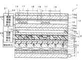
图4是根据本发明的显示设备的详细截面图;4 is a detailed cross-sectional view of a display device according to the present invention;
图5是显示设备的透视图;5 is a perspective view of a display device;
图6是根据本发明的第二个实施例的显示设备的截面图;6 is a cross-sectional view of a display device according to a second embodiment of the present invention;
图7是根据本发明的第三个实施例的显示设备的侧视图;7 is a side view of a display device according to a third embodiment of the present invention;
图8是根据本发明的第四个实施例的显示设备的侧视图;8 is a side view of a display device according to a fourth embodiment of the present invention;
图9是根据本发明的第五个实施例的显示设备的侧视图;9 is a side view of a display device according to a fifth embodiment of the present invention;
图10是根据本发明的第六个实施例的显示设备的截面图;10 is a cross-sectional view of a display device according to a sixth embodiment of the present invention;
图11是根据本发明的第七个实施例的显示设备的截面图;11 is a cross-sectional view of a display device according to a seventh embodiment of the present invention;
图12是根据本发明的第八个实施例的显示设备的截面图;12 is a cross-sectional view of a display device according to an eighth embodiment of the present invention;
图13是根据本发明的第九个实施例的显示设备的截面图;13 is a cross-sectional view of a display device according to a ninth embodiment of the present invention;
图14是根据本发明的第十个实施例的显示设备的侧视图;和14 is a side view of a display device according to a tenth embodiment of the present invention; and
图15是根据本发明的第十一个实施例的终端设备的透视图。Fig. 15 is a perspective view of a terminal device according to an eleventh embodiment of the present invention.
具体实施方式Detailed ways
之后将参照附图详细描述本发明的实施例。首先将描述本发明的第一个实施例。图3是根据本实施例的显示设备的示意性侧视图;图4是该显示设备的详细截面图;图5是该显示设备的透视图。Embodiments of the present invention will be described in detail later with reference to the accompanying drawings. First, a first embodiment of the present invention will be described. 3 is a schematic side view of a display device according to the present embodiment; FIG. 4 is a detailed sectional view of the display device; and FIG. 5 is a perspective view of the display device.
如图3中所示,在根据本实施例的显示设备1中,设置有平面光源2,用于向着显示设备1的前方,具体地说是向着观察者平面地发射光,并且设置有视角控制单元41,用于提高透射光的方向性。通过粘结层7将切换元件8结合到视角控制单元41的前表面。切换元件8在没有改变地透射入射光的透明状态与以散射方式透射入射光的半透明模糊状态之间进行切换。此外,在切换元件8的前面设置有显示面板42。显示面板42是通过透射从切换元件8发射的光来使图像与该光相关联的透射或半透射反射显示面板。显示设备1还设置有用于驱动切换元件8和显示面板42的驱动单元21。As shown in FIG. 3, in the
之后将进一步详细描述显示设备1的结构。如图4中所示,平面光源2设置有例如CCFL(冷阴极荧光灯),或其它冷阴极管3。冷阴极管3包括汞蒸气并通过从汞蒸气产生的紫外光激发磷光体来发射可见光。平面光源2还设置有光波导4。光波导4是由例如透明塑料组成的板形部件,其主表面的法线在前方向上。冷阴极管3布置于光波导4的侧面,从而光入射到光波导4的侧表面上。从侧表面入射的光通过光波导4以平面的方式从其前表面(光发射表面)发射出去。此外,光波导4的前面设置有两个棱镜片5。棱镜片5使从光波导4发射的光主要在向前的方向上传播。冷阴极管3、光波导4和棱镜片5组成了平面光源2。The structure of the
设置线性光栅片6作为视角控制单元41。在线性光栅片6中,在透明树脂片6a中彼此平行地嵌入用于吸收可见光的多个带状吸收部件6b,吸收部件6b的延伸方向和排列方向都与前方向正交。树脂片6a由吸收具有400nm或更小波长的光的材料形成,例如由聚萘二甲酸乙二醇酯(polyethylene naphthalate)(PEN)形成。由此可吸收从冷阴极管3泄漏的紫外光。线性光栅片6的厚度例如为0.1mm或更大。A linear grating sheet 6 is provided as the viewing
此外,在切换元件8中,彼此间隔开并彼此平行地设置有两个透明的塑料基板9a和9b,并在基板之间密封有聚合物分散型液晶层10。在聚合物分散型液晶层10中,在树脂10a中分散有液晶小滴10b。塑料基板9a和9b的相对表面设置有电极11a和11b。塑料基板9a结合到粘结层7。Furthermore, in the
还设置半透射反射液晶面板12作为显示面板42。设置框架形弹性树脂部件13,从而接触切换元件8的塑料基板9b,并通过弹性树脂部件13将切换元件8固定到半透射反射液晶面板12并支撑切换元件8。弹性树脂部件13由具有缓冲特性的材料形成,例如由硅树脂、弹性橡胶等形成。A transflective
在半透射反射液晶面板12中,彼此平行并间隔开地排列有由透明树脂构成的两个透明基板14a和14b,在透明基板之间设置有液晶层15。偏振板16a设置在外侧,具体地说是透明基板14a的后侧,并与弹性树脂部件13接触。偏振板16b设置在外侧,具体地说是透明基板14b的前侧,并且该偏振板组成了显示设备1的屏幕的最前面的表面。液晶层15的一侧的透明基板14a的表面设置有像素电极(图中没有示出),并且液晶层15的一侧的透明基板14b的表面设置有对向电极(图中没有示出)。由此在半透射反射液晶面板12的显示区域中以矩阵构造了多个单元。在每个单元中建立有反射区域17和透射区域18。在反射区域17中的透明基板14a和液晶层15之间设置反射部件19,凭借该反射部件,从前面进入并穿过液晶层15的光向前反射。In the transflective
驱动单元21还设置有液晶面板驱动单元22和切换元件驱动单元23。液晶面板驱动单元22给半透射反射液晶面板12馈送驱动信号并根据从外部输入的图像数据24在半透射反射液晶面板12中形成图像。切换元件驱动单元23通过给切换元件8的电极11a和11b施加电压而使切换元件8在透明状态和散射状态之间切换。例如,当切换元件驱动单元23不给电极11a和11b施加电压时,切换元件8处于透明状态中。当切换元件驱动单元23给电极11a和11b施加电压时,切换元件8处于散射状态。此时切换元件驱动单元23给电极11a和11b施加交流电压。The driving
当液晶面板驱动单元22驱动半透射反射液晶面板12的驱动频率为F1,并且通过切换元件驱动单元23施加给切换元件8的交流电压的频率是F2时,如此设定频率F2,使其比驱动半透射反射液晶面板12的频率F1高。具体地说,F2>F1。频率F2优选是F1的两倍或更高(F2=2×F1),并且频率F2更优选是频率F1的n倍,其中n是等于或大于2的整数。具体地说,优选F2=n×F1(其中n是等于或大于2的整数)。频率F1例如是60Hz,频率F2例如是240Hz。When the driving frequency of the transflective
如图5中所示,切换元件8和切换元件驱动单元23通过电缆25彼此相连。在显示设备1中,平面光源2中布置冷阴极管3的一侧与从切换元件8引出电缆25是同一侧。由此减小了显示表面周围包装外框(trim)的宽度。As shown in FIG. 5 , the switching
接下来将参照图3描述根据如上所述构造的本实施例的显示设备的工作。首先将描述窄角模式的工作。在窄角模式中,切换元件驱动单元23不给切换元件8的电极11a和11b施加电压。由此切换元件8处于透明状态中。平面光源2的冷阴极管3还向着光波导4发射光。此时,冷阴极管3内部的汞蒸气产生紫外线,这些紫外线激发磷光体,并输出可见光,但由汞蒸气产生的紫外线也与可见光混合并从冷阴极管3辐射出来。Next, the operation of the display device according to the present embodiment constructed as described above will be described with reference to FIG. 3 . First, the operation of the narrow-angle mode will be described. In the narrow-angle mode, the switching
从冷阴极管3发射的光从光波导4的侧表面进入光波导4,并从该侧表面平面地辐射。通过棱镜片5使光的主传播方向与前方向一致。然后,该光透过线性光栅片6,由此在从前方向明显倾斜的方向上传播的光被吸收部件6b吸收,并且只有在从前方向的特定范围倾斜角内的方向上传播的光透过树脂片6a。由此提高了光的方向性。通过树脂片6a吸收并阻挡了该光的紫外成分。The light emitted from the cold cathode tube 3 enters the optical waveguide 4 from the side surface of the optical waveguide 4, and is radiated planarly from the side surface. The main propagation direction of the light is made to coincide with the front direction by the prism sheet 5 . Then, the light is transmitted through the linear grating sheet 6, whereby light propagating in a direction significantly oblique from the front direction is absorbed by the absorbing member 6b, and only light propagating in a direction within a certain range of oblique angles from the front direction is transmitted through the resin Sheet 6a. As a result, the directivity of light is improved. The ultraviolet component of this light is absorbed and blocked by the resin sheet 6a.
从线性光栅片6发射的高方向性的光穿过粘结层7并进入切换元件8。因为切换元件8处于透明状态中,所以该光在仍旧保持高方向性的同时穿过切换元件8、进入半透射反射液晶面板12、穿过液晶层15、并在前方向上发射出来。Highly directional light emitted from the linear grating sheet 6 passes through the
从前面入射到半透射反射液晶面板12上的外部光透过液晶层15之后,该光被反射区域17中的反射部件19反射,再次透过液晶层15,并向着前方发射出去。External light incident on the transflective
在该状态中,液晶面板驱动单元22根据从外部输入的图像数据24驱动半透射反射液晶面板12。由此图像与从平面光源2发射的并透过半透射反射液晶面板12的透射区域18的光,以及从外部入射的并在反射区域17中反射的光相关。此时,因为从切换元件8发射的光具有高方向性,所以从半透射反射液晶面板12发射的光也具有高方向性,并在显示设备1的前方向上发射,但在倾斜方向上几乎没有光发射。由此仅仅向位于显示设备前面的观察者显示图像,并且能够阻止从斜向位置的偷窥。In this state, the liquid crystal panel driving unit 22 drives the transflective
接下来将描述宽角模式的工作。在宽角模式中,切换元件驱动单元23给切换元件8的电极11a和11b施加具有频率F2的交流电压。由此切换元件8处于散射状态中。在该状态中,冷阴极管3发射光,并且液晶面板驱动单元22根据图像数据24驱动半透射反射液晶面板12。如上所述,该频率F2高于半透射反射液晶面板12的驱动频率F1,例如是频率F1的两倍或更高,或者例如是频率F1的n倍(其中n是等于或大于2的整数)。例如频率F1是60Hz,例如频率F2是240Hz。Next, the operation of the wide-angle mode will be described. In the wide-angle mode, the switching
在宽角模式中,在从冷阴极管3发射的光穿过粘结层7之前的工作与窄角模式中相同。从在散射状态中,具体地说在低方向性的状态中的切换元件8发射的光入射到半透射反射液晶面板12,并透过透射区域18,之后光向着前方输出。此时,从半透射反射液晶面板12输出的光具有低方向性,并在显示设备1的前方向上以及倾斜方向上发射。由此可以给位于显示设备前方的观察者和斜向位置中的观察者显示图像。In the wide-angle mode, the operation before the light emitted from the cold-cathode tube 3 passes through the
之后将描述本发明的构造条件中限制数值的原因。The reasons for restricting numerical values in the configuration conditions of the present invention will be described later.
(a)切换元件的驱动频率F2:高于液晶面板的驱动频率F1(F2>F1)(a) The driving frequency F2 of the switching element: higher than the driving frequency F1 of the liquid crystal panel (F2>F1)
如上所述,切换元件8中总是包含离子杂质,并且其数量随时间而增加。由此聚合物分散液晶层10的电阻随时间降低。当切换元件8中存在离子杂质,并且给切换元件施加总是完美对称的正负交流电压时,离子杂质不会不均匀地分布在电极之一的一侧,并且切换元件表现出相同的光学响应,不管是给切换元件施加正电压还是负电压。然而,实际应用中很难给切换元件施加完全没有直流分量的正负交流电压。因此由于施加电压中的直流分量,切换元件中的离子杂质逐渐地更加集中在一侧电极附近。因为离子杂质变为不均匀地分布,所以切换元件在施加负电压期间和施加正电压期间表现出不同的光学响应,且透射率开始变化。过去,因为通过具有与液晶面板相同频率的正负交流电压来驱动切换元件,所以上述光学响应的不对称作为闪烁被观察者识别到。As described above, ion impurities are always contained in the
相反,当切换元件的驱动频率F2比液晶面板的驱动频率F1大时,切换元件的光学响应中的不对称不易被观察者识别到,即使当切换元件恶化和离子杂质增加且变为不均匀地分布时。因此,在本发明中将切换元件的驱动频率F2设为高于液晶面板的驱动频率F1。频率F2优选高于60Hz。On the contrary, when the driving frequency F2 of the switching element is greater than the driving frequency F1 of the liquid crystal panel, the asymmetry in the optical response of the switching element is not easily recognized by the observer, even when the switching element deteriorates and ion impurities increase and become uneven When distributing. Therefore, in the present invention, the driving frequency F2 of the switching element is set higher than the driving frequency F1 of the liquid crystal panel. The frequency F2 is preferably higher than 60 Hz.
(b)切换元件的驱动频率F2:是液晶面板的驱动频率F1的两倍或更高(F2=2×F1)(b) Driving frequency F2 of the switching element: twice or more than the driving frequency F1 of the liquid crystal panel (F2=2×F1)
本显示设备的透射率可以表示为切换元件的透射率和显示面板的透射率的乘积。如前面所提到的,切换元件的透射率能够根据正电压和负电压而变化。显示面板通过以特定驱动频率刷新屏幕来显示图像。因此,当显示面板的驱动频率(F1)和切换元件的驱动频率(F2)不同时,显示设备的总透射率在频率的和(F1+F2)与频率的差(F2-F1)的绝对值之间波动。因为频率的和(F1+F2)是高于频率F1的频率,所以观察者识别不到该波动。另一方面,频率的差(F2-F1)的绝对值是低的频率,如果该值到达一定水平,就会存在观察者注意到闪烁的危险。The transmittance of the present display device can be expressed as the product of the transmittance of the switching element and the transmittance of the display panel. As mentioned previously, the transmittance of the switching element can vary according to positive and negative voltages. The display panel displays images by refreshing the screen at a specific driving frequency. Therefore, when the driving frequency (F1) of the display panel and the driving frequency (F2) of the switching element are different, the total transmittance of the display device is in the absolute value of the frequency sum (F1+F2) and the frequency difference (F2-F1) fluctuate between. Since the sum of frequencies (F1+F2) is a frequency higher than the frequency F1, the observer cannot recognize this fluctuation. On the other hand, the absolute value of the frequency difference (F2-F1) is a low frequency, and if the value reaches a certain level, there is a danger that the observer will notice flicker.
因此,当频率F2是频率F1的两倍或更高时,显示的波动频率(F2-F1的绝对值)变为F1或更高,不再看到闪烁。由此可以在没有不舒适的情况下观察图像,即使当发生显示波动时。因此,切换元件的驱动频率F2优选是液晶面板的驱动频率F1的两倍或更高。Therefore, when the frequency F2 is twice or higher than the frequency F1, the displayed fluctuating frequency (the absolute value of F2-F1) becomes F1 or higher, and flickering is no longer seen. It is thereby possible to observe images without discomfort even when display fluctuations occur. Therefore, the driving frequency F2 of the switching element is preferably twice or higher than the driving frequency F1 of the liquid crystal panel.
(c)切换元件的驱动频率F2:是液晶面板的驱动频率F1的n倍(其中n是等于或大于2的整数)(F2=n×F1)(c) The driving frequency F2 of the switching element: n times the driving frequency F1 of the liquid crystal panel (where n is an integer equal to or greater than 2) (F2=n×F1)
当频率F2是频率F1的n倍时,频率(F2-F1)的绝对值变为频率F1的整数倍。由此图像的透射率变化的频率变为图像的内容变化的频率的整数倍,并且可更进一步减小由观察者感受到的不舒适。因此,切换元件的驱动频率F2优选是液晶面板的驱动频率F1的n倍(其中n是等于或大于2的整数)。When the frequency F2 is n times the frequency F1, the absolute value of the frequency (F2-F1) becomes an integer multiple of the frequency F1. The frequency at which the transmittance of the image changes thereby becomes an integer multiple of the frequency at which the content of the image changes, and the discomfort felt by the observer can be further reduced. Therefore, the driving frequency F2 of the switching element is preferably n times (where n is an integer equal to or greater than 2) the driving frequency F1 of the liquid crystal panel.
接下来将描述本实施例的效果。根据本实施例,因为显示的视角能够在窄角和宽角之间切换,所以可在窄角模式中防止偷窥,并在宽角模式中使多个用户同时观看所有图像。Next, effects of the present embodiment will be described. According to the present embodiment, since the displayed viewing angle can be switched between a narrow angle and a wide angle, it is possible to prevent peeping in the narrow angle mode and allow multiple users to view all images simultaneously in the wide angle mode.
根据上述原理本实施例能够防止闪烁。The present embodiment can prevent flickering based on the above principle.
此外,在本实施例中,因为塑料基板9a和9b是切换元件8的基板,并且半透射反射液晶面板12的透明基板14a和14b由树脂形成,所以能够减小显示设备1的厚度和重量,并能够提高其机械耐久性。Furthermore, in this embodiment, since the plastic substrates 9a and 9b are the substrates of the
然而,由塑料形成切换元件8的基板产生了几个问题。因此,在本实施例中采取了措施来克服这些问题。之后将描述将塑料基板用于切换元件8的基板而产生的问题,以及克服这些问题采取的措施。However, forming the substrate of the
液晶通常被紫外辐射退化。然而,在用于图像显示的公共液晶面板中,将偏振板粘贴到透明基板的两侧,并且该偏振板用作有效的紫外阻挡部件。因此液晶没有暴露于恶劣的紫外辐射的环境中。然而在本实施例中,散射型液晶布置在光源和显示面板之间。因此,在冷阴极管中用于激发磷光体的一部分紫外光直接入射到散射型液晶部件上,导致液晶的紫外退化。尤其在本实施例中,切换元件中包含的聚合物分散型液晶层是散射型液晶,因此其通过紫外曝光来制造。因此在切换元件的塑料基板中使用能透射紫外线的基板。因而如果在冷阴极管和切换元件之间没有布置用于吸收紫外线的部件,则通过紫外线就退化聚合物分散型液晶层中的液晶小滴。即使当在切换元件中使用宾主液晶时也发生同样问题。在该情形中,除了液晶部件的退化之外还发生了二色性燃料部件的退化。Liquid crystals are generally degraded by ultraviolet radiation. However, in a common liquid crystal panel for image display, a polarizing plate is pasted to both sides of a transparent substrate, and the polarizing plate serves as an effective ultraviolet blocking member. Therefore, the liquid crystal is not exposed to the environment of harsh ultraviolet radiation. However, in this embodiment, the scattering type liquid crystal is arranged between the light source and the display panel. Therefore, part of the ultraviolet light used to excite the phosphor in the cold cathode tube is directly incident on the scattering type liquid crystal part, causing ultraviolet degradation of the liquid crystal. Especially in this embodiment, the polymer-dispersed liquid crystal layer contained in the switching element is a scattering liquid crystal, and thus it is produced by ultraviolet exposure. Therefore, a UV-transmissive substrate is used in the plastic substrate of the switching element. Thus, if no means for absorbing ultraviolet rays is arranged between the cold cathode tube and the switching element, the liquid crystal droplets in the polymer-dispersed liquid crystal layer are degraded by the ultraviolet rays. The same problem occurs even when guest-host liquid crystals are used in the switching element. In this case, degradation of the dichroic fuel component occurred in addition to degradation of the liquid crystal component.
为了克服该问题,本实施例中线性光栅片6的树脂片6a由吸收紫外线的材料形成。因此从冷阴极管3发射的紫外线被线性光栅片6阻挡。由此防止了切换元件8暴露于紫外线,并且切换元件8的液晶小滴10b不会被紫外线退化。In order to overcome this problem, the resin sheet 6a of the linear grating sheet 6 in this embodiment is formed of a material that absorbs ultraviolet rays. Ultraviolet rays emitted from the cold cathode tube 3 are thus blocked by the linear grating sheet 6 . Exposure of the
与玻璃相比,塑料还具有较高的湿气渗透性。因此当切换元件的基板由塑料形成时,不可能确保内部液晶的长期工作。当在液晶面板中使用塑料基板时,塑料基板的内表面通常涂敷有用于提高防止湿气性的氧化硅膜等。然而,在该情形中必需在塑料基板的内表面上形成包含氧化硅膜和透明电极层的两层或多层。因而由多层结构确保的可靠性需要昂贵的塑料基板。Plastic also has a higher moisture vapor permeability compared to glass. It is therefore impossible to ensure long-term operation of the internal liquid crystal when the substrate of the switching element is formed of plastic. When a plastic substrate is used in a liquid crystal panel, the inner surface of the plastic substrate is usually coated with a silicon oxide film or the like for improving moisture resistance. In this case, however, it is necessary to form two or more layers including a silicon oxide film and a transparent electrode layer on the inner surface of the plastic substrate. The reliability ensured by the multilayer structure thus requires expensive plastic substrates.
因此,在本实施例中,切换元件8的塑料基板9a的整个表面通过粘结层7结合到线性光栅片6。因而切换元件8的后表面侧的塑料基板的有效厚度增加,可防止湿气从后表面侧渗入。由此仅对前表面侧的塑料基板涂布湿气阻挡涂层就足够了,不再需要给后表面侧的塑料基板涂布湿气阻挡涂层。因此确保了可靠性,同时保持了低成本。尤其是在本实施例中,因为线性光栅片6的厚度是0.1mm或更大,所以可获得充分的湿气阻挡能力。结果,可抑制切换元件随时间的恶化,并提高显示设备的可靠性。Therefore, in the present embodiment, the entire surface of the plastic substrate 9 a of the
另一个问题是散射型液晶易受机械冲击的影响。如上所述,公知的散射型液晶包括聚合物分散液晶、聚合物网状液晶、胶囊型液晶等。这些类型的液晶共有的结构是具有液晶相和树脂相的结构。由此通过液晶相和树脂相的折射率非排列/排列可获得散射/透明切换。这些相中的树脂相具有固定的结构,因此尤其容易受到机械冲击,并且一旦被破坏就不能恢复。散射型液晶通常具有大约几微米或更小的厚度。该极薄的固体树脂层必须保持机械稳定。然而,当在塑料基板之间布置树脂层时会发生机械问题。塑料基板容易因为外力等而扭曲,弯曲和其它变形。因此与在玻璃基板之间布置散射型液晶部件的情形相比,该组件更容易受到损坏。尽管在宾主液晶部件的情形中在内部没有固定的结构,如树脂相,但在塑料基板容易变形的情形中仍会发生不均匀的显示。具体地说,当塑料基板弯曲时出现了不均匀显示的问题,并且在宾主液晶部件中产生厚部和薄部。因为通常在移动或便携式终端设备中使用具有可切换视角的显示设备,所以必须考虑由于掉落或在使用过程中冲击的可能性,并且易于受到机械冲击成为问题。Another problem is that scattering liquid crystals are susceptible to mechanical shock. As described above, known scattering type liquid crystals include polymer dispersed liquid crystals, polymer network liquid crystals, capsule type liquid crystals, and the like. A structure common to these types of liquid crystals is a structure having a liquid crystal phase and a resin phase. Scattering/transparency switching can thus be obtained by non-alignment/alignment of the refractive indices of the liquid crystal phase and the resin phase. The resinous phase of these phases has a fixed structure and is therefore particularly vulnerable to mechanical shock and cannot recover once damaged. Scattering liquid crystals generally have a thickness of about several micrometers or less. This extremely thin layer of solid resin must remain mechanically stable. However, mechanical problems occur when resin layers are arranged between plastic substrates. Plastic substrates are prone to twisting, bending and other deformations due to external forces and the like. The assembly is therefore more susceptible to damage than in the case of arranging a scattering type liquid crystal component between glass substrates. Although there is no fixed structure inside such as a resin phase in the case of a guest-host liquid crystal component, uneven display occurs in the case where the plastic substrate is easily deformed. Specifically, a problem of uneven display occurs when the plastic substrate is bent, and thick and thin portions are generated in the guest-host liquid crystal component. Since display devices with switchable viewing angles are generally used in mobile or portable terminal devices, the possibility of shock due to dropping or during use must be considered, and susceptibility to mechanical shock becomes a problem.
因此,在本实施例中,切换元件8通过弹性树脂部件13固定到半透射反射液晶面板12。由此可以保护切换元件8免受机械应力。Therefore, in the present embodiment, the switching
接下来将描述本发明的第二个实施例。图6是根据本实施例的显示设备的截面图。如图6中所示,在根据本实施例的显示设备31中的棱镜片5和线性光栅片6之间布置有漫射板32。漫射板32由树脂材料(例如聚萘二甲酸乙二醇酯(PEN))形成。该漫射板透射可见光并吸收具有400nm或更小波长的光。由此可吸收从冷阴极管3泄漏的紫外光。在本实施例中,线性光栅片6的树脂片6a可以以与前面所述的第一个实施例中相同的方式由吸收紫外线的材料形成,或可以由不吸收紫外线的材料形成。Next, a second embodiment of the present invention will be described. FIG. 6 is a sectional view of the display device according to the present embodiment. As shown in FIG. 6 , a diffusion plate 32 is arranged between the prism sheet 5 and the linear lenticular sheet 6 in the display device 31 according to the present embodiment. The diffusion plate 32 is formed of a resin material such as polyethylene naphthalate (PEN). The diffusion plate transmits visible light and absorbs light having a wavelength of 400 nm or less. Thereby, ultraviolet light leaked from the cold cathode tube 3 can be absorbed. In this embodiment, the resin sheet 6a of the linear grating sheet 6 may be formed of a material that absorbs ultraviolet rays in the same manner as in the first embodiment described above, or may be formed of a material that does not absorb ultraviolet rays.
显示设备31还设置有用于容纳平面光源2的框架33、漫射板32、线性光栅片6、切换元件8和弹性树脂部件13。通过将前框架33b装配到后框架33a中,将框架33形成为框架形。框架33覆盖了平面光源2的后表面的外围以及平面光源2、漫射板32、线性光栅片6、切换元件8和弹性树脂部件13的侧表面。前框架33b覆盖切换元件8和弹性树脂部件13的侧表面及前表面的外围。切换元件8的前表面通过弹性树脂部件13粘结并固定到前框架33b。The display device 31 is also provided with a
此外,代替前述第一个实施例中的粘结层7,显示设备31设置有弹性树脂部件36。具体地说,在线性光栅片6和切换元件8之间布置弹性树脂部件36。由此切换元件8通过弹性树脂部件36固定到线性光栅片6。Furthermore, the display device 31 is provided with an elastic resin member 36 instead of the
代替前述第一个实施例中的半透射反射液晶面板12,显示设备31设置有透射液晶面板34。The display device 31 is provided with a transmissive liquid crystal panel 34 instead of the transflective
代替前述第一个实施例中的切换元件驱动单元23,显示设备31还设置有切换元件驱动单元35。切换元件驱动单元35从透射液晶面板34接收驱动同步信号,产生具有四倍于驱动同步信号频率的频率的信号,并根据该信号给切换元件8供给驱动电压。因此,如果透射液晶面板34例如以60Hz的频率被驱动,则切换元件8与透射液晶面板34同步并以240Hz的频率被驱动。除了上面描述的那些之外,本实施例中的构造的各方面与前述第一个实施例中的相同。The display device 31 is further provided with a switching element driving unit 35 instead of the switching
接下来将描述本实施例的工作和效果。有时根据显示面板设定复位周期。在这种情形中,如果切换元件和显示面板的驱动时序不同步,那么即使当切换元件的驱动频率F2是显示面板的驱动频率F1的多倍时,显示设备的透射率也在施加正电位的帧与施加负电位的帧之间变化。相反,在本实施例中通过将切换元件的驱动时序与显示面板的驱动时序同步,可防止透射率在施加正电位的帧与施加负电位的帧之间变化。由此可更可靠地防止闪烁的发生。Next, the operation and effects of this embodiment will be described. Sometimes the reset period is set according to the display panel. In this case, if the driving timing of the switching element and the display panel are not synchronized, even when the driving frequency F2 of the switching element is a multiple of the driving frequency F1 of the display panel, the transmittance of the display device is at the level of applying a positive potential. The frame changes from the frame to which the negative potential is applied. On the contrary, by synchronizing the driving timing of the switching element with the driving timing of the display panel in this embodiment, it is possible to prevent the transmittance from changing between a frame in which a positive potential is applied and a frame in which a negative potential is applied. Thereby, occurrence of flicker can be more reliably prevented.
在本实施例中,切换元件8通过弹性树脂部件13固定到框架33的前框架33b,并通过弹性树脂部件36固定到线性光栅片6。具体地说,通过弹性树脂部件13和36来支撑切换元件8。由此可阻止切换元件8免受机械应力,并且还提高了切换元件的后表面侧的湿气阻止特性。结果,可提高显示设备31的可靠性,而不增加其组件数量。除了上面所述的那些之外,本实施例中的效果和工作方面与前述第一个实施例中的相同。In the present embodiment, the switching
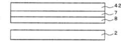
接下来将描述本发明的第三个实施例。图7是根据本实施例的显示设备的侧视图。在图7中,为了简化附图,省略掉了驱动单元。对于之后描述的图8到15也同样如此。如图7中所示,在本实施例中没有设置视角控制单元41(见图3),并且平面光源2通过粘结层7结合到切换元件8的后表面侧的塑料基板(图中没有示出)。因而增加了切换元件8的后表面侧的塑料基板的有效厚度,并可以防止湿气从后表面侧渗入。该显示设备还设置有显示面板42。显示面板42可以与前面所述的第一个实施例中的半透射反射液晶面板12相同,或可以与前面所述的第二个实施例中的透射液晶面板34相同,或可以是除了液晶面板之外的其他透射型显示面板。除上面所述的那些之外,本实施例中的结构和工作的各效果和方面与前面所述的第一个实施例中的相同。Next, a third embodiment of the present invention will be described. FIG. 7 is a side view of the display device according to the present embodiment. In FIG. 7, in order to simplify the drawing, the driving unit is omitted. The same is true for FIGS. 8 to 15 described later. As shown in FIG. 7 , in this embodiment, the viewing angle control unit 41 (see FIG. 3 ) is not provided, and the planar
接下来将描述本发明的第四个实施例。图8是根据本实施例的显示设备的侧视图。如图8中所示,本实施例中的粘结层7设置在切换元件8的前表面侧,而不是后表面侧。由此切换元件8的前表面侧的塑料基板的整个表面通过粘结层7结合到显示面板42的后表面。因而增加了切换元件8的前表面侧的塑料基板的有效厚度,并可以防止湿气从前表面侧渗入。除上面所述的那些之外,本实施例中的结构和工作的各效果和方面与前面所述的第一个实施例中的相同。Next, a fourth embodiment of the present invention will be described. FIG. 8 is a side view of the display device according to the present embodiment. As shown in FIG. 8 , the
在本实施例中,当显示面板42是在其前表面侧和后表面侧设置有偏振板的液晶面板,并且切换元件8通过粘结层7结合到后表面侧的偏振板时,后表面侧的偏振板的厚度优选为0.1mm或更大。由此可充分防止湿气从切换元件8的前表面侧渗入。In the present embodiment, when the
接下来将描述本发明的第五个实施例。图9是根据本实施例的显示设备的侧视图。如图9中所示,本实施例中没有设置视角控制单元41(见图3),并且替代地将紫外吸收片43设置在冷阴极管3和切换元件8之间。紫外吸收片43例如由聚耐二甲酸乙二醇酯(PEN)形成。因而可通过紫外吸收片43阻挡从平面光源2的冷阴极管发射的紫外线,可保护切换元件8免受紫外线损伤。结果,能够防止由紫外线导致的切换元件8的恶化,可确保显示设备的可靠性。除上面所述的那些之外,本实施例中的结构和工作的各效果和方面与前面所述的第一个实施例中的相同。紫外吸收片43还可结合到切换元件8。由此可赋予紫外吸收片43紫外阻挡能力以及湿气阻挡能力。Next, a fifth embodiment of the present invention will be described. FIG. 9 is a side view of the display device according to the present embodiment. As shown in FIG. 9 , the viewing angle control unit 41 (see FIG. 3 ) is not provided in this embodiment, and an ultraviolet absorbing sheet 43 is provided between the cold cathode tube 3 and the
接下来将描述本发明的第六个实施例。图10是根据本实施例的显示设备的截面图。如图10中所示,本实施例与前述第二个实施例不同在于,省略掉了前框架,在切换元件8的后表面侧的整个表面上布置有弹性树脂部件44,并且切换元件8通过该弹性树脂部件44固定到平面光源2。因为弹性树脂部件44吸收机械冲击,所以没有大的外力施加到切换元件8上,并且可防止切换元件8中的树脂10a(见图4)破裂。根据温度变化而发生在切换元件8和后框架33a之间的膨胀和收缩,以及发生在切换元件8和平面光源2之间的膨胀和收缩也被弹性树脂部件13吸收。因此,即使当温度变化时,切换元件也不会受到热应力,并且能够防止切换元件断裂。除上面所述的那些之外,本实施例中的结构和工作的各效果和方面与前面所述的第二个实施例中的相同。Next, a sixth embodiment of the present invention will be described. FIG. 10 is a sectional view of the display device according to the present embodiment. As shown in FIG. 10, this embodiment differs from the foregoing second embodiment in that the front frame is omitted, an
接下来将描述本发明的第七个实施例。图11是根据本实施例的显示设备的截面图。如图11中所示,本实施例与前面所述的第六个实施例的区别在于,仅给切换元件8的后表面的外围部分设置弹性树脂部件44。除上面所述的那些之外,本实施例中的结构和工作的各效果和方面与前面所述的第六个实施例中的相同。Next, a seventh embodiment of the present invention will be described. FIG. 11 is a sectional view of the display device according to the present embodiment. As shown in FIG. 11, this embodiment differs from the aforementioned sixth embodiment in that an
接下来将描述本发明的第八个实施例。图12是根据本实施例的显示设备的截面图。如图12中所示,在本实施例中,视角控制单元41和切换元件8通过粘结层7彼此粘附,并且得到的结合体通过弹性树脂部件45固定到平面光源2。由此通过弹性树脂部件45来支撑视角控制单元41和切换元件8之间的结合体。结果,获得了具有出色耐湿气性和耐机械冲击以及热膨胀的显示设备。Next, an eighth embodiment of the present invention will be described. FIG. 12 is a sectional view of the display device according to the present embodiment. As shown in FIG. 12 , in the present embodiment, viewing
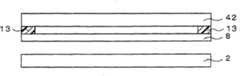
接下来将描述本发明的第九个实施例。图13是根据本实施例的显示设备的截面图。如图13中所示,在本实施例中,切换元件8通过弹性树脂部件13固定到显示面板42。弹性树脂部件13以框架形状设置在显示面板42的后表面侧的外围上。除上面所述的那些之外,本实施例中的结构和工作的各效果和方面与前面所述的第一个实施例中的相同。Next, a ninth embodiment of the present invention will be described. FIG. 13 is a sectional view of the display device according to the present embodiment. As shown in FIG. 13 , in the present embodiment, the switching
接下来将描述本发明的第十个实施例。图14是根据本实施例的显示设备的侧视图。如图14中所示,在本实施例中,切换元件8通过弹性树脂部件46固定到显示面板42。弹性树脂部件46设置在显示面板42的后表面侧的整个表面上。除上面所述的那些之外,本实施例中的结构和工作的各效果和方面与前面所述的第一个实施例中的相同。Next, a tenth embodiment of the present invention will be described. FIG. 14 is a side view of the display device according to the present embodiment. As shown in FIG. 14 , in the present embodiment, the switching
在上面所述的实施例中光波导可以被赋予紫外吸收能力。前面的实施例中描述了侧光型光源用作平面光源的例子,但本发明并不限于该构造,而是也可以使用底光型光源。底光型光源由多个光源元件和布置在光源元件之上用于产生均匀亮度的漫射片组成。当使用底光型光源时,漫射片可以被赋予紫外吸收能力。在任何情形中,通过给平面光源的一部分提供紫外吸收能力,可免除独立的紫外吸收层,并能够防止切换元件的恶化,而不增加组件的数量。In the embodiments described above the optical waveguide may be endowed with UV absorbing capabilities. In the foregoing embodiments, an example in which a side-light type light source is used as a planar light source has been described, but the present invention is not limited to this configuration, but a bottom-light type light source may also be used. The backlight type light source is composed of a plurality of light source elements and a diffuser arranged over the light source elements for uniform brightness. When using backlit light sources, the diffuser can be rendered UV absorbing. In any case, by providing ultraviolet absorbing ability to a part of the planar light source, a separate ultraviolet absorbing layer can be dispensed with, and deterioration of the switching element can be prevented without increasing the number of components.
还可给用于提高平面光源的方向性的棱镜片提供紫外吸收能力。通过选择组成材料或通过将紫外吸收物质混合进组成材料中可获得该能力。由此能够确保可靠性而不进一步增加组件的数量。It is also possible to provide ultraviolet absorbing ability to a prism sheet for improving the directivity of a planar light source. This capability can be obtained by choice of constituent materials or by mixing UV-absorbing substances into the constituent materials. Reliability can thereby be ensured without further increasing the number of components.
在前述实施例中还描述了散射型液晶元件用作切换元件的例子,其中当不施加电压时切换元件处于透明状态,而当施加电压时其处于散射状态。然而,本发明并不限于该构造,并且可以使用当不施加电压时处于散射状态,而当施加电压时处于透明状态的散射型液晶元件。还可以使用设置有具有细长形状的二色性燃料分子的宾主液晶元件作为切换元件。Also described in the foregoing embodiments is an example in which a scattering type liquid crystal element is used as a switching element in which the switching element is in a transparent state when no voltage is applied and is in a scattering state when a voltage is applied. However, the present invention is not limited to this configuration, and a scattering type liquid crystal element that is in a scattering state when no voltage is applied and is in a transparent state when a voltage is applied may be used. It is also possible to use a guest-host liquid crystal element provided with dichroic fuel molecules having an elongated shape as a switching element.
此外,在前面所述的实施例中粘结层或弹性树脂部件的厚度优选为10微米或更大。由此由面内光学干涉导致的条纹线几乎不引人注意。例如,在图12中所示的第八个实施例中,通过将弹性树脂部件45的厚度设到10微米或更大,可抑制由于平面光源2的前表面与视角控制单元41的后表面之间的干涉而产生条纹线。通过使粘结层7为10微米或更大的厚度可获得相同的效果。例如,在图12中,通过使粘结层7为10微米或更大的厚度,可抑制视角控制单元41的前表面与切换元件8的后表面之间的光学干涉。Furthermore, the thickness of the adhesive layer or the elastic resin member in the foregoing embodiments is preferably 10 microns or more. Streak lines resulting from in-plane optical interference are thus hardly noticeable. For example, in the eighth embodiment shown in FIG. 12, by setting the thickness of the
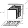
接下来将描述本发明的第十一个实施例。本实施例是根据本发明的终端设备的实施例。图15是根据本实施例的终端设备的透视图。如图15中所示,根据本实施例的终端设备是笔记本型个人计算机(笔记本PC)51。在该笔记本PC 51中设置有操作单元52和可旋转地连接到该操作单元52的边缘的显示单元53,并且具有可切换视角的显示设备1嵌入到显示单元53中。该显示设备1与根据前面所述的第一个实施例的显示设备1(见图3到图5)相同。显示设备1中线性光栅片6的吸收部件6b(见图4)的延伸方向与垂直于笔记本PC 51的屏幕的方向54基本一致。本实施例的工作和效果与前面所述的第一个实施例中的相同。Next, an eleventh embodiment of the present invention will be described. This embodiment is an embodiment of a terminal device according to the present invention. Fig. 15 is a perspective view of a terminal device according to the present embodiment. As shown in FIG. 15 , the terminal device according to the present embodiment is a notebook-type personal computer (notebook PC) 51 . In this
当考虑由线性光栅片与显示面板之间的干涉导致的莫尔波纹时,吸收部件6b的延伸方向可从垂直于屏幕的方向54倾斜10度或更小的角度。由此可减少莫尔波纹。还可通过在线性光栅片6与切换元件8之间进一步设置漫射片来消除莫尔波纹。还可将根据前面所述的第二个到第十个实施例的任意一个的显示设备结合进笔记本PC 51的显示单元53中。尤其当本实施例的终端设备是移动/便携型终端设备时,户外使用是常见的,并且希望具有出色可靠性的设备。通过将根据前面所述的第一个到第十个实施例的显示设备应用于这种终端设备,可获得满足前述要求的终端设备。When considering moiré caused by interference between the linear lenticular sheet and the display panel, the extending direction of the absorbing member 6b may be inclined at an angle of 10 degrees or less from the
本实施例中描述了终端设备是笔记本型个人计算机的例子,但本发明并不限于该构造,而是还可以应用于移动电话、PDA等。An example in which the terminal device is a notebook type personal computer has been described in this embodiment, but the present invention is not limited to this configuration, but can also be applied to mobile phones, PDAs, and the like.
Claims (22)
Translated fromChineseApplications Claiming Priority (2)
| Application Number | Priority Date | Filing Date | Title |
|---|---|---|---|
| JP2005144746 | 2005-05-17 | ||
| JP2005144746AJP2006323031A (en) | 2005-05-17 | 2005-05-17 | Viewing angle switching display device and terminal device |
Publications (2)
| Publication Number | Publication Date |
|---|---|
| CN1866084A CN1866084A (en) | 2006-11-22 |
| CN100458506Ctrue CN100458506C (en) | 2009-02-04 |
Family
ID=37425146
Family Applications (1)
| Application Number | Title | Priority Date | Filing Date |
|---|---|---|---|
| CNB2006100818025AActiveCN100458506C (en) | 2005-05-17 | 2006-05-16 | Display device with switchable viewing angle, and terminal device |
Country Status (3)
| Country | Link |
|---|---|
| US (1) | US20060262057A1 (en) |
| JP (1) | JP2006323031A (en) |
| CN (1) | CN100458506C (en) |
Families Citing this family (39)
| Publication number | Priority date | Publication date | Assignee | Title |
|---|---|---|---|---|
| US7349043B2 (en)* | 2004-05-24 | 2008-03-25 | Nec Corporation | Light source, display device, portable terminal device, and ray direction switching element |
| JP4831729B2 (en)* | 2005-08-05 | 2011-12-07 | Nltテクノロジー株式会社 | Variable viewing angle liquid crystal display device, method and terminal |
| US7973749B2 (en)* | 2006-01-31 | 2011-07-05 | Nec Lcd Technologies, Ltd. | Display device, terminal device, and display panel |
| JP2008046387A (en)* | 2006-08-17 | 2008-02-28 | Nec Saitama Ltd | Information processor |
| US20080107830A1 (en)* | 2006-11-03 | 2008-05-08 | Motorola, Inc. | Image-providing apparatus and method for communication device |
| KR101435697B1 (en) | 2006-11-30 | 2014-09-01 | 히다찌 겐끼 가부시키가이샤 | Speed change control system for industrial vehicle |
| KR101393627B1 (en)* | 2007-03-02 | 2014-05-12 | 삼성디스플레이 주식회사 | Display device and control method of the same |
| WO2008114678A1 (en)* | 2007-03-16 | 2008-09-25 | Sharp Kabushiki Kaisha | Viewing angle control device and display provided with the same |
| FR2915332B1 (en)* | 2007-04-17 | 2009-07-10 | Parrot Sa | HANDS-FREE SELF-CONTAINED TELEPHONE ADAPTER IN THE CIGAR LIGHTER SOCKET OF A MOTOR VEHICLE |
| KR101352906B1 (en)* | 2007-07-13 | 2014-01-20 | 엘지디스플레이 주식회사 | Liquide crystal display device and method for fabricating the same |
| JP5631739B2 (en)* | 2007-11-29 | 2014-11-26 | コーニンクレッカ フィリップス エヌ ヴェ | Method and device for providing privacy to a display |
| JP5028342B2 (en)* | 2008-06-19 | 2012-09-19 | 一般財団法人川村理化学研究所 | Organic-inorganic composite including liquid crystal compound |
| US8608337B2 (en)* | 2010-02-18 | 2013-12-17 | Koninklijke Philips N.V. | Lighting fixture having a louvered light shield |
| WO2011113180A1 (en) | 2010-03-19 | 2011-09-22 | Nokia Corporation | Apparatus, methods and computer programs for configuring output of a display |
| JP5692519B2 (en)* | 2010-06-21 | 2015-04-01 | Nltテクノロジー株式会社 | Image display device, electronic apparatus using the same, display output control method for image display device, and output control program thereof |
| JP5801602B2 (en)* | 2011-05-12 | 2015-10-28 | ピクストロニクス,インコーポレイテッド | Image display device |
| CN102866526B (en)* | 2012-09-21 | 2016-08-03 | 京东方科技集团股份有限公司 | Display device |
| JP2014071372A (en)* | 2012-09-28 | 2014-04-21 | Japan Display Inc | Display device and electronic equipment |
| JP2014102295A (en)* | 2012-11-16 | 2014-06-05 | Sony Corp | Display device, display method and recording medium |
| CN103309144A (en)* | 2013-05-07 | 2013-09-18 | 大连摩尔登科技股份有限公司 | Semitransparent liquid crystal screen with light source |
| CN106461997A (en) | 2014-05-30 | 2017-02-22 | 3M创新有限公司 | Variable viewing angle optical systems |
| KR102314403B1 (en)* | 2014-11-14 | 2021-10-19 | 삼성디스플레이 주식회사 | Display device and method for manufacturing thereof |
| CN105549236B (en) | 2016-02-19 | 2020-05-12 | 京东方科技集团股份有限公司 | Switchable peep-proof device, preparation method thereof and display device |
| WO2018022098A1 (en)* | 2016-07-29 | 2018-02-01 | Hewlett-Packard Development Company, L.P. | Display control in display devices |
| US10809551B2 (en) | 2016-08-08 | 2020-10-20 | Infovision Optoelectronics (Kunshan) Co., Ltd. | Liquid crystal display device having switchable viewing angles and viewing angle switching method thereof |
| WO2018049559A1 (en)* | 2016-09-13 | 2018-03-22 | 昆山龙腾光电有限公司 | Liquid crystal display device with switchable viewing angle, and viewing angle switching method |
| CN106842737A (en)* | 2017-03-30 | 2017-06-13 | 惠科股份有限公司 | Liquid crystal display and method for improving viewing angle color difference thereof |
| TW201839470A (en)* | 2017-04-21 | 2018-11-01 | 昶曜科技股份有限公司 新北市新莊區中正路542號之16 3樓 | Active anti-peeping device |
| US10852598B2 (en)* | 2017-09-06 | 2020-12-01 | Sony Corporation | Optical device, display device, and electronic apparatus |
| CN108957841A (en)* | 2018-08-29 | 2018-12-07 | 京东方科技集团股份有限公司 | Display device |
| KR102279480B1 (en)* | 2019-12-18 | 2021-07-19 | 엘지디스플레이 주식회사 | Privacy film and display device including the same |
| CN111766975A (en)* | 2020-06-12 | 2020-10-13 | 惠州市华星光电技术有限公司 | Touch panel and touch display device |
| CN111721233B (en)* | 2020-06-19 | 2022-05-31 | 广州立景创新科技有限公司 | Three-dimensional sensing device, light emitting module and control method thereof |
| EP4171954A1 (en)* | 2020-06-25 | 2023-05-03 | Saint-Gobain Glass France | Method for electrically controlling a functional element |
| CN113281925A (en)* | 2021-05-17 | 2021-08-20 | 深圳市华星光电半导体显示技术有限公司 | Light control film and display panel |
| CN113900299A (en)* | 2021-09-22 | 2022-01-07 | 北海惠科光电技术有限公司 | Display module and display device |
| CN113934046B (en)* | 2021-10-21 | 2023-10-31 | 武汉华星光电技术有限公司 | display device |
| KR102850617B1 (en)* | 2021-12-27 | 2025-08-27 | 엘지디스플레이 주식회사 | Viewing angle control film and display device comprising the same |
| CN114594622B (en)* | 2022-03-21 | 2023-07-25 | 昆山龙腾光电股份有限公司 | Display panel with switchable wide and narrow viewing angles and display device |
Citations (3)
| Publication number | Priority date | Publication date | Assignee | Title |
|---|---|---|---|---|
| JPH0659287A (en)* | 1992-03-31 | 1994-03-04 | Toshiba Corp | Liquid crystal display |
| JPH09197405A (en)* | 1995-11-14 | 1997-07-31 | Sharp Corp | Viewing angle control type liquid crystal display device |
| US6781665B2 (en)* | 2002-02-04 | 2004-08-24 | Fujitsu Display Technologies Corporation | Liquid crystal display and method of manufacturing the same |
- 2005
- 2005-05-17JPJP2005144746Apatent/JP2006323031A/enactivePending
- 2006
- 2006-05-16CNCNB2006100818025Apatent/CN100458506C/enactiveActive
- 2006-05-17USUS11/434,829patent/US20060262057A1/ennot_activeAbandoned
Patent Citations (3)
| Publication number | Priority date | Publication date | Assignee | Title |
|---|---|---|---|---|
| JPH0659287A (en)* | 1992-03-31 | 1994-03-04 | Toshiba Corp | Liquid crystal display |
| JPH09197405A (en)* | 1995-11-14 | 1997-07-31 | Sharp Corp | Viewing angle control type liquid crystal display device |
| US6781665B2 (en)* | 2002-02-04 | 2004-08-24 | Fujitsu Display Technologies Corporation | Liquid crystal display and method of manufacturing the same |
Also Published As
| Publication number | Publication date |
|---|---|
| US20060262057A1 (en) | 2006-11-23 |
| JP2006323031A (en) | 2006-11-30 |
| CN1866084A (en) | 2006-11-22 |
Similar Documents
| Publication | Publication Date | Title |
|---|---|---|
| CN100458506C (en) | Display device with switchable viewing angle, and terminal device | |
| US9244546B2 (en) | Image display device, electronic apparatus using the same, display output control method for image display device, and output control program thereof | |
| US10247982B2 (en) | Electronic device display with switchable film structures | |
| TWI269914B (en) | Liquid crystal display device | |
| EP1938145B1 (en) | Display device and mobile terminal having the same | |
| WO2008001896A1 (en) | Display and field-of-view angle control device used for the same | |
| WO2016195786A1 (en) | Electronic device display with switchable film structures | |
| JP3544349B2 (en) | Liquid crystal display | |
| WO2006104160A1 (en) | Display unit | |
| CN107966843A (en) | Display device | |
| JP2008096458A (en) | Display and viewing angle control device used therefor | |
| JP2008090173A (en) | Display device | |
| US11841592B2 (en) | Display panel and display device | |
| JP2008064790A (en) | Display and viewing angle control device used therefor | |
| US20090027585A1 (en) | Backlight unit and liquid crystal display device having the same | |
| KR100998695B1 (en) | Display device with adjustable viewing angle | |
| JP2006330737A (en) | Display device and portable electronic device mounting the same | |
| JP2011150945A (en) | Plane light source device, and liquid crystal display having the same | |
| JP2008299280A (en) | Display and viewing angle control device used therefor | |
| WO2008047754A1 (en) | Display and viewing angle control device used for same | |
| KR101256677B1 (en) | Display apparatus of portable terminal | |
| KR102167144B1 (en) | Liquid crystal display | |
| WO2007094358A1 (en) | Display, and viewing angle control device used therein | |
| JP2003315787A (en) | Liquid crystal display | |
| JP4619742B2 (en) | Liquid crystal display device |
Legal Events
| Date | Code | Title | Description |
|---|---|---|---|
| C06 | Publication | ||
| PB01 | Publication | ||
| C10 | Entry into substantive examination | ||
| SE01 | Entry into force of request for substantive examination | ||
| C14 | Grant of patent or utility model | ||
| GR01 | Patent grant | ||
| ASS | Succession or assignment of patent right | Owner name:NEC LCD TECHNOLOGY CO.,LTD Free format text:FORMER OWNER: NIPPON ELECTRIC CO., LTD. Effective date:20100607 | |
| C41 | Transfer of patent application or patent right or utility model | ||
| COR | Change of bibliographic data | Free format text:CORRECT: ADDRESS; FROM: TOKYO, JAPAN TO: KANAGAWA, JAPAN | |
| TR01 | Transfer of patent right | Effective date of registration:20100607 Address after:Kanagawa, Japan Patentee after:NEC LCD Technologies, Ltd. Address before:Tokyo, Japan Patentee before:NEC Corp. | |
| C56 | Change in the name or address of the patentee | Owner name:NEC LCD TECHNOLOGIES, LTD. Free format text:FORMER NAME: NEC LCD TECH CORP. | |
| CP01 | Change in the name or title of a patent holder | Address after:Kanagawa, Japan Patentee after:NLT Technologies Ltd. Address before:Kanagawa, Japan Patentee before:NEC LCD Technologies, Ltd. |