CN100458366C - Active suspension permanent magnet ring rotor acynchronous induction micro machinery gyroscope gyroscope - Google Patents
Active suspension permanent magnet ring rotor acynchronous induction micro machinery gyroscope gyroscopeDownload PDFInfo
- Publication number
- CN100458366C CN100458366CCNB2006100274064ACN200610027406ACN100458366CCN 100458366 CCN100458366 CCN 100458366CCN B2006100274064 ACNB2006100274064 ACN B2006100274064ACN 200610027406 ACN200610027406 ACN 200610027406ACN 100458366 CCN100458366 CCN 100458366C
- Authority
- CN
- China
- Prior art keywords
- stator
- capacitor plate
- horizontal
- detection
- lateral
- Prior art date
- Legal status (The legal status is an assumption and is not a legal conclusion. Google has not performed a legal analysis and makes no representation as to the accuracy of the status listed.)
- Expired - Fee Related
Links
Images


Abstract
Description
Translated fromChinese技术领域technical field
本发明涉及一种微机械技术领域的陀螺仪,具体涉及一种主动悬浮永磁环形转子异步感应微机械陀螺陀螺仪。The invention relates to a gyroscope in the field of micro-mechanical technology, in particular to an asynchronous induction micro-mechanical gyroscope with an active suspension permanent magnet annular rotor.
技术背景technical background
MEMS(微机电系统)和陀螺技术相结合,产生了许多新结构的微陀螺,主要有振动式微陀螺和悬浮转子式微陀螺,振动式微陀螺检测质量与衬底相连,漂移在每小时10度左右,其精度提高困难,悬浮转子微陀螺由于悬浮质量与衬底分开,精度可以做的很高,可达惯性级。The combination of MEMS (micro-electromechanical systems) and gyroscope technology has produced many micro-gyroscopes with new structures, mainly vibrating micro-gyroscopes and suspended rotor-type micro-gyroscopes. It is difficult to improve its precision. Because the suspension mass of the suspended rotor micro-gyroscope is separated from the substrate, the precision can be made very high, reaching the inertial level.
经对现有技术的文献检索发现,中国专利申请号为CN03141542.3,专利名称为“磁悬浮转子微陀螺”,该专利提出了一种利用涡流悬浮的微陀螺,由于利用高频功率信号涡流悬浮,增加的陀螺制作难度,由于该陀螺转子是薄的扁平结构,没有侧向稳定结构,侧向稳定性较差。After searching the literature of the prior art, it is found that the Chinese patent application number is CN03141542.3, and the patent name is "Magnetic Levitation Rotor Micro-gyroscope". This patent proposes a micro-gyroscope that uses eddy current suspension. , increasing the difficulty of making the gyro, because the gyro rotor is a thin flat structure, there is no lateral stabilizing structure, and the lateral stability is poor.
发明内容Contents of the invention
为了克服现有技术的不足,本发明提出了一种主动悬浮永磁环形转子异步感应微机械陀螺陀螺仪。本发明中,永磁转子采用环形且厚度大,相同转速下转动惯量大,该环形转子通过直流电悬浮稳定,电控简单,异步感应电机能便利地实现转子高速转动,特殊的电容设计方便了陀螺信号的提取。In order to overcome the deficiencies of the prior art, the present invention proposes an asynchronous induction micromachined gyroscope with an active suspension permanent magnet annular rotor. In the present invention, the permanent magnet rotor is ring-shaped and has a large thickness, and the moment of inertia is large at the same speed. The ring-shaped rotor is suspended and stable by direct current, and the electric control is simple. The asynchronous induction motor can conveniently realize the high-speed rotation of the rotor. The special capacitor design facilitates the signal extraction.
本发明是通过以下技术方案实现的,本发明陀螺仪包括:上定子、环形转子、下定子,连接方式为:下定子上设有侧向电容板,下定子通过侧向电容板与上定子连接;这些侧向电容板与上定子和下定子一起围成一个环形空腔,环形转子设置在这个空腔中。The present invention is achieved through the following technical solutions. The gyroscope of the present invention includes: an upper stator, an annular rotor, and a lower stator. ; These lateral capacitive plates form an annular cavity together with the upper stator and the lower stator, and the annular rotor is arranged in this cavity.
下定子是由以下部分构成:下定子基体,下定子绝缘层,右上第一公共侧向电容板、右上第一检测侧向电容板、右上第二检测侧向电容板、右上第二公共侧向电容板、左上第二公共侧向电容板、左上第二检测侧向电容板、左上第一检测侧向电容板、左上第一公共侧向电容板、左下第二公共侧向电容板、左下第二检测侧向电容板、左下第一检测侧向电容板、左下第一公共侧向电容板、右下第一公共侧向电容板、右下第一检测侧向电容板、右下第二检测侧向电容板、右下第二公共侧向电容板、右上公共内侧侧向电容板、左上公共内侧侧向电容板、左下公共内侧侧向电容板、右下公共内侧侧向电容板,下定子右公共水平电容板、下定子上公共水平电容板、下定子左公共水平电容板、下定子下公共水平电容板、下定子右第一检测水平电容板、下定子右第二检测水平电容板、下定子上第一检测水平电容板、下定子上第二检测水平电容板、下定子左第二检测水平电容板、下定子左第一检测水平电容板、下定子下第一检测水平电容板、下定子下第二检测水平电容板,下定子右上垂直支撑柱、下定子左上垂直支撑柱、下定子左下垂直支撑柱、下定子右下垂直支撑柱,右外侧“门”型直流导线、右内侧“门”型直流导线、上外侧“门”型直流导线、上内侧“门”型直流导线、左外侧“门”型直流导线、左内侧“门”型直流导线、下外侧“门”型直流导线、下内侧“门”型直流导线,下定子右水平线圈、下定子右上水平线圈、下定子上水平线圈、下定子左上水平线圈、下定子左水平线圈、下定子左下水平线圈、下定子下水平线圈、下定子右下水平线圈,下定子右上侧向止挡柱、下定子左上侧向止挡柱、下定子左下侧向止挡柱、下定子右下侧向止挡柱。连接关系为:下定子绝缘层置于下定子基体之上。右上第一公共侧向电容板、右上第一检测侧向电容板、右上第二检测侧向电容板、右上第二公共侧向电容板、左上第二公共侧向电容板、左上第二检测侧向电容板、左上第一检测侧向电容板、左上第一公共侧向电容板、左下第二公共侧向电容板、左下第二检测侧向电容板、左下第一检测侧向电容板、左下第一公共侧向电容板、右下第一公共侧向电容板、右下第一检测侧向电容板、右下第二检测侧向电容板、右下第二公共侧向电容板、右上公共内侧侧向电容板、左上公共内侧侧向电容板、左下公共内侧侧向电容板、右下公共内侧侧向电容板置于下定子绝缘层之上,下定子右公共水平电容板、下定子上公共水平电容板、下定子左公共水平电容板、下定子下公共水平电容板、下定子右第一检测水平电容板置于下定子绝缘层之上,下定子右上垂直支撑柱、下定子左上垂直支撑柱、下定子左下垂直支撑柱、下定子右下垂直支撑柱置于下定子绝缘层之上,右外侧“门”型直流导线、右内侧“门”型直流导线、上外侧“门”型直流导线、上内侧“门”型直流导线、左外侧“门”型直流导线、左内侧“门”型直流导线、下外侧“门”型直流导线、下内侧“门”型直流导线置于下定子绝缘层之上,下定子右水平线圈、下定子右上水平线圈、下定子上水平线圈、下定子左上水平线圈、下定子左水平线圈、下定子左下水平线圈、下定子下水平线圈、下定子右下水平线圈置于下定子绝缘层之上。下定子右上侧向止挡柱、下定子左上侧向止挡柱、下定子左下侧向止挡柱、下定子右下侧向止挡柱置于下定子绝缘层之上。右内侧“门”型直流导线、右上公共内侧侧向电容板、上内侧“门”型直流导线、左上公共内侧侧向电容板、左内侧“门”型直流导线、左下公共内侧侧向电容板、下内侧“门”型直流导线、右下公共内侧侧向电容板依次布置在以下定子绝缘层中心为圆心的圆的圆周上。下定子右水平线圈、下定子右第二检测水平电容板、下定子右上水平线圈、下定子上第一检测水平电容板、下定子上水平线圈、下定子上第二检测水平电容板、下定子左上水平线圈、下定子左第二检测水平电容板、下定子左水平线圈、下定子左第一检测水平电容板、下定子左下水平线圈、下定子下第一检测水平电容板、下定子下水平线圈、下定子下第二检测水平电容板、下定子右下水平线圈、下定子右第一检测水平电容板依次布置在以下定子绝缘层中心为圆心的圆周上,这些结构的厚度相同,且位于右内侧“门”型直流导线、右上公共内侧侧向电容板、上内侧“门”型直流导线、左上公共内侧侧向电容板、左内侧“门”型直流导线、左下公共内侧侧向电容板、下内侧“门”型直流导线、右下公共内侧侧向电容板的外侧。右上第一公共侧向电容板、右上第一检测侧向电容板、右上第二检测侧向电容板、右上第二公共侧向电容板,上外侧“门”型直流导线,左上第二公共侧向电容板、左上第二检测侧向电容板、左上第一检测侧向电容板、左上第一公共侧向电容板,左外侧“门”型直流导线,左下第二公共侧向电容板、左下第二检测侧向电容板、左下第一检测侧向电容板、左下第一公共侧向电容板,下外侧“门”型直流导线,右下第一公共侧向电容板、右下第一检测侧向电容板、右下第二检测侧向电容板、右下第二公共侧向电容板,右外侧“门”型直流导线依次布置在以下定子绝缘层中心为圆心的圆周上,且位于下定子右水平线圈、下定子右第二检测水平电容板、下定子右上水平线圈、下定子上第一检测水平电容板、下定子上水平线圈、下定子上第二检测水平电容板、下定子左上水平线圈、下定子左第二检测水平电容板、下定子左水平线圈、下定子左第一检测水平电容板、下定子左下水平线圈、下定子下第一检测水平电容板、下定子下水平线圈、下定子下第二检测水平电容板、下定子右下水平线圈、下定子右第一检测水平电容板的外侧。下定子右公共水平电容板设置在下定子右水平线圈的中间,且两者厚度相同。下定子右上垂直支撑柱设置在下定子右上水平线圈的中间,下定子右上垂直支撑柱的厚度大于下定子右上水平线圈的厚度。下定子上公共水平电容板设置在下定子上水平线圈的中间,且厚度相同。下定子左上垂直支撑柱设置在下定子左上水平线圈的中间,下定子左上垂直支撑柱的厚度大于下定子左上水平线圈的厚度。下定子左公共水平电容板设置在下定子左水平线圈的中间,且厚度相同。下定子左下垂直支撑柱设置在下定子左下水平线圈的中间,下定子左下垂直支撑柱的厚度大于下定子左下水平线圈的厚度。下定子下公共水平电容板设置在下定子下水平线圈的中间,且厚度相同。下定子右下垂直支撑柱设置在下定子右下水平线圈的中间,下定子右下垂直支撑柱的厚度大于下定子右下水平线圈的厚度。The lower stator is composed of the following parts: the lower stator base, the lower stator insulation layer, the first upper right common lateral capacitor plate, the upper right first detection lateral capacitor plate, the upper right second detection lateral capacitor plate, and the upper right second common lateral capacitor plate Capacitor plate, upper left second common lateral capacitor plate, upper left second detection lateral capacitor plate, left upper first detection lateral capacitor plate, left upper first common lateral capacitor plate, left lower second common lateral capacitor plate, left lower first Two detection lateral capacitance plates, the first detection lateral capacitance plate in the lower left, the first public lateral capacitance plate in the lower left, the first common lateral capacitance plate in the lower right, the first detection lateral capacitance plate in the lower right, and the second detection in the lower right Lateral capacitor plate, lower right second common lateral capacitor plate, upper right common inner lateral capacitor plate, upper left common inner lateral capacitor plate, lower left common inner lateral capacitor plate, lower right common inner lateral capacitor plate, lower stator Right common horizontal capacitor plate, lower stator upper common horizontal capacitor plate, lower stator left common horizontal capacitor plate, lower stator lower public horizontal capacitor plate, lower stator right first detection horizontal capacitor plate, lower stator right second detection horizontal capacitor plate, The first detection horizontal capacitor plate on the lower stator, the second detection horizontal capacitor plate on the lower stator, the second left detection horizontal capacitor plate of the lower stator, the first left detection horizontal capacitor plate of the lower stator, the first detection horizontal capacitor plate under the lower stator, The second detection horizontal capacitor plate under the lower stator, the upper right vertical support column of the lower stator, the upper left vertical support column of the lower stator, the lower left vertical support column of the lower stator, the lower right vertical support column of the lower stator, the right outer "gate" DC conductor, the right inner "Door" type DC conductor, upper outer "door" type DC conductor, upper inner "door" type DC conductor, left outer "door" type DC conductor, left inner "door" type DC conductor, lower outer "door" type DC Lead wire, lower inner "gate" type DC wire, lower stator right horizontal coil, lower stator upper right horizontal coil, lower stator upper horizontal coil, lower stator upper left horizontal coil, lower stator left horizontal coil, lower stator left lower horizontal coil, lower stator lower Horizontal coils, lower right horizontal coils of the lower stator, upper right side stop posts of the lower stator, upper left side stop posts of the lower stator, lower left side stop posts of the lower stator, and lower right side stop posts of the lower stator. The connection relationship is: the lower stator insulating layer is placed on the lower stator base body. Upper right first common lateral capacitor plate, upper right first detection lateral capacitor plate, upper right second detection lateral capacitor plate, right upper second common lateral capacitor plate, left upper second common lateral capacitor plate, left upper second detection side Capacitive plate, the first detection lateral capacitance plate on the upper left, the first public lateral capacitance plate on the upper left, the second public lateral capacitance plate on the lower left, the second detection lateral capacitance plate on the lower left, the first detection lateral capacitance plate on the lower left, the lower left The first common lateral capacitor plate, the lower right first common lateral capacitor plate, the lower right first detection lateral capacitor plate, the lower right second detection lateral capacitor plate, the lower right second common lateral capacitor plate, the upper right common The inner lateral capacitor plate, the upper left common inner lateral capacitor plate, the lower left common inner lateral capacitor plate, and the lower right common inner lateral capacitor plate are placed on the lower stator insulation layer, the lower stator right common horizontal capacitor plate, the lower stator upper The public horizontal capacitor plate, the left public horizontal capacitor plate of the lower stator, the common horizontal capacitor plate of the lower stator, the first detection horizontal capacitor plate of the lower stator right are placed on the insulating layer of the lower stator, the upper right vertical support column of the lower stator, the upper left vertical vertical of the lower stator The support column, the lower left vertical support column of the lower stator, the lower right vertical support column of the lower stator are placed on the lower stator insulation layer, the right outer "gate" type DC conductor, the right inner "gate" type DC conductor, the upper outer "gate" type DC wire, upper inner "door" type DC wire, left outer "door" type DC wire, left inner "door" type DC wire, lower outer "door" type DC wire, lower inner "door" type DC wire Above the sub-insulation layer, lower stator right horizontal coil, lower stator upper right horizontal coil, lower stator upper horizontal coil, lower stator upper left horizontal coil, lower stator left horizontal coil, lower stator left lower horizontal coil, lower stator lower horizontal coil, lower stator The lower right horizontal coil is placed over the lower stator insulation. The upper right side stop post of the lower stator, the upper left side stop post of the lower stator, the lower left side stop post of the lower stator, and the lower right side stop post of the lower stator are placed on the insulating layer of the lower stator. Right inner "gate" DC conductor, upper right common inner lateral capacitor plate, upper inner "door" DC conductor, upper left common inner lateral capacitor plate, left inner "gate" DC conductor, lower left common inner lateral capacitor plate , the lower inner "gate" type DC conductor, and the lower right common inner lateral capacitor plate are arranged in turn on the circumference of the circle whose center is the center of the lower stator insulating layer. Lower stator right horizontal coil, lower stator right second detection horizontal capacitor plate, lower stator upper right horizontal coil, lower stator upper first detection horizontal capacitor plate, lower stator upper horizontal coil, lower stator upper second detection horizontal capacitor plate, lower stator Left upper horizontal coil, lower stator left second detection horizontal capacitor plate, lower stator left horizontal coil, lower stator left first detection horizontal capacitor plate, lower stator left lower horizontal coil, lower stator lower first detection horizontal capacitor plate, lower stator lower horizontal The coil, the second detection horizontal capacitor plate under the lower stator, the lower right horizontal coil of the lower stator, and the first detection horizontal capacitor plate on the right side of the lower stator are sequentially arranged on the circle centered at the center of the insulating layer of the lower stator. These structures have the same thickness and are located at Right inner "gate" DC conductor, upper right common inner lateral capacitor plate, upper inner "door" DC conductor, upper left common inner lateral capacitor plate, left inner "gate" DC conductor, lower left common inner lateral capacitor plate , the lower inner "gate" type DC conductor, and the lower right common inner side to the outside of the capacitor plate. Upper right first common lateral capacitor plate, upper right first detection lateral capacitor plate, upper right second detection lateral capacitor plate, right upper second common lateral capacitor plate, upper outer “gate” type DC wire, upper left second common side Directional capacitor plate, second detection lateral capacitor plate on the upper left, first detection lateral capacitor plate on the upper left, first common lateral capacitor plate on the upper left, “gate” type DC conductor on the left outer side, second common lateral capacitor plate on the lower left, lower left The second detection lateral capacitor plate, the lower left first detection lateral capacitor plate, the lower left first common lateral capacitor plate, the lower outer “gate” type DC conductor, the lower right first public lateral capacitor plate, the lower right first detection The lateral capacitor plate, the lower right second detection lateral capacitor plate, the lower right second common lateral capacitor plate, and the right outer “gate” type DC wires are arranged in turn on the circle centered on the center of the lower stator insulation layer, and are located at the lower fixed Sub right horizontal coil, lower stator right second detection horizontal capacitor plate, lower stator upper right horizontal coil, lower stator upper first detection horizontal capacitor plate, lower stator upper horizontal coil, lower stator upper second detection horizontal capacitor plate, lower stator upper left Horizontal coil, lower stator left second detection horizontal capacitor plate, lower stator left horizontal coil, lower stator left first detection horizontal capacitor plate, lower stator left lower horizontal coil, lower stator lower first detection horizontal capacitor plate, lower stator lower horizontal coil , the second detection horizontal capacitor plate under the lower stator, the lower right horizontal coil of the lower stator, and the outside of the first detection horizontal capacitor plate on the right side of the lower stator. The right common horizontal capacitor plate of the lower stator is arranged in the middle of the right horizontal coil of the lower stator, and both have the same thickness. The upper right vertical support column of the lower stator is arranged in the middle of the upper right horizontal coil of the lower stator, and the thickness of the upper right vertical support column of the lower stator is greater than the thickness of the upper right horizontal coil of the lower stator. The common horizontal capacitor plate on the lower stator is arranged in the middle of the horizontal coils on the lower stator, and has the same thickness. The upper left vertical support column of the lower stator is arranged in the middle of the upper left horizontal coil of the lower stator, and the thickness of the upper left vertical support column of the lower stator is greater than the thickness of the upper left horizontal coil of the lower stator. The left common horizontal capacitor plate of the lower stator is arranged in the middle of the left horizontal coil of the lower stator, and has the same thickness. The lower left vertical support column of the lower stator is arranged in the middle of the lower left horizontal coil of the lower stator, and the thickness of the lower left vertical support column of the lower stator is greater than the thickness of the lower left horizontal coil of the lower stator. The common horizontal capacitor plate under the lower stator is arranged in the middle of the horizontal coil under the lower stator, and has the same thickness. The lower right vertical support column of the lower stator is arranged in the middle of the lower right horizontal coil of the lower stator, and the thickness of the lower right vertical support column of the lower stator is greater than the thickness of the lower right horizontal coil of the lower stator.
上定子由以下部分构成:上定子基体、上定子绝缘层、上定子右上水平线圈、上定子上第一检测水平电容板、上定子上水平线圈、上定子上第二检测水平电容板、上定子左上水平线圈、上定子左第二检测水平电容板、上定子左水平线圈、上定子左第一检测水平电容板、上定子左下水平线圈、上定子下第一检测水平电容板、上定子下水平线圈、上定子下第二检测水平电容板、上定子右下水平线圈、上定子右第一检测水平电容板、上定子右水平线圈、上定子右第二检测水平电容板、上定子右上垂直支撑柱、上定子上公共水平电容板、上定子左上垂直支撑柱、上定子左公共水平电容板、上定子左下垂直支撑柱、上定子下公共水平电容板、上定子右下垂直支撑柱、上定子右公共水平电容板。连接关系为:上定子绝缘层设置在上定子基体之上,上定子右上水平线圈、上定子上第一检测水平电容板、上定子上水平线圈、上定子上第二检测水平电容板、上定子左上水平线圈、上定子左第二检测水平电容板、上定子左水平线圈、上定子左第一检测水平电容板、上定子左下水平线圈、上定子下第一检测水平电容板、上定子下水平线圈、上定子下第二检测水平电容板、上定子右下水平线圈、上定子右第一检测水平电容板、上定子右水平线圈、上定子右第二检测水平电容板、上定子右上垂直支撑柱、上定子上公共水平电容板、上定子左上垂直支撑柱、上定子左公共水平电容板、上定子左下垂直支撑柱、上定子下公共水平电容板、上定子右下垂直支撑柱、上定子右公共水平电容板设置在上定子绝缘层之上。上定子右上水平线圈、上定子上第一检测水平电容板、上定子上水平线圈、上定子上第二检测水平电容板、上定子左上水平线圈、上定子左第二检测水平电容板、上定子左水平线圈、上定子左第一检测水平电容板、上定子左下水平线圈、上定子下第一检测水平电容板、上定子下水平线圈、上定子下第二检测水平电容板、上定子右下水平线圈、上定子右第一检测水平电容板、上定子右水平线圈、上定子右第二检测水平电容板依次布置在以上定子绝缘层中心为圆心的圆周上,且厚度相同。上定子右上垂直支撑柱设置在上定子右上水平线圈的中间,上定子右上垂直支撑柱的厚度大于上定子右上水平线圈的厚度。上定子上公共水平电容板设置在上定子上水平线圈的中间,且厚度相同。上定子左上垂直支撑柱设置在上定子左上水平线圈的中间,且上定子左上垂直支撑柱的厚度大于上定子左上水平线圈的厚度。上定子左公共水平电容板设置在上定子左水平线圈的中间,且厚度相同。上定子左下垂直支撑柱设置在上定子左下水平线圈的中间,且上定子左下垂直支撑柱的厚度大于上定子左下水平线圈的厚度。上定子下公共水平电容板设置在上定子下水平线圈的中间,且厚度相同。上定子右下垂直支撑柱设置上定子右下水平线圈的中间,且上定子右下垂直支撑柱的厚度大于上定子右下水平线圈厚度。上定子右公共水平电容板设置在上定子右水平线圈的中间,且厚度相同。The upper stator is composed of the following parts: upper stator base, upper stator insulation layer, upper right horizontal coil of the upper stator, first detection horizontal capacitor plate on the upper stator, upper horizontal coil on the upper stator, second detection horizontal capacitor plate on the upper stator, upper stator Left upper horizontal coil, upper stator left second detection horizontal capacitor plate, upper stator left horizontal coil, upper stator left first detection horizontal capacitor plate, upper stator left lower horizontal coil, upper stator lower first detection horizontal capacitor plate, upper stator lower horizontal Coil, upper stator lower second detection horizontal capacitor plate, upper stator right lower horizontal coil, upper stator right first detection horizontal capacitor plate, upper stator right horizontal coil, upper stator right second detection horizontal capacitor plate, upper stator right upper vertical support Column, common horizontal capacitor plate on the upper stator, upper left vertical support column on the upper stator, common horizontal capacitor plate on the upper stator left, vertical support column on the lower left of the upper stator, common horizontal capacitor plate on the lower stator, vertical support column on the lower right of the upper stator, upper stator Right common horizontal capacitor plate. The connection relationship is: the upper stator insulation layer is set on the upper stator base, the upper right horizontal coil of the upper stator, the first detection horizontal capacitor plate on the upper stator, the upper horizontal coil on the upper stator, the second detection horizontal capacitor plate on the upper stator, and the upper stator Left upper horizontal coil, upper stator left second detection horizontal capacitor plate, upper stator left horizontal coil, upper stator left first detection horizontal capacitor plate, upper stator left lower horizontal coil, upper stator lower first detection horizontal capacitor plate, upper stator lower horizontal Coil, upper stator lower second detection horizontal capacitor plate, upper stator right lower horizontal coil, upper stator right first detection horizontal capacitor plate, upper stator right horizontal coil, upper stator right second detection horizontal capacitor plate, upper stator right upper vertical support Column, common horizontal capacitor plate on the upper stator, upper left vertical support column on the upper stator, common horizontal capacitor plate on the upper stator left, vertical support column on the lower left of the upper stator, common horizontal capacitor plate on the lower stator, vertical support column on the lower right of the upper stator, upper stator The right common horizontal capacitor plate is disposed above the upper stator insulation layer. Upper stator right upper horizontal coil, upper stator upper first detection horizontal capacitor plate, upper stator upper horizontal coil, upper stator upper second detection horizontal capacitor plate, upper stator left upper horizontal coil, upper stator left second detection horizontal capacitor plate, upper stator Left horizontal coil, upper stator left first detection horizontal capacitor plate, upper stator lower left horizontal coil, upper stator lower first detection horizontal capacitor plate, upper stator lower horizontal coil, upper stator lower second detection horizontal capacitor plate, upper stator lower right The horizontal coil, the first right detection horizontal capacitor plate of the upper stator, the right horizontal coil of the upper stator, and the second right detection horizontal capacitor plate of the upper stator are sequentially arranged on the circle centered at the center of the above stator insulating layer, and have the same thickness. The upper right vertical support column of the upper stator is arranged in the middle of the upper right horizontal coil of the upper stator, and the thickness of the upper right vertical support column of the upper stator is greater than the thickness of the upper right horizontal coil of the upper stator. The common horizontal capacitor plate on the upper stator is arranged in the middle of the horizontal coils on the upper stator, and has the same thickness. The upper left vertical support column of the upper stator is arranged in the middle of the upper left horizontal coil of the upper stator, and the thickness of the upper left vertical support column of the upper stator is greater than the thickness of the upper left horizontal coil of the upper stator. The left common horizontal capacitor plate of the upper stator is arranged in the middle of the left horizontal coil of the upper stator, and has the same thickness. The lower left vertical support column of the upper stator is arranged in the middle of the lower left horizontal coil of the upper stator, and the thickness of the lower left vertical support column of the upper stator is greater than the thickness of the lower left horizontal coil of the upper stator. The common horizontal capacitor plate under the upper stator is arranged in the middle of the horizontal coil under the upper stator, and has the same thickness. The lower right vertical support column of the upper stator is arranged in the middle of the lower right horizontal coil of the upper stator, and the thickness of the lower right vertical support column of the upper stator is greater than the thickness of the lower right horizontal coil of the upper stator. The right common horizontal capacitor plate of the upper stator is arranged in the middle of the right horizontal coil of the upper stator, and has the same thickness.
环形转子为永磁体,N极在环形转子的上表面,S极在环形转子的下表面,其极化方向与圆环的中心轴线平行。The ring rotor is a permanent magnet, the N pole is on the upper surface of the ring rotor, the S pole is on the lower surface of the ring rotor, and its polarization direction is parallel to the central axis of the ring.
上定子的上定子右第二检测水平电容板、上定子上第一检测水平电容板、上定子上第二检测水平电容板、上定子左第二检测水平电容板、上定子左第一检测水平电容板、上定子下第一检测水平电容板、上定子下第二检测水平电容板、上定子右第一检测水平电容板与下定子的下定子左第二检测水平电容板、下定子上第二检测水平电容板、下定子上第一检测水平电容板、下定子右第二检测水平电容板、下定子右第一检测水平电容板、下定子下第二检测水平电容板、下定子下第一检测水平电容板、下定子左第一检测水平电容板依次相对。Upper stator right second detection level capacitor plate of upper stator, upper stator upper first detection level capacitor plate, upper stator upper second detection level capacitor plate, upper stator left second detection level capacitor plate, upper stator left first detection level Capacitor plate, the first detection horizontal capacitor plate under the upper stator, the second detection horizontal capacitor plate under the upper stator, the first right detection horizontal capacitor plate of the upper stator and the second left detection horizontal capacitor plate of the lower stator of the lower stator, the second upper detection horizontal capacitor plate of the lower stator Two detection horizontal capacitor plates, the first detection horizontal capacitor plate on the lower stator, the second right detection horizontal capacitor plate of the lower stator, the first detection horizontal capacitor plate on the right side of the lower stator, the second detection horizontal capacitor plate under the lower stator, the second detection horizontal capacitor plate under the lower stator The first horizontal capacitor plate for detection and the first horizontal capacitor plate for detection on the left side of the lower stator face each other in turn.
环形转子采用环形结构,通过实时检测环形转子的位置,实时调整多个相应水平线圈中的直流电的大小和方向,产生电磁场,对永磁环形转子产生电磁力,使永磁环形转子轴向悬浮,同时实时调整“门”型直流导线中的直流电的大小和方向,使永磁环形转子径向悬浮。具体如下:上定子左水平线圈、上定子下水平线圈、上定子右水平线圈、上定子上水平线圈及下定子右水平线圈、下定子下水平线圈、下定子左水平线圈、下定子上水平线圈分别施加直流电流,产生轴向悬浮力,利用斥力原理,使环形转子轴向悬浮,右内侧“门”型直流导线、右外侧“门”型直流导线、上内侧“门”型直流导线、上外侧“门”型直流导线、左内侧“门”型直流导线、左外侧“门”型直流导线、下内侧“门”型直流导线、下外侧“门”型直流导线分别通直流电使环形转子径向悬浮并保持稳定。直流电流的大小是根据位置检测的结果实时调整。The ring rotor adopts a ring structure. By detecting the position of the ring rotor in real time, the magnitude and direction of the direct current in multiple corresponding horizontal coils are adjusted in real time to generate an electromagnetic field, which generates an electromagnetic force on the permanent magnet ring rotor, so that the permanent magnet ring rotor is axially suspended. At the same time, the size and direction of the direct current in the "gate" type direct current wire are adjusted in real time, so that the permanent magnet annular rotor is radially suspended. The details are as follows: left horizontal coil of upper stator, lower horizontal coil of upper stator, right horizontal coil of upper stator, upper horizontal coil of upper stator and right horizontal coil of lower stator, lower horizontal coil of lower stator, left horizontal coil of lower stator, upper horizontal coil of lower stator DC current is applied respectively to generate axial suspension force, and the annular rotor is suspended axially by using the repulsion principle. The outer "door" type DC wire, the left inner "door" type DC wire, the left outer "door" type DC wire, the lower inner "door" type DC wire, and the lower outer "door" type DC wire are respectively connected with DC to make the ring rotor diameter Levitate and remain stable. The magnitude of the direct current is adjusted in real time according to the result of position detection.
本发明永磁悬浮环形转子异步感应微机械陀螺仪,通过上下定子上的空间布置成90度的四组旋转线圈分别通相位相差90度的交流电,产生旋转电磁场,利用异步感应电机的原理,使环形转子高速旋转。具体如下:上定子右上水平线圈、上定子左上水平线圈、上定子左下水平线圈、上定子右下水平线圈通相位依次相差90度交流电,下定子左上水平线圈、下定子右上水平线圈、下定子右下水平线圈、下定子左下水平线圈通相位依次相差90度交流电,上定子右上水平线圈、下定子左上水平线圈交流电相位相同,上定子左上水平线圈、下定子右上水平线圈交流电相位相同,上定子左下水平线圈、下定子右下水平线圈交流电相位相同,上定子右下水平线圈、下定子左下水平线圈交流电相位相同,于是产生旋转电磁场,与环形转子一起构成异步感应电机,带动环形转子高速旋转,同时这种相位通电方式可使上下水平线圈交流电对环形转子的稳定悬浮影响最小。The asynchronous induction micromechanical gyroscope with a permanent magnetic levitation annular rotor of the present invention generates a rotating electromagnetic field through four sets of rotating coils arranged at 90 degrees in space on the upper and lower stators to generate a rotating electromagnetic field. The rotor rotates at high speed. The details are as follows: the upper right horizontal coil of the upper stator, the upper left horizontal coil of the upper stator, the lower left horizontal coil of the upper stator, the lower right horizontal coil of the upper stator, and the alternating current with a phase difference of 90 degrees in sequence; the upper left horizontal coil of the lower stator, the upper right horizontal coil of the lower stator, and the right The phases of the lower horizontal coil and the lower left horizontal coil of the lower stator are alternately 90 degrees alternating current. The upper right horizontal coil of the upper stator and the upper left horizontal coil of the lower stator have the same AC phase. The horizontal coil, the lower right horizontal coil of the lower stator have the same AC phase, the upper right horizontal coil of the upper stator, and the lower left horizontal coil of the lower stator have the same AC phase, so a rotating electromagnetic field is generated, which forms an asynchronous induction motor together with the ring rotor, driving the ring rotor to rotate at high speed, and at the same time This phase energization method can minimize the influence of the alternating current of the upper and lower horizontal coils on the stable suspension of the annular rotor.
本发明永磁悬浮环形转子异步感应微机械陀螺仪,利用在相邻的侧向电容板和水平电容板上加载波,将相应剩余电容连载一起,输出检测信号,经分频检测及放大解调后续电路处理就能输出环形转子的位置,根据力矩再平衡原理敏感外界输入角速度。同时,根据环形转子的位置信息,实时调整线圈及“门”型直流导线中的直流电流,使环形转子悬浮稳定。具体如下:在右上第一检测侧向电容板、右上第二检测侧向电容板加载波,左上第二检测侧向电容板、左上第一检测侧向电容板加载波,在左下第二检测侧向电容板、左下第一检测侧向电容板加载波,在右下第一检测侧向电容板、右下第二检测侧向电容板加载波,在下定子上第一检测水平电容板、下定子上第二检测水平电容板加载波,在下定子左第二检测水平电容板、下定子左第一检测水平电容板加载波,在下定子下第一检测水平电容板、下定子下第二检测水平电容板加载波,在下定子右第一检测水平电容板、下定子右第二检测水平电容板加载波,在上定子上第一检测水平电容板、上定子上第二检测水平电容板加载波,在上定子左第二检测水平电容板、上定子左第一检测水平电容板加载波,在上定子下第一检测水平电容板、上定子下第二检测水平电容板加载波,在上定子右第一检测水平电容板、上定子右第二检测水平电容板加载波,本自然段所述的载波频率各不相同,上定子上公共水平电容板、上定子左公共水平电容板、上定子下公共水平电容板、上定子右公共水平电容板、下定子上公共水平电容板、下定子左公共水平电容板、下定子下公共水平电容板、下定子右公共水平电容板及右上第一公共侧向电容板、右上第二公共侧向电容板、左上第二公共侧向电容板、左上第一公共侧向电容板、左下第二公共侧向电容板、左下第一公共侧向电容板、右下第一公共侧向电容板、右下第二公共侧向电容板、右上公共内侧侧向电容板、左上公共内侧侧向电容板、左下公共内侧侧向电容板、右下公共内侧侧向电容板用线连在一起,在外加载波信号的作用下,输出检测信号,经分频检测及放大解调后续电路处理就能输出环形转子的位置,根据力矩再平衡原理敏感外界输入角速度。同时,根据环形转子的位置信息,实时调整上定子左水平线圈、上定子下水平线圈、上定子右水平线圈、上定子上水平线圈、下定子右水平线圈、下定子下水平线圈、下定子左水平线圈、下定子上水平线圈及右内侧“门”型直流导线、右外侧“门”型直流导线、上内侧“门”型直流导线、上外侧“门”型直流导线、左内侧“门”型直流导线、左外侧“门”型直流导线、下内侧“门”型直流导线、下外侧“门”型直流导线中的直流电流,使环形转子悬浮稳定。The permanent magnetic levitation annular rotor asynchronous induction micromechanical gyroscope of the present invention uses waves loaded on the adjacent lateral capacitor plates and horizontal capacitor plates to serially load the corresponding remaining capacitors together, output detection signals, and perform frequency division detection and amplification and demodulation for follow-up The circuit processing can output the position of the annular rotor, and it is sensitive to the external input angular velocity according to the principle of torque rebalancing. At the same time, according to the position information of the ring rotor, the DC current in the coil and the "gate" type DC wire is adjusted in real time, so that the ring rotor is suspended and stable. The details are as follows: first detect the lateral capacitor plate on the upper right, load the wave on the second upper right detection side capacitor plate, second detect the lateral capacitor plate on the upper left, load the wave on the first detection side on the upper left, and load the wave on the second detection side on the lower left Loading waves to the capacitor plate, the first detection on the lower left side capacitor plate, the loading wave on the first detection side capacitor plate on the lower right side, the second detection side capacitor plate on the lower right side, the first detection horizontal capacitor plate on the lower stator, the lower fixed The second on the upper stator detects the loading wave of the horizontal capacitor plate, the second on the left of the lower stator detects the horizontal capacitor plate, the first on the left of the lower stator detects the loading wave of the horizontal capacitor plate, the first on the lower stator detects the horizontal capacitor plate, and the second on the lower stator Detect the loading wave of the horizontal capacitor plate, first detect the horizontal capacitor plate on the right side of the lower stator, and secondly detect the loading wave of the horizontal capacitor plate on the right side of the lower stator, first detect the horizontal capacitor plate on the upper stator, and secondly detect the horizontal capacitor plate on the upper stator Loading wave, the second detection horizontal capacitor plate on the left side of the upper stator, the first detection horizontal capacitor plate loading wave on the left side of the upper stator, the first detection horizontal capacitor plate under the upper stator, and the second detection horizontal capacitor plate loading wave under the upper stator. The upper stator right first detects the horizontal capacitor plate, and the upper stator right second detects the loaded wave of the horizontal capacitor plate. The carrier frequencies described in this paragraph are different. The common horizontal capacitor plate on the upper stator, the upper stator left common horizontal capacitor plate, Upper stator lower common horizontal capacitor plate, upper stator right common horizontal capacitor plate, lower stator upper common horizontal capacitor plate, lower stator left common horizontal capacitor plate, lower stator lower common horizontal capacitor plate, lower stator right common horizontal capacitor plate and right upper third One common lateral capacitor plate, the second upper right common lateral capacitor plate, the second upper left common lateral capacitor plate, the upper left first common lateral capacitor plate, the lower left second common lateral capacitor plate, the lower left first common lateral capacitor plate, lower right first common lateral capacitive plate, lower right second common lateral capacitive plate, upper right common inner lateral capacitive plate, upper left common inner lateral capacitive plate, lower left common inner lateral capacitive plate, lower right common inner The lateral capacitor plates are connected together with wires, and under the action of the external loading wave signal, the detection signal is output, and the position of the annular rotor can be output after frequency division detection and subsequent circuit processing of amplification and demodulation, which is sensitive to the external input angular velocity according to the principle of torque rebalancing . At the same time, according to the position information of the annular rotor, the left horizontal coil of the upper stator, the lower horizontal coil of the upper stator, the right horizontal coil of the upper stator, the upper horizontal coil of the upper stator, the right horizontal coil of the lower stator, the lower horizontal coil of the lower stator, and the left horizontal coil of the lower stator are adjusted in real time according to the position information of the annular rotor. Horizontal coil, lower stator upper horizontal coil and right inner "door" type DC wire, right outer "door" type DC wire, upper inner "door" type DC wire, upper outer "door" type DC wire, left inner "door" The direct current in the "gate" type DC conductor on the left side, the "gate" type DC conductor on the lower inner side, and the "gate" type DC conductor on the lower outside makes the suspension of the annular rotor stable.
本发明永磁悬浮环形转子异步感应微机械陀螺仪,设置垂直支撑柱和侧向止挡柱,即可防止环形转子与侧向电容板、水平电容板、线圈的接触,也可以减小环形转子启动时的摩擦力。The asynchronous induction micromechanical gyroscope of the permanent magnetic levitation annular rotor of the present invention is provided with a vertical support column and a lateral stop column, which can prevent the annular rotor from contacting the lateral capacitor plate, the horizontal capacitor plate, and the coil, and can also reduce the start-up of the annular rotor when the friction force.
上定子、下定子、环形转子采用常规的微机械加工方法加工,绝缘层氮化硅采用PEVCD淀积得到,水平电容板、水平线圈、采用光刻电镀Cu工艺制作。侧向电容板、垂直支撑柱、侧向止挡柱、“门”型直流线圈采用光刻、电镀Ni工艺制成,环形转子采用光刻电镀稀土永磁钴镍锰磷,最后充磁制作。The upper stator, lower stator and annular rotor are processed by conventional micromachining methods, the insulating layer of silicon nitride is deposited by PEVCD, and the horizontal capacitor plates and horizontal coils are manufactured by photolithography and electroplating of Cu. The lateral capacitor plate, vertical support column, lateral stop column, and "gate" DC coil are made by photolithography and Ni electroplating process, and the annular rotor is made by photolithography electroplating rare earth permanent magnet cobalt nickel manganese phosphorus, and finally magnetized.
本发明提出的主动悬浮永磁环形转子异步感应微机械陀螺陀螺仪,其永磁环形转子采用环形且厚度大,相同转速下转动惯量大,该环形转子通过直流电悬浮稳定,电控简单,异步感应电机能便利地实现环形转子高速转动,特殊的电容设计方便了陀螺信号的提取。本发明厚环形转子结构、特殊设计的侧向稳定机构,侧向刚度可调且大,有效克服了CN03141542.3所述技术中薄的扁平环形转子结构、没有侧向稳定结构、侧向稳定性差的缺点,在作为方位陀螺使用时更有优势。同时由于其采用MEMS技术制作工艺,成本低,在微小卫星、微机器人、虚拟现实等需要惯性技术的场合都可以使用。The active suspension permanent magnet annular rotor asynchronous induction micromechanical gyro gyroscope proposed by the present invention has a permanent magnet annular rotor with a ring shape and a large thickness, and has a large moment of inertia at the same speed. The motor can conveniently realize the high-speed rotation of the ring rotor, and the special capacitor design facilitates the extraction of the gyro signal. The present invention has a thick annular rotor structure, a specially designed lateral stabilization mechanism, and the lateral rigidity is adjustable and large, which effectively overcomes the thin flat annular rotor structure, no lateral stabilization structure, and poor lateral stability in the technology described in CN03141542.3 However, it has more advantages when used as an azimuth gyro. At the same time, because it adopts MEMS technology manufacturing process and low cost, it can be used in occasions requiring inertial technology such as micro-satellites, micro-robots, and virtual reality.
附图说明Description of drawings
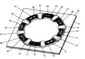
图1为本发明结构示意图Fig. 1 is a structural representation of the present invention
图2为本发明陀螺下定子立体图Fig. 2 is the perspective view of the lower stator of the gyroscope of the present invention
图3为本发明陀螺下定子结构示意图Fig. 3 is the structure schematic diagram of the lower stator of the gyroscope of the present invention
图4为本发明陀螺上定子立体图Fig. 4 is the perspective view of the upper stator of the gyroscope of the present invention
图5为本发明永磁环形转子结构示意图Fig. 5 is a schematic diagram of the structure of the permanent magnet ring rotor of the present invention
具体实施方式Detailed ways
如图1所示,本发明由上定子1、环形转子2、下定子3构成,连接方式为:下定子上设置右上第一公共侧向电容板6、右上第一检测侧向电容板7、右上第二检测侧向电容板8、右上第二公共侧向电容板9、左上第二公共侧向电容板11、左上第二检测侧向电容板12、左上第一检测侧向电容板13、左上第一公共侧向电容板14、左下第二公共侧向电容板16、左下第二检测侧向电容板17、左下第一检测侧向电容板18、左下第一公共侧向电容板19、右下第一公共侧向电容板21、右下第一检测侧向电容板22、右下第二检测侧向电容板23、右下第二公共侧向电容板24、右上公共内侧侧向电容板27、左上公共内侧侧向电容板29、左下公共内侧侧向电容板31、右下公共内侧侧向电容板33,下定子3通过这些侧向电容板与上定子1连接;这些侧向电容板与上定子1和下定子3一起围成一个环形空腔,环形转子2设置在这个空腔中。As shown in Figure 1, the present invention is composed of an upper stator 1, an annular rotor 2, and a lower stator 3, and the connection mode is as follows: the lower stator is provided with a first public lateral capacitance plate 6 on the upper right, a first detection lateral capacitance plate 7 on the upper right, The upper right second detection lateral capacitance plate 8, the upper right second common lateral capacitance plate 9, the upper left second common lateral capacitance plate 11, the upper left second detection lateral capacitance plate 12, the upper left first detection lateral capacitance plate 13, Upper left first common lateral capacitor plate 14, left lower second common lateral capacitor plate 16, left lower second detection lateral capacitor plate 17, left lower first detection lateral capacitor plate 18, left lower first common lateral capacitor plate 19, The first lower right common lateral capacitor plate 21, the lower right first detection lateral capacitor plate 22, the lower right second detection lateral capacitor plate 23, the lower right second common lateral capacitor plate 24, the upper right common inner lateral capacitor Plate 27, upper left common inner lateral capacitor plate 29, left lower common inner lateral capacitor plate 31, right lower common inner lateral capacitor plate 33, the lower stator 3 is connected with the upper stator 1 through these lateral capacitor plates; these lateral capacitors The plates together with the upper stator 1 and the lower stator 3 enclose an annular cavity in which the annular rotor 2 is arranged.
如图2、图3所示,下定子3是由以下部分构成:材料为玻璃的下定子基体4,材料为氮化硅的下定子绝缘层5,材料为Ni的右上第一公共侧向电容板6、右上第一检测侧向电容板7、右上第二检测侧向电容板8、右上第二公共侧向电容板9、左上第二公共侧向电容板11、左上第二检测侧向电容板12、左上第一检测侧向电容板13、左上第一公共侧向电容板14、左下第二公共侧向电容板16、左下第二检测侧向电容板17、左下第一检测侧向电容板18、左下第一公共侧向电容板19、右下第一公共侧向电容板21、右下第一检测侧向电容板22、右下第二检测侧向电容板23、右下第二公共侧向电容板24、右上公共内侧侧向电容板27、左上公共内侧侧向电容板29、左下公共内侧侧向电容板31、右下公共内侧侧向电容板33,材料为Cu的下定子右公共水平电容板42、下定子上公共水平电容板44、下定子左公共水平电容板46、下定子下公共水平电容板48、下定子右第一检测水平电容板82、下定子右第二检测水平电容板83、下定子上第一检测水平电容板84、下定子上第二检测水平电容板85、下定子左第二检测水平电容板86、下定子左第一检测水平电容板87、下定子下第一检测水平电容板88、下定子下第二检测水平电容板89,材料为Ni的下定子右上垂直支撑柱43、下定子左上垂直支撑柱45、下定子左下垂直支撑柱47、下定子右下垂直支撑柱49,材料为Ni的右外侧“门”型直流导线25、右内侧“门”型直流导线26、上外侧“门”型直流导线10、上内侧“门”型直流导线28、左外侧“门”型直流导线15、左内侧“门”型直流导线30、下外侧“门”型直流导线20、下内侧“门”型直流导线32,材料为Cu的下定子右水平线圈34、下定子右上水平线圈35、下定子上水平线圈36、下定子左上水平线圈37、下定子左水平线圈38、下定子左下水平线圈39、下定子下水平线圈40、下定子右下水平线圈41,材料为Ni的下定子右上侧向止挡柱50、下定子左上侧向止挡柱51、下定子左下侧向止挡柱52、下定子右下侧向止挡柱53。连接关系为:下定子绝缘层5置于下定子基体4之上。右上第一公共侧向电容板6、右上第一检测侧向电容板7、右上第二检测侧向电容板8、右上第二公共侧向电容板9、左上第二公共侧向电容板11、左上第二检测侧向电容板12、左上第一检测侧向电容板13、左上第一公共侧向电容板14、左下第二公共侧向电容板16、左下第二检测侧向电容板17、左下第一检测侧向电容板18、左下第一公共侧向电容板19、右下第一公共侧向电容板21、右下第一检测侧向电容板22、右下第二检测侧向电容板23、右下第二公共侧向电容板24、右上公共内侧侧向电容板27、左上公共内侧侧向电容板29、左下公共内侧侧向电容板31、右下公共内侧侧向电容板33置于下定子绝缘层5之上,下定子右公共水平电容板42、下定子上公共水平电容板44、下定子左公共水平电容板46、下定子下公共水平电容板48、下定子右第一检测水平电容板82置于下定子绝缘层5之上,下定子右上垂直支撑柱43、下定子左上垂直支撑柱45、下定子左下垂直支撑柱47、下定子右下垂直支撑柱49置于下定子绝缘层5之上,右外侧“门”型直流导线25、右内侧“门”型直流导线26、上外侧“门”型直流导线10、上内侧“门”型直流导线28、左外侧“门”型直流导线15、左内侧“门”型直流导线30、下外侧“门”型直流导线20、下内侧“门”型直流导线32置于下定子绝缘层5之上,下定子右水平线圈34、下定子右上水平线圈35、下定子上水平线圈36、下定子左上水平线圈37、下定子左水平线圈38、下定子左下水平线圈39、下定子下水平线圈40、下定子右下水平线圈41置于下定子绝缘层5之上。下定子右上侧向止挡柱50、下定子左上侧向止挡柱51、下定子左下侧向止挡柱52、下定子右下侧向止挡柱53置于下定子绝缘层5之上。右内侧“门”型直流导线26、右上公共内侧侧向电容板27、上内侧“门”型直流导线28、左上公共内侧侧向电容板29、左内侧“门”型直流导线30、左下公共内侧侧向电容板31、下内侧“门”型直流导线32、右下公共内侧侧向电容板33依次布置在以下定子绝缘层5中心为圆心的圆的圆周上。下定子右水平线圈34、下定子右第二检测水平电容板83、下定子右上水平线圈35、下定子上第一检测水平电容板84、下定子上水平线圈36、下定子上第二检测水平电容板85、下定子左上水平线圈37、下定子左第二检测水平电容板86、下定子左水平线圈38、下定子左第一检测水平电容板87、下定子左下水平线圈39、下定子下第一检测水平电容板88、下定子下水平线圈40、下定子下第二检测水平电容板89、下定子右下水平线圈41、下定子右第一检测水平电容板82依次布置在以下定子绝缘层5中心为圆心的圆周上,这些结构的厚度相同,且位于右内侧“门”型直流导线26、右上公共内侧侧向电容板27、上内侧“门”型直流导线28、左上公共内侧侧向电容板29、左内侧“门”型直流导线30、左下公共内侧侧向电容板31、下内侧“门”型直流导线32、右下公共内侧侧向电容板33的外侧。右上第一公共侧向电容板6、右上第一检测侧向电容板7、右上第二检测侧向电容板8、右上第二公共侧向电容板9,上外侧“门”型直流导线10,左上第二公共侧向电容板11、左上第二检测侧向电容板12、左上第一检测侧向电容板13、左上第一公共侧向电容板14,左外侧“门”型直流导线15,左下第二公共侧向电容板16、左下第二检测侧向电容板17、左下第一检测侧向电容板18、左下第一公共侧向电容板19,下外侧“门”型直流导线20,右下第一公共侧向电容板21、右下第一检测侧向电容板22、右下第二检测侧向电容板23、右下第二公共侧向电容板24,右外侧“门”型直流导线25依次布置在以下定子绝缘层5中心为圆心的圆周上,且位于下定子右水平线圈34、下定子右第二检测水平电容板83、下定子右上水平线圈35、下定子上第一检测水平电容板84、下定子上水平线圈36、下定子上第二检测水平电容板85、下定子左上水平线圈37、下定子左第二检测水平电容板86、下定子左水平线圈38、下定子左第一检测水平电容板87、下定子左下水平线圈39、下定子下第一检测水平电容板88、下定子下水平线圈40、下定子下第二检测水平电容板89、下定子右下水平线圈41、下定子右第一检测水平电容板82的外侧。下定子右公共水平电容板42设置在下定子右水平线圈34的中间,且两者厚度相同。下定子右上垂直支撑柱43设置在下定子右上水平线圈35的中间,下定子右上垂直支撑柱43的厚度大于下定子右上水平线圈35的厚度。下定子上公共水平电容板44设置在下定子上水平线圈36的中间,且厚度相同。下定子左上垂直支撑柱45设置在下定子左上水平线圈37的中间,下定子左上垂直支撑柱45的厚度大于下定子左上水平线圈37的厚度。下定子左公共水平电容板46设置在下定子左水平线圈38的中间,且厚度相同。下定子左下垂直支撑柱47设置在下定子左下水平线圈39的中间,下定子左下垂直支撑柱47的厚度大于下定子左下水平线圈39的厚度。下定子下公共水平电容板48设置在下定子下水平线圈40的中间,且厚度相同。下定子右下垂直支撑柱49设置在下定子右下水平线圈41的中间,下定子右下垂直支撑柱49的厚度大于下定子右下水平线圈41的厚度。As shown in Figure 2 and Figure 3, the lower stator 3 is composed of the following parts: the lower stator base 4 made of glass, the lower stator insulating layer 5 made of silicon nitride, and the upper right first common lateral capacitor made of Ni Plate 6, upper right first detection lateral capacitance plate 7, upper right second detection lateral capacitance plate 8, right upper second public lateral capacitance plate 9, left upper second public lateral capacitance plate 11, left upper second detection lateral capacitance Plate 12, upper left first detection lateral capacitance plate 13, upper left first common lateral capacitance plate 14, lower left second common lateral capacitance plate 16, lower left second detection lateral capacitance plate 17, lower left first detection lateral capacitance Plate 18, the first lower left common lateral capacitor plate 19, the lower right first common lateral capacitor plate 21, the lower right first detection lateral capacitor plate 22, the lower right second detection lateral capacitor plate 23, the lower right second Common lateral capacitor plate 24, upper right common inner lateral capacitor plate 27, upper left common inner lateral capacitor plate 29, lower left common inner lateral capacitor plate 31, lower right common inner lateral capacitor plate 33, the material is the lower stator of Cu Right public horizontal capacitor plate 42, public horizontal capacitor plate 44 on the lower stator, lower stator left public horizontal capacitor plate 46, lower stator common horizontal capacitor plate 48, lower stator right first detection horizontal capacitor plate 82, lower stator right second Detection level capacitance plate 83, the first detection level capacitance plate 84 on the lower stator, the second detection level capacitance plate 85 on the lower stator, the second detection level capacitance plate 86 on the left side of the lower stator, the first detection level capacitance plate 87 on the left side of the lower stator, The first detection horizontal capacitor plate 88 under the lower stator, the second detection horizontal capacitor plate 89 under the lower stator, the material is the upper right vertical support column 43 of the lower stator of Ni, the upper left vertical support column 45 of the lower stator, the lower left vertical support column 47 of the lower stator, The lower right vertical support column 49 of the lower stator, the material is the right outer "door" type DC wire 25, the right inner "door" type DC wire 26, the upper outer "door" type DC wire 10, the upper inner "door" type DC wire 10, and the material is Ni. Lead wire 28, left outer "door" type DC wire 15, left inner "door" type DC wire 30, lower outer "door" type DC wire 20, lower inner "door" type DC wire 32, the material is the lower stator right of Cu Horizontal coil 34, lower stator upper right horizontal coil 35, lower stator upper horizontal coil 36, lower stator upper left horizontal coil 37, lower stator left horizontal coil 38, lower stator left lower horizontal coil 39, lower stator lower horizontal coil 40, lower stator right lower Horizontal coil 41, material is Ni lower stator upper right lateral stop post 50, lower stator upper left lateral stop post 51, lower stator left lower lateral stop post 52, lower stator right lower lateral stop post 53. The connection relationship is: the lower stator insulating layer 5 is placed on the lower stator base 4 . The first upper right common lateral capacitor plate 6, the upper right first detection lateral capacitor plate 7, the upper right second detection lateral capacitor plate 8, the upper right second common lateral capacitor plate 9, the upper left second common lateral capacitor plate 11, Upper left second detection lateral capacitor plate 12, upper left first detection lateral capacitor plate 13, upper left first public lateral capacitor plate 14, left lower second common lateral capacitor plate 16, left lower second detection lateral capacitor plate 17, The lower left first detection lateral capacitance plate 18, the lower left first common lateral capacitance plate 19, the lower right first public lateral capacitance plate 21, the lower right first detection lateral capacitance plate 22, the lower right second detection lateral capacitance Plate 23, the second lower right common lateral capacitor plate 24, the upper right common inner lateral capacitor plate 27, the upper left common inner lateral capacitor plate 29, the lower left common inner lateral capacitor plate 31, the lower right common inner lateral capacitor plate 33 Placed on the lower stator insulating layer 5, the lower stator right public horizontal capacitor plate 42, the lower stator upper public horizontal capacitor plate 44, the lower stator left public horizontal capacitor plate 46, the lower stator common horizontal capacitor plate 48, the lower stator right second capacitor plate A detection horizontal capacitor plate 82 is placed on the lower stator insulation layer 5, the upper right vertical support column 43 of the lower stator, the upper left vertical support column 45 of the lower stator, the lower left vertical support column 47 of the lower stator, and the lower right vertical support column 49 of the lower stator. On the lower stator insulating layer 5, the right outer "door" type DC wire 25, the right inner "door" type DC wire 26, the upper outer "door" type DC wire 10, the upper inner "door" type DC wire 28, the left outer side "Door" type DC wire 15, left inner "door" type DC wire 30, lower outer "door" type DC wire 20, lower inner "door" type DC wire 32 are placed on the lower stator insulating layer 5, and the lower stator right Horizontal coil 34, lower stator upper right horizontal coil 35, lower stator upper horizontal coil 36, lower stator upper left horizontal coil 37, lower stator left horizontal coil 38, lower stator left lower horizontal coil 39, lower stator lower horizontal coil 40, lower stator right lower The horizontal coil 41 is placed on the lower stator insulation layer 5 . The lower stator right upper side stop post 50 , the lower stator upper left side stop post 51 , the lower stator left lower side stop post 52 , the lower stator right lower side stop post 53 are placed on the lower stator insulating layer 5 . Right inner "door" type DC conductor 26, upper right common inner lateral capacitor plate 27, upper inner "door" type DC conductor 28, left upper common inner lateral capacitor plate 29, left inner "door" type direct current conductor 30, left lower common The inner lateral capacitor plate 31 , the lower inner “gate” type DC conductor 32 , and the lower right common inner lateral capacitor plate 33 are sequentially arranged on the circumference of the circle whose center is the center of the lower stator insulating layer 5 . Lower stator right horizontal coil 34, lower stator right second detection horizontal capacitor plate 83, lower stator right upper horizontal coil 35, lower stator upper first detection horizontal capacitor plate 84, lower stator upper horizontal coil 36, lower stator upper second detection level Capacitor plate 85, lower stator left upper horizontal coil 37, lower stator left second detection horizontal capacitor plate 86, lower stator left horizontal coil 38, lower stator left first detection horizontal capacitor plate 87, lower stator left lower horizontal coil 39, lower stator The first detection horizontal capacitance plate 88, the lower stator horizontal coil 40, the second detection horizontal capacitance plate 89 under the lower stator, the lower stator right lower horizontal coil 41, and the lower stator right first detection horizontal capacitance plate 82 are arranged successively on the following stator insulation On the circle where the center of layer 5 is the center of the circle, these structures have the same thickness and are located on the right inner "gate" type DC conductor 26, the upper right common inner side capacitor plate 27, the upper inner "gate" type DC conductor 28, and the upper left common inner side To the outside of the capacitor plate 29, the left inner side "gate" type DC conductor 30, the lower left common inner side towards the capacitor plate 31, the lower inner side "gate" type DC conductor 32, the right lower common inner side toward the capacitor plate 33. The upper right first public lateral capacitor plate 6, the upper right first detection lateral capacitor plate 7, the upper right second detection lateral capacitor plate 8, the upper right second common lateral capacitor plate 9, the upper outer “gate” type DC conductor 10, The second upper left common lateral capacitor plate 11, the upper left second detection lateral capacitor plate 12, the upper left first detection lateral capacitor plate 13, the upper left first common lateral capacitor plate 14, the left outer “gate” type DC conductor 15, The second lower left common lateral capacitor plate 16, the lower left second detection lateral capacitor plate 17, the lower left first detection lateral capacitor plate 18, the lower left first public lateral capacitor plate 19, the lower outer “gate” type DC conductor 20, The lower right first common lateral capacitor plate 21, the lower right first detection lateral capacitor plate 22, the lower right second detection lateral capacitor plate 23, the lower right second common lateral capacitor plate 24, and the right outer “door” type The DC wires 25 are arranged successively on the circumference of the following stator insulation layer 5 as the center of the circle, and are located at the right horizontal coil 34 of the lower stator, the second detection horizontal capacitor plate 83 of the lower stator right, the upper right horizontal coil 35 of the lower stator, and the first horizontal coil 35 of the lower stator. Detect horizontal capacitor plate 84, lower stator upper horizontal coil 36, second detection horizontal capacitor plate 85 on lower stator, lower stator left upper horizontal coil 37, lower stator left second detection horizontal capacitor plate 86, lower stator left horizontal coil 38, lower stator Sub left first detection horizontal capacitor plate 87, lower stator left lower horizontal coil 39, lower stator first detection horizontal capacitor plate 88, lower stator lower horizontal coil 40, lower stator second detection horizontal capacitor plate 89, lower stator right lower The horizontal coil 41 and the lower stator right first detect the outside of the horizontal capacitor plate 82 . The lower stator right common horizontal capacitor plate 42 is arranged in the middle of the lower stator right horizontal coil 34, and both have the same thickness. The upper right vertical support column 43 of the lower stator is arranged in the middle of the upper right horizontal coil 35 of the lower stator, and the thickness of the upper right vertical support column 43 of the lower stator is greater than the thickness of the upper right horizontal coil 35 of the lower stator. The common horizontal capacitor plate 44 on the lower stator is arranged in the middle of the horizontal coil 36 on the lower stator, and has the same thickness. The upper left vertical support column 45 of the lower stator is arranged in the middle of the upper left horizontal coil 37 of the lower stator, and the thickness of the upper left vertical support column 45 of the lower stator is greater than the thickness of the upper left horizontal coil 37 of the lower stator. The lower stator left common horizontal capacitor plate 46 is arranged in the middle of the lower stator left horizontal coil 38 and has the same thickness. The lower left vertical support column 47 of the lower stator is arranged in the middle of the lower left horizontal coil 39 of the lower stator, and the thickness of the lower left vertical support column 47 of the lower stator is greater than the thickness of the lower left horizontal coil 39 of the lower stator. The common horizontal capacitive plate 48 under the lower stator is arranged in the middle of the horizontal coil 40 under the lower stator, and has the same thickness. The lower right vertical support column 49 of the lower stator is arranged in the middle of the lower right horizontal coil 41 of the lower stator, and the thickness of the lower right vertical support column 49 of the lower stator is greater than the thickness of the lower right horizontal coil 41 of the lower stator.
如图4所示,上定子1由以下部分构成:材料为玻璃的上定子基体54、材料为氮化硅的上定子绝缘层55、材料为Cu的上定子右上水平线圈56、材料为Cu的上定子上第一检测水平电容板58、材料为Cu的上定子上水平线圈59、材料为Cu的上定子上第二检测水平电容板61、材料为Cu的上定子左上水平线圈62、材料为Cu的上定子左第二检测水平电容板64、材料为Cu的上定子左水平线圈65、材料为Cu的上定子左第一检测水平电容板67、材料为Cu的上定子左下水平线圈68、材料为Cu的上定子下第一检测水平电容板70、材料为Cu的上定子下水平线圈71、材料为Cu的上定子下第二检测水平电容板73、材料为Cu的上定子右下水平线圈74、材料为Cu的上定子右第一检测水平电容板76、材料为Cu的上定子右水平线圈77、材料为Cu的上定子右第二检测水平电容板79、材料为Ni的上定子右上垂直支撑柱57、材料为Cu的上定子上公共水平电容板60、材料为Ni的上定子左上垂直支撑柱63、材料为Cu的上定子左公共水平电容板66、材料为Ni的上定子左下垂直支撑柱69、材料为Cu的上定子下公共水平电容板72、材料为Ni的上定子右下垂直支撑柱75、材料为Cu的上定子右公共水平电容板78。连接关系为:上定子绝缘层55设置在上定子基体54之上,上定子右上水平线圈56、上定子上第一检测水平电容板58、上定子上水平线圈59、上定子上第二检测水平电容板61、上定子左上水平线圈62、上定子左第二检测水平电容板64、上定子左水平线圈65、上定子左第一检测水平电容板67、上定子左下水平线圈68、上定子下第一检测水平电容板70、上定子下水平线圈71、上定子下第二检测水平电容板73、上定子右下水平线圈74、上定子右第一检测水平电容板76、上定子右水平线圈77、上定子右第二检测水平电容板79、上定子右上垂直支撑柱57、上定子上公共水平电容板60、上定子左上垂直支撑柱63、上定子左公共水平电容板66、上定子左下垂直支撑柱69、上定子下公共水平电容板72、上定子右下垂直支撑柱75、上定子右公共水平电容板78设置在上定子绝缘层55之上。上定子右上水平线圈56、上定子上第一检测水平电容板58、上定子上水平线圈59、上定子上第二检测水平电容板61、上定子左上水平线圈62、上定子左第二检测水平电容板64、上定子左水平线圈65、上定子左第一检测水平电容板67、上定子左下水平线圈68、上定子下第一检测水平电容板70、上定子下水平线圈71、上定子下第二检测水平电容板73、上定子右下水平线圈74、上定子右第一检测水平电容板76、上定子右水平线圈77、上定子右第二检测水平电容板79依次布置在以上定子绝缘层55中心为圆心的圆周上,且厚度相同。上定子右上垂直支撑柱57设置在上定子右上水平线圈56的中间,上定子右上垂直支撑柱57的厚度大于上定子右上水平线圈56的厚度。上定子上公共水平电容板60设置在上定子上水平线圈59的中间,且厚度相同。上定子左上垂直支撑柱63设置在上定子左上水平线圈62的中间,且上定子左上垂直支撑柱63的厚度大于上定子左上水平线圈62的厚度。上定子左公共水平电容板66设置在上定子左水平线圈65的中间,且厚度相同。上定子左下垂直支撑柱69设置在上定子左下水平线圈68的中间,且上定子左下垂直支撑柱69的厚度大于上定子左下水平线圈68的厚度。上定子下公共水平电容板72设置在上定子下水平线圈71的中间,且厚度相同。上定子右下垂直支撑柱75设置上定子右下水平线圈74的中间,且上定子右下垂直支撑柱75的厚度大于上定子右下水平线圈厚度74。上定子右公共水平电容板78设置在上定子右水平线圈77的中间,且厚度相同。As shown in Figure 4, the upper stator 1 is composed of the following parts: the
如图5所示,环形转子2为永磁体,N极80在环形转子2的上表面,S极81在环形转子的下表面,其极化方向与圆环的中心轴线平行。As shown in FIG. 5 , the
在陀螺的装配过程中,应注意保证上定子1的上定子右第二检测水平电容板79、上定子上第一检测水平电容板58、上定子上第二检测水平电容板61、上定子左第二检测水平电容板64、上定子左第一检测水平电容板67、上定子下第一检测水平电容板70、上定子下第二检测水平电容板73、上定子右第一检测水平电容板76与下定子3的下定子左第二检测水平电容板86、下定子上第二检测水平电容板85、下定子上第一检测水平电容板84、下定子右第二检测水平电容板83、下定子右第一检测水平电容板82、下定子下第二检测水平电容板89、下定子下第一检测水平电容板88、下定子左第一检测水平电容板87依次相对。During the assembly process of the gyroscope, care should be taken to ensure that the upper stator right second detection
陀螺工作时,环形转子2先停在下定子3的下定子右上垂直支撑柱43、下定子左上垂直支撑柱45、下定子左下垂直支撑柱47、下定子右下垂直支撑柱49上,垂直支撑柱作用一方面避免环形转子2与线圈和电容的电气导通,一方面可以减少环形转子2启动时的摩擦力。During the gyroscope work, the
上定子左水平线圈65、上定子下水平线圈71、上定子右水平线圈77、上定子上水平线圈59及下定子右水平线圈34、下定子下水平线圈40、下定子左水平线圈38、下定子上水平线圈36分别施加直流电流,产生轴向悬浮力,利用斥力原理,使环形转子2轴向悬浮,右内侧“门”型直流导线26、右外侧“门”型直流导线25、上内侧“门”型直流导线28、上外侧“门”型直流导线10、左内侧“门”型直流导线30、左外侧“门”型直流导线15、下内侧“门”型直流导线32、下外侧“门”型直流导线20分别通直流电使环形转子2径向悬浮并保持稳定。需要指出的是直流电流的大小是根据位置检测的结果实时调整。Upper stator left
上定子右上水平线圈56、上定子左上水平线圈62、上定子左下水平线圈68、上定子右下水平线圈74通相位依次相差90度交流电,下定子左上水平线圈37、下定子右上水平线圈35、下定子右下水平线圈41、下定子左下水平线圈39通相位依次相差90度交流电,上定子右上水平线圈56、下定子左上水平线圈37交流电相位相同,上定子左上水平线圈62、下定子右上水平线圈35交流电相位相同,上定子左下水平线圈68、下定子右下水平线圈41交流电相位相同,上定子右下水平线圈74、下定子左下水平线圈39交流电相位相同,于是产生旋转电磁场,与环形转子2一起构成异步感应电机,带动环形转子2高速旋转,同时这种相位通电方式可使上下水平线圈交流电对环形转子的稳定悬浮影响最小。Upper stator right upper
在右上第一检测侧向电容板7、右上第二检测侧向电容板8加载波,左上第二检测侧向电容板12、左上第一检测侧向电容板13加载波,在左下第二检测侧向电容板17、左下第一检测侧向电容板18加载波,在右下第一检测侧向电容板22、右下第二检测侧向电容板23加载波,在下定子上第一检测水平电容板84、下定子上第二检测水平电容板85加载波,在下定子左第二检测水平电容板86、下定子左第一检测水平电容板87加载波,在下定子下第一检测水平电容板88、下定子下第二检测水平电容板89加载波,在下定子右第一检测水平电容板82、下定子右第二检测水平电容板83加载波,在上定子上第一检测水平电容板58、上定子上第二检测水平电容板61加载波,在上定子左第二检测水平电容板64、上定子左第一检测水平电容板67加载波,在上定子下第一检测水平电容板70、上定子下第二检测水平电容板73加载波,在上定子右第一检测水平电容板76、上定子右第二检测水平电容板79加载波,本自然段所述的载波频率各不相同,上定子上公共水平电容板60、上定子左公共水平电容板66、上定子下公共水平电容板72、上定子右公共水平电容板78、下定子上公共水平电容板44、下定子左公共水平电容板46、下定子下公共水平电容板48、下定子右公共水平电容板42及右上第一公共侧向电容板6、右上第二公共侧向电容板9、左上第二公共侧向电容板11、左上第一公共侧向电容板14、左下第二公共侧向电容板16、左下第一公共侧向电容板19、右下第一公共侧向电容板21、右下第二公共侧向电容板24、右上公共内侧侧向电容板27、左上公共内侧侧向电容板29、左下公共内侧侧向电容板31、右下公共内侧侧向电容板33用线连在一起,在外加载波信号的作用下,输出检测信号,经分频检测及放大解调后续电路处理就能输出环形转子的位置,根据力矩再平衡原理敏感外界输入角速度。同时,根据环形转子的位置信息,实时调整上定子左水平线圈65、上定子下水平线圈71、上定子右水平线圈77、上定子上水平线圈59、下定子右水平线圈34、下定子下水平线圈40、下定子左水平线圈38、下定子上水平线圈36及右内侧“门”型直流导线26、右外侧“门”型直流导线25、上内侧“门”型直流导线28、上外侧“门”型直流导线10、左内侧“门”型直流导线30、左外侧“门”型直流导线15、下内侧“门”型直流导线32、下外侧“门”型直流导线20中的直流电流,使环形转子悬浮稳定。On the upper right, the first detection lateral capacitance plate 7, the upper right second detection lateral capacitance plate 8 load waves, the upper left second detection lateral capacitance plate 12, the left upper first detection lateral capacitance plate 13 load waves, and the lower left second detection The side capacitor plate 17, the first detection side capacitor plate 18 on the lower left loads the wave, the first detection side capacitor plate 22 on the lower right, the second detection side capacitor plate 23 loads the wave on the lower right, and the first detection on the lower stator The horizontal capacitance plate 84, the second detection horizontal capacitance plate 85 loading wave on the lower stator, the second detection horizontal capacitance plate 86 on the lower stator left, the first detection horizontal capacitance plate 87 loading wave on the left side of the lower stator, the first detection under the lower stator The horizontal capacitance plate 88, the second detection horizontal capacitance plate 89 loading wave under the lower stator, the first detection horizontal capacitance plate 82 on the lower stator right, the second detection horizontal capacitance plate 83 loading wave on the lower stator right, the first detection on the upper stator The horizontal capacitance plate 58, the second detection horizontal capacitance plate 61 loading wave on the upper stator, the second detection horizontal capacitance plate 64 on the upper stator left, the first detection horizontal capacitance plate 67 loading wave on the left side of the upper stator, the first detection under the upper stator The horizontal capacitor plate 70, the second detection horizontal capacitor plate 73 loading wave under the upper stator, the first detection horizontal capacitor plate 76 on the right side of the upper stator, the second detection horizontal capacitor plate 79 loading wave on the right side of the upper stator, the carrier wave described in this natural paragraph The frequencies are different, the public horizontal capacitor plate 60 on the upper stator, the left public horizontal capacitor plate 66 on the upper stator, the public horizontal capacitor plate 72 under the upper stator, the right public horizontal capacitor plate 78 on the upper stator, the public horizontal capacitor plate 44 on the lower stator, Lower stator left common horizontal capacitor plate 46, lower stator common horizontal capacitor plate 48, lower stator right common horizontal capacitor plate 42 and upper right first public lateral capacitor plate 6, upper right second common lateral capacitor plate 9, upper left second Common lateral capacitor plate 11, upper left first common lateral capacitor plate 14, lower left second common lateral capacitor plate 16, lower left first common lateral capacitor plate 19, lower right first common lateral capacitor plate 21, lower right The second public lateral capacitor plate 24, the upper right common inner lateral capacitor plate 27, the upper left common inner lateral capacitor plate 29, the lower left common inner lateral capacitor plate 31, the lower right common inner lateral capacitor plate 33 are connected together with lines , under the action of the external loading wave signal, the detection signal is output, and the position of the ring rotor can be output after the frequency division detection and subsequent circuit processing of amplification and demodulation, and the external input angular velocity is sensitive according to the principle of torque rebalancing. At the same time, according to the position information of the annular rotor, adjust the left
上定子1、下定子3、环形转子2采用常规的微机械加工方法加工,绝缘层氮化硅采用PEVCD制作,水平电容板、线圈采用光刻、电镀Cu工艺制作。侧向电容板、垂直支撑柱、侧向支撑柱、“门”型直流线圈采用光刻、电镀Ni相应工艺制成,环形转子2采用光刻电镀稀土永磁钴镍锰磷,最后充磁制作。The upper stator 1, the lower stator 3, and the
Claims (5)
Translated fromChinesePriority Applications (1)
| Application Number | Priority Date | Filing Date | Title |
|---|---|---|---|
| CNB2006100274064ACN100458366C (en) | 2006-06-08 | 2006-06-08 | Active suspension permanent magnet ring rotor acynchronous induction micro machinery gyroscope gyroscope |
Applications Claiming Priority (1)
| Application Number | Priority Date | Filing Date | Title |
|---|---|---|---|
| CNB2006100274064ACN100458366C (en) | 2006-06-08 | 2006-06-08 | Active suspension permanent magnet ring rotor acynchronous induction micro machinery gyroscope gyroscope |
Publications (2)
| Publication Number | Publication Date |
|---|---|
| CN1858552A CN1858552A (en) | 2006-11-08 |
| CN100458366Ctrue CN100458366C (en) | 2009-02-04 |
Family
ID=37297478
Family Applications (1)
| Application Number | Title | Priority Date | Filing Date |
|---|---|---|---|
| CNB2006100274064AExpired - Fee RelatedCN100458366C (en) | 2006-06-08 | 2006-06-08 | Active suspension permanent magnet ring rotor acynchronous induction micro machinery gyroscope gyroscope |
Country Status (1)
| Country | Link |
|---|---|
| CN (1) | CN100458366C (en) |
Families Citing this family (2)
| Publication number | Priority date | Publication date | Assignee | Title |
|---|---|---|---|---|
| CN102506840A (en)* | 2011-09-26 | 2012-06-20 | 中国船舶重工集团公司第七0七研究所 | Dynamically tuned gyroscope of high-precision hemispherical dynamic pressure motor |
| CN110672082B (en)* | 2019-12-06 | 2020-02-28 | 中国人民解放军国防科技大学 | Concentrated mass vibrating gyroscope based on push-up magnetic suspension platform |
Citations (8)
| Publication number | Priority date | Publication date | Assignee | Title |
|---|---|---|---|---|
| US3918310A (en)* | 1974-06-14 | 1975-11-11 | Singer Co | Capacitive sensing system |
| JPH10141959A (en)* | 1996-11-08 | 1998-05-29 | Tokimec Inc | Gyro apparatus |
| RU2126135C1 (en)* | 1997-01-16 | 1999-02-10 | Государственное предприятие "Ижевский механический завод" | Magnetospheric gyroscope |
| WO2001020259A1 (en)* | 1999-09-17 | 2001-03-22 | Kionix, Inc. | Electrically decoupled micromachined gyroscope |
| CN1477374A (en)* | 2003-07-10 | 2004-02-25 | 上海交通大学 | Magnetic Suspension Rotor Azimuth Micro Gyro |
| CN1570563A (en)* | 2004-04-29 | 2005-01-26 | 上海交通大学 | Suspended rotor MEMS micro-gyroscope utilizing static and charge relaxation to work |
| CN1710383A (en)* | 2005-06-17 | 2005-12-21 | 东南大学 | Tuned MEMS Gyroscope |
| CN1731089A (en)* | 2005-08-11 | 2006-02-08 | 上海交通大学 | Disk Micromechanical Gyroscope Based on Acoustic Levitation |
- 2006
- 2006-06-08CNCNB2006100274064Apatent/CN100458366C/ennot_activeExpired - Fee Related
Patent Citations (8)
| Publication number | Priority date | Publication date | Assignee | Title |
|---|---|---|---|---|
| US3918310A (en)* | 1974-06-14 | 1975-11-11 | Singer Co | Capacitive sensing system |
| JPH10141959A (en)* | 1996-11-08 | 1998-05-29 | Tokimec Inc | Gyro apparatus |
| RU2126135C1 (en)* | 1997-01-16 | 1999-02-10 | Государственное предприятие "Ижевский механический завод" | Magnetospheric gyroscope |
| WO2001020259A1 (en)* | 1999-09-17 | 2001-03-22 | Kionix, Inc. | Electrically decoupled micromachined gyroscope |
| CN1477374A (en)* | 2003-07-10 | 2004-02-25 | 上海交通大学 | Magnetic Suspension Rotor Azimuth Micro Gyro |
| CN1570563A (en)* | 2004-04-29 | 2005-01-26 | 上海交通大学 | Suspended rotor MEMS micro-gyroscope utilizing static and charge relaxation to work |
| CN1710383A (en)* | 2005-06-17 | 2005-12-21 | 东南大学 | Tuned MEMS Gyroscope |
| CN1731089A (en)* | 2005-08-11 | 2006-02-08 | 上海交通大学 | Disk Micromechanical Gyroscope Based on Acoustic Levitation |
Non-Patent Citations (2)
| Title |
|---|
| 磁悬浮转子微陀螺悬浮线圈的结构设计. 吴校生等.上海交通大学学报,第39卷第1期. 2005* |
| 磁悬浮转子微陀螺的微细加工工艺研究. 吴校生等.微细加工技术,第1期. 2004* |
Also Published As
| Publication number | Publication date |
|---|---|
| CN1858552A (en) | 2006-11-08 |
Similar Documents
| Publication | Publication Date | Title |
|---|---|---|
| CN101561275B (en) | Suspension rotor micro gyro by utilizing electromagnetism and charge relaxation to work | |
| CN1818552A (en) | Micro-rotation top with double-stator electromagnetic suspension rotor | |
| US11277079B2 (en) | Bearing-less electrostatic flywheel | |
| CN100504297C (en) | Internally stable electromagnetic levitation ring rotor micro-rotating gyroscope | |
| CN102564409B (en) | Rotor type micromechanical gyroscope with electromagnetically-driven framework structure | |
| CN100458366C (en) | Active suspension permanent magnet ring rotor acynchronous induction micro machinery gyroscope gyroscope | |
| CN100552382C (en) | Circular and multi-ring axial radial magnetization permanent magnet antimagnetic rotor induction rotating micro gyroscope | |
| CN100510754C (en) | Suspension type diamagnetic sensitive mass micro accelerometer | |
| CN100489452C (en) | Diamagnetic rotor electromagnetic induction driving micro-gyroscope | |
| CN101216308A (en) | Circular and multi-ring axially magnetized permanent magnet antimagnetic rotor induction rotating micro gyroscope | |
| CN101021419A (en) | Diamagnetic suspension rotor electrostatic driving micro-gyroscope | |
| CN100483074C (en) | Electromagnetic levitation static driven micro-rotation gyro | |
| CN100489453C (en) | Static support suspended electromagnetic induction rotation micro-gyro | |
| CN1920480A (en) | Two-rotor statically stable electromagnetic suspension micro-rotary gyro | |
| CN100543417C (en) | Dual-mode anti-magnetic rotor inductive rotating microgyroscope | |
| CN101216309B (en) | Circular and multi-ring axially magnetized permanent magnet anti-magnetic rotor electrostatic rotating micro gyroscope | |
| CN100552381C (en) | Fluid and rotary drive integral flexible hard magnet compensation type static moment-increasing gyroscope | |
| CN100510628C (en) | Permanent-magnet dimagnetic combined suspension rotor micro gyroscope | |
| CN100510626C (en) | Magnetic field controllable dimagnetic stable suspersion rotor micro gyroscope | |
| CN100566121C (en) | Stator Embedded Electromagnetic Levitation Rotor Micromotor | |
| CN100523730C (en) | Flexible static compensation type static moment-increasing fluid gyroscope | |
| CN103557852B (en) | A kind of ball dish rotator type micromechanical gyro | |
| Sreejith et al. | Design of Miniature Motor for a Hybrid Gyroscope | |
| CN101561276B (en) | Suspended Rotor Micro Gyroscope Using Electromagnetic and Corona | |
| CN100526805C (en) | Fluid and rotary drive integral flexible static compensation type coil moment-increasing gyroscope |
Legal Events
| Date | Code | Title | Description |
|---|---|---|---|
| C06 | Publication | ||
| PB01 | Publication | ||
| C10 | Entry into substantive examination | ||
| SE01 | Entry into force of request for substantive examination | ||
| C14 | Grant of patent or utility model | ||
| GR01 | Patent grant | ||
| C17 | Cessation of patent right | ||
| CF01 | Termination of patent right due to non-payment of annual fee | Granted publication date:20090204 Termination date:20110608 |