CN100457035C - Optical coherence tomography system for the examination of human or animal tissue or of organs - Google Patents
Optical coherence tomography system for the examination of human or animal tissue or of organsDownload PDFInfo
- Publication number
- CN100457035C CN100457035CCNB2004100459004ACN200410045900ACN100457035CCN 100457035 CCN100457035 CCN 100457035CCN B2004100459004 ACNB2004100459004 ACN B2004100459004ACN 200410045900 ACN200410045900 ACN 200410045900ACN 100457035 CCN100457035 CCN 100457035C
- Authority
- CN
- China
- Prior art keywords
- cross
- image
- dimensional
- organ
- coherence tomography
- Prior art date
- Legal status (The legal status is an assumption and is not a legal conclusion. Google has not performed a legal analysis and makes no representation as to the accuracy of the status listed.)
- Expired - Fee Related
Links
- 210000000056organAnatomy0.000titleclaimsabstractdescription32
- 238000012014optical coherence tomographyMethods0.000titleclaimsabstractdescription25
- 241001465754MetazoaSpecies0.000titleclaimsabstractdescription4
- 238000006073displacement reactionMethods0.000claimsdescription15
- 238000007689inspectionMethods0.000claimsdescription7
- 230000001960triggered effectEffects0.000claimsdescription3
- 230000000694effectsEffects0.000claimsdescription2
- 239000003550markerSubstances0.000claimsdescription2
- 238000011156evaluationMethods0.000abstract3
- 210000004204blood vesselAnatomy0.000description15
- 238000003325tomographyMethods0.000description15
- 238000000034methodMethods0.000description9
- 230000000875corresponding effectEffects0.000description7
- 238000009877renderingMethods0.000description6
- 230000000747cardiac effectEffects0.000description4
- 238000001514detection methodMethods0.000description4
- 230000000877morphologic effectEffects0.000description4
- 238000010586diagramMethods0.000description3
- 230000000241respiratory effectEffects0.000description3
- 238000002604ultrasonographyMethods0.000description3
- 208000037273Pathologic ProcessesDiseases0.000description2
- 210000003484anatomyAnatomy0.000description2
- 238000002583angiographyMethods0.000description2
- 230000003287optical effectEffects0.000description2
- 230000009054pathological processEffects0.000description2
- 208000032544CicatrixDiseases0.000description1
- 206010061216InfarctionDiseases0.000description1
- 238000005452bendingMethods0.000description1
- 210000004351coronary vesselAnatomy0.000description1
- 230000002596correlated effectEffects0.000description1
- 238000003745diagnosisMethods0.000description1
- 238000005562fadingMethods0.000description1
- 210000001035gastrointestinal tractAnatomy0.000description1
- 238000003384imaging methodMethods0.000description1
- 230000007574infarctionEffects0.000description1
- 230000010354integrationEffects0.000description1
- 238000005305interferometryMethods0.000description1
- 230000003902lesionEffects0.000description1
- 230000007246mechanismEffects0.000description1
- 238000002558medical inspectionMethods0.000description1
- 230000001575pathological effectEffects0.000description1
- 230000005855radiationEffects0.000description1
- 238000001454recorded imageMethods0.000description1
- 231100000241scarToxicity0.000description1
- 230000037387scarsEffects0.000description1
- 230000002123temporal effectEffects0.000description1
- 230000006439vascular pathologyEffects0.000description1
- 238000012800visualizationMethods0.000description1
Images

Classifications
- A—HUMAN NECESSITIES
- A61—MEDICAL OR VETERINARY SCIENCE; HYGIENE
- A61B—DIAGNOSIS; SURGERY; IDENTIFICATION
- A61B5/00—Measuring for diagnostic purposes; Identification of persons
- A61B5/06—Devices, other than using radiation, for detecting or locating foreign bodies ; Determining position of diagnostic devices within or on the body of the patient
- A61B5/065—Determining position of the probe employing exclusively positioning means located on or in the probe, e.g. using position sensors arranged on the probe
- A—HUMAN NECESSITIES
- A61—MEDICAL OR VETERINARY SCIENCE; HYGIENE
- A61B—DIAGNOSIS; SURGERY; IDENTIFICATION
- A61B5/00—Measuring for diagnostic purposes; Identification of persons
- A61B5/0059—Measuring for diagnostic purposes; Identification of persons using light, e.g. diagnosis by transillumination, diascopy, fluorescence
- A61B5/0062—Arrangements for scanning
- A61B5/0066—Optical coherence imaging
- A—HUMAN NECESSITIES
- A61—MEDICAL OR VETERINARY SCIENCE; HYGIENE
- A61B—DIAGNOSIS; SURGERY; IDENTIFICATION
- A61B5/00—Measuring for diagnostic purposes; Identification of persons
- A61B5/0059—Measuring for diagnostic purposes; Identification of persons using light, e.g. diagnosis by transillumination, diascopy, fluorescence
- A61B5/0082—Measuring for diagnostic purposes; Identification of persons using light, e.g. diagnosis by transillumination, diascopy, fluorescence adapted for particular medical purposes
- A61B5/0084—Measuring for diagnostic purposes; Identification of persons using light, e.g. diagnosis by transillumination, diascopy, fluorescence adapted for particular medical purposes for introduction into the body, e.g. by catheters
- A—HUMAN NECESSITIES
- A61—MEDICAL OR VETERINARY SCIENCE; HYGIENE
- A61B—DIAGNOSIS; SURGERY; IDENTIFICATION
- A61B5/00—Measuring for diagnostic purposes; Identification of persons
- A61B5/68—Arrangements of detecting, measuring or recording means, e.g. sensors, in relation to patient
- A61B5/6846—Arrangements of detecting, measuring or recording means, e.g. sensors, in relation to patient specially adapted to be brought in contact with an internal body part, i.e. invasive
- A61B5/6847—Arrangements of detecting, measuring or recording means, e.g. sensors, in relation to patient specially adapted to be brought in contact with an internal body part, i.e. invasive mounted on an invasive device
- A61B5/6852—Catheters
Landscapes
- Health & Medical Sciences (AREA)
- Life Sciences & Earth Sciences (AREA)
- Engineering & Computer Science (AREA)
- Molecular Biology (AREA)
- Animal Behavior & Ethology (AREA)
- Biophysics (AREA)
- Pathology (AREA)
- Biomedical Technology (AREA)
- Heart & Thoracic Surgery (AREA)
- Medical Informatics (AREA)
- Veterinary Medicine (AREA)
- Surgery (AREA)
- Physics & Mathematics (AREA)
- General Health & Medical Sciences (AREA)
- Public Health (AREA)
- Human Computer Interaction (AREA)
- Nuclear Medicine, Radiotherapy & Molecular Imaging (AREA)
- Radiology & Medical Imaging (AREA)
- Investigating Or Analysing Materials By Optical Means (AREA)
- Endoscopes (AREA)
- Length Measuring Devices By Optical Means (AREA)
Abstract
Description
Translated fromChinese技术领域technical field
本发明涉及一种用于检查人体或动物的组织或器官的光学相干断层造影系统,其包括一个引入组织或器官的导管,通过导管将光入射到组织或器官中,并将反射光传送至一处理装置,在处理装置中对反射光和参考光进行干涉测量处理,以获得被检查组织或器官截面的二维截面图像,其中,该处理装置构造为借助多幅二维截面图像再现被检查组织或器官的三维立体图像,以及其中,在该导管的顶端或顶端内设置至少一个位置传感器,还包括一个用于采集位置数据的位置采集系统,这些位置数据描述位置传感器在位置采集系统的坐标系统中的空间位置。The invention relates to an optical coherence tomography system for examining tissues or organs of a human body or an animal, which includes a catheter introduced into the tissue or organ, through which light is incident into the tissue or organ, and the reflected light is transmitted to a A processing device, in which the reflected light and the reference light are interferometrically processed to obtain a two-dimensional cross-sectional image of the section of the tissue or organ under inspection, wherein the processing device is configured to reproduce the tissue under inspection by means of a plurality of two-dimensional cross-sectional images or a three-dimensional stereoscopic image of an organ, and wherein at least one position sensor is arranged at or within the tip of the catheter, and also includes a position acquisition system for acquiring position data describing the coordinate system of the position sensor in the position acquisition system spatial position in .
背景技术Background technique
光相干断层造影(OCT)是一种医学检查方法,其中,通过一个导管将光入射到对象内并分析光弯曲,由此获得被检查对象的二维截面图像。类似于B模式超声波,光被发射出去并分析组织或器官方面的反射,以便获得关于被穿透对象的结构信息。在相干断层造影中,通过用一个已知辐射长度的参考光束进行干涉测量来获得深度信息、即来自组织或器官的图像信息。该参考光束的长度可不断改变。在干涉仪输出端出现的干涉属于检查光束中的对象点,对于这些对象点,参考光束和计算到所涉及的对象点的检查光束的长度相等。通过一个直径≤1mm的细长导管将光入射到组织中。因此,光相干断层造影在能引入导管的地方被广泛应用。作为例子,例如用于血管、胃肠道、泌尿生殖器管、眼睛或皮肤的内表面和外表面的显示,但不只是这些。Optical coherence tomography (OCT) is a medical inspection method in which light is incident into an object through a catheter and light bending is analyzed, thereby obtaining a two-dimensional cross-sectional image of the object under inspection. Similar to B-mode ultrasound, light is emitted and the reflection from tissue or organ aspects is analyzed in order to obtain structural information about the penetrated object. In coherence tomography, depth information, ie image information from tissues or organs, is obtained by interferometry with a reference beam of known radiation length. The length of the reference beam can be continuously changed. The interference occurring at the output of the interferometer pertains to object points in the inspection beam for which the lengths of the reference beam and the inspection beam calculated to the object point in question are equal. The light is incident into the tissue through a long and thin catheter with a diameter of ≤1 mm. Therefore, optical coherence tomography is widely used where catheters can be introduced. By way of example, eg for the visualization of the inner and outer surfaces of blood vessels, gastrointestinal tract, genitourinary tubes, eyes or skin, but not only.
光相干断层造影通过导管一侧给出的光束的扫描提供二维截面图像,其中,该光束旋转以产生局部截面图像。也就是用旋转光束、首先是激光进行环形拍摄。医生可立即获得正好拍摄到的检查区域的二维截面视图。为了向医生提供被检查的血管或器官的三维视图以利于诊断处理,公知根据多幅拍摄的二维截面图像再现血管或器官的三维立体图像,并在监视器上显示。由此,医生借助拍摄的多幅二维截面图像获得被检查器官的三维印象,其中,对他来说,该3D立体图像简化了对解剖结构的三维伸展和可能的病理过程的获得。Optical coherence tomography provides a two-dimensional cross-sectional image by scanning a beam of light given off one side of a catheter, where the beam is rotated to produce a partial cross-sectional image. That is to say ring recording with a rotating light beam, first of all a laser. Physicians can immediately obtain a 2D cross-sectional view of the examination area just captured. In order to provide doctors with a three-dimensional view of the inspected blood vessel or organ to facilitate diagnosis, it is known to reproduce a three-dimensional stereoscopic image of the blood vessel or organ from multiple captured two-dimensional cross-sectional images and display it on a monitor. The doctor thus obtains a three-dimensional impression of the organ under examination with the aid of the recorded two-dimensional sectional images, wherein the 3D volumetric image simplifies for him the acquisition of the three-dimensional extension of the anatomy and possible pathological processes.
但目前公知的相干断层造影系统的缺点是,由于缺乏关于各截面图像相互之间的空间位置的信息,对各截面图像在3D立体再现时是平行相邻地观察和处理的,这导致从自身盘卷、交织的血管中再现出笔直的3D立体。医生虽然获得了三维印象,但是该立体图像没有示出实际的三维伸展和被检查血管或器官的变化,因而也不能示出可能的病理结构的变化、伸展和实际位置,因此根据这样的3D立体图像只能得出有限合理的诊断。However, the disadvantage of the currently known coherence tomography system is that due to the lack of information about the spatial positions of the cross-sectional images, the cross-sectional images are observed and processed in parallel and adjacent to each other during 3D stereoscopic reproduction, which leads to The straight 3D stereoscopic is reproduced in the coiled and intertwined blood vessels. Although the doctor obtains a three-dimensional impression, the stereoscopic image does not show the actual three-dimensional extension and the changes of the inspected blood vessels or organs, and thus cannot show the possible changes, extensions and actual positions of pathological structures. Therefore, according to such 3D stereo Images yield only limited reasonable diagnoses.
DE 10051244A1给出一种用于确定引入检查对象体内的医学仪器的位置,以及用于对该医学仪器的周围环境成像的装置,其中,仪器、例如导管的位置采集通过一个设置在仪器顶端区域中的位置传感器和一个位置采集系统一起进行。根据所采集的位置,借助时间上在实际介入之前拍摄的3D图像数据组产生其中具有位置传感器的区域的3D概貌图像。该3D概貌图像输出到监视器上。在该3D概貌图像中示出所采集的位置传感器的位置。除了该3D概貌图像之外,同样在监视器上显示通过集成在所述仪器中的OCT图像拍摄单元拍摄的当前2D图像。DE 10051244A1 discloses a device for determining the position of a medical instrument introduced into the body of an examination subject and for imaging the surroundings of the medical instrument, wherein the position of the instrument, such as a catheter, is acquired by means of a device arranged in the region of the tip of the instrument The position sensor is carried out together with a position acquisition system. Based on the detected position, a 3D overview image of the region in which the position sensor is located is generated using the 3D image data record recorded temporally before the actual intervention. The 3D overview image is output on a monitor. The detected position of the position sensor is shown in the 3D overview image. In addition to this 3D overview image, the current 2D image recorded by the OCT image acquisition unit integrated in the device is likewise displayed on the monitor.
此外,由Y.Zhao等人的Three-Dimensional Reconstruction of in VivoBlood Vessels in Human Skin Using Phase-Resolved Optical DopplerTomography,IEEE Journal on selected topics in quantum electronics,Vol.7,Nr.6,931-935页,2001公知了一种基于光学多普勒断层造影图像的三维再现方法。In addition, Three-Dimensional Reconstruction of in VivoBlood Vessels in Human Skin Using Phase-Resolved Optical Doppler Tomography by Y.Zhao et al., IEEE Journal on selected topics in quantum electronics, Vol.7, Nr.6, pages 931-935, 2001 A three-dimensional reconstruction method based on optical Doppler tomography images is known.
发明内容Contents of the invention
因此,本发明要解决的技术问题是,提供一种相比之下改善的光学相干断层造影系统。Therefore, the technical problem to be solved by the present invention is to provide a comparatively improved optical coherence tomography system.
为了解决这个技术问题,在一种上文提到的光学相干断层造影系统中,根据本发明,通过位置采集系统还可以采集关于截面图像在该位置采集系统坐标系统中的空间位置的位置数据,并且,处理装置被构造为基于该截面图像及其位置数据再现三维立体图像。In order to solve this technical problem, in an above-mentioned optical coherence tomography system, according to the present invention, the position acquisition system can also acquire position data about the spatial position of the cross-sectional image in the coordinate system of the position acquisition system, And, the processing device is configured to reproduce a three-dimensional stereoscopic image based on the cross-sectional image and its position data.
通过本发明建议的位置传感器的集成,可以有利地在采用位置采集系统的条件下获得关于相干断层造影导管的位置和定向信息。由此也可以采集位置数据并将相应的位置数据与每个待拍摄或已拍摄的二维截面图像相对应。也就是说,由此已知每个已拍摄的截面图像在位置采集系统的坐标系统中的位置和定向。但是,由此两幅截面图像彼此之间的位置也是已知的,从而可以根据关于各截面图像的空间信息产生三维立体图像,其显示了被检查体的真实几何形状和伸展。因此,可在合适的监视器上为医生显示出立体图像,在已结束的检查之后或在检查期间借助到那时为止所拍摄的截面图像按照其实际形式示出被检查对象,从而使医生可以识别解剖结构的真实三维伸展以及可能的病理过程。由此例如可以产生血管病理的三维视图(例如“易损斑块”或空腔器官(Hohlraumorgan)的病变,如心脏中由于梗塞引起的斑痕),并对其进行标识和量化,其中所显示的立体显示了体内的实际情况。对医生来说,这意味着获得对所显示立体的更高的诊断说服力,而且在诊断方面改善了光学相干断层造影方法。Through the integration of the position sensor proposed by the invention, position and orientation information about the coherence tomography catheter can advantageously be obtained using a position acquisition system. In this way, positional data can also be acquired and associated with each 2D sectional image to be recorded or recorded. This means that the position and orientation of each recorded sectional image in the coordinate system of the position acquisition system is thus known. However, the position of the two sectional images relative to each other is thus also known, so that a three-dimensional volumetric image can be generated from the spatial information about the individual sectional images, which shows the real geometry and extent of the object under examination. Thus, a stereoscopic image can be displayed for the doctor on a suitable monitor, showing the object under examination in its actual form after a completed examination or during the examination by means of the cross-sectional images taken up to that time, so that the doctor can Identify true 3D extensions of anatomical structures and possible pathological processes. Thus, for example, three-dimensional views of vascular pathologies (for example "vulnerable plaques" or lesions of hollow organs (Hohlraumorgan) such as scars in the heart due to infarction) can be generated, marked and quantified, wherein the displayed Stereo shows what's actually going on inside the body. For physicians, this means greater diagnostic confidence in the displayed volume and diagnostically improved optical coherence tomography methods.
对于公知的光学相干断层造影系统,拍摄各截面图像通常是由时间控制的,也就是说,在预定的时间间隔之后拍摄一幅截面图像。这导致很大的数据量,其中当导管根本没有移动时也拍摄截面图像。对此的另一种公知选择是,通过发动机控制导管的移动,为此将一个合适的机械装置与导管耦合,并将一个相应受控的步进电机用于移动,从而使导管每步移动一个位移增量。在这样的系统中,一般以每次起动一个新的导管位置来进行截面图像拍摄。其缺点是,一方面要使用附加的运动机械装置,另一方面医生至少不能手动地插入导管,可能情况下需要更长地或再次观察确定的立体区域。With known optical coherence tomography systems, the acquisition of the individual cross-sectional images is usually time-controlled, that is to say a cross-sectional image is acquired after a predetermined time interval. This results in a large data volume, the cross-sectional images being recorded even when the catheter is not moving at all. Another known option for this is to control the movement of the catheter by means of a motor, for which a suitable mechanical device is coupled to the catheter and a correspondingly controlled stepper motor is used for the movement, so that the catheter moves by one displacement increment. In such systems, cross-sectional images are generally acquired with each start of a new catheter position. This has the disadvantage that, on the one hand, additional movement mechanisms are used, and on the other hand, the doctor cannot at least manually insert the catheter, possibly requiring a longer or revisiting of defined volumetric regions.
为了消除弊端,根据本发明提供了一种特别有利的设置,所述位置采集系统这样触发一个控制截面图像拍摄的控制装置或处理装置的运行,即,仅当属于截面图像的位置数据示出导管移动了一个预定的位移增量时,才拍摄截面图像或处理截面图像以再现三维图像。In order to eliminate the disadvantages, according to the invention a particularly advantageous arrangement is provided in which the position acquisition system triggers the operation of a control device or processing device which controls the recording of the cross-sectional images in such a way that only when the position data belonging to the cross-sectional images shows the After moving by a predetermined displacement increment, the cross-sectional images are taken or processed to reconstruct a three-dimensional image.
根据本发明的设置,在本发明的相干断层造影系统中,只借助由位置采集系统提供的数据进行触发。或者,一般仅当位置采集系统示出导管已移动了一个预定的位移增量时,才进行截面图像拍摄。也就是说,与现有技术不同,不需要按照步进电机或类似物形式的机械控制装置,而是医生可以毫无困难地随意手动地移动导管,其中,绝对精确地通过位置采集系统采集该移动并控制图像拍摄过程。同时,由此也消除了由于纯粹的时间控制而带来的问题。According to the provision of the invention, in the coherence tomography system according to the invention, only the data provided by the position acquisition system are used for triggering. Alternatively, cross-sectional image capture is generally only taken when the position acquisition system shows that the catheter has moved a predetermined displacement increment. That is to say, unlike the prior art, no mechanical controls in the form of stepper motors or the like are required, but the doctor can manually move the catheter at will without difficulty, wherein the position is acquired with absolute precision by the position acquisition system. Move and control the image capture process. At the same time, problems due to purely temporal control are thereby eliminated.
作为一般通过位置采集系统提供的信息控制拍摄的替换,可以使拍摄运行不受影响地进行,即例如仍然时间控制地运行,并将这些时间控制拍摄的图像全部用于在监视器上连续地显示截面图像。只在进行产生立体图像的图像处理时,才在这种替换方式中采用位置采集系统的位置数据,也就是说,其只用于处理装置对在导管相应移动一个预定的位移增量之后拍摄的截面图像的立体再现。通过这种方式,在立体再现时可以保持相对很少的数据量,尽管如此,必要时甚至能够实现在可视化截面图像的同时连续拍摄截面图像。在各种情况下,医生都有移动导管完全的操作自由。医生在通过基于描述增量移动的位置采集系统信息的运行控制也清楚地识别这些状态之后,可以随时停止导管或甚至回移导管。即使导管被回移,也不会导致在这种情况下拍摄的、示出已被检查过的立体的图像被联系到立体再现中,因为由于预定的位移增量可以这样选择,即只有从身体中出来的导管移动才是“正的”,因此可以定义对触发事件的截面图像的相应处理。As an alternative to the information-controlled recording generally provided by the position acquisition system, the recording operation can be carried out unaffected, i.e. still time-controlled, for example, and the images of these time-controlled recordings are all used for continuous display on the monitor. Sectional image. In this alternative, the position data of the position acquisition system are only used for the image processing to generate the stereoscopic image, that is to say they are only used by the processing device for the images recorded after a corresponding movement of the catheter by a predetermined displacement increment. Stereoscopic rendering of cross-sectional images. In this way, a relatively small amount of data can be kept during the stereoscopic reconstruction, however, it is even possible, if necessary, to record the slice images continuously while the slice images are being visualized. In each case, the physician has complete operational freedom to move the catheter. The physician can stop the catheter or even move the catheter back at any time after these states are also clearly identified by the operational control based on the position acquisition system information describing incremental movements. Even if the catheter is moved back, it does not result in the image taken in this case showing the examined volume being linked into the volume rendering, because due to the predetermined displacement increments it can be chosen such that only the volume from the body The catheter movement is only "positive" when it comes out, so that the corresponding processing of the cross-sectional image that triggers the event can be defined.
为了能尽可能精确地确定位置传感器、由此确定导管的顶端以及由此确定所拍摄的二维截面图像在位置采集系统的空间或坐标系统中的位置和空间定向,合适的是,位置采集系统借助6个自由度的位置数据来确定位置传感器的位置,其中,预定的位移增量是在至少一个自由度内的位移路径。因此,对每个位置确定6个单独的位置数据,这些数据描述在位置采集系统坐标系统的x、y和z方向上的位置,以及围绕其中一个轴的可能旋转或倾斜作为另外三个位置数据。在此,将至少一个自由度内的位移路径定义为位移增量。也就是说,如果瞬时导管绝对精确地沿着坐标系统的一个轴移动,则在恰好一个自由度内存在一次移动,这在移动足够时被看作是触发事件。每个再次移动都导致在两个或多个自由度方向上的移动,这些同样彼此联系地描述了相应地移动了一个预定的位移增量。In order to be able to determine the position and spatial orientation of the position sensor and thus the tip of the catheter and thus the recorded two-dimensional cross-sectional image as precisely as possible in the space or coordinate system of the position acquisition system, it is expedient if the position acquisition system The position of the position sensor is determined by means of the position data of 6 degrees of freedom, wherein the predetermined displacement increment is a displacement path in at least one degree of freedom. Therefore, for each position, 6 individual position data are determined, which describe the position in the x, y and z directions of the coordinate system of the position acquisition system, and the possible rotation or tilt about one of the axes as the other three position data . Here, a displacement path within at least one degree of freedom is defined as a displacement increment. That is, if the instantaneous catheter moves with absolute precision along one axis of the coordinate system, there is a movement within exactly one degree of freedom, which is considered a triggering event when the movement is sufficient. Each further movement results in a movement in two or more degrees of freedom, which likewise describe a corresponding movement by a predetermined displacement increment in relation to each other.
本发明一个特别合适的扩展是,通过一个采集组织或器官活动的装置来这样触发控制装置或处理装置,即只在确定的器官状态下拍摄截面图像或只在确定的器官状态下处理所拍摄的截面图像。根据本发明的这种设置,除了通过位置采集系统的信息触发之外,还进行另一外部触发,其可以获得或再现在确定的血管或器官状态下的三维立体图像,其中,二维截面图像要么只在该阶段拍摄,要么只处理在这样一个阶段拍摄的截面图像来用于再现。根据EKG(心电图)的触发或通过一个采集呼吸活动的装置的触发都是可以的。这样,例如存在这样一种可能,即可以只在确定的呼吸阶段或确定的心脏周期阶段拍摄截面图像,或者只将在确定的呼吸阶段或心脏周期阶段获得的截面图像用于立体再现。A particularly suitable development of the invention is that the control device or processing device is triggered by a device for detecting tissue or organ activity in such a way that the cross-sectional images are only recorded in certain organ states or the recorded images are processed only in certain organ states. Sectional image. According to this arrangement of the present invention, in addition to the information triggering by the position acquisition system, another external trigger is performed, which can obtain or reproduce a three-dimensional stereoscopic image in a determined state of the blood vessel or organ, wherein the two-dimensional cross-sectional image Either it is only taken at this stage, or only the cross-sectional images taken at such a stage are processed for reconstruction. Triggering based on the EKG (electrocardiogram) or via a device for recording respiratory activity is possible. Thus, for example, there is the possibility to record sectional images only in certain respiratory or cardiac cycle phases, or to use sectional images acquired only in certain respiratory or cardiac cycle phases for stereoscopic reconstruction.
此外,还可以考虑,处理装置构造为将二维截面图像与另一由其它检查模式拍摄的二维图像进行图像合并,其中借助两个待合并图像中对应的解剖标记对进行位置精确的图像合并。如果根据本发明的设置,对应的解剖标记对标识了用另一种检查模式拍摄的形态学数据组(例如从CT、MR、超声波检查等等中获得的数据),也标识了在OCT拍摄中用导管侧位置传感器的位置采集系统,则可以在用其它检查模式拍摄的形态学数据中可视化导管的位置和定向,并将二维相干断层造影截面图像与该形态学数据合并。因此存在这种可能,即将二维相干断层造影截面图像位置和定向精确地淡入到用另一检查模式拍摄的图像中,其中借助解剖标记确定相干断层造影截面图像关于另一检查模式的截面图像的空间定向。Furthermore, it is also conceivable that the processing device is configured to image-merge the two-dimensional cross-sectional image with another two-dimensional image acquired by another examination modality, wherein a position-accurate image merge is carried out by means of corresponding pairs of anatomical landmarks in the two images to be merged . If, according to the arrangement according to the invention, the corresponding anatomical marker pair identifies a morphological data set acquired with another examination modality (for example, data obtained from CT, MR, ultrasonography, etc.), With a position acquisition system of catheter-side position sensors, it is then possible to visualize the position and orientation of the catheter in morphological data acquired with other examination modalities, and to merge 2D coherence tomography cross-sectional images with this morphological data. There is thus the possibility of precisely fading in the position and orientation of the two-dimensional coherence tomography sectional image into an image acquired in another examination mode, wherein the relationship of the coherence tomography sectional image with respect to the sectional image of the other examination mode is determined by means of anatomical markers spatial orientation.
另一种根据本发明的设置是,处理装置构造为将再现的三维立体图像与由其它检查模式获得的三维立体图像进行组合,其中已知两幅立体图像相对于位置采集系统的坐标系的位置。根据本发明的这种实施方式,将一个例如通过3D血管造影或3D超声波拍摄的三维形态学数据组与根据光学相干断层造影获得的三维立体图像数据进行组合。如果两个数据组在位置采集系统的坐标系统中的位置已知(也就是两个数据组都是在采用位置采集系统的条件下拍摄的),则可以“无标记地(markerlos)”对准两个3D图像数据组,也就是说,在两个坐标系统位于同一个坐标系统之后,不需要额外对准两个不同的坐标系统。通过这种方式,可以毫不费力地将OCT立体图像位置和定向精确地淡入一个3D血管造影图像中,这也向医生提供了来自用相干断层造影检查的组织或器官的周围区域的附加信息。Another arrangement according to the invention is that the processing device is configured to combine the reconstructed 3D stereoscopic image with 3D stereoscopic images obtained from other examination modalities, wherein the position of the two stereoscopic images with respect to the coordinate system of the position acquisition system is known . According to this embodiment of the invention, a three-dimensional morphological data record acquired, for example, by 3D angiography or 3D ultrasound is combined with three-dimensional volumetric image data obtained by optical coherence tomography. If the position of the two data sets in the coordinate system of the position acquisition system is known (that is, both data sets were recorded with the position acquisition system), alignment can be "markerless" The two 3D image data records, that is to say after the two coordinate systems lie in the same coordinate system, do not require an additional alignment of the two different coordinate systems. In this way, the OCT volumetric image position and orientation can be effortlessly and precisely faded into a 3D angiography image, which also provides the physician with additional information from the surrounding area of the tissue or organ examined with coherence tomography.
除了光学相干断层造影系统,本发明还涉及一种用于这样一种光学相干断层造影系统的导管,利用该导管将光入射到组织或器官中,并向处理装置输出反射光,该导管的特征是,在导管顶端处或顶端内设置至少一个位置传感器,其空间位置可以在位置采集系统的坐标系统中采集,位置传感器可以采集6个自由度的、描述其空间位置的位置数据。In addition to an optical coherence tomography system, the present invention also relates to a catheter for such an optical coherence tomography system, by which light is incident into a tissue or organ and reflected light is output to a processing device, the catheter is characterized in Yes, at least one position sensor is installed at or within the tip of the catheter, its spatial position can be collected in the coordinate system of the position acquisition system, and the position sensor can collect position data describing its spatial position in 6 degrees of freedom.
附图说明Description of drawings
本发明的其它优点、特征和细节将在下面描述的实施方式及附图中给出。其中示出:Further advantages, features and details of the invention will be given in the embodiments described below and in the drawings. which shows:
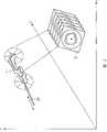
图1示出了光学相干断层造影的基础原理图,Figure 1 shows the basic schematic diagram of optical coherence tomography,
图2是根据本发明的相干断层造影系统的原理图,Fig. 2 is a schematic diagram of a coherence tomography system according to the present invention,
图3示出了根据现有技术的基于二维相干断层造影截面图像进行3D立体再现的原理图。Fig. 3 shows a principle diagram of performing 3D stereo reconstruction based on two-dimensional coherence tomography cross-sectional images according to the prior art.
具体实施方式Detailed ways
图1示出光学相干断层造影的基本原理。从光源(在所示例子中是激光1)向半透镜3上给出光束2。向一个参考臂(Refenzarm)提供第一分光束2a,在该参考臂中例如利用可移动反射镜4调制分光束2a的长度。所调制的反射光到达半透镜3,并通过它作为参考光部分R到达干涉仪5。Figure 1 shows the basic principle of optical coherence tomography. A
另一分光束2b耦合到导管6中,该导管在所示例子中已引入血管7中。在导管6的顶端,耦合的光射出,并旋转着耦合在血管7的组织中。从那里,由于反射中心位置同样被调制(如4个反射光符号8所示),因此反射光重新耦合到导管6中,传导到半透镜3,并从那里同样作为反射的检查光部分U提供给干涉仪5。干涉仪5干涉测量地处理所给出的两个光部分R和U,并确定其相干性。OCT方法本身是公知的,不需要更详细的描述。Another
图2示出根据本发明的光学相干断层造影系统9。该系统包括已描述过的导管10,其由医生例如手动地引入检查对象12的血管11中。在导管的顶端有一个位置传感器13,其构造为电磁发射器,并用于采集在位置采集系统14的坐标系统中用坐标轴x、y和z表示的位置和定向。为此,位置采集系统14在所示例子中具有三个外部接收线圈15x、15y、15z,通过它们一方面分别采集位置传感器13在x、y和z方向上的位置,另一方面分别采集围绕这些轴的、描述位置传感器13的旋转。因此,对一个传感器位置总共采集6个位置数据,即x、y和z以及各围绕这些轴的旋转。FIG. 2 shows an optical coherence tomography system 9 according to the invention. The system includes the
在位置采集系统14的控制装置16中,相应地确定位置数据,并作为位置数据P输出给处理装置17。In the control device 16 of the position detection system 14 the position data are correspondingly determined and output as position data P to the processing device 17 .
如已参照图1所述的,通过与未详细示出的光源连接的导管10,在导管顶端将光旋转着入射到组织中,从而拍摄下二维截面图像S形式的二维环形图像。为了产生该截面图像,由光的入射导致的反射光在导管顶端被扑捉,并通过导管输出,与参考光部分(在图2中未详细示出)一起输出到处理装置17,在那里利用已在图1中描述的干涉仪处理这些信息,并产生二维截面图像或包含图像信息的截面图像数据B。As already described with reference to FIG. 1 , through a
如通过双箭头A所示的,导管沿着血管11移动。在每次伴随着位置传感器13位置变化的移动之后,可以通过位置采集系统14采集每次尚很小的位置或定向变化。合适的是,通过图像拍摄或处理过程的信息这样被触发,即例如仅当位置传感器13移动了一个预定的位移增量(在所提到的6个自由度的至少一个内)后才拍摄二维截面图像,该增量可以通过位置采集系统14清楚地采集。由此可以例如排除,在导管静止时还不间断地拍摄截面图像,或者接着处理为三维再现图像(接着再输入)并由此造成过大的数据量。以下情况也是可以的,即通过这些信息从连续拍摄的截面图像簇中选择用于3D再现的截面图像。该运行方式在本发明中是可变的。As indicated by the double arrow A, the catheter is moved along the
在各种情况下,在处理装置17一侧都有图像数据B和位置数据P,两种数据相互“结合”,也就是对每个二维截面图像或图像数据组分别配置位置数据组。借助这些位置数据和图像数据,在处理装置17一侧进行三维立体再现。在根据对每个截面图像S已知的位置数据而已知一幅截面图像如何关于第二幅截面图像定位或定向之后,可以这样相互相关地设置截面图像或这样再现3D立体,使该3D立体再现血管11的实际几何关系。也就是说,在监视器18上给出的三维再现中,按照其实际的三维形状再现血管11,从而医生可得到体内实际情况的印象。这种可能、即各截面图像按照其相互之间的实际位置排列,在图2中借助相互错开排列的截面图像S表示,虽然这说明根据血管11的实际形状,截面图像当然也可能彼此相对倾斜。In each case, image data B and position data P are present on the side of the processing device 17 , the two data being “combined” with each other, ie a position data set is assigned to each two-dimensional sectional image or image data set. With the aid of these position data and image data, a three-dimensional stereoscopic rendering takes place on the side of the processing device 17 . After knowing how one sectional image is positioned or oriented relative to a second sectional image on the basis of the position data known for each sectional image S, the sectional images can be arranged in relation to each other or the 3D volume can be reproduced in such a way that the 3D volume rendering The actual geometric relationship of the
图2还示出了一种可能性,通过外部触发装置、这里是并行拍摄的EKG(心电图)19,这样进行触发,即只将在同一阶段拍摄的二维截面图像或图像数据组用于3D立体再现。这在血管11例如是心脏冠状血管或类似物时尤其是合适的,从而始终在相同的心脏阶段采集该血管。除了实际上涉及图像处理的该触发之外,当然还可以通过该外部触发,触发与所涉及的待移动的位移增量的数据相关的图像拍摄,该数据由位置采集系统14提供。在这种情况下,图像拍摄仅当已经移动了位移增量并达到各触发阶段时才进行。FIG. 2 also shows a possibility to trigger by means of an external trigger device, here an EKG (electrocardiogram) 19 acquired in parallel, in such a way that only the two-dimensional cross-sectional images or image data sets acquired at the same stage are used for 3D Stereo reproduction. This is especially suitable when the
因此,根据本发明的相干断层造影系统9可以拍摄任意定向的截面图像,并采集其位置数据,分配该位置数据,并根据该数据再现对应于真实情况的立体图像。这还提供一个可能,即在处理装置17一侧例如将二维截面图像相互合并显示在监视器上,其中,对于这些二维图像同样已知位置数据,并且这些位置数据可以唯一地与二维相干断层造影截面图像相对应。为此,例如可以借助在不同数据组中标识的解剖标记,使相干断层造影截面图像和用其它检查模式获得的截面图像相关,以便将待合并的图像相互相关地设置并相互校准。此外还存在一个可能,即在处理装置17一侧将再现的3D立体图像与用其它检查模式拍摄的3D立体图像相组合并一起显示,尤其是,当两个立体数据组是在同一坐标系统内、即位置采集系统14中拍摄的时,由此可以毫不费力地将其相互分配。Therefore, the coherence tomography system 9 according to the present invention can take arbitrarily oriented cross-sectional images, collect their position data, distribute the position data, and reproduce a stereoscopic image corresponding to the real situation according to the data. This also offers the possibility, on the side of the processing device 17, for example to combine two-dimensional cross-sectional images and display them on a monitor, wherein position data are also known for these two-dimensional images and can be uniquely compared with the two-dimensional Corresponding to cross-sectional images of coherence tomography. For this purpose, coherence tomography sectional images and sectional images obtained with other examination modalities can be correlated, for example, with the aid of anatomical markers identified in different data sets, in order to correlate and align the images to be merged. Furthermore, there is a possibility to combine and display the reconstructed 3D volume images with 3D volume images recorded in other examination modes on the side of the processing device 17, especially if the two volume data sets are in the same coordinate system , ie recorded in the position acquisition system 14 , so that they can be assigned to each other without any effort.
图3最后示出了现有技术的缺陷,其中,采用不包含位置传感器的传统导管10’。如果导管在血管11’中移动,则也会拍摄多幅单个截面图像S’,但这些图像在没有位置或定向信息的情况下被相互计算地处理。总之,如图3示例性示出的,在3D立体再现时给出一个直的立体,其根据在任意角度或任意定向下相互排列的截面图像S’再现,该立体与血管11’的实际几何情况不符。也就是说,在此医生获得了对被检查体的错误印象。Fig. 3 finally shows the drawbacks of the prior art, in which a conventional catheter 10' which does not contain a position sensor is used. If the catheter is moved in the blood vessel 11', a plurality of individual sectional images S' are also recorded, but these are processed computationally relative to one another without position or orientation information. In summary, as shown in Figure 3, a straight stereo is given during 3D stereo rendering, which is reproduced from cross-sectional images S' arranged in any angle or orientation, which is consistent with the actual geometry of the blood vessel 11'. The situation does not match. That is to say, here the doctor gets a wrong impression of the examinee.
Claims (5)
Translated fromChineseApplications Claiming Priority (2)
| Application Number | Priority Date | Filing Date | Title |
|---|---|---|---|
| DE10323217.6 | 2003-05-22 | ||
| DE2003123217DE10323217A1 (en) | 2003-05-22 | 2003-05-22 | Optical coherent tomography system of examination of tissues or organs, has position sensor at tip of catheter and reconstructs volume image based on sectional images and associated position data |
Publications (2)
| Publication Number | Publication Date |
|---|---|
| CN1572248A CN1572248A (en) | 2005-02-02 |
| CN100457035Ctrue CN100457035C (en) | 2009-02-04 |
Family
ID=33441163
Family Applications (1)
| Application Number | Title | Priority Date | Filing Date |
|---|---|---|---|
| CNB2004100459004AExpired - Fee RelatedCN100457035C (en) | 2003-05-22 | 2004-05-24 | Optical coherence tomography system for the examination of human or animal tissue or of organs |
Country Status (3)
| Country | Link |
|---|---|
| US (1) | US7406346B2 (en) |
| CN (1) | CN100457035C (en) |
| DE (1) | DE10323217A1 (en) |
Families Citing this family (86)
| Publication number | Priority date | Publication date | Assignee | Title |
|---|---|---|---|---|
| CA2595324C (en)* | 2005-01-21 | 2015-08-11 | Massachusetts Institute Of Technology | Methods and apparatus for optical coherence tomography scanning |
| DE102005044889A1 (en)* | 2005-09-20 | 2007-03-29 | Siemens Ag | Dental examination and / or treatment work train |
| DE102005022345A1 (en)* | 2005-05-13 | 2006-11-16 | Siemens Ag | Method for creation of image of vessel and obtaining information about speed of blood flow, comprises use of ultrasonic catheter |
| DE102005029897A1 (en)* | 2005-06-27 | 2007-01-04 | Siemens Ag | Picture giving procedure with optical coherence tomography catheter for visualizing molecular functional processes in vulnerable plaques of a blood vessel of a patient, comprises producing tomography picture of contrast agent-marked plaque |
| DE102005037427A1 (en)* | 2005-08-08 | 2007-02-15 | Siemens Ag | Method for recording and evaluating vascular examination data |
| JP4916779B2 (en)* | 2005-09-29 | 2012-04-18 | 株式会社トプコン | Fundus observation device |
| US8135453B2 (en)* | 2005-12-07 | 2012-03-13 | Siemens Corporation | Method and apparatus for ear canal surface modeling using optical coherence tomography imaging |
| US8538508B2 (en)* | 2005-12-09 | 2013-09-17 | Siemens Aktiengesellschaft | Method and apparatus for ECG-synchronized optically-based image acquisition and transformation |
| JP4823693B2 (en)* | 2006-01-11 | 2011-11-24 | 株式会社トプコン | Optical image measuring device |
| US8184367B2 (en)* | 2006-02-15 | 2012-05-22 | University Of Central Florida Research Foundation | Dynamically focused optical instrument |
| US20070232883A1 (en)* | 2006-02-15 | 2007-10-04 | Ilegbusi Olusegun J | Systems and methods for determining plaque vulnerability to rupture |
| US7996059B2 (en)* | 2006-03-08 | 2011-08-09 | Biosense Webster, Inc. | Esophagus imaging enhancement device |
| JP4268976B2 (en)* | 2006-06-15 | 2009-05-27 | ジーイー・メディカル・システムズ・グローバル・テクノロジー・カンパニー・エルエルシー | Imaging device |
| DE102006050886B4 (en)* | 2006-10-27 | 2016-12-22 | Siemens Healthcare Gmbh | Medical instrument and device for generating tissue sections |
| DE102006050885B4 (en) | 2006-10-27 | 2016-11-03 | Siemens Healthcare Gmbh | Device for generating tissue section images |
| CN107126182B (en)* | 2007-01-19 | 2020-06-16 | 桑尼布鲁克健康科学中心 | Scanning mechanism for imaging probe |
| EP2160217A1 (en)* | 2007-06-08 | 2010-03-10 | Prescient Medical, Inc. | Optical catheter configurations combining raman spectroscopy with optical fiber-based low coherence reflectometry |
| US20090024040A1 (en)* | 2007-07-20 | 2009-01-22 | Prescient Medical, Inc. | Wall-Contacting Intravascular Ultrasound Probe Catheters |
| US9788790B2 (en)* | 2009-05-28 | 2017-10-17 | Avinger, Inc. | Optical coherence tomography for biological imaging |
| US8696695B2 (en) | 2009-04-28 | 2014-04-15 | Avinger, Inc. | Guidewire positioning catheter |
| US9125562B2 (en) | 2009-07-01 | 2015-09-08 | Avinger, Inc. | Catheter-based off-axis optical coherence tomography imaging system |
| US8062316B2 (en) | 2008-04-23 | 2011-11-22 | Avinger, Inc. | Catheter system and method for boring through blocked vascular passages |
| US20100113906A1 (en)* | 2008-11-06 | 2010-05-06 | Prescient Medical, Inc. | Hybrid basket catheters |
| EP2226003B1 (en)* | 2009-03-05 | 2015-05-06 | Brainlab AG | Medical image registration by means of optical coherence tomography |
| WO2011003006A2 (en) | 2009-07-01 | 2011-01-06 | Avinger, Inc. | Atherectomy catheter with laterally-displaceable tip |
| WO2011072068A2 (en) | 2009-12-08 | 2011-06-16 | Avinger, Inc. | Devices and methods for predicting and preventing restenosis |
| JP2013534841A (en) | 2010-06-13 | 2013-09-09 | アンジオメトリックス コーポレーション | Diagnostic kit and method for measuring balloon dimensions in vivo |
| US11382653B2 (en) | 2010-07-01 | 2022-07-12 | Avinger, Inc. | Atherectomy catheter |
| US10548478B2 (en) | 2010-07-01 | 2020-02-04 | Avinger, Inc. | Balloon atherectomy catheters with imaging |
| WO2014039096A1 (en) | 2012-09-06 | 2014-03-13 | Avinger, Inc. | Re-entry stylet for catheter |
| US9345510B2 (en) | 2010-07-01 | 2016-05-24 | Avinger, Inc. | Atherectomy catheters with longitudinally displaceable drive shafts |
| US9949754B2 (en) | 2011-03-28 | 2018-04-24 | Avinger, Inc. | Occlusion-crossing devices |
| EP2691038B1 (en) | 2011-03-28 | 2016-07-20 | Avinger, Inc. | Occlusion-crossing devices, imaging, and atherectomy devices |
| EP2551698B1 (en)* | 2011-07-29 | 2014-09-17 | Richard Wolf GmbH | Endoscopic instrument |
| EP3653151A1 (en) | 2011-10-17 | 2020-05-20 | Avinger, Inc. | Atherectomy catheters and non-contact actuation mechanism for catheters |
| US9345406B2 (en) | 2011-11-11 | 2016-05-24 | Avinger, Inc. | Occlusion-crossing devices, atherectomy devices, and imaging |
| JP2015514494A (en)* | 2012-04-17 | 2015-05-21 | カレッジ メディカル イメージング リミテッド | Organ mapping system using optical coherence tomography probe |
| US9557156B2 (en) | 2012-05-14 | 2017-01-31 | Avinger, Inc. | Optical coherence tomography with graded index fiber for biological imaging |
| EP2849660B1 (en) | 2012-05-14 | 2021-08-25 | Avinger, Inc. | Atherectomy catheter drive assemblies |
| WO2013172970A1 (en) | 2012-05-14 | 2013-11-21 | Avinger, Inc. | Atherectomy catheters with imaging |
| US9498247B2 (en) | 2014-02-06 | 2016-11-22 | Avinger, Inc. | Atherectomy catheters and occlusion crossing devices |
| US11284916B2 (en) | 2012-09-06 | 2022-03-29 | Avinger, Inc. | Atherectomy catheters and occlusion crossing devices |
| WO2014106137A1 (en)* | 2012-12-28 | 2014-07-03 | The General Hospital Corporation | Optical probe apparatus, systems, methods for guiding tissue asessment |
| CN105228514B (en) | 2013-03-15 | 2019-01-22 | 阿维格公司 | Optical Pressure Sensor Assembly |
| WO2014143064A1 (en) | 2013-03-15 | 2014-09-18 | Avinger, Inc. | Chronic total occlusion crossing devices with imaging |
| US11096717B2 (en) | 2013-03-15 | 2021-08-24 | Avinger, Inc. | Tissue collection device for catheter |
| EP3019096B1 (en) | 2013-07-08 | 2023-07-05 | Avinger, Inc. | System for identification of elastic lamina to guide interventional therapy |
| MX2016010141A (en) | 2014-02-06 | 2017-04-06 | Avinger Inc | Atherectomy catheters and occlusion crossing devices. |
| US10357277B2 (en) | 2014-07-08 | 2019-07-23 | Avinger, Inc. | High speed chronic total occlusion crossing devices |
| US20160007854A1 (en)* | 2014-07-09 | 2016-01-14 | Physical Sciences, Inc. | Apparatus and Method for Assessment of Interstitial Tissue |
| US10952601B2 (en) | 2015-05-08 | 2021-03-23 | Photonicare, Inc. | Otoscope tip and methods of use |
| WO2016182999A1 (en) | 2015-05-08 | 2016-11-17 | Photonicare, Inc. | Otoscope tip and methods of use |
| US10568520B2 (en) | 2015-07-13 | 2020-02-25 | Avinger, Inc. | Micro-molded anamorphic reflector lens for image guided therapeutic/diagnostic catheters |
| JP6927986B2 (en) | 2016-01-25 | 2021-09-01 | アビンガー・インコーポレイテッドAvinger, Inc. | OCT imaging catheter with delay compensation |
| EP3435892B1 (en) | 2016-04-01 | 2024-04-03 | Avinger, Inc. | Atherectomy catheter with serrated cutter |
| US11344327B2 (en) | 2016-06-03 | 2022-05-31 | Avinger, Inc. | Catheter device with detachable distal end |
| WO2018006041A1 (en) | 2016-06-30 | 2018-01-04 | Avinger, Inc. | Atherectomy catheter with shapeable distal tip |
| EP3323565B1 (en)* | 2016-11-21 | 2021-06-30 | Siemens Aktiengesellschaft | Method and device for commissioning a multiple axis system |
| EP3606592B1 (en) | 2017-04-07 | 2025-01-08 | Bard Access Systems, Inc. | Optical fiber-based medical device tracking and monitoring system |
| RU179037U1 (en)* | 2017-12-13 | 2018-04-25 | Федеральное государственное бюджетное образовательное учреждение высшего образования "Тамбовский государственный технический университет" (ФГБОУ ВО "ТГТУ") | Endoscopic optical coherence tomography device |
| CN107966823B (en)* | 2017-12-28 | 2024-07-30 | 河南科技大学第一附属医院 | CT planar image three-dimensional conversion device and focus positioning method |
| US12167867B2 (en) | 2018-04-19 | 2024-12-17 | Avinger, Inc. | Occlusion-crossing devices |
| EP4013338A4 (en) | 2019-08-12 | 2023-08-30 | Bard Access Systems, Inc. | SHAPE DETECTION SYSTEMS AND METHODS FOR MEDICAL DEVICES |
| CN114746033B (en) | 2019-10-18 | 2025-01-10 | 阿维格公司 | Blocking crossing device |
| CN112826497B (en) | 2019-11-25 | 2025-09-09 | 巴德阿克塞斯系统股份有限公司 | Optical tip tracking system and method thereof |
| EP4061272A4 (en) | 2019-11-25 | 2023-11-22 | Bard Access Systems, Inc. | Shape-sensing systems with filters and methods thereof |
| CN215461207U (en) | 2020-02-28 | 2022-01-11 | 巴德阿克塞斯系统股份有限公司 | Catheter and medical instrument monitoring system |
| US11474310B2 (en) | 2020-02-28 | 2022-10-18 | Bard Access Systems, Inc. | Optical connection systems and methods thereof |
| CN113332561A (en) | 2020-03-03 | 2021-09-03 | 巴德阿克塞斯系统股份有限公司 | System and method for optical shape sensing and electrical signal conduction |
| WO2021202589A1 (en) | 2020-03-30 | 2021-10-07 | Bard Access Systems, Inc. | Optical and electrical diagnostic systems and methods thereof |
| CN113842536A (en) | 2020-06-26 | 2021-12-28 | 巴德阿克塞斯系统股份有限公司 | Dislocation detection system |
| WO2022005870A1 (en) | 2020-06-29 | 2022-01-06 | Bard Access Systems, Inc. | Automatic dimensional frame reference for fiber optic |
| WO2022011287A1 (en) | 2020-07-10 | 2022-01-13 | Bard Access Systems, Inc. | Continuous fiber optic functionality monitoring and self-diagnostic reporting system |
| WO2022031613A1 (en) | 2020-08-03 | 2022-02-10 | Bard Access Systems, Inc. | Bragg grated fiber optic fluctuation sensing and monitoring system |
| CN114246583A (en) | 2020-09-25 | 2022-03-29 | 巴德阿克塞斯系统股份有限公司 | Fiber Optic Oximetry Systems for Detection and Confirmation |
| CN114344514A (en) | 2020-10-13 | 2022-04-15 | 巴德阿克塞斯系统股份有限公司 | Disinfection enclosure for fiber optic connectors and method thereof |
| CN114518075A (en) | 2020-11-18 | 2022-05-20 | 巴德阿克塞斯系统股份有限公司 | fiber optic stylet holder |
| WO2022115624A1 (en) | 2020-11-24 | 2022-06-02 | Bard Access Systems, Inc. | Steerable fiber optic shape sensing enabled elongated medical instrument |
| WO2022150411A1 (en) | 2021-01-06 | 2022-07-14 | Bard Access Systems, Inc. | Needle guidance using fiber optic shape sensing |
| US12426954B2 (en) | 2021-01-26 | 2025-09-30 | Bard Access Systems, Inc. | Fiber optic shape sensing system associated with port placement |
| US12419694B2 (en) | 2021-10-25 | 2025-09-23 | Bard Access Systems, Inc. | Reference plane for medical device placement |
| US12318149B2 (en) | 2022-03-08 | 2025-06-03 | Bard Access Systems, Inc. | Medical shape sensing devices and systems |
| US12426956B2 (en) | 2022-03-16 | 2025-09-30 | Bard Access Systems, Inc. | Medical system and method for monitoring medical device insertion and illumination patterns |
| US12089815B2 (en) | 2022-03-17 | 2024-09-17 | Bard Access Systems, Inc. | Fiber optic medical systems and devices with atraumatic tip |
| US12343117B2 (en) | 2022-06-28 | 2025-07-01 | Bard Access Systems, Inc. | Fiber optic medical systems and methods for identifying blood vessels |
| US12349984B2 (en) | 2022-06-29 | 2025-07-08 | Bard Access Systems, Inc. | System, method, and apparatus for improved confirm of an anatomical position of a medical instrument |
Citations (7)
| Publication number | Priority date | Publication date | Assignee | Title |
|---|---|---|---|---|
| US5795295A (en)* | 1996-06-25 | 1998-08-18 | Carl Zeiss, Inc. | OCT-assisted surgical microscope with multi-coordinate manipulator |
| US5921926A (en)* | 1997-07-28 | 1999-07-13 | University Of Central Florida | Three dimensional optical imaging colposcopy |
| EP0961135A1 (en)* | 1998-03-30 | 1999-12-01 | TomTec Imaging Systems GmbH | Method and apparatus for ultrasound image acquisition |
| US6175669B1 (en)* | 1998-03-30 | 2001-01-16 | The Regents Of The Universtiy Of California | Optical coherence domain reflectometry guidewire |
| US20020049375A1 (en)* | 1999-05-18 | 2002-04-25 | Mediguide Ltd. | Method and apparatus for real time quantitative three-dimensional image reconstruction of a moving organ and intra-body navigation |
| US20030032878A1 (en)* | 1996-06-28 | 2003-02-13 | The Board Of Trustees Of The Leland Stanford Junior University | Method and apparatus for volumetric image navigation |
| US6527708B1 (en)* | 1999-07-02 | 2003-03-04 | Pentax Corporation | Endoscope system |
Family Cites Families (4)
| Publication number | Priority date | Publication date | Assignee | Title |
|---|---|---|---|---|
| US5830145A (en)* | 1996-09-20 | 1998-11-03 | Cardiovascular Imaging Systems, Inc. | Enhanced accuracy of three-dimensional intraluminal ultrasound (ILUS) image reconstruction |
| US5752518A (en)* | 1996-10-28 | 1998-05-19 | Ep Technologies, Inc. | Systems and methods for visualizing interior regions of the body |
| DE29809604U1 (en) | 1998-05-28 | 1999-07-15 | Seba-Dynatronic Mess- und Ortungstechnik GmbH, 96148 Baunach | Device for phase identification of the phase assignment of medium-voltage cables |
| DE10051244A1 (en)* | 2000-10-17 | 2002-05-16 | Philips Corp Intellectual Pty | X-ray free intravascular localization and imaging procedure |
- 2003
- 2003-05-22DEDE2003123217patent/DE10323217A1/ennot_activeWithdrawn
- 2004
- 2004-05-21USUS10/851,936patent/US7406346B2/enactiveActive
- 2004-05-24CNCNB2004100459004Apatent/CN100457035C/ennot_activeExpired - Fee Related
Patent Citations (7)
| Publication number | Priority date | Publication date | Assignee | Title |
|---|---|---|---|---|
| US5795295A (en)* | 1996-06-25 | 1998-08-18 | Carl Zeiss, Inc. | OCT-assisted surgical microscope with multi-coordinate manipulator |
| US20030032878A1 (en)* | 1996-06-28 | 2003-02-13 | The Board Of Trustees Of The Leland Stanford Junior University | Method and apparatus for volumetric image navigation |
| US5921926A (en)* | 1997-07-28 | 1999-07-13 | University Of Central Florida | Three dimensional optical imaging colposcopy |
| EP0961135A1 (en)* | 1998-03-30 | 1999-12-01 | TomTec Imaging Systems GmbH | Method and apparatus for ultrasound image acquisition |
| US6175669B1 (en)* | 1998-03-30 | 2001-01-16 | The Regents Of The Universtiy Of California | Optical coherence domain reflectometry guidewire |
| US20020049375A1 (en)* | 1999-05-18 | 2002-04-25 | Mediguide Ltd. | Method and apparatus for real time quantitative three-dimensional image reconstruction of a moving organ and intra-body navigation |
| US6527708B1 (en)* | 1999-07-02 | 2003-03-04 | Pentax Corporation | Endoscope system |
Non-Patent Citations (4)
| Title |
|---|
| 3D Navigation for Endoscope by Magnetic Field. Liu X. Y., Chen X., Lin D., etc.SPIE,Vol.4556 . 2001 |
| 3D Navigation for Endoscope by Magnetic Field. Liu X. Y., Chen X., Lin D., etc.SPIE,Vol.4556 . 2001* |
| Three-dimesional reconstruction of rat dermal blood vessels invivo. Jennifer K. B., Joseph A. I., Manish D. K., etc.SPIE,Vol.2970 . 1997 |
| Three-dimesional reconstruction of rat dermal blood vessels invivo. Jennifer K. B., Joseph A. I., Manish D. K., etc.SPIE,Vol.2970 . 1997* |
Also Published As
| Publication number | Publication date |
|---|---|
| CN1572248A (en) | 2005-02-02 |
| DE10323217A1 (en) | 2004-12-16 |
| US7406346B2 (en) | 2008-07-29 |
| US20050020925A1 (en) | 2005-01-27 |
Similar Documents
| Publication | Publication Date | Title |
|---|---|---|
| CN100457035C (en) | Optical coherence tomography system for the examination of human or animal tissue or of organs | |
| US6628977B2 (en) | Method and system for visualizing an object | |
| US9775538B2 (en) | System and method for determining the position of the tip of a medical catheter within the body of a patient | |
| US7343195B2 (en) | Method and apparatus for real time quantitative three-dimensional image reconstruction of a moving organ and intra-body navigation | |
| US8457375B2 (en) | Visualization method and imaging system | |
| JP4993982B2 (en) | Catheter apparatus and treatment apparatus | |
| CN100553550C (en) | The pipe guide that comprises conduit, especially catheter in blood vessel | |
| CN1977765B (en) | Method and apparatus for ECG-synchronized optically-based image acquisition and transformation | |
| US9747689B2 (en) | Image processing system, X-ray diagnostic apparatus, and image processing method | |
| US20030181809A1 (en) | 3D imaging for catheter interventions by use of 2D/3D image fusion | |
| JP2009532162A (en) | Determining the tissue surrounding an object inserted in a patient | |
| JP2003305032A (en) | Method for detecting and rendering a medical catheter introduced in an examination area of a patient | |
| JP2005253964A (en) | Intraluminal image forming method | |
| JP2001061861A (en) | System and medical workstation with image capturing means | |
| MX2007015573A (en) | Coloring electroanatomical maps to indicate ultrasound data acquisition. | |
| JP2002083281A (en) | Imaging device for displaying volume with high quality by real-time three-dimensional reconstruction, and method therefor | |
| JP2004121840A (en) | Method for forming a CT image of a periodically moving organ and a CT apparatus for implementing the method | |
| JP2010094181A (en) | Ultrasonic diagnostic apparatus and data processing program of the same | |
| JP2025128114A (en) | Combined imaging system and method | |
| JP6100911B2 (en) | Diagnostic imaging apparatus and operating method thereof | |
| JP2000166927A (en) | Three-dimensional imaging device | |
| US20090076386A1 (en) | Method and system for acquiring volume of interest based on positional information | |
| US20050148853A1 (en) | Method for supporting navigation of a medical instrument, in particular of a catheter | |
| Maurincomme et al. | What are the advantages and limitations of three-dimensional intracoronary ultrasound imaging? | |
| JP5921610B2 (en) | Ultrasonic diagnostic equipment |
Legal Events
| Date | Code | Title | Description |
|---|---|---|---|
| C06 | Publication | ||
| PB01 | Publication | ||
| C10 | Entry into substantive examination | ||
| SE01 | Entry into force of request for substantive examination | ||
| C14 | Grant of patent or utility model | ||
| GR01 | Patent grant | ||
| CF01 | Termination of patent right due to non-payment of annual fee | ||
| CF01 | Termination of patent right due to non-payment of annual fee | Granted publication date:20090204 Termination date:20200524 |