Movatterモバイル変換


[0]ホーム

URL:


CN100454211C - Display with rotatable image acquisition assembly - Google Patents

Display with rotatable image acquisition assembly
Download PDF

Info

Publication number
CN100454211C
CN100454211CCNB2005100047475ACN200510004747ACN100454211CCN 100454211 CCN100454211 CCN 100454211CCN B2005100047475 ACNB2005100047475 ACN B2005100047475ACN 200510004747 ACN200510004747 ACN 200510004747ACN 100454211 CCN100454211 CCN 100454211C
Authority
CN
China
Prior art keywords
casing
cam
image capture
display
sleeve
Prior art date
Legal status (The legal status is an assumption and is not a legal conclusion. Google has not performed a legal analysis and makes no representation as to the accuracy of the status listed.)
Expired - Lifetime
Application number
CNB2005100047475A
Other languages
Chinese (zh)
Other versions
CN1808329A (en
Inventor
王顺隆
李益全
Current Assignee (The listed assignees may be inaccurate. Google has not performed a legal analysis and makes no representation or warranty as to the accuracy of the list.)
Asustek Computer Inc
Original Assignee
Asustek Computer Inc
Priority date (The priority date is an assumption and is not a legal conclusion. Google has not performed a legal analysis and makes no representation as to the accuracy of the date listed.)
Filing date
Publication date
Application filed by Asustek Computer IncfiledCriticalAsustek Computer Inc
Priority to CNB2005100047475ApriorityCriticalpatent/CN100454211C/en
Publication of CN1808329ApublicationCriticalpatent/CN1808329A/en
Application grantedgrantedCritical
Publication of CN100454211CpublicationCriticalpatent/CN100454211C/en
Anticipated expirationlegal-statusCritical
Expired - Lifetimelegal-statusCriticalCurrent

Links

Images

Landscapes

Abstract

A display includes a first housing, a display panel and an image capturing assembly. The first casing has a first surface and a second surface opposite to each other, and the display panel is disposed on the first surface. The image capturing assembly comprises a second shell and an image capturing unit. The second shell is fixedly connected to the first shell and provided with an opening, and the opening penetrates through the first surface and the second surface. Two ends of the image capturing unit are respectively pivoted on the opening wall of the opening, so that the image capturing component is rotatably arranged on the display.

Description

Translated fromChinese
具有可旋转的影像撷取组件的显示器Display with rotatable image capture assembly

技术领域technical field

本发明有关一种显示器,且特别是有关于一种具有可旋转的影像撷取组件的显示器。The present invention relates to a display, and more particularly to a display with a rotatable image capturing component.

背景技术Background technique

随着可携式信息产品、3G宽频与信息家电产业的蓬勃发展,搭配动态影音撷取与实时视讯等新兴多媒体应用,预期未来将有令人瞩目的市场潜力。With the vigorous development of portable information products, 3G broadband and information home appliance industry, together with new multimedia applications such as dynamic video capture and real-time video, it is expected that there will be impressive market potential in the future.

请参照图1A,其是依照传统具有镜头组件的笔记本电脑于展开时的立体图。传统笔记本电脑10至少包括本体11、上盖12、显示面板13以及镜头组件20。上盖12枢接于本体11,显示面板13设置于上盖12。镜头组件20包括一壳体21以及一镜头(CMOS camera)22,镜头组件20是以可旋转的方式设置于上盖12,并位于显示面板13的上方。当使用时,镜头22是以旋转方式调整角度,以撷取与使用者所视需的影像画面;当收纳时,镜头22旋转至与显示面板13共平面,以保护镜头20,如图1A所示。将镜头组件内建于笔记本电脑中,可充份发挥笔记本电脑轻巧、便利、可移动性的功能,例如是使用者可随时随地召开视讯会议,让声音与影像同步的沟通完全不受空间的限制。Please refer to FIG. 1A , which is a perspective view of a conventional notebook computer with a lens assembly when unfolded. Theconventional notebook computer 10 at least includes amain body 11 , atop cover 12 , adisplay panel 13 and alens assembly 20 . Theupper cover 12 is pivotally connected to themain body 11 , and thedisplay panel 13 is disposed on theupper cover 12 . Thelens assembly 20 includes ahousing 21 and a lens (CMOS camera) 22. Thelens assembly 20 is rotatably arranged on theupper cover 12 and located above thedisplay panel 13. When in use, thelens 22 is rotated to adjust the angle, so as to capture the image frame required by the user; when stored, thelens 22 is rotated to be coplanar with thedisplay panel 13 to protect thelens 20, as shown in FIG. 1A Show. The lens assembly is built into the notebook computer, which can give full play to the lightness, convenience, and mobility of the notebook computer. For example, users can hold video conferences anytime and anywhere, so that the simultaneous communication of audio and video is completely free from space constraints. .

然而,传统笔记本电脑的镜头组件是设置于上盖的边缘,极易碰撞而造成损坏。请参照图1B,其是依照图1A中的笔记本电脑于阖上时的前视图。再者,使用者于开阖上盖12时极易碰触到镜头组件20,而造成镜头组件20不必要的翻转。当使用者手持上盖12的一端以打开上盖12的同时,即便使用者不想使用镜头组件,镜头组件20也极易被触碰而翻转向外。同理,不论是打开或关闭上盖12时,使用者皆会碰触到镜头组件20而造成不必要的作动,常此以往,镜头组件20不仅容易造成松脱损坏,更会缩短其机械构件的使用年限。However, the lens assembly of the traditional notebook computer is arranged on the edge of the upper cover, which is very easy to be damaged due to collision. Please refer to FIG. 1B , which is a front view of the laptop computer according to FIG. 1A when it is closed. Furthermore, the user easily touches thelens assembly 20 when opening and closing theupper cover 12 , causing thelens assembly 20 to turn over unnecessarily. When the user holds one end of theupper cover 12 to open theupper cover 12 , even if the user does not want to use the lens assembly, thelens assembly 20 is easily touched and turned outward. In the same way, no matter when opening or closing theupper cover 12, the user will touch thelens assembly 20 and cause unnecessary movement. In the past, thelens assembly 20 is not only easy to cause loose damage, but also shortens its mechanical function. The useful life of the component.

发明内容Contents of the invention

本发明的一目的是提供一种显示器,其影像撷取组件具有保护外壳的设计,可避免不必要的翻转动作与碰撞。An object of the present invention is to provide a display, the image capturing component of which has a protective shell design, which can avoid unnecessary flipping and collision.

本发明的另一目的是提供一种显示器,其影像撷取组件是采用二段式旋转的设计,使得影像撷取组件可固定于几组特定角度与位置上,以便利使用者使用与收纳影像撷取组件。Another object of the present invention is to provide a display, the image capture component of which adopts a two-stage rotating design, so that the image capture component can be fixed at several specific angles and positions, so as to facilitate the use and storage of images by users Fetch components.

根据本发明一方面的一种显示器,包括第一壳体、显示面板以及影像撷取组件。第一壳体具有相对的一第一表面与一第二表面,显示面板设置于第一表面。影像撷取组件包括第二壳体与影像撷取单元。第二壳体固接于第一壳体,第二壳体具有一开口,开口贯穿第一表面与第二表面。影像撷取单元,其二端分别枢接于开口的口壁,借此,影像撷取单元以可旋转的方式设置于第二壳体。A display according to one aspect of the present invention includes a first casing, a display panel, and an image capturing component. The first casing has a first surface and a second surface opposite to each other, and the display panel is disposed on the first surface. The image capture component includes a second casing and an image capture unit. The second casing is fixedly connected to the first casing. The second casing has an opening, and the opening passes through the first surface and the second surface. The two ends of the image capture unit are respectively pivotally connected to the mouth wall of the opening, whereby the image capture unit is rotatably arranged on the second casing.

根据本发明另一方面的一种显示器,包括:第一壳体、显示面板以及影像撷取组件。第一壳体具有相对的一第一表面与一第二表面,显示面板设置于第一表面。影像撷取组件贯穿第一表面与第二表面,其包括第二壳体与影像撷取单元。影像撷取单元是以可旋转的方式设置于显示器,并是选择性地定位于一第一位置与一第二位置;其中,该影像撷取单元位于该开口中,且该影像撷取单元的二端分别枢接于该开口的口壁,借此,该影像撷取单元是以可旋转的方式设置于该第二壳体;当影像撷取单元旋转至第一位置时,影像撷取单元的一前表面是与第一表面共平面,当影像撷取单元旋转至一第二位置时,影像撷取单元的前表面是与显示面板共平面。A display according to another aspect of the present invention includes: a first casing, a display panel, and an image capturing component. The first casing has a first surface and a second surface opposite to each other, and the display panel is disposed on the first surface. The image capture component runs through the first surface and the second surface, and includes a second casing and an image capture unit. The image capture unit is rotatably arranged on the display, and is selectively positioned at a first position and a second position; wherein, the image capture unit is located in the opening, and the image capture unit The two ends are respectively pivotally connected to the mouth wall of the opening, whereby the image capture unit is rotatably arranged on the second casing; when the image capture unit rotates to the first position, the image capture unit A front surface of the image capture unit is coplanar with the first surface, and when the image capture unit rotates to a second position, the front surface of the image capture unit is coplanar with the display panel.

根据本发明又一发明的一种影像撷取组件,用以设置于一显示器中,该显示器包括一显示面板以及一第一壳体,该第一壳体具有相对的一第一表面以及一第二表面,该显示面板设置于该第一表面。该影像撷取组件包括:一第二壳体和一影像撷取单元。第二壳体固接于该第一壳体,具有一开口,该开口贯穿一第一表面与一第二表面;影像撷取单元,包括:一第三壳体、一镜头以及一枢轴。镜头设置于该第三壳体。枢轴凸设于该第三壳体的一第一侧,并以可转动的方式卡接于该第二壳体,借此,该第三壳体与该镜头是以该枢轴为一转动轴相对该第二壳体转动。An image capture component according to still another invention of the present invention is used to be arranged in a display, and the display includes a display panel and a first casing, and the first casing has a first opposite surface and a first casing. Two surfaces, the display panel is disposed on the first surface. The image capture component includes: a second casing and an image capture unit. The second casing is fixedly connected to the first casing and has an opening, and the opening runs through a first surface and a second surface; the image capture unit includes: a third casing, a lens and a pivot. The lens is arranged on the third casing. The pivot is protrudingly arranged on a first side of the third casing, and is rotatably engaged with the second casing, whereby the third casing and the lens rotate around the pivot The shaft rotates relative to the second housing.

为让本发明的上述目的、特点和优点能更明显易懂,下文特举一较佳实施例,并配合附图进行详细说明如下:In order to make the above-mentioned purposes, features and advantages of the present invention more comprehensible, a preferred embodiment is specifically cited below, and is described in detail in conjunction with the accompanying drawings as follows:

附图说明Description of drawings

图1A是依照传统的具有镜头组件的笔记本电脑于展开时的立体图。FIG. 1A is a perspective view of a conventional notebook computer with a lens assembly when unfolded.

图1B是依照图1A中的笔记本电脑于阖上时的前视图。FIG. 1B is a front view of the notebook computer according to FIG. 1A when it is closed.

图2是依照本发明一较佳实施例的具有显示器的笔记本电脑的一种立体图。FIG. 2 is a perspective view of a notebook computer with a display according to a preferred embodiment of the present invention.

图3A是依照本实施例的显示器的影像撷取组件的俯视图。FIG. 3A is a top view of the image capturing component of the display according to the present embodiment.

图3B是依照本实施例的显示器的影像撷取组件的俯视图。FIG. 3B is a top view of the image capturing component of the display according to the present embodiment.

图3C是依照本实施例的显示器的影像撷取组件的俯视图。FIG. 3C is a top view of the image capturing component of the display according to the present embodiment.

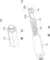
图4是本实施例的显示器的影像撷取组件的立体分解图。FIG. 4 is an exploded perspective view of the image capturing component of the display of this embodiment.

图5A是依照图4中影像撷取组件的分段旋转组件的立体图。FIG. 5A is a perspective view of a segmented rotation assembly according to the image capture assembly in FIG. 4 .

图5B是依照图5A中影像撷取组件的分段旋转组件的立体分解图。FIG. 5B is an exploded perspective view of the segmented rotation assembly according to the image capture assembly in FIG. 5A .

图6A是本实施例的显示器的影像撷取单元于第一位置时的立体图。FIG. 6A is a perspective view of the image capture unit of the display in the present embodiment when it is at a first position.

图6B是本实施例的显示器的影像撷取单元由第一位置旋转至第二位置时的立体图。FIG. 6B is a perspective view of the image capturing unit of the display in this embodiment when it is rotated from the first position to the second position.

图6C是本实施例的显示器的影像撷取单元于第二位置时的立体图。FIG. 6C is a perspective view of the image capturing unit of the display in the present embodiment when it is in the second position.

具体实施方式Detailed ways

本发明的主要构想是提出一种具有可旋转的影像撷取组件的显示器,其具有保护外壳的设计,可避免于开阖时对影像撷取单元产生不必要的移动与破坏。其中,本发明的影像撷取组件包括第二壳体与影像撷取单元。第二壳体是固接于显示器的第一壳体,且第二壳体具有一开口。影像撷取单元的二端是分别枢接于开口的口壁,借此,影像撷取单元是以可旋转的方式设置于显示器中。The main idea of the present invention is to provide a display with a rotatable image capture unit, which has a protective shell design, which can avoid unnecessary movement and damage to the image capture unit when opening and closing. Wherein, the image capture component of the present invention includes a second casing and an image capture unit. The second casing is fixedly connected to the first casing of the display, and the second casing has an opening. The two ends of the image capture unit are respectively pivotally connected to the mouth wall of the opening, whereby the image capture unit is rotatably arranged in the display.

本发明的主要构想是提出一种可旋转的影像撷取组件,其二段式定位的设计,使得影像撷取组件是可固定于几组特定角度与位置上,以便利使用者使用与收纳影像撷取组件。其中,本发明的影像撷取组件是以可旋转的方式设置于显示器,并是选择性地定位于一第一位置与一第二位置;其中,当影像撷取组件旋转至第一位置时,影像撷取组件的前表面是与第一表面共平面,当影像撷取组件旋转至一第二位置时,影像撷取组件的前表面是与显示面板共平面。The main idea of the present invention is to propose a rotatable image capture unit. Its two-stage positioning design allows the image capture unit to be fixed at several specific angles and positions, so as to facilitate the use and storage of images by users. Fetch components. Wherein, the image capture component of the present invention is arranged on the display in a rotatable manner, and is selectively positioned at a first position and a second position; wherein, when the image capture component rotates to the first position, The front surface of the image capture component is coplanar with the first surface, and when the image capture component rotates to a second position, the front surface of the image capture component is coplanar with the display panel.

以下是举一笔记本电脑为例作详细说明,然而本实施例仅为本发明的发明精神下的一种实施方式,并不会对本发明的欲保护范围进行限缩。A notebook computer is taken as an example to describe in detail below. However, this embodiment is only an implementation mode under the inventive spirit of the present invention, and does not limit the intended protection scope of the present invention.

请参照图2,其是依照本发明一较佳实施例的具有显示器的笔记本电脑的一种立体图。本实施例的显示器,例如是液晶显示面板,是设置于一笔记本电脑中。本实施例的显示器100包括第一壳体110、显示面板(未显示)以及影像撷取组件120。第一壳体110有相对的一第一表面(未显示)与一第二表面112,显示面板设置于第一表面。影像撷取组件120包括第二壳体122与影像撷取单元130,第二壳体122固接于第一壳体110。较佳的是,第二壳体凸出于第一壳体的边缘,并高于第一表面。如此一来,当使用者开阖第一壳体时,不会触碰到影像撷取单元,避免不必要的旋转,可延长机械组件的使用寿命。Please refer to FIG. 2 , which is a perspective view of a notebook computer with a display according to a preferred embodiment of the present invention. The display of this embodiment, such as a liquid crystal display panel, is set in a notebook computer. Thedisplay 100 of this embodiment includes afirst housing 110 , a display panel (not shown) and animage capturing component 120 . Thefirst housing 110 has a first surface (not shown) and asecond surface 112 opposite to each other, and the display panel is disposed on the first surface. Theimage capturing component 120 includes asecond casing 122 and animage capturing unit 130 , and thesecond casing 122 is fixedly connected to thefirst casing 110 . Preferably, the second casing protrudes from the edge of the first casing and is higher than the first surface. In this way, when the user opens and closes the first casing, the image capture unit will not be touched, unnecessary rotation is avoided, and the service life of the mechanical components can be extended.

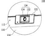
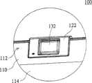
请同时参照图3A~3B,图3A是依照本实施例的显示器的影像撷取组件的俯视图,图3B是依照本实施例的显示器的影像撷取组件的俯视图,图3C是依照本实施例的显示器的影像撷取组件的俯视图。在影像撷取组件120中,第二壳体122具有一开口123,开口123贯穿第一表面与第二表面(未显示)。影像撷取单元130的二端是分别枢接于开口123的口壁。Please refer to FIGS. 3A-3B at the same time. FIG. 3A is a top view of the image capture component of the display according to this embodiment, FIG. 3B is a top view of the image capture component of the display according to this embodiment, and FIG. 3C is a top view of the image capture component of the display according to this embodiment. A top view of the image capture component of the display. In theimage capturing component 120 , thesecond casing 122 has anopening 123 , and theopening 123 passes through the first surface and the second surface (not shown). Two ends of theimage capturing unit 130 are respectively pivotally connected to the mouth wall of theopening 123 .

请参照图4,其是本实施例的显示器的影像撷取单元的立体分解图。第二壳体122具有一上盖122a与一下盖122b,共同具有开口123。上盖与122a下盖122b形成一容置空间。第二壳体122包括一底架124以及一固定座126。Please refer to FIG. 4 , which is an exploded perspective view of the image capturing unit of the display in this embodiment. Thesecond housing 122 has anupper cover 122 a and alower cover 122 b, which together have anopening 123 . Theupper cover 122a and thelower cover 122b form an accommodating space. Thesecond housing 122 includes abase frame 124 and a fixingseat 126 .

影像撷取单元130包括第三壳体132、镜头134、枢轴136、凸轮组件140。第三壳体132具有第一侧132a以及第二侧132b。镜头134设置于第三壳体132。枢轴136凸设于第三壳体132的一第一侧132a,并以可转动的方式卡接于底架124,借此,第三壳体132与镜头134是以枢轴136及其延伸线为一转动轴X相对第二壳体122转动。借由将影像撷取单元旋转至不同位置,以撷取不同角度的画面。Theimage capture unit 130 includes athird housing 132 , alens 134 , apivot 136 , and acam assembly 140 . Thethird housing 132 has afirst side 132a and asecond side 132b. Thelens 134 is disposed on thethird housing 132 . Thepivot 136 protrudes from afirst side 132a of thethird housing 132, and is rotatably engaged with thebottom frame 124, whereby thethird housing 132 and thelens 134 are connected by thepivot 136 and its extension. The line is a rotation axis X that rotates relative to thesecond casing 122 . Images from different angles are captured by rotating the image capture unit to different positions.

如图4所示,分段旋转组件140是以可转动的方式设置于第三壳体的第二侧132b,例如是分段旋转组件40以可沿着转动轴X转动的方式设置于中空轴体137中,且中空轴体137固设于第三壳体的第二侧132b。As shown in FIG. 4 , the segmentedrotating assembly 140 is rotatably disposed on thesecond side 132b of the third housing, for example, the segmented rotating assembly 40 is disposed on the hollow shaft in a manner rotatable along the rotation axis X. Thehollow shaft body 137 is fixed on thesecond side 132b of the third casing.

图5A是依照图4中影像撷取单元的分段旋转组件的立体图,图5B是依照图5A中影像撷取单元的分段旋转组件的立体分解图。请同时参照图5A~5B,在分段旋转组件140中,套筒141固接于第三壳体的第二侧132b,套筒141与枢轴136是分别位于第三壳体132的二侧,用以作为转动轴。卡接件142的一端142a卡接于固定座(图4中的126),卡接件的另一端142b套接于套筒141中。凸轮143固接于套筒141内,并相对卡接件142,凸轮143是与卡接件142互补,用以选择性地卡合于卡接件142。弹性体,例如是一弹簧144或一弹片,其套设于凸轮143,并位于套筒141内。FIG. 5A is a perspective view of the segmental rotation assembly of the image capture unit in FIG. 4 , and FIG. 5B is an exploded perspective view of the segmental rotation assembly of the image capture unit in FIG. 5A . Please refer to FIGS. 5A-5B at the same time. In thesegmented rotation assembly 140, thesleeve 141 is fixedly connected to thesecond side 132b of the third housing, and thesleeve 141 and thepivot 136 are respectively located on the two sides of thethird housing 132. , used as the axis of rotation. Oneend 142 a of the engagingmember 142 is engaged with the fixing seat ( 126 in FIG. 4 ), and theother end 142 b of the engaging member is sleeved in thesleeve 141 . Thecam 143 is fixed in thesleeve 141 and is opposite to the engagingmember 142 . Thecam 143 is complementary to the engagingmember 142 for selectively engaging with the engagingmember 142 . The elastic body, such as aspring 144 or an elastic piece, is sheathed on thecam 143 and located in thesleeve 141 .

请同时参照图5B及6A,图6A是本实施例的显示器的影像撷取单元于第一位置时的立体图。当第三壳体132转动,套筒141带动凸轮143沿转动轴X旋转至第一位置时,凸轮143嵌合于卡接件142,借此,镜头134是与第一表面共平面。请同时参照图5B及6B,图6B是本实施例的显示器的影像撷取单元由第一位置旋转至第二位置时的立体图。当第三壳体132带动凸轮143转动而离开第一位置时,卡接件142与凸轮143相抵,且凸轮143压缩弹簧144,此时,弹簧144提供一回复力,借此凸轮143朝向一第二位置旋转。请同时参照图5B及6C,图6C是本实施例的显示器的影像撷取单元于第二位置时的立体图。当第三壳体132带动凸轮143沿转动轴X旋转至第二位置时,凸轮143嵌合于卡接件142,借此,镜头134是与第二表面112共平面。如此一来,影像撷取单元可定位于最常使用的第一位置与第二位置,这种二段式定位的设计,使得影像撷取组件可固定于几组特定角度与位置上,以便利使用者使用与收纳影像撷取组件。Please refer to FIGS. 5B and 6A at the same time. FIG. 6A is a perspective view of the image capturing unit of the display in this embodiment when it is at the first position. When thethird casing 132 rotates, thesleeve 141 drives thecam 143 to rotate to the first position along the rotation axis X, and thecam 143 engages with the engagingmember 142 , whereby thelens 134 is coplanar with the first surface. Please refer to FIGS. 5B and 6B at the same time. FIG. 6B is a perspective view of the image capture unit of the display in this embodiment when it is rotated from the first position to the second position. When thethird housing 132 drives thecam 143 to rotate away from the first position, the engagingmember 142 is against thecam 143, and thecam 143 compresses thespring 144. At this time, thespring 144 provides a restoring force, whereby thecam 143 moves toward a first position. Two position rotation. Please refer to FIGS. 5B and 6C at the same time. FIG. 6C is a perspective view of the image capturing unit of the display in this embodiment when it is in the second position. When thethird housing 132 drives thecam 143 to rotate to the second position along the rotation axis X, thecam 143 is engaged with the engagingmember 142 , whereby thelens 134 is coplanar with thesecond surface 112 . In this way, the image capture unit can be positioned at the most frequently used first position and second position. This two-stage positioning design allows the image capture unit to be fixed at several specific angles and positions for convenience. The user uses and stores the image capture component.

本发明上述实施例所揭示的显示器及其影像撷取组件,其具有保护外壳的设计,可避免于开阖时对影像撷取单元产生不必要的移动与破坏。此外,其二段式定位的设计,使得影像撷取组件可固定于几组特定角度与位置上,以便利使用者使用与收纳影像撷取组件。The display and its image capture unit disclosed in the above-mentioned embodiments of the present invention have a protective shell design, which can avoid unnecessary movement and damage to the image capture unit when opening and closing. In addition, its two-stage positioning design enables the image capture component to be fixed at several specific angles and positions, which facilitates the user to use and store the image capture component.

综上所述,虽然本发明已以一较佳实施例揭示如上,然而其并非用以限定本发明,任何熟悉本技术的人员,在不脱离本发明的精神和范围内,当可作各种的等效的变化或替换,因此本发明的保护范围当视后附的本申请权利要求范围所界定的为准。In summary, although the present invention has been disclosed as above with a preferred embodiment, it is not intended to limit the present invention. Any person familiar with the art may make various Therefore, the scope of protection of the present invention should be defined by the appended claims of the application.

Claims (20)

Translated fromChinese
1.一种显示器,包括:1. A display comprising:一第一壳体,具有相对的一第一表面与一第二表面;A first shell having a first surface and a second surface opposite to each other;一显示面板,设置于该第一表面;以及a display panel disposed on the first surface; and一影像撷取组件;an image capture component;其特征在于,该影像撷取组件包括:It is characterized in that the image capture component includes:一第二壳体,固接于该第一壳体,该第二壳体具有一开口,该开口贯穿该第一表面与该第二表面;以及a second shell, fixed to the first shell, the second shell has an opening, the opening passes through the first surface and the second surface; and一影像撷取单元,其二端分别枢接于该开口的口壁,借此,该影像撷取单元是以可旋转的方式设置于该显示器。An image capture unit, the two ends of which are respectively pivotally connected to the mouth wall of the opening, whereby the image capture unit is rotatably arranged on the display.2.如权利要求1所述的显示器,其特征在于该第二壳体包括一底架,该影像撷取单元包括:2. The display according to claim 1, wherein the second housing comprises a chassis, and the image capturing unit comprises:一第三壳体;a third shell;一镜头,设置于该第三壳体;以及a lens set on the third casing; and一枢轴,凸设于该第三壳体的一第一侧,并以可转动的方式卡接于该底架,借此,该第三壳体与该镜头是以该枢轴及其延伸线为一转动轴相对该第二壳体转动。a pivot, protruding from a first side of the third casing, and rotatably fastened to the bottom frame, whereby the third casing and the lens are connected by the pivot and its extension The wire is a rotation axis that rotates relative to the second casing.3.如权利要求2所述的显示器,其特征在于该第二壳体还包括一固定座,该影像撷取单元还包括:3. The display according to claim 2, wherein the second casing further comprises a fixing base, and the image capture unit further comprises:一套筒,固接于该第三壳体的一第二侧,该套筒与该枢轴是分别位于该第三壳体的二侧,用以作为该转动轴;a sleeve fixedly connected to a second side of the third casing, the sleeve and the pivot are located on two sides of the third casing respectively, and are used as the rotation axis;一卡接件,其一端卡接于该固定座,另一端套接于该套筒中;A clamping piece, one end of which is clamped to the fixing seat, and the other end is sleeved in the sleeve;一凸轮,固接于该套筒内并相对该卡接件,该凸轮是与该卡接件互补,用以选择性地卡合于该卡接件;以及a cam, fixed in the sleeve and opposite to the clamping part, the cam is complementary to the clamping part, and is used to selectively engage with the clamping part; and一弹性体,套设于该凸轮并位于该套筒内;an elastic body is sleeved on the cam and located in the sleeve;其中,当该第三壳体转动,且该套筒带动该凸轮沿该转动轴旋转至一第一位置时,该凸轮嵌合于该卡接件,借此,该镜头与该第一表面共平面;Wherein, when the third casing rotates, and the sleeve drives the cam to rotate to a first position along the rotation axis, the cam is fitted into the snap-in member, whereby the lens and the first surface share flat;当该第三壳体转动,且该套筒带动该凸轮转动而离开该第一位置时,该卡接件与该凸轮相抵,且该凸轮压缩该弹性体,此时,该弹性体提供一回复力,借此该凸轮朝向一第二位置旋转;When the third housing rotates, and the sleeve drives the cam to rotate away from the first position, the snap-in part is against the cam, and the cam compresses the elastic body, at this time, the elastic body provides a return force, whereby the cam rotates toward a second position;当该第三壳体转动,且该套筒带动该凸轮沿该转动轴旋转至该第二位置时,该凸轮嵌合于该卡接件,借此,该镜头与该第二表面共平面。When the third casing rotates and the sleeve drives the cam to rotate to the second position along the rotation axis, the cam engages with the engaging member, whereby the lens is coplanar with the second surface.4.如权利要求3所述的显示器,其特征在于该弹性体是一弹簧或一弹片。4. The display as claimed in claim 3, wherein the elastic body is a spring or an elastic piece.5.如权利要求3所述的显示器,其特征在于该第二壳体包括一上盖与一下盖,并形成一容置空间,用以容置该固定座、该底架、该枢轴与该凸轮。5. The display as claimed in claim 3, wherein the second housing comprises an upper cover and a lower cover, and forms an accommodating space for accommodating the fixing base, the bottom frame, the pivot and the cam.6.如权利要求1所述的显示器,其特征在于该第二壳体凸出于该第一壳体的边缘,并高于该第一表面。6. The display as claimed in claim 1, wherein the second casing protrudes from an edge of the first casing and is higher than the first surface.7.如权利要求1所述的显示器,其特征在于该显示面板是一笔记本电脑的显示面板。7. The display as claimed in claim 1, wherein the display panel is a display panel of a notebook computer.8.一种显示器,包括:8. A display comprising:一第一壳体,具有相对的一第一表面与一第二表面;A first shell having a first surface and a second surface opposite to each other;一显示面板,设置于该第一表面;以及a display panel disposed on the first surface; and一影像撷取组件;an image capture component;其特征在于,It is characterized in that,该影像撷取组件贯穿该第一表面与该第二表面,包括:The image capture component runs through the first surface and the second surface, including:一第二壳体,固接于该第一壳体,该第二壳体具有一开口,该开口贯穿该第一表面与该第二表面;a second casing, fixedly connected to the first casing, the second casing has an opening, and the opening passes through the first surface and the second surface;一影像撷取单元,是以可旋转的方式设置于该显示器,并是选择性地定位于一第一位置与一第二位置;An image capture unit is rotatably arranged on the display, and is selectively positioned at a first position and a second position;其中,该影像撷取单元位于该开口中,且该影像撷取单元的二端分别枢接于该开口的口壁,借此,该影像撷取单元是以可旋转的方式设置于该第二壳体;当该影像撷取单元旋转至该第一位置时,该影像撷取单元的一前表面是与该第一表面共平面,当该影像撷取单元旋转至一第二位置时,该影像撷取单元的该前表面是与该第二表面共平面。Wherein, the image capture unit is located in the opening, and the two ends of the image capture unit are respectively pivotally connected to the mouth wall of the opening, whereby the image capture unit is rotatably arranged on the second Housing; when the image capture unit is rotated to the first position, a front surface of the image capture unit is coplanar with the first surface, and when the image capture unit is rotated to a second position, the The front surface of the image capture unit is coplanar with the second surface.9.如权利要求8所述的显示器,其特征在于该第二壳体包括一底架以及一固定座,该影像撷取单元包括:9. The display according to claim 8, wherein the second casing comprises a chassis and a fixing base, and the image capturing unit comprises:一第三壳体,具有相对的一第一侧与一第二侧;a third housing having a first side and a second side opposite to each other;一镜头,设置于该第三壳体,并位于该影像撷取组件的前表面;A lens is arranged on the third casing and is located on the front surface of the image capture component;一枢轴,凸设于该第三壳体的该第一侧,并以可转动的方式卡接于该底架,借此,该第三壳体与该镜头是以该枢轴为一转动轴相对该第二壳体转动;a pivot, protruding from the first side of the third casing, and rotatably engaged with the bottom frame, whereby the third casing and the lens rotate around the pivot the shaft rotates relative to the second housing;一套筒,固接于该第三壳体的该第二侧,该套筒与该枢轴是分别位于该第三壳体的二侧,用以作为该转动轴;a sleeve fixedly connected to the second side of the third casing, the sleeve and the pivot are located on two sides of the third casing respectively, and are used as the rotation axis;一卡接件,其一端卡接于该固定座,另一端套接于该套筒中;A clamping piece, one end of which is clamped to the fixing seat, and the other end is sleeved in the sleeve;一凸轮,固接于该套筒内并相对该卡接件,该凸轮是与该卡接件互补,用以选择性地卡合于该卡接件;以及a cam, fixed in the sleeve and opposite to the clamping part, the cam is complementary to the clamping part, and is used to selectively engage with the clamping part; and一弹性体,套设于该凸轮并位于该套筒内;an elastic body is sleeved on the cam and located in the sleeve;其中,当该第三壳体转动,且该套筒带动该凸轮沿该转动轴旋转至一第一位置时,该凸轮嵌合于该卡接件,借此,该镜头与该第一表面共平面;Wherein, when the third casing rotates, and the sleeve drives the cam to rotate to a first position along the rotation axis, the cam is fitted into the snap-in member, whereby the lens and the first surface share flat;当该第三壳体转动,且该套筒带动该凸轮转动而离开该第一位置时,该卡接件与该凸轮相抵,且该凸轮压缩该弹性体,此时,该弹性体提供一回复力,借此该凸轮朝向一第二位置旋转;When the third housing rotates, and the sleeve drives the cam to rotate away from the first position, the snap-in part is against the cam, and the cam compresses the elastic body, at this time, the elastic body provides a return force, whereby the cam rotates toward a second position;当该第三壳体转动,且该套筒带动该凸轮沿该转动轴旋转至该第二位置时,该凸轮嵌合于该卡接件,借此,该镜头与该第二表面共平面。When the third casing rotates and the sleeve drives the cam to rotate to the second position along the rotation axis, the cam engages with the engaging member, whereby the lens is coplanar with the second surface.10.如权利要求9所述的显示器,其特征在于该弹性体是一弹簧或一弹片。10. The display as claimed in claim 9, wherein the elastic body is a spring or an elastic piece.11.如权利要求9所述的显示器,其特征在于该第二壳体包括一上盖与一下盖并形成一容置空间,用以容置该固定座、该底架、该枢轴与该凸轮。11. The display as claimed in claim 9, wherein the second casing comprises an upper cover and a lower cover to form an accommodating space for accommodating the fixing seat, the bottom frame, the pivot and the cam.12.如权利要求8所述的显示器,其特征在于该第二壳体凸出于该第一壳体的边缘,并高于该第一表面。12. The display as claimed in claim 8, wherein the second casing protrudes from an edge of the first casing and is higher than the first surface.13.如权利要求8所述的显示器,其特征在于该显示面板是一笔记本电脑的显示面板。13. The display as claimed in claim 8, wherein the display panel is a display panel of a notebook computer.14.一种影像撷取组件,用以设置于一显示器中,该显示器包括一显示面板以及一第一壳体,该第一壳体具有相对的一第一表面以及一第二表面,该显示面板设置于该第一表面,其特征在于,该影像撷取组件包括:14. An image capture component for being arranged in a display, the display comprising a display panel and a first casing, the first casing has a first surface and a second surface opposite to each other, the display The panel is arranged on the first surface, and the feature is that the image capture component includes:一第二壳体,固接于该第一壳体,具有一开口,该开口贯穿一第一表面与一第二表面;以及A second shell, fixed to the first shell, has an opening, and the opening passes through a first surface and a second surface; and一影像撷取单元,包括:An image capture unit, including:一第三壳体;a third shell;一镜头,设置于该第三壳体;及a lens set on the third casing; and一枢轴,凸设于该第三壳体的一第一侧,并以可转动的方式卡接于该第二壳体,借此,该第三壳体与该镜头是以该枢轴为一转动轴相对该第二壳体转动。a pivot, protruding from a first side of the third casing, and rotatably fastened to the second casing, whereby the third casing and the lens take the pivot as a A rotating shaft rotates relative to the second casing.15.如权利要求14所述的影像撷取组件,其特征在于该第二壳体还包括一底架,其相对于该第三壳体的该第一侧并套接于该枢轴。15 . The image capture component as claimed in claim 14 , wherein the second housing further comprises a bottom frame, which is opposite to the first side of the third housing and sleeved on the pivot. 15 .16.如权利要求14所述的影像撷取组件,其特征在于该第二壳体还包括一固定座,该影像撷取单元还包括:16. The image capture unit according to claim 14, wherein the second casing further comprises a fixing seat, and the image capture unit further comprises:一套筒,固接于该第三壳体的一第二侧,该套筒与该枢轴是分别位于该第三壳体的二侧,用以作为该转动轴;a sleeve fixedly connected to a second side of the third casing, the sleeve and the pivot are located on two sides of the third casing respectively, and are used as the rotation axis;一卡接件,其一端卡接于该固定座,另一端套接于该套筒中;A clamping piece, one end of which is clamped to the fixing seat, and the other end is sleeved in the sleeve;一凸轮,固接于该套筒内,并相对该卡接件,该凸轮是与该卡接件互补,用以选择性地卡合于该卡接件;以及a cam, fixed in the sleeve, opposite to the clamping part, the cam is complementary to the clamping part, and is used to selectively engage with the clamping part; and一弹性体,其套设于该凸轮并位于该套筒内;an elastic body is sleeved on the cam and located in the sleeve;其中,当该第三壳体转动,且该套筒带动该凸轮沿该转动轴旋转至一第一位置时,该凸轮嵌合于该卡接件,借此,该镜头是与该第一表面共平面;Wherein, when the third casing rotates, and the sleeve drives the cam to rotate to a first position along the rotation axis, the cam is fitted into the snap-in member, whereby the lens is in contact with the first surface Coplanar;当该第三壳体转动,且该套筒带动该凸轮转动而离开该第一位置时,该卡接件与该凸轮相抵,且该凸轮压缩该弹性体,此时,该弹性体提供一回复力,借此该凸轮朝向一第二位置旋转;When the third housing rotates, and the sleeve drives the cam to rotate away from the first position, the snap-in part is against the cam, and the cam compresses the elastic body, at this time, the elastic body provides a return force, whereby the cam rotates toward a second position;当该第三壳体转动,且该套筒带动该凸轮沿该转动轴旋转至该第二位置时,该凸轮嵌合于该卡接件,借此,该镜头与该第二表面共平面。When the third casing rotates and the sleeve drives the cam to rotate to the second position along the rotation axis, the cam engages with the engaging member, whereby the lens is coplanar with the second surface.17.如权利要求16所述的影像撷取组件,其特征在于该弹性体是一弹簧或一弹片。17. The image capture component as claimed in claim 16, wherein the elastic body is a spring or a shrapnel.18.如权利要求16所述的影像撷取组件,其特征在于该第二壳体包括一底架、一上盖与一下盖,该底架相对于该第三壳体的该第一侧并套接于该枢轴,该上盖与该下盖形成一容置空间,用以容置该固定座、该底架、该枢轴与该凸轮。18. The image capture unit as claimed in claim 16, wherein the second casing comprises a bottom frame, an upper cover and a lower cover, and the bottom frame is parallel to the first side of the third casing. Sleeved on the pivot, the upper cover and the lower cover form an accommodating space for accommodating the fixing seat, the bottom frame, the pivot and the cam.19.如权利要求14所述的影像撷取组件,其特征在于该第二壳体凸出于该第一壳体的边缘,并高于该第一表面。19. The image capture component as claimed in claim 14, wherein the second housing protrudes from the edge of the first housing and is higher than the first surface.20.如权利要求14所述的影像撷取组件,其特征在于该显示面板是一笔记本电脑的显示面板。20. The image capture component as claimed in claim 14, wherein the display panel is a display panel of a notebook computer.
CNB2005100047475A2005-01-212005-01-21Display with rotatable image acquisition assemblyExpired - LifetimeCN100454211C (en)

Priority Applications (1)

Application NumberPriority DateFiling DateTitle
CNB2005100047475ACN100454211C (en)2005-01-212005-01-21Display with rotatable image acquisition assembly

Applications Claiming Priority (1)

Application NumberPriority DateFiling DateTitle
CNB2005100047475ACN100454211C (en)2005-01-212005-01-21Display with rotatable image acquisition assembly

Publications (2)

Publication NumberPublication Date
CN1808329A CN1808329A (en)2006-07-26
CN100454211Ctrue CN100454211C (en)2009-01-21

Family

ID=36840258

Family Applications (1)

Application NumberTitlePriority DateFiling Date
CNB2005100047475AExpired - LifetimeCN100454211C (en)2005-01-212005-01-21Display with rotatable image acquisition assembly

Country Status (1)

CountryLink
CN (1)CN100454211C (en)

Citations (4)

* Cited by examiner, † Cited by third party
Publication numberPriority datePublication dateAssigneeTitle
WO1999003278A1 (en)*1997-07-091999-01-21Briot InternationalVideo system for sales assistance to opticians
JP2000020163A (en)*1998-06-302000-01-21Sony CorpInformation processor
CN1349145A (en)*2000-10-132002-05-15Lg电子株式会社 Device for automatically adjusting the angle of an image device of an information processing device
EP1494437A1 (en)*2003-07-042005-01-05LG Electronics Inc.Rotary camera for mobile communication device

Patent Citations (4)

* Cited by examiner, † Cited by third party
Publication numberPriority datePublication dateAssigneeTitle
WO1999003278A1 (en)*1997-07-091999-01-21Briot InternationalVideo system for sales assistance to opticians
JP2000020163A (en)*1998-06-302000-01-21Sony CorpInformation processor
CN1349145A (en)*2000-10-132002-05-15Lg电子株式会社 Device for automatically adjusting the angle of an image device of an information processing device
EP1494437A1 (en)*2003-07-042005-01-05LG Electronics Inc.Rotary camera for mobile communication device

Also Published As

Publication numberPublication date
CN1808329A (en)2006-07-26

Similar Documents

PublicationPublication DateTitle
JP5517090B2 (en) Portable electronic devices
US10203729B1 (en)Portable electronic device
US8134638B2 (en)Display with rotatable image capturing module
US10678309B2 (en)Camera module and electronic device
US8339777B2 (en)Portable electronic device with improved pivoting range
CN110058644B (en)Electronic device
CN209327901U (en)Bending structure and flexible screen display equipment
CN103262508A (en) portable electronic device
US20080074835A1 (en)Image-capturing module and portable computer having the same
TWM601367U (en)Portable electronic device
TWI767836B (en)Electronic device
CN100454211C (en)Display with rotatable image acquisition assembly
US20140111925A1 (en)Electronic device
JP5554682B2 (en) Portable electronic devices
TWI619005B (en)Electronic device
CN201340572Y (en)Image acquisition module
CN1988557A (en)Hinge device and mobile apparatus having the same
CN100524160C (en)Image acquisition module and portable computer with same
CN2814908Y (en) Sliding mechanism for electronic devices
CN2681174Y (en)Portable electronic device with built-in digital camera
CN1848694A (en) Electronic device with automatic flip display module
CN210129134U (en)Electronic device with camera module
CN100435065C (en)Rotary positioning module of display and notebook computer
TWI298121B (en)
CN101192078B (en)Portable computer device

Legal Events

DateCodeTitleDescription
C06Publication
PB01Publication
C10Entry into substantive examination
SE01Entry into force of request for substantive examination
C14Grant of patent or utility model
GR01Patent grant
CX01Expiry of patent term

Granted publication date:20090121

CX01Expiry of patent term

[8]ページ先頭

©2009-2025 Movatter.jp