CN100454098C - Light-guiding plate - Google Patents
Light-guiding plateDownload PDFInfo
- Publication number
- CN100454098C CN100454098CCNB2005100334732ACN200510033473ACN100454098CCN 100454098 CCN100454098 CCN 100454098CCN B2005100334732 ACNB2005100334732 ACN B2005100334732ACN 200510033473 ACN200510033473 ACN 200510033473ACN 100454098 CCN100454098 CCN 100454098C
- Authority
- CN
- China
- Prior art keywords
- guide plate
- light guide
- light
- holes
- exiting
- Prior art date
- Legal status (The legal status is an assumption and is not a legal conclusion. Google has not performed a legal analysis and makes no representation as to the accuracy of the status listed.)
- Expired - Fee Related
Links
Images


Landscapes
- Light Guides In General And Applications Therefor (AREA)
- Planar Illumination Modules (AREA)
Abstract
Description
Translated fromChinese【技术领域】【Technical field】
本发明是关于一种导光板。The invention relates to a light guide plate.
【背景技术】【Background technique】
由于液晶显示器面板中的液晶本身不具备发光特性,因而,为达到显示效果,须给液晶显示器面板提供一面光源装置,如背光模组,其功能在于向液晶显示器面板供应亮度充分且分布均匀的面光源。Since the liquid crystal in the LCD panel itself does not have light-emitting characteristics, in order to achieve the display effect, it is necessary to provide the LCD panel with a light source device, such as a backlight module, whose function is to supply the LCD panel with a surface with sufficient brightness and uniform distribution. light source.
现有技术背光模组由光源、反射板、导光板、扩散板及棱镜层等构成,其中导光板是背光模组中的关键组件,其作用在于引导入射光经导光板散射及反射而转换成面光源。The prior art backlight module is composed of a light source, a reflector, a light guide plate, a diffusion plate, and a prism layer. The light guide plate is a key component in the backlight module, and its function is to guide the incident light to be scattered and reflected by the light guide plate and converted into surface light source.
请参看图1,是一种现有的背光模组的示意图。该背光模组200包括一光源210,一导光板220,一反射板230及一扩散板240。该导光板220包括一入光面222,一与该入光面相邻的出光面223,及一与该出光面223相对的底面224。该光源210邻近该入光面222设置,该反射板230邻近该底面224设置,该扩散板240邻近该出光面223设置。该底面224上设置有均匀分布的多个圆形扩散点226。该扩散点226可有效反射及扩散射至其上的光线,从而提高该导光板220和该背光模组200的光利用率与出光均匀度。Please refer to FIG. 1 , which is a schematic diagram of a conventional backlight module. The
但是,该光源210发出的光线自入光面222进入导光板220后,部分光线需在导光板220中间穿过,光程较长,且需经过多次反射,会造成光损失,从而导致该导光板220的光利用率降低。However, after the light emitted by the
【发明内容】【Content of invention】
为解决现有技术导光板光利用率较低的问题,提供一种具有较高光利用率的导光板实为必要。In order to solve the problem of the low light utilization rate of the light guide plate in the prior art, it is necessary to provide a light guide plate with a higher light utilization rate.
解决该技术问题的一种技术方案是:提供一种导光板,其包括一入光面,一与该入光面相邻的出光面,及一与该出光面相对的底面。该导光板内部具有多个通孔,每一通孔至少有一端贯穿底面或出光面,该多个通孔呈开口背向入光面的折线形,该多个通孔的形状是金字塔形或圆台形。A technical solution to solve this technical problem is to provide a light guide plate, which includes a light incident surface, a light exit surface adjacent to the light incident surface, and a bottom surface opposite to the light exit surface. There are a plurality of through holes inside the light guide plate, each through hole has at least one end running through the bottom surface or the light-emitting surface, and the plurality of through-holes are in the shape of a broken line with the opening facing away from the light-incident surface, and the shape of the plurality of through-holes is pyramidal or circular. Table shape.
解决该技术问题的另一种技术方案是:提供一种导光板,其包括一入光面,一与该入光面相邻的出光面,及一与该出光面相对的底面。该导光板内部具有多个通孔,每一通孔至少有一端贯穿底面或出光面,该多个通孔呈开口背向入光面的折线形,该导光板的材质为聚甲基丙烯酸甲酯或聚碳酸酯。Another technical solution to solve this technical problem is to provide a light guide plate, which includes a light incident surface, a light exit surface adjacent to the light incident surface, and a bottom surface opposite to the light exit surface. The light guide plate has a plurality of through holes inside, and at least one end of each through hole runs through the bottom surface or the light-emitting surface. The plurality of through holes are in the shape of a broken line with the opening facing away from the light-incident surface. The material of the light guide plate is polymethyl methacrylate. or polycarbonate.
解决该技术问题的第三种技术方案是:提供一种导光板,其包括一入光面,一与该入光面相邻的出光面,及一与该出光面相对的底面。该导光板内部具有多个通孔,每一通孔至少有一端贯穿底面或出光面,该多个通孔呈开口背向入光面的折线形,该多个通孔是等径的圆形通孔,且基本平行等距设置。The third technical solution to solve this technical problem is to provide a light guide plate, which includes a light incident surface, a light exit surface adjacent to the light incident surface, and a bottom surface opposite to the light exit surface. There are a plurality of through holes inside the light guide plate, and at least one end of each through hole runs through the bottom surface or the light-emitting surface. holes, and are basically parallel and equidistant.
解决该技术问题的第四种技术方案是:提供一种导光板,其包括一入光面,一与该入光面相邻的出光面,及一与该出光面相对的底面。该导光板内部具有多个通孔,每一通孔至少有一端贯穿底面或出光面,该多个通孔呈开口背向入光面的折线形,该出光面为雾化表面。The fourth technical solution to solve this technical problem is to provide a light guide plate, which includes a light incident surface, a light exit surface adjacent to the light incident surface, and a bottom surface opposite to the light exit surface. The light guide plate has a plurality of through holes inside, and at least one end of each through hole runs through the bottom surface or the light-emitting surface.
解决该技术问题的第五种技术方案是:提供一种导光板,其包括一入光面,一与该入光面相邻的出光面,及一与该出光面相对的底面。该导光板内部具有多个通孔,每一通孔至少有一端贯穿底面或出光面,该多个通孔呈开口背向入光面的折线形,该底面上设置有多个扩散点。The fifth technical solution to solve this technical problem is to provide a light guide plate, which includes a light incident surface, a light exit surface adjacent to the light incident surface, and a bottom surface opposite to the light exit surface. The light guide plate has a plurality of through holes inside, and at least one end of each through hole runs through the bottom surface or the light-emitting surface.
解决该技术问题的第六种技术方案是:提供一种导光板,其包括一入光面,一与该入光面相邻的出光面,及一与该出光面相对的底面,其特征在于:该导光板内部具有多个通孔,每一通孔至少有一端贯穿底面或出光面,该导光板的多个通孔互相交叉,交叉的通孔位于垂直于入光面的平面上。The sixth technical solution to solve this technical problem is to provide a light guide plate, which includes a light incident surface, a light exit surface adjacent to the light incident surface, and a bottom surface opposite to the light exit surface, characterized in that The light guide plate has a plurality of through holes inside, and at least one end of each through hole penetrates the bottom surface or the light-emitting surface, and the plurality of through-holes of the light guide plate intersect with each other, and the intersecting through-holes are located on a plane perpendicular to the light-incident surface.
解决该技术问题的第七种技术方案是:一种导光板,其包括一入光面,一与该入光面相邻的出光面,及一与该出光面相对的底面,其特征在于:该导光板内部具有多个通孔,每一通孔至少有一端贯穿底面或出光面,该导光板的多个通孔位于不同的垂直于入光面的平面上,其正投影互相交叉。The seventh technical solution to solve this technical problem is: a light guide plate, which includes a light incident surface, a light exit surface adjacent to the light incident surface, and a bottom surface opposite to the light exit surface, characterized in that: There are a plurality of through holes inside the light guide plate, and at least one end of each through hole penetrates the bottom surface or the light exit surface. The plurality of through holes of the light guide plate are located on different planes perpendicular to the light incident surface, and their orthographic projections intersect each other.
该技术方案的导光板包含有多个通孔,该多个通孔在该导光板内部形成多个曲面,可以为入射光线提供多个反射及折射面。光源发出的光线进入导光板后,光线可被该多个曲面反射及折射向出光面,可避免光程太长及多次反射造成的光损失,从而可提高导光板的光利用率。导光板内部设置多个通孔,还可以减轻导光板的重量,更加符合导光组件越来越轻量化的发展趋势。The light guide plate of this technical solution includes a plurality of through holes, and the plurality of through holes form a plurality of curved surfaces inside the light guide plate, which can provide multiple reflection and refraction surfaces for incident light. After the light emitted by the light source enters the light guide plate, the light can be reflected by the plurality of curved surfaces and refracted toward the light emitting surface, which can avoid light loss caused by too long optical path and multiple reflections, thereby improving the light utilization rate of the light guide plate. A plurality of through holes are provided inside the light guide plate, which can also reduce the weight of the light guide plate, which is more in line with the development trend of light guide components becoming lighter and lighter.
【附图说明】【Description of drawings】
图1是一种现有的导光板的侧视图。Fig. 1 is a side view of a conventional light guide plate.
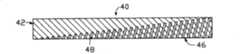
图2是本发明导光板第一实施方式的剖视图。Fig. 2 is a cross-sectional view of the first embodiment of the light guide plate of the present invention.
图3是本发明导光板第一实施方式的俯视图。Fig. 3 is a top view of the first embodiment of the light guide plate of the present invention.
图4是本发明导光板第二实施方式的剖视图。Fig. 4 is a cross-sectional view of the second embodiment of the light guide plate of the present invention.
图5是本发明导光板第三实施方式的剖视图。Fig. 5 is a cross-sectional view of a third embodiment of the light guide plate of the present invention.
图6是本发明导光板第四实施方式的剖视图。Fig. 6 is a cross-sectional view of a fourth embodiment of a light guide plate of the present invention.
图7是本发明导光板第五实施方式的剖视图。Fig. 7 is a cross-sectional view of a fifth embodiment of the light guide plate of the present invention.
图8是本发明导光板第六实施方式的剖视图。Fig. 8 is a cross-sectional view of the sixth embodiment of the light guide plate of the present invention.
图9是本发明导光板第七实施方式的剖视图。9 is a cross-sectional view of a seventh embodiment of a light guide plate of the present invention.
图10是本发明导光板第八实施方式的剖视图。Fig. 10 is a cross-sectional view of the eighth embodiment of the light guide plate of the present invention.
图11是本发明导光板第九实施方式的剖视图。Fig. 11 is a cross-sectional view of the ninth embodiment of the light guide plate of the present invention.
【具体实施方式】【Detailed ways】
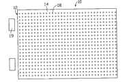
请参看图2和图3,分别是本发明导光板第一实施方式的剖视图和俯视图。该导光板10包括一入光面12,一与该入光面12相邻的出光面14,及一与该出光面相对的底面16。该导光板10的材质是透明材料,如聚甲基丙烯酸甲酯(Polymthyl Metharylate,PMMA)或聚碳酸酯(Polycarbonate,PC)。该导光板10组装入背光模组时,其入光面12侧会设置至少一光源19。Please refer to FIG. 2 and FIG. 3 , which are respectively a cross-sectional view and a top view of the first embodiment of the light guide plate of the present invention. The
该导光板10还包括多个圆形通孔18。该多个通孔18基本平行设置于该导光板10内部,与该底面16成一固定角度α,该角度α的大小为0<α<180°。该多个通孔18等距设置,其直径均相同。The
该多个通孔18在导光板10内部形成多个曲面,可为入射光线提供多个反射及折射面。光源19发出的光线进入导光板10后,光线可被该多个曲面反射及折射向出光面,可避免光程太长及多次反射造成的光损失,从而可提高导光板10的光利用率。导光板10内部设置多个通孔18,还可以减轻导光板10的重量,更加符合导光组件越来越轻量化的发展趋势。The plurality of through
请参看图4,是本发明导光板第二实施方式的剖视图。该导光板20与第一实施方式的导光板10的区别在于:该导光板20的多个通孔28的直径并不统一,可根据出光要求设置为沿远离入光面22方向渐宽、渐窄或宽窄交替分布。Please refer to FIG. 4 , which is a cross-sectional view of the second embodiment of the light guide plate of the present invention. The difference between the
请参看图5,是本发明导光板第三实施方式的剖视图。该导光板30与第一实施方式的导光板10的区别在于:该导光板30的多个通孔38非等距设置,可根据出光要求设置为沿远离入光面32方向渐密、渐疏或疏密交替分布。Please refer to FIG. 5 , which is a cross-sectional view of a third embodiment of the light guide plate of the present invention. The difference between the
请参看图6,是本发明导光板第四实施方式的剖视图。该导光板40与第一实施方式的导光板10的区别在于:该导光板40的多个通孔48一端与该导光板40的底面46贯通,另一端则分布于该导光板40的对角面上,且该多个通孔48沿远离入光面42方向高度渐升、渐降或高低交替分布。Please refer to FIG. 6 , which is a cross-sectional view of a fourth embodiment of the light guide plate of the present invention. The difference between the
请参看图7,是本发明导光板第五实施方式的剖视图。该导光板50与第一实施方式的导光板10的区别在于:该导光板50的多个通孔58一端与该导光板50的出光面54贯通,另一端则分布于该导光板50的对角面上,且该多个通孔58沿远离入光面52方向高度渐升、渐降或高低交替分布。Please refer to FIG. 7 , which is a cross-sectional view of a fifth embodiment of the light guide plate of the present invention. The difference between the light guide plate 50 and the
请参看图8,是本发明导光板第六实施方式的剖视图。该导光板60与第一实施方式的导光板10的区别在于:该导光板60的多个通孔68非平行设置,其与底面66的夹角为β,该夹角β的大小为0<β<180°,且沿远离入光面62方向渐增或渐减。Please refer to FIG. 8 , which is a cross-sectional view of the sixth embodiment of the light guide plate of the present invention. The difference between the
请参看图9,是本发明导光板第七实施方式的剖视图。该导光板70与第一实施方式的导光板10的区别在于:该导光板70的多个通孔78互相交叉,交叉的通孔78位于垂直于入光面(未标示)的平面上。当然,交叉的通孔78分别位于不同的垂直于入光面的平面上,其正投影互相交叉,也可以实现同样的功效。Please refer to FIG. 9 , which is a cross-sectional view of a seventh embodiment of the light guide plate of the present invention. The difference between the
请参看图10,是本发明导光板第八实施方式的剖视图。该导光板80与第一实施方式的导光板10的区别在于:该导光板80的多个通孔88呈开口背向入光面82的折线形。本实施方式的导光板80还具有意外的功效,即可用于双面发光背光模组,可大大增强双面发光效果。Please refer to FIG. 10 , which is a cross-sectional view of the eighth embodiment of the light guide plate of the present invention. The difference between the light guide plate 80 and the
请参看图11,是本发明导光板第九实施方式的剖视图。该导光板90与第一实施方式的导光板10的区别在于:该导光板90的多个通孔98的形状为圆锥形。Please refer to FIG. 11 , which is a cross-sectional view of the ninth embodiment of the light guide plate of the present invention. The difference between the
本发明的导光板还具有其它多种实施方式,例如:多个通孔也可以结合直径、间距及高度作多种组合变化;多个通孔也可以高度相同,且其仅一端贯穿导光板的底面或出光面;多个通孔的形状也可以是金字塔形或圆台形;导光板的出光面及底面可设置扩散点或作雾化处理。The light guide plate of the present invention also has other various implementation modes, for example: multiple through holes can also be changed in various combinations in combination with diameter, spacing and height; multiple through holes can also be of the same height, and only one end of them penetrates through the light guide plate The bottom surface or the light-emitting surface; the shape of the multiple through holes can also be pyramidal or truncated; the light-emitting surface and the bottom surface of the light guide plate can be provided with diffusion points or atomized.
Claims (10)
Priority Applications (1)
| Application Number | Priority Date | Filing Date | Title |
|---|---|---|---|
| CNB2005100334732ACN100454098C (en) | 2005-03-05 | 2005-03-05 | Light-guiding plate |
Applications Claiming Priority (1)
| Application Number | Priority Date | Filing Date | Title |
|---|---|---|---|
| CNB2005100334732ACN100454098C (en) | 2005-03-05 | 2005-03-05 | Light-guiding plate |
Publications (2)
| Publication Number | Publication Date |
|---|---|
| CN1828385A CN1828385A (en) | 2006-09-06 |
| CN100454098Ctrue CN100454098C (en) | 2009-01-21 |
Family
ID=36946852
Family Applications (1)
| Application Number | Title | Priority Date | Filing Date |
|---|---|---|---|
| CNB2005100334732AExpired - Fee RelatedCN100454098C (en) | 2005-03-05 | 2005-03-05 | Light-guiding plate |
Country Status (1)
| Country | Link |
|---|---|
| CN (1) | CN100454098C (en) |
Families Citing this family (2)
| Publication number | Priority date | Publication date | Assignee | Title |
|---|---|---|---|---|
| WO2017098718A1 (en)* | 2015-12-07 | 2017-06-15 | 富士フイルム株式会社 | Backlight unit |
| WO2019136572A1 (en)* | 2018-01-15 | 2019-07-18 | 璩泽明 | Light guide plate having array of light guide holes with high aspect ratio and manufacturing method therefor |
Citations (5)
| Publication number | Priority date | Publication date | Assignee | Title |
|---|---|---|---|---|
| WO2002101448A1 (en)* | 2001-06-08 | 2002-12-19 | Fawoo Technology Co., Ltd. | Light guide plate used for backlight unit |
| US6565225B2 (en)* | 2000-07-19 | 2003-05-20 | Sanyo Electric Co., Ltd. | Bar-shaped light guide, beam lighting device using the bar-shaped light guide, and surface lighting device using the beam lighting device |
| JP2003257229A (en)* | 2002-02-27 | 2003-09-12 | Alps Electric Co Ltd | Backlight, front light, and liquid crystal display device |
| CN1510487A (en)* | 2002-12-20 | 2004-07-07 | 西铁城电子股份有限公司 | Light conducting board and supporter for it |
| CN2763846Y (en)* | 2004-12-30 | 2006-03-08 | 群康科技(深圳)有限公司 | Light guiding board |
- 2005
- 2005-03-05CNCNB2005100334732Apatent/CN100454098C/ennot_activeExpired - Fee Related
Patent Citations (5)
| Publication number | Priority date | Publication date | Assignee | Title |
|---|---|---|---|---|
| US6565225B2 (en)* | 2000-07-19 | 2003-05-20 | Sanyo Electric Co., Ltd. | Bar-shaped light guide, beam lighting device using the bar-shaped light guide, and surface lighting device using the beam lighting device |
| WO2002101448A1 (en)* | 2001-06-08 | 2002-12-19 | Fawoo Technology Co., Ltd. | Light guide plate used for backlight unit |
| JP2003257229A (en)* | 2002-02-27 | 2003-09-12 | Alps Electric Co Ltd | Backlight, front light, and liquid crystal display device |
| CN1510487A (en)* | 2002-12-20 | 2004-07-07 | 西铁城电子股份有限公司 | Light conducting board and supporter for it |
| CN2763846Y (en)* | 2004-12-30 | 2006-03-08 | 群康科技(深圳)有限公司 | Light guiding board |
Also Published As
| Publication number | Publication date |
|---|---|
| CN1828385A (en) | 2006-09-06 |
Similar Documents
| Publication | Publication Date | Title |
|---|---|---|
| CN201437963U (en) | Improved structure of light guide plate | |
| CN101644415B (en) | Light guide plate and backlight module | |
| CN101126822B (en) | Optical board and backlight module using the optical board | |
| US8287172B2 (en) | Planar illumination device | |
| CN101000387A (en) | Prism and backlight module using the prism | |
| US20100027240A1 (en) | Lighting device | |
| CN101676620A (en) | Liquid crystal display device, backlight module and light-emitting unit | |
| CN2588388Y (en) | Light conducting board device | |
| CN207586464U (en) | Backlight module and display device | |
| CN201137875Y (en) | Light guide column | |
| CN102840520B (en) | Sidelight type backlight module and display device | |
| TW200846731A (en) | Lightguide plate and backlight module | |
| CN101042493A (en) | Back light module unit and light conducting plate thereof | |
| CN201606821U (en) | A light guide plate and a backlight module | |
| WO2013002015A1 (en) | Illuminating device and display device | |
| CN201078650Y (en) | light guide plate | |
| TW201430459A (en) | Back-lit module and light guide plate of the same | |
| CN100454098C (en) | Light-guiding plate | |
| JP2012048914A (en) | Lighting device and liquid crystal display using the same | |
| CN204666858U (en) | A light guide plate with improved luminance | |
| CN107340648A (en) | Back board structure, backlight module, the preparation method of display device and back board structure | |
| CN201083930Y (en) | Improved structure of backlight module | |
| KR20010046581A (en) | Backlight device for display | |
| CN2938145Y (en) | Structural improvement of light guide plate and liquid crystal display device having the light guide plate | |
| CN100405155C (en) | Backlight module |
Legal Events
| Date | Code | Title | Description |
|---|---|---|---|
| C06 | Publication | ||
| PB01 | Publication | ||
| C10 | Entry into substantive examination | ||
| SE01 | Entry into force of request for substantive examination | ||
| C14 | Grant of patent or utility model | ||
| GR01 | Patent grant | ||
| CF01 | Termination of patent right due to non-payment of annual fee | ||
| CF01 | Termination of patent right due to non-payment of annual fee | Granted publication date:20090121 Termination date:20170305 |