CN100450703C - molding method - Google Patents
molding methodDownload PDFInfo
- Publication number
- CN100450703C CN100450703CCNB2004100685541ACN200410068554ACN100450703CCN 100450703 CCN100450703 CCN 100450703CCN B2004100685541 ACNB2004100685541 ACN B2004100685541ACN 200410068554 ACN200410068554 ACN 200410068554ACN 100450703 CCN100450703 CCN 100450703C
- Authority
- CN
- China
- Prior art keywords
- mold core
- mold
- nickel
- molding method
- workpiece
- Prior art date
- Legal status (The legal status is an assumption and is not a legal conclusion. Google has not performed a legal analysis and makes no representation as to the accuracy of the status listed.)
- Expired - Fee Related
Links
Images

Landscapes
- Mounting, Exchange, And Manufacturing Of Dies (AREA)
Abstract
Description
Translated fromChinese技术领域technical field
本发明有关一种模制成型方法,特别是一种可以制作出高加工精密度工件的一种模制成型方法。The invention relates to a molding method, in particular to a molding method capable of producing workpieces with high processing precision.
背景技术Background technique
现行的模制成型方法,广泛地被应用来制作一些工件,使其应用至所需要的地方,其原理不外乎是先制作出一模仁,此模仁的形状恰与所欲成型完成的工件的形状完全相反,再以此模仁对工件进行冲压,脱模后可以得致所欲成型的形状的工件。The current molding method is widely used to make some workpieces and apply them to the required places. The principle is nothing more than to make a mold core first. The shape of the mold core is exactly the shape of the desired molding. The shape of the workpiece is completely opposite, and then the workpiece is stamped with this mold core, and the workpiece with the desired shape can be obtained after demoulding.
一种现有技术的模制成型方法如图1所示,首先,为了制作出一模仁,先准备一未加工的模仁材料10,接下来利用一般的机械加工方法,将未加工的模仁材料10加工而形成一模仁11,其机械加工方法包含传统技术的钻、铣、车、磨等方法,目的在制作出一与欲成型完成的工件的形状完全相反的模仁11,以便后续冲压使用;接下来,将模仁11紧密接合于一模座12上,以形成一模具1;接下来,利用此模具1针对一工件2进行冲压,经过模具1的退模过程后,即可以形成一所欲成型的工件2。A prior art molding method is shown in Figure 1. First, in order to make a mold core, an unprocessed mold core material 10 is first prepared, and then the unprocessed mold core material 10 is prepared using a general mechanical processing method. The mold core material 10 is processed to form a mold core 11, and its mechanical processing methods include traditional techniques such as drilling, milling, turning, grinding, etc. The purpose is to produce a mold core 11 that is completely opposite to the shape of the workpiece to be formed. For subsequent stamping use; Next, the mold core 11 is tightly bonded to a mold base 12 to form a mold 1; Next, use this mold 1 to stamp a workpiece 2, and after the ejection process of the mold 1, That is, a workpiece 2 to be formed can be formed.
上述现有技术的模制成型方法,有快速制作、易大量生产的优点,但是,现今有一些机构或是装置,所需要的组件的尺寸很小,现有技术的模制成型方法中的模仁制作过程,由于是利用现有技术的钻、铣、车、磨等加工方法,而使用其相对应的机具如:钻床、铣床、车床以及磨床等,一般会有精密度的限制,一般而言,现有技术的钻、铣、车等方法的精密度大致在1毫米以上,有一些精密的钻、铣、车、磨的工具,也许可以再将加工精密度再提高一些,但是却无法提高太多,导致现有技术的模制成型方法无法制作出符合高加工精密度需求的工件;可见,为了适应现今的需求,一种可以提高加工精密度的模制成型方法是非常迫切需要的。The molding method of the above-mentioned prior art has the advantages of rapid production and easy mass production, but there are some mechanisms or devices today, and the size of the components required is very small. In the molding method of the prior art The manufacturing process of the mold core, because it uses the drilling, milling, turning, grinding and other processing methods of the existing technology, and the corresponding equipment such as: drilling machine, milling machine, lathe and grinding machine, etc., generally have precision restrictions, Generally speaking, the precision of methods such as drilling, milling, and turning in the prior art is roughly above 1 mm. There are some precision drilling, milling, turning, and grinding tools, and the processing precision may be further improved, but However, it cannot be improved too much, so that the molding method of the prior art cannot produce workpieces that meet the requirements of high processing precision; it can be seen that in order to meet today's needs, a molding method that can improve processing precision is very much needed.
发明内容Contents of the invention
本发明提供一种模制成型方法,用以加工一精密的工件,以符合制作出小尺寸工件的需求。The invention provides a molding method for processing a precision workpiece to meet the requirement of making small-sized workpieces.
本发明的模制成型方法,其步骤包含:提供一基材;于该基材上形成一预模仁层,并以一微机电加工方法,将预模仁层加工而形成一预模仁;接下来,将一模仁材料形成于预模仁上,使模仁材料成型为一模仁;再将模仁与一模座紧密结合而制作成为一模具,或是将模仁与基材一并与一模座紧密结合而成为一模具;最后,以该模具针对一工件进行一模制程序,以使工件可以被加工成为一预设的形状。In the molding method of the present invention, the steps include: providing a base material; forming a pre-mold core layer on the base material, and processing the pre-mold core layer by a micro-electromechanical processing method to form a pre-mold core layer ; Next, form a mold core material on the pre-mold core, so that the mold core material is formed into a mold core; then the mold core and a mold base are tightly combined to make a mold, or the mold core and the base material They are tightly combined with a mold base to form a mould; finally, a molding process is performed on a workpiece with the mould, so that the workpiece can be processed into a preset shape.
根据上述构想,上述的微机电加工方法是为平印显影方法,其中方法的步骤包含:提供一光掩模,将光掩模置于预模仁层上;提供一光线,照射于光掩模上,该光掩模会使部分光线穿过,进而照射至预模仁层上;进行显影步骤,使预模仁层中光线所照射的部分或是没有被光线照射的部分去除;其中,基材上形成的预模仁层是为一感旋光性物质所制成。According to the above idea, the above-mentioned micro-electro-mechanical processing method is a lithography development method, wherein the steps of the method include: providing a photomask, placing the photomask on the pre-mold core layer; providing a light, irradiating the photomask On, the photomask will allow part of the light to pass through, and then irradiate on the pre-mold core layer; a developing step is performed to remove the part of the pre-mold core layer that is irradiated by light or the part that is not irradiated by light; wherein, the basic The pre-mold core layer formed on the material is made of a photosensitive material.
根据上述构想,上述的微机电加工方法亦可为精密放电加工方法、激光加工方法或是快速原型技术加工方法。According to the above idea, the above-mentioned MEMS processing method can also be a precision discharge processing method, a laser processing method or a rapid prototyping processing method.
根据上述构想,上述的快速原型技术加工方法是选自于下列方法之一:立体印刷成型法(Stereo Lithography Apparatus)、选择型激光烧结法(SelectedLaser Sintering)、激光直接成型法(Laser Engineering Net Shaping)、三维喷涂黏接法(Three Dimensional Printing)、融熔沉积造型法(FusedDeposition Molding)、层合实体制造法(Laminated Object Manufacturing)以及喷墨造型法(Inkjet Method)。According to the above idea, the above rapid prototyping processing method is selected from one of the following methods: Stereo Lithography Apparatus, Selected Laser Sintering, Laser Engineering Net Shaping , Three Dimensional Printing, Fused Deposition Molding, Laminated Object Manufacturing and Inkjet Method.
根据上述构想,上述的模仁材料是利用微电铸方式或是粉末冶金成型方式形成于预模仁上。According to the above idea, the mold core material is formed on the pre-mold core by means of micro-electroforming or powder metallurgy.
根据上述构想,上述的模制程序是选自于下列方式之一:冲压、挤压、压铸、锻造、板金或射出成型等。According to the above idea, the above-mentioned molding process is selected from one of the following methods: stamping, extrusion, die-casting, forging, sheet metal or injection molding and the like.
根据上述构想,上述的模仁的材质可选自于下列材料之一:镍基或是铬基合金。According to the above idea, the material of the mold core can be selected from one of the following materials: nickel-based or chromium-based alloys.
根据上述构想,上述的模仁的材质可选自于下列材料之一:镍钴、镍磷、镍钴磷、镍钨、镍铼、镍钯、镍铬、镍碳化硅磷、镍石墨、镍锰。According to the above idea, the material of the above mold core can be selected from one of the following materials: nickel cobalt, nickel phosphorus, nickel cobalt phosphorus, nickel tungsten, nickel rhenium, nickel palladium, nickel chromium, nickel silicon carbide phosphorus, nickel graphite, nickel manganese.
根据上述构想,上述的模仁的硬度为450HV(维氏硬度)以上;其加工精密度为1毫米以下。According to the above idea, the hardness of the above mold core is above 450HV (Vickers hardness); its machining precision is below 1 mm.
根据上述构想,本发明的模制成型方法中,在形成模仁后,可以针对模具或是模仁再进行一后续处理,以增强其耐用性;其中所述的后续处理是选自于下列方式之一:热处理、表面镀膜处理、气体冷却处理以及液体冷却处理等。According to the above idea, in the molding method of the present invention, after the mold core is formed, a follow-up treatment can be performed on the mold or the mold core to enhance its durability; wherein the follow-up treatment is selected from the following One of the methods: heat treatment, surface coating treatment, gas cooling treatment and liquid cooling treatment, etc.
根据上述构想,上述的表面镀膜处理是在该模具表面镀上一层保护膜,其厚度为1至8微米,该保护膜的材质可选自于下列材料之一:氮化铝、氮化铝钛、氮化铬、碳化铝与类钻碳(DLC)等。According to the above idea, the above-mentioned surface coating treatment is to coat a layer of protective film on the surface of the mold with a thickness of 1 to 8 microns. The material of the protective film can be selected from one of the following materials: aluminum nitride, aluminum nitride Titanium, chromium nitride, aluminum carbide and diamond-like carbon (DLC), etc.
根据上述构想,上述的工件的材料可选自于下列材料之一:铜金属、铜合金、铝金属、铝合金以及非金属。According to the above idea, the material of the workpiece can be selected from one of the following materials: copper metal, copper alloy, aluminum metal, aluminum alloy and non-metal.
附图说明Description of drawings
图1为现有技术的模制成型方法的流程示意图。FIG. 1 is a schematic flow chart of a molding method in the prior art.
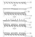
图2为本发明的模制成型方法的流程示意图。Fig. 2 is a schematic flow chart of the molding method of the present invention.
图3为本发明的模制成型方法中所述的平印显影方法的流程示意图。FIG. 3 is a schematic flow chart of the lithographic developing method described in the molding method of the present invention.
图4为本发明另一种实施方式的模制成型方法的流程示意图。Fig. 4 is a schematic flowchart of a molding method according to another embodiment of the present invention.
具体实施方式Detailed ways
本发明的实施例请参照图2所示,本发明的模制成型方法的步骤中,首先需要提供一基材35,此基材35是作为以微机电加工方法来制作一预模仁36的基础,较佳者,本发明所述的微机电加工方法可以为平印显影方法、精密放电加工方法或是激光加工方法等,为了解说方便,本实施例以平印显影方法作为本实用新型实施例中的微机电加工方法。The embodiment of the present invention please refer to Fig. 2 shown, in the step of molding method of the present invention, first need to provide a
请参照图3,为了制作出一预模仁36,需要在基材35上先形成一预模仁层34,较佳者,形成预模仁层34的方式可以是半导体方法中的沉积法等,但不以此为限;其中,预模仁层34需要为感旋光性物质所构成;提供一光掩模37,并将光掩模37置于预模仁层34上方,其光掩模37的图样是与所欲形成的预模仁36的图样相同;接下来,提供一光线38,照射在光掩模37上,由于光掩模37上的图样可以使光线部分穿过,进而照射在预模仁层34上,较佳者,光掩模37可以使光线穿过的部分,恰与所欲形成的预模仁36的图样相同,若是完全相反亦可,只要配合后的显影步骤所使用的显影剂即可;接下来进行一显影步骤,此显影步骤是以一显影剂将预模仁层34上被光线38照射过的部分(或是没有被光线38照射过的部分亦可)去除,如此,预模仁层34将被制作成为一预模仁36。Please refer to Fig. 3, in order to make a
上述的平印显影方法,可以制作出一高加工精密度的预模仁36,一般而言,由于平印显影方法属于半导体领域常用的技术,所以这样的平印显影方法可以轻易地制作出加工精密度在1毫米以下的预模仁36;除此之外,也可以采用如精密放电加工方法、激光加工方法或是快速原型技术加工方法等,其中精密放电加工方法是将一预模仁工件(图中未显示)置于一精密放电加工机具上,通过放电加工的程序后,同样可得致一加工精密度在1以下的预模仁36,但是其中的预模仁工件(图中未显示)的材质必须是金属;而激光加工方法是将一预模仁工件置于一激光加工机具上,运用高能量的激光光来加工预模仁工件(图中未显示),此方法不仅可以得致一加工精密度在1毫米以下的预模仁36,同时预模仁工件(图中未显示)基本上不需要限定其材质成分;而快速原型技术加工方法中包含有立体印刷成型法(Stereo Lithography Apparatus)、选择型激光烧结法(Selected Laser Sintering)、激光直接成型法(LaserEngineering Net Shaping)、三维喷涂黏接法(Three Dimensional Printing)、融熔沉积造型法(Fused Deposition Molding)、层合实体制造法(LaminatedObject Manufacturing)以及喷墨造型法(Inkjet Method)等,都可以制作出加工精密度在1毫米以下的预模仁36。The above-mentioned lithographic developing method can produce a
接下来,请再参照图2,当预模仁36制作完成后,可以将一模仁材料(图中未显示)形成于预模仁36上,并使模仁材料(图中未显示)成型为一模仁31,这可以应用例如微电铸方式,将基材35以及预模仁36置于微电铸机具中,利用微电铸原理将模仁材料(图中未显示)逐渐地填入预模仁36上,使成型为一模仁31;或是应用例如粉末冶金成型方式,将基材35以及预模仁36置于粉末冶金成型机具上,填入模仁材料(图中未显示)的粉末,经过压缩、烧结的程序后,亦可以成型为一模仁31。Next, please refer to FIG. 2 again. After the
接下来,再将模仁31与一模座32紧密结合而成为一模具1,再以该模具1针对一工件4进行一模制程序,较佳者,模制程序可以为一冲压程序,也就是将模具1固定于一冲压机具上,使模具1直接对于工件4冲压,即可使工件4形成预设的形状,但模制程序并不以此为限,例如挤压、压铸、锻造、板金以及射出成型等类似的模制程序,均可以获得相同的结果;其中,上述的模仁31的材质可以是镍钴、镍磷、镍钴磷、镍钨、镍铼、镍钯、镍铬、镍碳化硅磷、镍石墨、镍锰等二元或二元以上的镍基或是铬基合金所制成,其硬度在450HV(维氏硬度)以上,使可以制造出较为耐用的模仁31;此外,模仁31形成之后,亦可以针对模仁31或是整个模具1进行一后续处理,例如:热处理、表面镀膜处理、气体冷却处理以及液体冷却处理等,使模仁31的结构更为强化,更有利于模制程序的进行;其中,上述的表面镀膜处理是在模具1或是模仁31的表面,镀上一层保护膜,其保护膜的材质可已是氮化铝、氮化铝钛、氮化铬、碳化铝与类钻碳(DLC)等,其厚度可以在1至8微米(μm)之间,可以使模仁31的表面结构更为强化;可见上述的后续处理对于模具1在模制程序中非常重要,特别是针对加工精密度在1毫米以下工件4,由于其尺寸非常微小,模具1中的模仁31的结构强度若是不够,进行模制程序时模仁31很有可能因此损毁;较佳者,工件4的材质可以是铜金属、铜合金、铝金属、铝合金以及非金属,配合本发明的模制成型方法,其效果更为显著,但工件4的材质亦不应以此为限。Next, the
本发明另一实施方式请参照图4所示,本实施方式与上述的实施方式大致没有改变,但在制作模仁31时,可以仅仅制作出模仁31的突出部分即可,再利用基材35原本就与模仁31相互连接的特性,一并将模仁31与基材35与模座32紧密结合而成为一模具1,再以该模具1针对一工件4进行一模制程序,这样不仅可以达成与上述实施方式相同的功效,同时在将模仁材料(图中未显示)制作成模仁31时,节省了制作的过程以及原料。Please refer to FIG. 4 for another embodiment of the present invention. This embodiment is substantially unchanged from the above-mentioned embodiment. 35 is originally connected to the
依据上述的说明可知,本发明为了提高模仁的精密度,使可以制作出一高加工精密度的工件,以应现今产品轻薄短小的需求,特别设计出利用微机电加工方法来预先制作出一预模仁,由于微机电加工方法可以提供高加工精密度的特性,进而制作出高加工精密度的模仁,使达成制作出一高加工精密度的工件的目的,可见,本发明确实有其产业的价值。According to the above description, it can be seen that in order to improve the precision of the mold core, the present invention can produce a workpiece with high machining precision. The pre-mold core, because the micro-electromechanical processing method can provide the characteristics of high machining precision, and then produce a mold core with high machining precision, so as to achieve the purpose of making a workpiece with high machining precision, it can be seen that the present invention does have its own advantages. value of the industry.
以上所述仅为本发明的较佳实施例,上述实施例仅是用来说明而非用以限定本发明的申请专利范围,本发明的范畴是由以下的本申请的权利要求范围所界定。凡是依本发明申请专利权利要求范围所作的等效的改变或替换,皆应属本发明的涵盖范围。The above descriptions are only preferred embodiments of the present invention. The above embodiments are only used to illustrate but not to limit the scope of the present invention. The scope of the present invention is defined by the following claims of the present application. All equivalent changes or replacements made according to the scope of the patent claims of the present invention shall fall within the scope of the present invention.
Claims (13)
Translated fromChinesePriority Applications (1)
| Application Number | Priority Date | Filing Date | Title |
|---|---|---|---|
| CNB2004100685541ACN100450703C (en) | 2004-08-26 | 2004-08-26 | molding method |
Applications Claiming Priority (1)
| Application Number | Priority Date | Filing Date | Title |
|---|---|---|---|
| CNB2004100685541ACN100450703C (en) | 2004-08-26 | 2004-08-26 | molding method |
Publications (2)
| Publication Number | Publication Date |
|---|---|
| CN1739912A CN1739912A (en) | 2006-03-01 |
| CN100450703Ctrue CN100450703C (en) | 2009-01-14 |
Family
ID=36092521
Family Applications (1)
| Application Number | Title | Priority Date | Filing Date |
|---|---|---|---|
| CNB2004100685541AExpired - Fee RelatedCN100450703C (en) | 2004-08-26 | 2004-08-26 | molding method |
Country Status (1)
| Country | Link |
|---|---|
| CN (1) | CN100450703C (en) |
Families Citing this family (8)
| Publication number | Priority date | Publication date | Assignee | Title |
|---|---|---|---|---|
| KR101537619B1 (en) | 2009-09-09 | 2015-07-17 | 엘지전자 주식회사 | A production method of a stamper for an injection molding |
| KR20150001008A (en)* | 2013-06-26 | 2015-01-06 | 기아자동차주식회사 | Mathod Of Mass Production Mold By Press For Hot Stamping Cold Trim And Mass Production Mold By Press For Hot Stamping Cold Trim Using Thereof |
| CN105695834A (en)* | 2016-02-20 | 2016-06-22 | 杨鑫 | Female forming die |
| CN106696173A (en)* | 2017-01-11 | 2017-05-24 | 东莞市津舜康五金制品有限公司 | A male mold core of an injection mold and a production method of the male mold core of the injection mold |
| CN107877097A (en)* | 2017-11-03 | 2018-04-06 | 瑞声光电科技(常州)有限公司 | The processing method and process equipment of lens mould |
| CN108274083B (en)* | 2017-12-27 | 2019-06-07 | 中国科学院宁波材料技术与工程研究所 | A kind of method of the micro- texture in Electrolyzed Processing surface |
| FR3092103B1 (en)* | 2019-01-29 | 2022-08-05 | Netri | Process for manufacturing 3D microfluidic devices |
| CN115213633B (en)* | 2022-05-31 | 2024-01-30 | 东莞正广精密科技有限公司 | AG effect texture preparation method |
Citations (8)
| Publication number | Priority date | Publication date | Assignee | Title |
|---|---|---|---|---|
| US3498158A (en)* | 1968-06-07 | 1970-03-03 | Gti Corp | Steel embossing die and methods of making the same |
| US5079974A (en)* | 1991-05-24 | 1992-01-14 | Carnegie-Mellon University | Sprayed metal dies |
| JPH07109668B2 (en)* | 1986-10-24 | 1995-11-22 | キヤノン株式会社 | Method for manufacturing duplicate mold for precision molding |
| CN1311078A (en)* | 2000-02-28 | 2001-09-05 | 邓大仁 | Method for producing plastic optic full reflector mould |
| US20030042229A1 (en)* | 2001-08-30 | 2003-03-06 | Johnny Marcher | Method of making extrusion die with varying pin size |
| WO2003061356A1 (en)* | 2002-01-17 | 2003-07-24 | Elmicron Ag | Embossing die for fabricating high density interconnects and method for its fabrication |
| CN1434272A (en)* | 2002-01-21 | 2003-08-06 | 三菱电机株式会社 | Coder and coding-disk for coder and method for making coding-disk and mould thereof |
| JP7109668B2 (en)* | 2018-07-18 | 2022-07-29 | ボブスト リヨン | Doctor blade, doctor blade chamber and printing unit equipped with these |
- 2004
- 2004-08-26CNCNB2004100685541Apatent/CN100450703C/ennot_activeExpired - Fee Related
Patent Citations (8)
| Publication number | Priority date | Publication date | Assignee | Title |
|---|---|---|---|---|
| US3498158A (en)* | 1968-06-07 | 1970-03-03 | Gti Corp | Steel embossing die and methods of making the same |
| JPH07109668B2 (en)* | 1986-10-24 | 1995-11-22 | キヤノン株式会社 | Method for manufacturing duplicate mold for precision molding |
| US5079974A (en)* | 1991-05-24 | 1992-01-14 | Carnegie-Mellon University | Sprayed metal dies |
| CN1311078A (en)* | 2000-02-28 | 2001-09-05 | 邓大仁 | Method for producing plastic optic full reflector mould |
| US20030042229A1 (en)* | 2001-08-30 | 2003-03-06 | Johnny Marcher | Method of making extrusion die with varying pin size |
| WO2003061356A1 (en)* | 2002-01-17 | 2003-07-24 | Elmicron Ag | Embossing die for fabricating high density interconnects and method for its fabrication |
| CN1434272A (en)* | 2002-01-21 | 2003-08-06 | 三菱电机株式会社 | Coder and coding-disk for coder and method for making coding-disk and mould thereof |
| JP7109668B2 (en)* | 2018-07-18 | 2022-07-29 | ボブスト リヨン | Doctor blade, doctor blade chamber and printing unit equipped with these |
Also Published As
| Publication number | Publication date |
|---|---|
| CN1739912A (en) | 2006-03-01 |
Similar Documents
| Publication | Publication Date | Title |
|---|---|---|
| Pham et al. | Rapid prototyping and rapid tooling—the key enablers for rapid manufacturing | |
| Jain et al. | Micromanufacturing processes | |
| EP2991787B1 (en) | Investment casting utilizing flexible wax pattern tool for supporting a ceramic core along its length during wax injection | |
| RU2311984C2 (en) | Casting method and equipment for performing the same | |
| EP2509726B1 (en) | Investment casting utilizing flexible wax pattern tool | |
| Equbal et al. | Rapid tooling: A major shift in tooling practice | |
| Dimov et al. | Rapid tooling applications of the selective laser sintering process | |
| CN101780544A (en) | Method for forming refractory metal parts by using laser | |
| EP3427870B1 (en) | Three-dimensional molded object production method | |
| CN100450703C (en) | molding method | |
| Hussin et al. | The potential of metal epoxy composite (MEC) as hybrid mold inserts in rapid tooling application: A review | |
| Klocke et al. | Direct laser sintering of ceramics | |
| US11660661B2 (en) | Method for producing a refiner disc segment | |
| TWI290126B (en) | The method of die forming | |
| Yarlagadda et al. | Development of rapid tooling for sheet metal drawing using nickel electroforming and stereolithography processes | |
| CN113118457B (en) | A method of laser cladding and nitriding for preparing high hardness and high strength die | |
| JP2005048234A (en) | Metallic powder for metal light beam fabrication | |
| EP3323530A1 (en) | 3d printed watch dial | |
| Jain et al. | Micromanufacturing: an introduction | |
| JP2004211162A (en) | Method for producing die for press | |
| Wu et al. | Study on the fabricated feasibility of electrodes in EDM using rapid prototyping (RP) and investment casting technology | |
| JP4594486B2 (en) | Cavity forming mold manufacturing method and cavity forming mold | |
| CN113172875A (en) | A method of powder injection molding | |
| JP3865667B2 (en) | Electrode for electrical discharge machining and manufacturing method | |
| KR20050115738A (en) | Menufacturing method for metal casting moulds |
Legal Events
| Date | Code | Title | Description |
|---|---|---|---|
| C06 | Publication | ||
| PB01 | Publication | ||
| C10 | Entry into substantive examination | ||
| SE01 | Entry into force of request for substantive examination | ||
| C14 | Grant of patent or utility model | ||
| GR01 | Patent grant | ||
| CF01 | Termination of patent right due to non-payment of annual fee | Granted publication date:20090114 Termination date:20150826 | |
| EXPY | Termination of patent right or utility model |