CN100447467C - Microvalve integrated in flow channel - Google Patents
Microvalve integrated in flow channelDownload PDFInfo
- Publication number
- CN100447467C CN100447467CCNB2005100863223ACN200510086322ACN100447467CCN 100447467 CCN100447467 CCN 100447467CCN B2005100863223 ACNB2005100863223 ACN B2005100863223ACN 200510086322 ACN200510086322 ACN 200510086322ACN 100447467 CCN100447467 CCN 100447467C
- Authority
- CN
- China
- Prior art keywords
- micro
- flow channel
- scales
- flow
- valve
- Prior art date
- Legal status (The legal status is an assumption and is not a legal conclusion. Google has not performed a legal analysis and makes no representation as to the accuracy of the status listed.)
- Expired - Fee Related
Links
- 241000251730ChondrichthyesSpecies0.000claimsdescription3
- 230000003592biomimetic effectEffects0.000claims1
- 239000012530fluidSubstances0.000abstractdescription18
- 238000005516engineering processMethods0.000abstractdescription12
- 238000003786synthesis reactionMethods0.000abstractdescription2
- 238000000034methodMethods0.000description27
- XUIMIQQOPSSXEZ-UHFFFAOYSA-NSiliconChemical compound[Si]XUIMIQQOPSSXEZ-UHFFFAOYSA-N0.000description20
- 229910052710siliconInorganic materials0.000description20
- 239000010703siliconSubstances0.000description20
- 238000002360preparation methodMethods0.000description9
- 229920000642polymerPolymers0.000description8
- 235000012431wafersNutrition0.000description8
- 238000009792diffusion processMethods0.000description7
- 239000011521glassSubstances0.000description6
- 239000000463materialSubstances0.000description6
- 238000000206photolithographyMethods0.000description5
- VYPSYNLAJGMNEJ-UHFFFAOYSA-NSilicium dioxideChemical compoundO=[Si]=OVYPSYNLAJGMNEJ-UHFFFAOYSA-N0.000description4
- 238000000465mouldingMethods0.000description4
- 229910052814silicon oxideInorganic materials0.000description4
- 238000001312dry etchingMethods0.000description3
- 238000005530etchingMethods0.000description3
- 238000007731hot pressingMethods0.000description3
- 238000001053micromouldingMethods0.000description3
- 238000001039wet etchingMethods0.000description3
- 229910052581Si3N4Inorganic materials0.000description2
- 238000004458analytical methodMethods0.000description2
- 238000006243chemical reactionMethods0.000description2
- 239000002184metalSubstances0.000description2
- 238000005459micromachiningMethods0.000description2
- 230000003647oxidationEffects0.000description2
- 238000007254oxidation reactionMethods0.000description2
- HQVNEWCFYHHQES-UHFFFAOYSA-Nsilicon nitrideChemical compoundN12[Si]34N5[Si]62N3[Si]51N64HQVNEWCFYHHQES-UHFFFAOYSA-N0.000description2
- 230000007423decreaseEffects0.000description1
- 230000000694effectsEffects0.000description1
- 238000005538encapsulationMethods0.000description1
- 238000007667floatingMethods0.000description1
- 230000010354integrationEffects0.000description1
- 239000007788liquidSubstances0.000description1
- 238000001459lithographyMethods0.000description1
- 238000004519manufacturing processMethods0.000description1
- 239000011664nicotinic acidSubstances0.000description1
- 229920002120photoresistant polymerPolymers0.000description1
- 238000011160researchMethods0.000description1
- 238000012827research and developmentMethods0.000description1
- 238000007789sealingMethods0.000description1
- 239000000758substrateSubstances0.000description1
Images


Landscapes
- Micromachines (AREA)
Abstract
Translated fromChineseDescription
Translated fromChinese技术领域technical field
本发明属于微流体控制输运领域,具体涉及一种可直接集成于流道内的微型无源阀。The invention belongs to the field of microfluidic control transportation, in particular to a miniature passive valve that can be directly integrated in a flow channel.
背景技术Background technique
微型阀是微流体芯片内的关键部件,主要用于控制流体的流动方向及对流体流量进行定量控制,在微流控分析芯片内扮演了重要的角色。科技工作者们多年来一直致力于微型阀的研究与开发,目前可见的微型阀主要分为有源阀和无源阀:有源阀指利用致动器产生的致动力实现阀的关闭或切换操作,其主要的特点为致动力较强,阀的密封性较好,既可以用于单向阀也可以用于切换阀,但随之而来的局限性也非常明显,即此类微阀整体上的结构较为复杂,附加体积较大,加工和集成化的实现难度大,可靠性低,成本也相对较高;无源阀是指无需外来驱动力,仅利用流体本身参数的变化(如流动方向、流动压力等)即可实现阀的状态改变,此类微阀的体积大大减小,可靠性高,降低了工艺的复杂性和制作成本,易于和微流体系统集成。因此无源阀以其结构简单体积小,工艺难度和加工成本低,阀体材料选择范围广,可靠性高等比较优势,成为用于微流控分析芯片微阀研究的主要方向。The microvalve is a key component in the microfluidic chip. It is mainly used to control the flow direction of the fluid and quantitatively control the fluid flow. It plays an important role in the microfluidic analysis chip. Scientific and technological workers have been committed to the research and development of micro valves for many years. At present, the visible micro valves are mainly divided into active valves and passive valves: active valves refer to the use of the actuation force generated by the actuator to realize the closing or switching of the valve. Its main characteristics are strong actuation force and good sealing performance of the valve, which can be used for both one-way valve and switching valve, but the ensuing limitations are also very obvious, that is, this type of microvalve The overall structure is relatively complex, the additional volume is large, the realization of processing and integration is difficult, the reliability is low, and the cost is relatively high; the passive valve means that no external driving force is required, and only the change of the fluid itself is used (such as Flow direction, flow pressure, etc.) can realize the state change of the valve. The volume of this type of microvalve is greatly reduced, the reliability is high, the complexity of the process and the production cost are reduced, and it is easy to integrate with the microfluidic system. Therefore, passive valves have become the main direction of micro-valve research for microfluidic analysis chips due to their advantages such as simple structure, small size, low process difficulty and low processing cost, wide range of valve body material selection, and high reliability.
发明内容Contents of the invention
本发明提供一种直接集成于流道内部的微型无源阀,该微型阀具有结构简单,构思新颖,制备工艺简单等特点。The invention provides a miniature passive valve directly integrated in the flow channel. The microvalve has the characteristics of simple structure, novel concept, simple preparation process and the like.
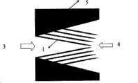
本发明的技术内容:一种集成于流道内的微型阀结构,它包括流道及连接在流道侧壁上的若干微鳞片结构,微鳞片彼此平行排布,并与流道侧壁成一定的倾角。顺着鳞片排布方向的流动为正向流动,鳞片对流体产生的阻力较小,为微型阀的开启方向(正方向)。逆着鳞片排布方向的流动为反向流动,鳞片对流体产生的阻力很大,为微型阀的关闭方向(反方向),集成在流道侧壁上的微鳞片是类似鲨鱼鳍的仿生结构。Technical content of the present invention: a micro-valve structure integrated in the flow channel, which includes a flow channel and a number of micro-scale structures connected to the side wall of the flow channel. inclination. The flow along the arrangement direction of the scales is the forward flow, and the resistance produced by the scales to the fluid is small, which is the opening direction (positive direction) of the micro-valve. The flow against the arrangement direction of the scales is the reverse flow. The resistance of the scales to the fluid is very large, which is the closing direction (reverse direction) of the micro-valve. The micro-scales integrated on the side wall of the flow channel are bionic structures similar to shark fins. .
微鳞片结构平行排布于流道的侧壁上,其中,流道侧壁上的每组微鳞片呈穿插或对称排布。The micro scale structures are arranged in parallel on the side wall of the flow channel, wherein each group of micro scales on the side wall of the flow channel is arranged interspersed or symmetrically.
流道为成一定锥角的扩散管结构或柱状结构,微流道可以为长方体、圆柱体、圆锥体、棱柱体、锥形台等。The flow channel is a diffusion tube structure or a columnar structure with a certain cone angle, and the micro flow channel can be a cuboid, cylinder, cone, prism, conical platform, etc.
本发明的技术效果:本发明利用化学合成或MEMS微加工工艺在微流体芯片的流道侧壁上加工出一些类似鳞片状的微结构,鳞片可以分为可动与不可动两类,流体顺着鳞片的方向流动时,鳞片对流体产生的阻力很小;而逆着鳞片方向,鳞片对流体产生的阻力很大,因此通过改变通道正反方向的流阻就实现了单向阀的作用,控制了液流的流动方向。这种微鳞片的加工工艺简单,可以和大多数的微流体系统集成,节约了成本且易于大批量生产。Technical effect of the present invention: the present invention uses chemical synthesis or MEMS micromachining technology to process some scale-like microstructures on the flow channel side wall of the microfluidic chip. The scales can be divided into two types: movable and immobile. When flowing in the direction of the scales, the resistance of the scales to the fluid is very small; while against the direction of the scales, the resistance of the scales to the fluid is very large, so the function of the one-way valve is realized by changing the flow resistance in the positive and negative directions of the channel. Controls the flow direction of the liquid flow. The processing technology of this kind of microscale is simple, can be integrated with most microfluidic systems, saves cost and is easy to mass-produce.
附图说明Description of drawings
下面结合附图,对本发明做出详细描述。The present invention will be described in detail below in conjunction with the accompanying drawings.
图1微通道内集成的微型可动鳞片阀俯视排布方式一;Fig. 1
图2圆锥体或圆锥台型微通道内集成微型可动鳞片阀俯视排布方式二;Fig. 2
图3微通道内部微型固定鳞片阀俯视排布方式三;Fig. 3
图4有一定夹角的扩散流道内部固定鳞片的俯视排布方式;Fig. 4 The top view arrangement of the fixed scales inside the diffusion channel with a certain angle;
图5微型可动鳞片阀的硅基加工工艺流程;Fig. 5 Silicon-based processing process flow of miniature movable scale valve;
图6微型可动鳞片阀的硅基加工工艺流程二;Figure 6 Silicon-based processing process flow two of the miniature movable scale valve;
图7微型固定鳞片工艺流程;Figure 7 micro-fixed scale process flow;
图8微模塑法制备微型可动鳞片阀工艺流程;Fig. 8 The process flow of preparing miniature movable scale valves by micromolding;
图9微模塑法制备固定鳞片的工艺流程。Fig. 9 The technological process of preparing fixed scales by micromolding.
具体实施方式Detailed ways
本发明提供了一系列由微鳞片结构1组成的微型阀,微型阀包括微流道5及连接在流道侧壁上的微型鳞片结构1,微鳞片1彼此平行排布,并与流道侧壁成一定的倾角,顺着鳞片的方向鳞片对流体产生的阻力小,而逆着鳞片的方向鳞片对流体产生较大的阻力,从而产生了正反向流量差,实现了阀的功能。The present invention provides a series of micro valves made up of
实施例一:阀体包括微流道5及连接在其侧壁上的平行排布的微型可动鳞片结构1,微流道可以是柱状结构,也可以是成一定锥角的扩散管结构,如图二所示,微鳞片1要顺着扩散的方向排布,这里微型可动鳞片1起到了阀片的作用,鳞片1的张合迎合流体内部的惯性流动,当流体顺着鳞片1的方向流动时,阻力很小,流动顺畅;与此相反的是当流体逆着鳞片1的方向流动时,鳞片1张开,流道的距离变窄,同时增加了逆向的扰动,使反向的流量减小,正向的流量大于逆向的流量,可以起到单向阀的作用。Embodiment 1: The valve body includes a micro-channel 5 and a parallel arrangement of
实施例二:阀体包括微流道5及连接在其垂直侧壁上的微型固定鳞片结构1,固定鳞片可以是类似鲨鱼鳍的结构,也可以是固定的片状结构,微鳞片结构彼此平行排布,其中,流道侧壁上的每组微鳞片彼此穿插或对称排布。如图三所示;微流道5可以是柱状的;微流道5两侧壁也可以成一定的角度,形成扩散管流道5(扩散方向的流量大,鳞片要顺着扩散的方向排布如图四所示,固定鳞片的主要作用是顺着流动方向尽量减少扰动,逆着流动方向增加扰动,从而改变了微流道的流阻特性,增大了效率。阀入口3进入的流量大于从出口4流出的流量,因此产生了正向的净流量,可以起到单向阀的作用。Embodiment 2: The valve body includes a micro-channel 5 and a
本发明中基于MEMS工艺加工的微型阀可根据其鳞片是否可动,分别采用以下方法制备:In the present invention, the micro-valve processed based on the MEMS process can be prepared by the following methods according to whether its scales are movable:
一、微型可动鳞片阀的硅基制备方法:1. Silicon-based preparation method of miniature movable scale valve:
(1)、如图5(a)所示,硅片7表面采用热氧化或CVD的方法淀积一层氧化层8,作为后续刻蚀的掩膜;(1), as shown in Figure 5 (a), the surface of the
(2)、如图5(b)所示,用掩膜板1对经步骤(1)氧化硅8进行第一次光刻,干法或湿法腐蚀的方法刻蚀出微鳞片阀结构的平面图;(2), as shown in Figure 5 (b), use the
(3)、如图5(c)所示,在硅片7上各向异性干法刻蚀微鳞片1和微流道结构5;(3), as shown in Figure 5(c), anisotropically dry etching the
(4)、如图5(d)所示,采用CVD的方法在刻蚀出的微结构上淀积一层氧化硅或氮化硅9,在后续的刻蚀反应中保护侧壁不被腐蚀;(4), as shown in Figure 5(d), a layer of silicon oxide or silicon nitride 9 is deposited on the etched microstructure by CVD to protect the sidewall from being corroded in the subsequent etching reaction ;
(5)、如图5(e)所示,干法各向异性刻蚀底面的氧化硅或氮化硅9;(5), as shown in Figure 5(e), dry anisotropically etch the silicon oxide or silicon nitride 9 on the bottom surface;
(6)、如图5(f)所示,SF6各向同性刻蚀,将细梁下面的硅掏空使其悬空;(6), as shown in Figure 5(f), SF6 isotropically etched, and the silicon under the thin beam is hollowed out to make it suspended;
(7)、如图5(g)所示,将整个结构表面剩余的氧化层都腐蚀掉;(7), as shown in Figure 5 (g), the remaining oxide layer on the entire structure surface is all corroded;
(8)、如图5(h)所示,玻璃10表面光刻用干法或湿法刻蚀的方法刻蚀出浅槽,使键合后整个微鳞片结构悬空;(8), as shown in Fig. 5 (h), the surface photolithography of glass 10 is etched out shallow groove with the method for dry method or wet etching, makes the whole micro-scale structure suspended after bonding;
(9)、如图5(i)所示,玻璃和硅片对准键合形成阀体结构;(9), as shown in Figure 5(i), the glass and the silicon wafer are aligned and bonded to form a valve body structure;
(10)、如图5(j)所示,硅片背面用干法或湿法刻蚀;(10), as shown in Figure 5(j), the back of the silicon wafer is etched by dry or wet methods;
(11)、如图5(k)所示,最后一次光刻,干法或湿法刻蚀出与外部流体管路连接的通孔11。(11), as shown in FIG. 5(k), the last photolithography, dry or wet etching to form the through
或采用另一种硅基制备方法制作微型可动悬浮鳞片阀:Or use another silicon-based preparation method to make miniature movable floating scale valves:
(1)如图6(a)所示,选用S0I硅片13(即在硅片一定深度的位置有一层氧化层12);(1) as shown in Fig. 6 (a), select
(2)、如图6(b)所示,光刻、刻蚀出微阀结构的平面图形;(2), as shown in Figure 6 (b), photolithography, etch out the planar figure of microvalve structure;
(3)、如图6(c)所示,腐蚀掉埋氧层,鳞片结构悬浮。(3) As shown in FIG. 6(c), the buried oxide layer is etched away, and the scale structure is suspended.
(4)、如图6(d)所示,在玻璃片10或其他盖片材料的表面腐蚀出浅槽;(4), as shown in Figure 6(d), etched shallow grooves on the surface of the glass sheet 10 or other cover sheet materials;
(5)、如图6(e)所示,玻璃和硅片对准键合形成阀体结构;(5), as shown in Figure 6(e), the glass and the silicon wafer are aligned and bonded to form a valve body structure;
二、微型不可动鳞片结构的硅基制备方法:2. The silicon-based preparation method of the micro immovable scale structure:
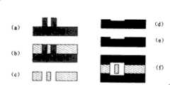
(1)、如图7(a)所示,硅片表面采用热氧化或CVD的方法淀积氧化层8,作为后续刻蚀的掩膜;(1), as shown in Figure 7 (a), the surface of the silicon wafer is deposited with an
(2)、如图7(b)所示,用掩膜版1对经步骤(1)的氧化硅光刻,刻蚀出微阀结构的平面图形;(2), as shown in Figure 7 (b), use
(3)、如图7(c)所示,各向异性刻蚀出反应流道及微型固定鳞片结构;(3), as shown in Figure 7(c), anisotropically etched the reaction channel and the micro-fixed scale structure;
(4)、如图7(d)所示,将硅片表面的氧化层腐蚀除去;(4), as shown in Figure 7 (d), the oxide layer on the surface of the silicon wafer is etched away;
(5)、如图7(e)所示,玻璃片与硅片对准键合形成阀体结构;(5), as shown in Figure 7(e), the glass sheet and the silicon sheet are aligned and bonded to form a valve body structure;
三、微模塑方法制备可动微鳞片结构:3. Preparation of movable micro-scale structure by micro-molding method:
(1)如图8(a)所示,制备模具14;模具制备方法包括采用厚胶光刻技术制备SU-8胶模具,采用LIGA技术制备金属模具,采用硅微机械加工技术制备硅模具;(1) As shown in Fig. 8(a), the mold 14 is prepared; the mold preparation method comprises the preparation of SU-8 plastic molds by thick rubber photolithography technology, the preparation of metal molds by LIGA technology, and the preparation of silicon molds by silicon micromachining technology;
(2)如图8(b)采用聚合物为泵体结构材料,利用步骤(1)所述模具,采用微模型技术制备三维结构的微鳞片聚合物或塑料结构15,微模型技术加工微鳞片结构的方法包括模塑成型法、真空热压法及LIGA技术;(2) As shown in Figure 8 (b), polymers are used as the pump body structural material, and the mold described in step (1) is used to prepare a three-dimensional micro-scale polymer or plastic structure 15 using micro-model technology, and the micro-scale technology is used to process the micro-scale Structural methods include molding, vacuum hot pressing and LIGA technology;
(3)如图8(c)所示,剥模形成聚合物等材料的微阀结构15;(3) as shown in Figure 8 (c), the microvalve structure 15 of materials such as polymer is formed by stripping mold;
(4)如图8(d)所示,采用聚合物、玻璃或硅片作为上封装片,分别在基片上腐蚀出微槽,可以采用湿法或干法刻蚀,聚合物基片采用微模塑法,热压法等在其表面相应的位置制备浅槽;(4) As shown in Figure 8(d), polymer, glass or silicon wafers are used as the upper package, and microgrooves are respectively etched on the substrate, which can be etched by wet or dry methods. Prepare shallow grooves at the corresponding positions on the surface by molding method, hot pressing method, etc.;
(5)如图8(e)、图8(f)所示,将封装片10与结构层对准键合形成阀体结构,可以采用聚合物键合或直接粘接的方法。(5) As shown in Fig. 8(e) and Fig. 8(f), the encapsulation sheet 10 and the structural layer are aligned and bonded to form a valve body structure, and a method of polymer bonding or direct bonding can be used.
四、采用模塑方法制备固定微鳞片结构:4. Prepare the fixed micro-scale structure by molding method:
(1)、如图9(a)所示,制备模具14,模具的材料可以是硅,光刻胶,聚合物、金属等;(1), as shown in Figure 9 (a), prepare mold 14, the material of mold can be silicon, photoresist, polymer, metal etc.;
(2)、如图9(b)所示,采用聚合物为泵体结构材料,利用步骤(1)所述模具,采用微模型技术制备三维结构的微鳞片聚合物或塑料结构15,微模型技术加工微鳞片结构的方法包括模塑成型法、真空热压法及LIGA技术;(2), as shown in Figure 9 (b), adopt the polymer as the pump body structural material, utilize the mold described in step (1), and adopt the micromodel technology to prepare the microscale polymer or plastic structure 15 of the three-dimensional structure, the micromodel The methods for processing the micro-scale structure include molding method, vacuum hot pressing method and LIGA technology;
(3)如图9(c)所示,剥模形成微鳞片结构。(3) As shown in Figure 9(c), the mold is peeled off to form a micro-scale structure.
(4)如图9(d)所示,与盖片键合形成阀体结构。(4) As shown in Figure 9(d), bond with the cover to form a valve body structure.
Claims (4)
Translated fromChinesePriority Applications (1)
| Application Number | Priority Date | Filing Date | Title |
|---|---|---|---|
| CNB2005100863223ACN100447467C (en) | 2005-08-31 | 2005-08-31 | Microvalve integrated in flow channel |
Applications Claiming Priority (1)
| Application Number | Priority Date | Filing Date | Title |
|---|---|---|---|
| CNB2005100863223ACN100447467C (en) | 2005-08-31 | 2005-08-31 | Microvalve integrated in flow channel |
Publications (2)
| Publication Number | Publication Date |
|---|---|
| CN1924417A CN1924417A (en) | 2007-03-07 |
| CN100447467Ctrue CN100447467C (en) | 2008-12-31 |
Family
ID=37817161
Family Applications (1)
| Application Number | Title | Priority Date | Filing Date |
|---|---|---|---|
| CNB2005100863223AExpired - Fee RelatedCN100447467C (en) | 2005-08-31 | 2005-08-31 | Microvalve integrated in flow channel |
Country Status (1)
| Country | Link |
|---|---|
| CN (1) | CN100447467C (en) |
Families Citing this family (12)
| Publication number | Priority date | Publication date | Assignee | Title |
|---|---|---|---|---|
| CN103006184B (en)* | 2013-01-16 | 2014-06-04 | 广州大学 | Nozzle with orifices switchable at two ends |
| DE102018105566B4 (en)* | 2018-03-12 | 2023-03-23 | Dr. Ing. H.C. F. Porsche Aktiengesellschaft | Flexible outlet valve |
| CN108757408B (en)* | 2018-06-28 | 2024-07-12 | 广州大学 | Valveless piezoelectric pump |
| CN108927233A (en)* | 2018-09-06 | 2018-12-04 | 广州大学 | A kind of no external force controls the microfluidic chip structure and preparation method thereof of unidirectional liquid transporting |
| CN110056694A (en)* | 2019-05-31 | 2019-07-26 | 深圳市宗泰电机有限公司 | Non-return valve |
| CN111828692B (en)* | 2020-08-11 | 2021-09-10 | 中国水利水电科学研究院 | Differential pressure runner air valve for preventing water hammer and water hammer preventing method |
| CN112196776A (en)* | 2020-10-04 | 2021-01-08 | 长春工业大学 | A novel valveless piezoelectric pump imitating fishbone bluff body |
| CN112240281B (en)* | 2020-10-16 | 2022-11-29 | 长春工业大学 | Composite piezoelectric pump with built-in sickle-shaped cavity |
| CN112984144A (en)* | 2021-01-25 | 2021-06-18 | 郑英翻 | Vertical scale type anti-spalling ball valve |
| CN112873840B (en)* | 2021-02-04 | 2024-08-23 | 西湖大学 | 3D printing nozzle, 3D printing nozzle assembly and 3D printing method |
| CN113058666B (en)* | 2021-03-17 | 2023-02-07 | 广西科技大学 | Micro-fluidic chip for detecting Alzheimer disease related protein NOD-like receptor 3 |
| CN113437393A (en)* | 2021-07-30 | 2021-09-24 | 中国科学院工程热物理研究所 | Cold drawing structure, battery cold drawing and battery thermal management system |
Citations (4)
| Publication number | Priority date | Publication date | Assignee | Title |
|---|---|---|---|---|
| DE4223019C1 (en)* | 1992-07-13 | 1993-11-18 | Fraunhofer Ges Forschung | Valveless micropump |
| DE29917547U1 (en)* | 1999-10-05 | 2000-01-05 | Armand, Gunter, 87647 Unterthingau | Single-flow flow device with piezo element or membrane |
| US20030185692A1 (en)* | 2002-03-27 | 2003-10-02 | Institute Of High Performance Computing | Valveless micropump |
| US20030235504A1 (en)* | 2002-06-20 | 2003-12-25 | The Regents Of The University Of California | Magnetohydrodynamic pump |
- 2005
- 2005-08-31CNCNB2005100863223Apatent/CN100447467C/ennot_activeExpired - Fee Related
Patent Citations (4)
| Publication number | Priority date | Publication date | Assignee | Title |
|---|---|---|---|---|
| DE4223019C1 (en)* | 1992-07-13 | 1993-11-18 | Fraunhofer Ges Forschung | Valveless micropump |
| DE29917547U1 (en)* | 1999-10-05 | 2000-01-05 | Armand, Gunter, 87647 Unterthingau | Single-flow flow device with piezo element or membrane |
| US20030185692A1 (en)* | 2002-03-27 | 2003-10-02 | Institute Of High Performance Computing | Valveless micropump |
| US20030235504A1 (en)* | 2002-06-20 | 2003-12-25 | The Regents Of The University Of California | Magnetohydrodynamic pump |
Also Published As
| Publication number | Publication date |
|---|---|
| CN1924417A (en) | 2007-03-07 |
Similar Documents
| Publication | Publication Date | Title |
|---|---|---|
| CN100447467C (en) | Microvalve integrated in flow channel | |
| Abgrall et al. | A novel fabrication method of flexible and monolithic 3D microfluidic structures using lamination of SU-8 films | |
| US8388908B2 (en) | Fluidic devices with diaphragm valves | |
| CN102678526B (en) | The travelling-wave-type Valveless Piezoelectric Micropump of multistage diffusion microchannel | |
| CN101907631B (en) | Double-liquid capillary micro-flow control valve in micro-flow control chip, and manufacturing method thereof | |
| WO2010118637A1 (en) | Microfluidic distribution device, production method and application thereof | |
| Han et al. | Multi-layer plastic/glass microfluidic systems containing electrical and mechanical functionality | |
| Lemke et al. | Fabrication of normally-closed bidirectional micropumps in silicon–polymer technology featuring photopatternable silicone valve lips | |
| Lee et al. | Quantitatively controlled nanoliter liquid manipulation using hydrophobic valving and control of surface wettability | |
| Hosokawa et al. | Hydrophobic Microcapillary Vent for Pneumatic Manipulaiton of Liquid in μtas | |
| JP2018130676A (en) | Microfluidic transportation structure where through hole and flow channel are integrated, and method for manufacturing the same | |
| CN101239285A (en) | A passive microfluidic mixer and packaging method thereof | |
| CN101893525A (en) | A centrifugal double-channel trace liquid quantitative sampling device and its manufacturing method | |
| CN100356071C (en) | Minitype jet pump and preparation method | |
| CN101716473B (en) | Chip-in micro-mixer and preparation method thereof | |
| Xu et al. | Process development and fabrication of application-specific microvalves | |
| Thuillier et al. | Development of a low cost hybrid Si/PDMS multi-layered pneumatic microvalve | |
| US20100327211A1 (en) | Method for the production of micro/nanofluidic devices for flow control and resulting device | |
| JP4934205B2 (en) | Micro valve mechanism | |
| CN200993249Y (en) | Non-movable-part micro valve | |
| Krusemark et al. | Micro ball valve for fluidic micropumps and gases | |
| CN100408852C (en) | MEMS V-shaped microvalve manufacturing method | |
| Hua et al. | A compact chemical-resistant microvalve array using Parylene membrane and pneumatic actuation | |
| Chen et al. | Floating-disk parylene micro check valve | |
| JP5402262B2 (en) | Microvalve and manufacturing method thereof |
Legal Events
| Date | Code | Title | Description |
|---|---|---|---|
| C06 | Publication | ||
| PB01 | Publication | ||
| C10 | Entry into substantive examination | ||
| SE01 | Entry into force of request for substantive examination | ||
| C14 | Grant of patent or utility model | ||
| GR01 | Patent grant | ||
| C17 | Cessation of patent right | ||
| CF01 | Termination of patent right due to non-payment of annual fee | Granted publication date:20081231 Termination date:20110831 |