CN100445737C - Analytical tool having opening in insulating film - Google Patents
Analytical tool having opening in insulating filmDownload PDFInfo
- Publication number
- CN100445737C CN100445737CCNB2004800172318ACN200480017231ACN100445737CCN 100445737 CCN100445737 CCN 100445737CCN B2004800172318 ACNB2004800172318 ACN B2004800172318ACN 200480017231 ACN200480017231 ACN 200480017231ACN 100445737 CCN100445737 CCN 100445737C
- Authority
- CN
- China
- Prior art keywords
- peristome
- dielectric film
- analyzer
- opening
- square crossing
- Prior art date
- Legal status (The legal status is an assumption and is not a legal conclusion. Google has not performed a legal analysis and makes no representation as to the accuracy of the status listed.)
- Expired - Lifetime
Links
Images


Classifications
- B—PERFORMING OPERATIONS; TRANSPORTING
- B01—PHYSICAL OR CHEMICAL PROCESSES OR APPARATUS IN GENERAL
- B01L—CHEMICAL OR PHYSICAL LABORATORY APPARATUS FOR GENERAL USE
- B01L3/00—Containers or dishes for laboratory use, e.g. laboratory glassware; Droppers
- B01L3/50—Containers for the purpose of retaining a material to be analysed, e.g. test tubes
- B01L3/502—Containers for the purpose of retaining a material to be analysed, e.g. test tubes with fluid transport, e.g. in multi-compartment structures
- B01L3/5027—Containers for the purpose of retaining a material to be analysed, e.g. test tubes with fluid transport, e.g. in multi-compartment structures by integrated microfluidic structures, i.e. dimensions of channels and chambers are such that surface tension forces are important, e.g. lab-on-a-chip
- B01L3/502707—Containers for the purpose of retaining a material to be analysed, e.g. test tubes with fluid transport, e.g. in multi-compartment structures by integrated microfluidic structures, i.e. dimensions of channels and chambers are such that surface tension forces are important, e.g. lab-on-a-chip characterised by the manufacture of the container or its components
- G—PHYSICS
- G01—MEASURING; TESTING
- G01N—INVESTIGATING OR ANALYSING MATERIALS BY DETERMINING THEIR CHEMICAL OR PHYSICAL PROPERTIES
- G01N27/00—Investigating or analysing materials by the use of electric, electrochemical, or magnetic means
- G01N27/26—Investigating or analysing materials by the use of electric, electrochemical, or magnetic means by investigating electrochemical variables; by using electrolysis or electrophoresis
- G01N27/28—Electrolytic cell components
- G01N27/30—Electrodes, e.g. test electrodes; Half-cells
- G01N27/327—Biochemical electrodes, e.g. electrical or mechanical details for in vitro measurements
- G01N27/3271—Amperometric enzyme electrodes for analytes in body fluids, e.g. glucose in blood
- G01N27/3272—Test elements therefor, i.e. disposable laminated substrates with electrodes, reagent and channels
- B—PERFORMING OPERATIONS; TRANSPORTING
- B01—PHYSICAL OR CHEMICAL PROCESSES OR APPARATUS IN GENERAL
- B01L—CHEMICAL OR PHYSICAL LABORATORY APPARATUS FOR GENERAL USE
- B01L2200/00—Solutions for specific problems relating to chemical or physical laboratory apparatus
- B01L2200/16—Reagents, handling or storing thereof
- B—PERFORMING OPERATIONS; TRANSPORTING
- B01—PHYSICAL OR CHEMICAL PROCESSES OR APPARATUS IN GENERAL
- B01L—CHEMICAL OR PHYSICAL LABORATORY APPARATUS FOR GENERAL USE
- B01L2300/00—Additional constructional details
- B01L2300/06—Auxiliary integrated devices, integrated components
- B01L2300/0627—Sensor or part of a sensor is integrated
- B01L2300/0645—Electrodes
- B—PERFORMING OPERATIONS; TRANSPORTING
- B01—PHYSICAL OR CHEMICAL PROCESSES OR APPARATUS IN GENERAL
- B01L—CHEMICAL OR PHYSICAL LABORATORY APPARATUS FOR GENERAL USE
- B01L2300/00—Additional constructional details
- B01L2300/08—Geometry, shape and general structure
- B01L2300/0809—Geometry, shape and general structure rectangular shaped
- B01L2300/0825—Test strips
- B—PERFORMING OPERATIONS; TRANSPORTING
- B01—PHYSICAL OR CHEMICAL PROCESSES OR APPARATUS IN GENERAL
- B01L—CHEMICAL OR PHYSICAL LABORATORY APPARATUS FOR GENERAL USE
- B01L2400/00—Moving or stopping fluids
- B01L2400/04—Moving fluids with specific forces or mechanical means
- B01L2400/0403—Moving fluids with specific forces or mechanical means specific forces
- B01L2400/0406—Moving fluids with specific forces or mechanical means specific forces capillary forces
- B—PERFORMING OPERATIONS; TRANSPORTING
- B01—PHYSICAL OR CHEMICAL PROCESSES OR APPARATUS IN GENERAL
- B01L—CHEMICAL OR PHYSICAL LABORATORY APPARATUS FOR GENERAL USE
- B01L2400/00—Moving or stopping fluids
- B01L2400/06—Valves, specific forms thereof
- B01L2400/0688—Valves, specific forms thereof surface tension valves, capillary stop, capillary break
- B—PERFORMING OPERATIONS; TRANSPORTING
- B01—PHYSICAL OR CHEMICAL PROCESSES OR APPARATUS IN GENERAL
- B01L—CHEMICAL OR PHYSICAL LABORATORY APPARATUS FOR GENERAL USE
- B01L2400/00—Moving or stopping fluids
- B01L2400/08—Regulating or influencing the flow resistance
- B01L2400/084—Passive control of flow resistance
- B01L2400/086—Passive control of flow resistance using baffles or other fixed flow obstructions
- B—PERFORMING OPERATIONS; TRANSPORTING
- B01—PHYSICAL OR CHEMICAL PROCESSES OR APPARATUS IN GENERAL
- B01L—CHEMICAL OR PHYSICAL LABORATORY APPARATUS FOR GENERAL USE
- B01L3/00—Containers or dishes for laboratory use, e.g. laboratory glassware; Droppers
- B01L3/50—Containers for the purpose of retaining a material to be analysed, e.g. test tubes
- B01L3/502—Containers for the purpose of retaining a material to be analysed, e.g. test tubes with fluid transport, e.g. in multi-compartment structures
- B01L3/5027—Containers for the purpose of retaining a material to be analysed, e.g. test tubes with fluid transport, e.g. in multi-compartment structures by integrated microfluidic structures, i.e. dimensions of channels and chambers are such that surface tension forces are important, e.g. lab-on-a-chip
- B01L3/502738—Containers for the purpose of retaining a material to be analysed, e.g. test tubes with fluid transport, e.g. in multi-compartment structures by integrated microfluidic structures, i.e. dimensions of channels and chambers are such that surface tension forces are important, e.g. lab-on-a-chip characterised by integrated valves
- B—PERFORMING OPERATIONS; TRANSPORTING
- B01—PHYSICAL OR CHEMICAL PROCESSES OR APPARATUS IN GENERAL
- B01L—CHEMICAL OR PHYSICAL LABORATORY APPARATUS FOR GENERAL USE
- B01L3/00—Containers or dishes for laboratory use, e.g. laboratory glassware; Droppers
- B01L3/52—Containers specially adapted for storing or dispensing a reagent
Landscapes
- Health & Medical Sciences (AREA)
- Chemical & Material Sciences (AREA)
- Life Sciences & Earth Sciences (AREA)
- General Health & Medical Sciences (AREA)
- Hematology (AREA)
- Analytical Chemistry (AREA)
- Chemical Kinetics & Catalysis (AREA)
- Physics & Mathematics (AREA)
- Electrochemistry (AREA)
- Molecular Biology (AREA)
- Biochemistry (AREA)
- Biophysics (AREA)
- General Physics & Mathematics (AREA)
- Immunology (AREA)
- Pathology (AREA)
- Dispersion Chemistry (AREA)
- Clinical Laboratory Science (AREA)
- Investigating Or Analysing Biological Materials (AREA)
Abstract
Description
Translated fromChinese技术领域technical field
本发明涉及在对试料(例如血液、尿或者唾液等生物化学试料)中的特定成分(例如血糖、胆固醇或者乳酸)进行分析时所使用的分析用具。The present invention relates to an analysis tool used for analyzing a specific component (such as blood sugar, cholesterol, or lactic acid) in a sample (such as a biochemical sample such as blood, urine, or saliva).
背景技术Background technique
在测定血液中葡萄糖浓度的情况下,作为一种简易的方法而采用一次性的葡萄糖传感器(例如参照专利文献1)。作为葡萄糖传感器,例如使用本发明的图9以及图10所示的葡萄糖传感器9,它采用可利用作用极90以及对极91来测定计算血糖值所需的响应电流值的构造。该葡萄糖传感器9的构造在于,通过在毛细管92中产生的毛细管力使血液移动,将血液与试药发生反应时产生的电子授受量作为响应电流值来进行测定。如图10以及图11所示,试药在绝缘膜93的开口部94中作为试药部95而被保持在基板96上。试药部95采用溶解性较高的材料而形成,以便当导入血液时试药可分散于血液中。如图9以及图10所示,毛细管92通过在基板96上经由形成切槽97a的间隔板97来层积盖体98的方式而形成。When measuring the glucose concentration in blood, a disposable glucose sensor is used as a simple method (for example, refer to Patent Document 1). As the glucose sensor, for example, the
血液在毛细管92中的移动速度(作用于血液的吸引力)由盖体98表面的可湿性或试药部95的溶解性而决定。盖体98的可湿性或试药部95的溶解性通常因时间或温度不同而降低。另一方面,如图10中明确所示,在基板96的表面上,通过在绝缘膜93上形成开口部94,而产生了台阶差99。因此,如图12A以及图12B所示,导入毛细管92中的血液B,在毛细管92中移动的过程中,有时会在台阶差99处停止。这种现象因毛细管92中吸引力的下降,即盖体98的可湿性或试药部95的溶解性的降低而经常发生。The moving speed of the blood in the capillary 92 (attractive force acting on the blood) is determined by the wettability of the surface of the
在台阶差99处停止移动的血液B,有时也保持该状态而停止流动,但是,有时血液B也会缓慢地移动或者血液B突然快速移动。如果血液B发生再移动现象,那么存在于作用极90或对极91的周围的电子传递物质的量(浓度)就会急剧变化,因此,在这种情况下,如图13中虚线所示,所测定的响应电流值会突然变大。此外,血液B的再移动现象并非在测定血糖值时才发生,而且发生血液B再移动现象的时间在每个葡萄糖传感器9中也不尽相同。因此,在发生血液B的再移动现象的葡萄糖传感器9中,响应电流值的测定重复性乃至将要计算的血糖值的重复性就会变差。The blood B that stops moving at the
专利文献1:(日本专利)特公平8-10208号公报Patent Document 1: (Japanese Patent) Japanese Patent Publication No. 8-10208
发明内容Contents of the invention
本发明的目的在于,在具备用来使试料移动的流路的分析用具中,可以长期稳定地供给试料并提高试料分析的重复性。It is an object of the present invention to improve the repeatability of sample analysis by stably supplying a sample over a long period of time in an analysis tool provided with a flow path for moving a sample.
本发明所提供的分析用具,其包括:基板、用来使试料沿着上述基板移动的流路、配置在上述流路内部的试药部、和具有规定用来形成上述试药部区域的开口部且覆盖上述基板的绝缘膜。上述绝缘膜还包括:与上述开口部相比而相对位于上述试料液移动的移动方向下游的一个以上的附设开口部。The analysis tool provided by the present invention includes: a substrate, a flow path for moving a sample along the substrate, a reagent part arranged inside the flow path, and a device having a predetermined area for forming the reagent part. The opening part and the insulating film covering the above-mentioned substrate. The insulating film may further include one or more additional openings located relatively downstream in a moving direction in which the sample liquid moves relative to the openings.
流路采用通过毛细管力而使试料移动的构造。The flow path adopts a structure that moves the sample by capillary force.
本发明的分析用具采用例如适合使用生物化学试料(例如血液、尿或者唾液)而作为试料的构造。The analytical tool of the present invention has a structure suitable for using, for example, a biochemical sample (for example, blood, urine, or saliva) as a sample.
本发明的分析用具还包括设置在基板上的第一电极以及第二电极。在采用这种构造的情况下,绝缘膜按照使第一电极以及第二电极的一部分露出的方式而覆盖第一电极以及第二电极。The analysis tool of the present invention further includes a first electrode and a second electrode disposed on the substrate. With such a structure, the insulating film covers the first electrode and the second electrode so that a part of the first electrode and the second electrode are exposed.
一个以上的附设开口部例如与开口部相连。在这种情况下,绝缘膜具有例如规定用来形成试药部的区域中上述移动方向下游边缘的限制边缘。The one or more additional openings are connected to the openings, for example. In this case, the insulating film has, for example, a limiting edge that defines the above-mentioned downstream edge in the moving direction in the region where the reagent portion is formed.
一个以上的开口部例如在与限制边缘中的上述移动方向垂直交叉的垂直交叉方向上邻接的部位而与开口部相连。The one or more openings are connected to the openings at positions adjacent to each other in a vertically intersecting direction perpendicularly intersecting the moving direction in the regulating edge, for example.
限制边缘形成沿着上述垂直交叉方向延伸的直线形状。此时,优选将限制边缘中的上述垂直交叉方向的尺寸设定为开口部中的上述垂直交叉方向的尺寸的60~95%。限制边缘也可以形成朝着上述移动方向的下游凹陷的曲线形状。The limiting edge is formed in a linear shape extending in the above-mentioned perpendicular intersecting direction. In this case, it is preferable to set the size of the above-mentioned perpendicular intersecting direction in the restriction edge to 60 to 95% of the above-mentioned dimension in the above-mentioned perpendicular intersecting direction in the opening. The restricting edge may also be formed in a curved shape concave toward the downstream of the above-mentioned moving direction.
绝缘膜可以包括例如以岛状存在并且具有限制边缘的岛部。岛部按照越朝着上述移动方向的下游,其宽度尺寸越小的方式形成。岛部的形状例如可以是三角形或半圆形。The insulating film may include, for example, an island portion existing in an island shape and having a limiting edge. The island portion is formed such that its width becomes smaller as it goes downstream in the moving direction. The shape of the island portion may be, for example, a triangle or a semicircle.
绝缘膜也可以包括以半岛状存在并且具有上述限制边缘的半岛部。此时,一个以上的附设开口部包括例如在半岛部上沿着宽度方向邻接而设的一对附设开口部。一对开口部例如也可以具有相同的宽度,此外,包括相对位于上述流向的上游的细宽部分、和与上述细宽部分相比而相对位于下游的粗宽部分。The insulating film may also include a peninsular portion that exists in a peninsula shape and has the above-mentioned limiting edge. In this case, the one or more additional openings include, for example, a pair of additional openings provided adjacent to each other in the width direction on the peninsula. The pair of openings may have the same width, for example, and include a narrow portion located relatively upstream in the flow direction and a thick portion located relatively downstream of the narrow portion.
一个以上的附设开口部也可以是至少其一部分沿着上述垂直交叉方向与开口部偏置。At least a part of the one or more additional openings may be offset from the openings along the above-mentioned perpendicular intersecting direction.
流路采用例如在基板上通过间隔板层积盖体的方式而形成。间隔板规定流路中的上述垂直交叉方向的尺寸,并且具有沿着上述垂直交叉的方向按照一定间隔而互相相对的一对相对面。此时,将一对相对面的间隔设定为大于开口部中的上述垂直交叉方向的尺寸。The flow path is formed, for example, by laminating a lid on a substrate with a spacer plate interposed therebetween. The partition plate regulates the dimension of the above-mentioned perpendicular intersecting direction in the flow path, and has a pair of opposing surfaces facing each other at regular intervals along the above-mentioned perpendicular intersecting direction. At this time, the distance between the pair of facing surfaces is set to be larger than the above-mentioned dimension perpendicular to the intersecting direction in the opening portion.
如果流路例如采用通过毛细管力使试料移动的构造,那么盖体具有用来排出流路内部气体的排气口。在这种情况下,与排气口中的上述移动方向的最上游位置相比,开口部中上述移动方向的最下游位置相对位于上游一侧。If the flow path has a structure in which the sample is moved by, for example, capillary force, the cover has an exhaust port for exhausting gas inside the flow path. In this case, the most downstream position in the movement direction in the opening portion is located on the upstream side relative to the most upstream position in the movement direction in the exhaust port.
附图说明Description of drawings
图1是本发明所涉及的一例葡萄糖传感器的整体立体图。FIG. 1 is an overall perspective view of an example of a glucose sensor according to the present invention.
图2是图1所示的葡萄糖传感器的分解立体图。Fig. 2 is an exploded perspective view of the glucose sensor shown in Fig. 1 .
图3是沿着图1中的III-III线的截面图。FIG. 3 is a cross-sectional view along line III-III in FIG. 1 .
图4是在取下图1所示的葡萄糖传感器的盖体与间隔板的状态下其端部的平面图。Fig. 4 is a plan view of an end portion of the glucose sensor shown in Fig. 1 in a state where a cover and a partition plate are removed.
图5是相当于图4所示的葡萄糖传感器中的止动部的其它例子的平面图。Fig. 5 is a plan view corresponding to another example of a stopper in the glucose sensor shown in Fig. 4 .
图6是相当于图4所示的葡萄糖传感器中第二开口部的其它例子的平面图。Fig. 6 is a plan view corresponding to another example of the second opening in the glucose sensor shown in Fig. 4 .
图7是第一实施例中的响应电流值的测定结果的曲线图。FIG. 7 is a graph showing measurement results of response current values in the first example.
图8是比较例1中的响应电流值的测定结果的曲线图。FIG. 8 is a graph showing measurement results of response current values in Comparative Example 1. FIG.
图9是现有技术的葡萄糖传感器的整体立体图。Fig. 9 is an overall perspective view of a conventional glucose sensor.
图10是沿着图9中X-X线的截面图。Fig. 10 is a cross-sectional view along line X-X in Fig. 9 .
图11是在取下图9所示的葡萄糖传感器的盖体与间隔板的状态下其端部的平面图。Fig. 11 is a plan view of an end portion of the glucose sensor shown in Fig. 9 with its cover and partition plate removed.
图12是说明现有技术的葡萄糖传感器中存在的问题的示意图,图12A是相当于图10的截面图,图12B是相当于图11的截面图。FIG. 12 is a schematic diagram illustrating problems in the conventional glucose sensor, FIG. 12A is a cross-sectional view corresponding to FIG. 10 , and FIG. 12B is a cross-sectional view corresponding to FIG. 11 .
图13是在现有技术的葡萄糖传感器中所测定的响应电流值随时间变化的一例曲线图。Fig. 13 is a graph showing an example of changes in response current value over time measured in a conventional glucose sensor.
具体实施方式Detailed ways
图1以及图3所示的葡萄糖传感器X采用一次性的结构设计,将它安装在浓度测定装置(省略图示)中用来测定血糖值。该葡萄糖传感器X具有在长矩形状的基板1上经由间隔板2而层积盖体3的形态。在葡萄糖传感器X中,通过各个构件1~3来规定沿着基板1的纵向而延伸的毛细管4。毛细管4利用毛细管现象,使从导入口40导入的血液沿着基板1的纵向(图中的N1方向)移动,并保存导入的血液。The glucose sensor X shown in Fig. 1 and Fig. 3 adopts a disposable structural design, and it is installed in a concentration measuring device (not shown) to measure blood sugar level. This glucose sensor X has a form in which a
间隔板2用来规定从基板1的上面10至盖体3的下面30之间的距离,即规定毛细管4的高度,例如,它可以使用双面胶来构成。该间隔板2具有顶端部开口的切槽20。该切槽20用来规定毛细管4的宽度,切槽20的顶端的开口部分构成导入口40,它用来将血液导入毛细管4的内部。切槽20具有沿着基板1的横向(N3、N4)按照一定间隔相对的一对相对面20a。The
盖体3具有贯通孔31。该贯通孔31用来将毛细管4内部的气体排出外部。盖体3的临近毛细管4的表面成为亲水性较高的部位。这种盖体3可以采用如下方式而形成,例如整个盖体3使用维尼纶(Vinylon)或者高结晶化PVA等可湿性高的材料形成,或者通过在临近毛细管4的表面实施亲水处理而形成。亲水处理可以通过照射紫外线或者涂敷卵磷脂等界面活性剂来进行。The
如图2以及图3明确所示,基板1使用PET(聚对苯二甲酸乙二醇酯)等绝缘树脂材料形成,在它的上面10形成作用极11、对极12、绝缘膜13以及试药部14。作用极11以及对极12的大部分沿着基板1的纵向(图中的N1、N2方向)延伸,其端部11a、12a沿着基板1的横向(图中的N3、N4方向)延伸。作用极11以及对极12的另一个端部11b、12b构成与设置在浓度测定装置(省略图示)中的端子接触的端子部。作用极11以及对极12可以通过使用导电性复写油墨(Carbon Ink)的丝网印刷而形成。As clearly shown in FIGS. 2 and 3, the
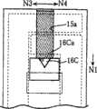
绝缘膜13用来保护作用极11以及对极12免受水分或灰尘等污染。与基板1的表面或者作用极11以及对极12相比,该绝缘膜13的疏水性更高,在它表面形成例如100~120度的接触角。这种绝缘膜13可以采用如下方式形成:通过在涂敷包含憎水性(拨水性)高的材料的墨水(INK)之后并使其干燥而形成,或者通过使包含憎水剂(拨水剂)的紫外线硬化树脂硬化而形成。如图2以及图4明确所示,绝缘膜13以露出作用极11以及对极12的端部11a、12a、11b、12b的方式而覆盖作用极11以及对极12的大部分。该绝缘膜13具有第一开口部15a以及一对第二开口部15b。The insulating
在形成基板1中的作用极11以及对极12的端部11a、12a的区域内,第一开口部15a规定用来形成试药部14的区域。该第一开口部15a形成沿着基板1的纵向(图中的N1、N2方向)延伸的长矩形状,它的宽度W1比间隔板2中的切槽20的两个相对面20a的间隔W2小。The
一对第二开口部15b用来促进血液在毛细管4的内部的移动距离超过第一开口部15a。这些第二开口部15b,在从第一开口部15a朝着N1方向(在毛细管4中血液移动方向的下游)的部位,形成沿着基板1的横向N3、N4排列的矩形状。各个第二开口部15b与第一开口部15a相对,在基板1的横向(图中的N3、N4方向)具有偏置的部分,同时它与第一开口部15a相连。在一对第二开口部15b之间设置止动部16。该止动部16构成绝缘膜13的一部分,并形成半岛形状。在该止动部16的边缘16a的两边,第二开口部15b与第一开口部15a相连。其结果在于,第二开口部15b中N3、N4方向的尺寸,比第一开口部15a与第二开口部15b之间的连接部分中N3、N4方向的尺寸大。The pair of
如后所述,止动部16的作用在于,当在第一开口部15a中形成试药部14时,防止用于形成试药部14的试药液沿着N1方向过度扩散。这种作用实际上通过限制边缘16a来实现。该限制边缘16a规定第一开口部15a与止动部16的交界,它位于从盖体3的贯通孔31的边缘31a偏向导入口40的一侧(N2方向一侧)。限制边缘16a的尺寸例如被设定为第一开口部15a中横向(图中的N3、N4方向)尺寸的60~95%的长度。采用这种方式的原因在于,如果限制边缘16a的尺寸小于第一开口部15a的N3、N4方向的尺寸并且不符合上述范围,那么就无法有效地防止上述试药液朝着N1方向的扩散,最终导致试药液流入第二开口部15b中。反之,如果限制边缘16a的尺寸与第一开口部15a的N3、N4方向的尺寸之差过小,那么,当把血液导入毛细管4内时,就无法使血液有效地移动至第二开口部15b。As will be described later, the
在绝缘膜13的第一开口部15a中设置有试药部14,以便连接作用极11以及对极12的端部11a、12a,该试药部14包含电子传递物质以及相对少量的氧化还原酶。该试药部14形成为血液容易溶解其中的多孔质的固体状。因此,当把血液导入毛细管4中时,通过试药部14所起的作用,血液容易沿着基板1的表面移动,或者在毛细管4的内部构筑成一个包括电子传递物质、氧化还原酶以及葡萄糖的液相反应体系。A
作为氧化还原酶例如可以使用GOD或GDH,典型的是使用PQQGDH。作为电子传递物质例如可以使用钌(Ru)配位化合物或铁配位化合物,典型的是使用[Ru(NH3)6]Cl3或K3[Fe(CN)6]。As the oxidoreductase, for example, GOD or GDH can be used, and PQQGDH is typically used. As the electron transport substance, for example, a ruthenium (Ru) complex or an iron complex can be used, typically [Ru(NH3 )6 ]Cl3 or K3 [Fe(CN)6 ].
试药部14例如可以采用在向第一开口部15a中分注包含电子传递物质以及氧化还原酶的试药液之后并使试药液干燥的方式而形成。当向第一开口部15a中分注试药液的情况下,试药液将在第一开口部15a中扩散,它的扩散在第一开口部15a中的基板1的横向(图中的N3、N4方向)的两个边缘以及止动部16的边缘16a处受到限制。因此,不仅可以有选择地向第一开口部15a中分注试药液,还可以在第一开口部15a上有选择地形成试药部14。The
下面,对使用葡萄糖传感器X的葡萄糖浓度的测定方法进行说明。Next, a method of measuring the glucose concentration using the glucose sensor X will be described.
在葡萄糖传感器X中,将该葡萄糖传感器X安装在浓度测定装置(省略图示)中之后,通过葡萄糖传感器X的导入口40向毛细管4供给血液,这样就可以在浓度测定装置(省略图示)中自动测定血糖值。In the glucose sensor X, after installing the glucose sensor X in the concentration measuring device (not shown), blood is supplied to the capillary 4 through the inlet 40 of the glucose sensor X, so that the concentration measuring device (not shown) Automatically determine the blood glucose level.
在将葡萄糖传感器X安装在浓度测定装置(省略图示)中的情况下,葡萄糖传感器X的作用极11以及对极12接触浓度测定装置(省略图示)的端子。另一方面,当向毛细管4供给血液时,通过在毛细管4中产生的毛细管现象,血液从导入口40朝着贯通孔31前进。在血液前进的过程中,血液溶解于试药部14中,于是,就在毛细管4的内部构筑成一个液相反应体系。因此,可以利用作用极11以及对极12向该液相反应体系施加电压或者测定施加电压时的响应电流值。When the glucose sensor X is attached to a concentration measuring device (not shown), the working
在液相反应体系中,例如氧化还原酶与血液中的葡萄糖发生特异性反应而从葡萄糖中导出电子,该电子被供给电子传递物质(electroncarrier),电子传递物质为还原型。当利用作用极11以及对极12向液相反应体系施加电压时,电子从还原型的电子传递物质供给作用极11。因此,在浓度测定装置中,例如可以将供给作用极11的电子量作为响应电流值来进行测定。在浓度测定装置(省略图示)中,根据开始向毛细管4供血经过一定时间之后所测定的响应电流值来计算葡萄糖。In the liquid phase reaction system, for example, oxidoreductase specifically reacts with glucose in blood to extract electrons from glucose, and the electrons are supplied to an electron carrier, which is a reduced form. When a voltage is applied to the liquid-phase reaction system by the working
在葡萄糖传感器X中,绝缘膜13的第一开口部15a与第二开口部15b相连。因此,在毛细管4中的基板1的表面,沿着血液的前进方向N1而形成未被绝缘膜13所覆盖的部分,即形成与绝缘膜13相比亲水性更高的区域。因此,在葡萄糖传感器X中,由于血液可以在上述亲水性高的区域中积极主动地前进,因此,可以使血液从第一开口部15a积极主动地流向第二开口部15b。而且,由于第二开口部15b的宽度比第一开口部15a与第二开口部15b之间的连接部分的尺寸大,因此,血液就从第一开口部15a积极主动地流向第二开口部15b。结果在于,血液在第一开口部15a的边缘即止动部16的边缘16a处停止前进,或者抑制血液的再次移动。因此,存在于作用极11的端部11a周围的电子传递物质的量(浓度)发生急剧变化的可能性也会减少,所测定的响应电流值更接近本应获得的数值。因此,在葡萄糖传感器X中,可以提高响应电流值的测定重复性,进而提高所计算的血糖值的重复性。当盖体3的可湿性(亲水性)或试药部14的溶解性随时间变化或者温度条件不同而下降,并且毛细管4中的吸引力降低时,就可以获得这种效果。In the glucose sensor X, the
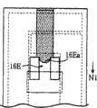
本发明并非局限于上述实施方式,它可以进行各种各样的设计更改。例如,如图5A所示,可以形成将止动部16B与绝缘膜13分离的矩形的岛式隔离区。此外,在止动部与绝缘膜分离的情况下,它的形态并非局限于矩形,也可以如图5B或者图5C所示的止动部16C、16D而形成三角形或半圆形或者其它的形状。在图5B或者图5C所示的例子中,直线形状的限制边缘16Ca、16Da限制与第一开口部15a的交界部分,同时,越朝着作为血液流向的N1方向,其宽度方向N3、N4的尺寸越小。因此,当血液从第一开口部15a流向第二开口部15b时,血液就很容易沿着N1方向绕过止动部16C、16D的后侧。结果在于,即使在设置了止动部16C、16D的情况下,仍可以准确地使血液流向第二开口部15b。The present invention is not limited to the above-mentioned embodiments, and various design changes are possible. For example, as shown in FIG. 5A , a rectangular island-type isolation region separating the
但是,由于止动部必须按照如下方式形成,即在形成试药部时能够适当地抑制试药液流入第二开口部中,因此,它的限制边缘除了形成上述直线形状之外,也可以如图5D所示的止动部16E的限制边缘16Ea而形成沿着箭头N1方向凹陷的曲线形状。在图5D中以形成半岛形状的止动部16E为例,但这种曲线的限制边缘也可以适用于止动部与绝缘膜分离而形成岛式隔离区的构造。However, since the stopper portion must be formed in such a way that the reagent solution can be properly restrained from flowing into the second opening when the reagent portion is formed, its limiting edge may be formed as described above in addition to the linear shape. The limit edge 16Ea of the
此外,第二开口部也可以是图6A~图6D所示的形态。在图6A以及图6B中,表示形成一个第二开口部15Fb、15Gb的例子。在图6C中表示第二开口部15Hb并未沿着箭头N3、N4方向与第一开口部15a偏置的例子。在图6D中,表示第二开口部15Ib具有与第一开口部15a连接的细宽部分15Ib′、以及位于与细宽部分15Ib′相比而偏向血液流向的下游(N1方向)的粗宽部分15Ib″的例子。当然,除了图6A~图6D所示的形态之外,第二开口部也可以设计更改为其它的形态。In addition, the second opening may be in the form shown in FIGS. 6A to 6D . In FIGS. 6A and 6B , an example in which one second opening 15Fb, 15Gb is formed is shown. FIG. 6C shows an example in which the second opening 15Hb is not offset from the
本发明并非局限于测定血液中的葡萄糖浓度这种构造的葡萄糖传感器,它也可以适用于其它的分析用具,例如适用于用来测定血液中的葡萄糖以外的成分(胆固醇或乳酸等),或者用来分析血液以外的试料(尿或唾液等)的分析用具。此外,本发明并非局限于利用电极法的分析用具,它也可以适用于采用光学方法对试料中的特定成分进行分析的分析用具。The present invention is not limited to the glucose sensor with the structure of measuring the glucose concentration in the blood, and it can also be applied to other analytical tools, for example, it is suitable for measuring components other than glucose in the blood (cholesterol or lactic acid, etc.), or using Analytical tools for analyzing samples (urine, saliva, etc.) other than blood. In addition, the present invention is not limited to an analysis tool using an electrode method, but can also be applied to an analysis tool that analyzes a specific component in a sample using an optical method.
实施例Example
下面,对本发明所涉及的葡萄糖传感器能够在测定响应电流值时改善重复性并精确地测定葡萄糖浓度的情况进行证明。Next, it will be demonstrated that the glucose sensor according to the present invention can measure the glucose concentration accurately by improving the repeatability of the measurement of the response current value.
第一实施例first embodiment
在本实施例中,采用图1至图4所示的葡萄糖传感器X的构造作为葡萄糖传感器的基本构造,并采用图6C所示的第二开口部15Hb的构造。下面,对于与本实施例中所使用的葡萄糖传感器相关的其它条件进行说明。In this embodiment, the configuration of the glucose sensor X shown in FIGS. 1 to 4 is adopted as the basic configuration of the glucose sensor, and the configuration of the second opening portion 15Hb shown in FIG. 6C is adopted. Next, other conditions related to the glucose sensor used in this example will be described.
基板1使用PET(商品名称“E-22”,东丽株式会社制造)而形成。作用极11以及对极12,通过使用复写油墨的丝网印刷方法而形成10μm的厚度。绝缘膜13通过使用憎水性(拨水性)高的抗蚀油墨的丝网印刷方法而形成20μm的厚度、105度的接触角。绝缘膜13的第一开口部15a的长度L1为2.5mm、宽度W1为1.7mm(参照图2以及图6C)。在第一实施例中所使用的葡萄糖传感器的止动部的宽度W3为0.6mm(参照图6C)。试药部包含作为电子传递物质的[Ru(NH3)6]Cl3(同仁化学研究所制造“LM722”)以及作为氧化还原酶的PQQGDH(商品名称“PQQ-GDH”,东洋纺株式会社制造)。当毛细管4中充满血液并且电子传递物质与氧化还原酶溶解于血液中时,它们在血液中的浓度分别为4vol%与3U。使用双面胶(商品名称“550PS5”,积水化学工业株式会社制造)作为间隔板2。盖体使用维尼纶(商品名称“VINYLON SHEET VF-LH”,东セロ株式会社)制成。毛细管4的宽度W2(参照图1以及图2)为1.8mm、长度L2为3.2mm、高度H2(参照图3)为45μm。The
在本实施例中,根据响应电流值的时间流程变化(Time Course)对重复性进行评估。响应电流值的时间流程变化,使用葡萄糖浓度为400mg/dL并且Hct值为42%的全血进行10次测定。自开始供血5秒钟之后开始向作用极与对极之间施加电压值为200毫伏的电压,并自施加电压开始,每隔100msec对响应电流值进行时效测定。此处使用两种葡萄糖传感器,一种是制造完成之后的葡萄糖传感器;另一种是将制造完成的葡萄糖传感器在温度50℃、相对湿度大约为2%的环境下保存30天之后的葡萄糖传感器。分别在图7A以及图7B中表示葡萄糖传感器制造初期以及从开始制造30天之后的葡萄糖传感器的时间流程变化的测定结果。In this embodiment, the repeatability is evaluated according to the time course change (Time Course) of the response current value. In response to the time course change of the current value, 10 measurements were performed using whole blood having a glucose concentration of 400 mg/dL and an Hct value of 42%. A voltage of 200 millivolts was applied between the working electrode and the
比较例1Comparative example 1
在本比较例中,除了使用没有第二开口部(参照图9至图11)的葡萄糖传感器之外,其余均按照与第一实施例相同的方式来测定响应电流值的时间流程变化。分别在图8A以及图8B中表示葡萄糖传感器制造初期以及从开始制造30天之后的葡萄糖传感器的时间流程变化的测定结果。In this comparative example, except for using a glucose sensor without a second opening (see FIGS. 9 to 11 ), the time course change of the response current value was measured in the same manner as in the first embodiment. 8A and 8B respectively show the measurement results of the time course change of the glucose sensor at the initial stage of manufacturing the glucose sensor and 30 days after the start of manufacturing.
由图7A以及图8A可知,在制造完成之后的葡萄糖传感器中,第一实施例以及比较例1的葡萄糖传感器二者均没有出现时间流程变化紊乱。另一方面,由图7B以及图8B可知,在保存30天之后的葡萄糖传感器中,在第一实施例中响应电流值的时间流程变化未出现紊乱,与此相反,在比较例1的葡萄糖传感器中则出现了紊乱。因此,如第一实施例的葡萄糖传感器所述,通过设置与第一开口部连通的第二开口部并设置止动部,这样不仅可以在第一开口部恰当地形成试药部分,同时还可以按照良好的重复性来测定将要测定的响应电流值。此外,在温度50℃、相对湿度大约为2%的恶劣环境下保存葡萄糖传感器,这样,在第一实施例的葡萄糖传感器中,就可以长期以良好的重复性来测定响应电流值。因此,在第一实施例的葡萄糖传感器中,可以长期精确地测定响应电流值甚至葡萄糖浓度。It can be seen from FIG. 7A and FIG. 8A that, in the glucose sensor after the completion of manufacture, neither the glucose sensor of the first embodiment nor the glucose sensor of the comparative example 1 has a disturbance of the time course change. On the other hand, as can be seen from FIG. 7B and FIG. 8B , in the glucose sensor stored for 30 days, there is no disorder in the time course change of the response current value in the first embodiment. On the contrary, in the glucose sensor of Comparative Example 1 There was a disorder in it. Therefore, as described in the glucose sensor of the first embodiment, by providing the second opening communicated with the first opening and providing the stopper, not only can the reagent portion be properly formed in the first opening, but also The response current value to be measured is determined with good repeatability. In addition, the glucose sensor is stored in a harsh environment with a temperature of 50° C. and a relative humidity of about 2%. In this way, in the glucose sensor of the first embodiment, the response current value can be measured with good repeatability over a long period of time. Therefore, in the glucose sensor of the first embodiment, the response current value and even the glucose concentration can be accurately measured over a long period of time.
Claims (18)
Applications Claiming Priority (2)
| Application Number | Priority Date | Filing Date | Title |
|---|---|---|---|
| JP2003175248 | 2003-06-19 | ||
| JP175248/2003 | 2003-06-19 |
Publications (2)
| Publication Number | Publication Date |
|---|---|
| CN1809747A CN1809747A (en) | 2006-07-26 |
| CN100445737Ctrue CN100445737C (en) | 2008-12-24 |
Family
ID=33534815
Family Applications (1)
| Application Number | Title | Priority Date | Filing Date |
|---|---|---|---|
| CNB2004800172318AExpired - LifetimeCN100445737C (en) | 2003-06-19 | 2004-06-15 | Analytical tool having opening in insulating film |
Country Status (5)
| Country | Link |
|---|---|
| US (2) | US7699967B2 (en) |
| EP (1) | EP1635170B1 (en) |
| JP (1) | JP4480672B2 (en) |
| CN (1) | CN100445737C (en) |
| WO (1) | WO2004113903A1 (en) |
Families Citing this family (22)
| Publication number | Priority date | Publication date | Assignee | Title |
|---|---|---|---|---|
| US20060091006A1 (en)* | 1999-11-04 | 2006-05-04 | Yi Wang | Analyte sensor with insertion monitor, and methods |
| WO2003025559A1 (en)* | 2001-09-11 | 2003-03-27 | Arkray, Inc. | Measuring instrument, installation body, and density measurer |
| US7905999B2 (en)* | 2005-06-08 | 2011-03-15 | Abbott Laboratories | Biosensor strips and methods of preparing same |
| JP2007017169A (en)* | 2005-07-05 | 2007-01-25 | Yamaha Corp | Biosensor, component detection apparatus, and human stress measurement method |
| WO2007133457A2 (en) | 2006-05-08 | 2007-11-22 | Bayer Healthcare Llc | Electrochemical test sensor with reduced sample volume |
| KR100890988B1 (en)* | 2007-10-29 | 2009-03-31 | 주식회사 아이센스 | Electrochemical biosensor equipped with sample introduction part that can uniformly introduce small amount of sample |
| EP2304445B1 (en)* | 2008-07-09 | 2020-06-10 | Micropoint Bioscience Inc | Analytical cartridge with fluid flow control |
| CN101623660B (en)* | 2008-07-09 | 2014-04-02 | 微点生物技术有限公司 | Analysis spraying canister having liquid stream control |
| US8012428B2 (en) | 2008-10-30 | 2011-09-06 | Lifescan Scotland, Ltd. | Analytical test strip with minimal fill-error sample viewing window |
| US20100112612A1 (en)* | 2008-10-30 | 2010-05-06 | John William Dilleen | Method for determining an analyte using an analytical test strip with a minimal fill-error viewing window |
| NZ591742A (en) | 2008-11-07 | 2012-12-21 | Hoffmann La Roche | Fine-grained filler substances for photometric reaction films |
| US8061004B2 (en)* | 2009-08-20 | 2011-11-22 | Roche Diagnostics Operations, Inc. | Method of manufacturing a test strip |
| JP5102334B2 (en)* | 2010-06-25 | 2012-12-19 | 日本電波工業株式会社 | Sensing device |
| JP5813171B2 (en)* | 2013-05-02 | 2015-11-17 | アークレイ株式会社 | Analytical tool, manufacturing method thereof, and measuring device using the same |
| DE102013210138A1 (en)* | 2013-05-30 | 2014-12-04 | Boehringer Ingelheim Vetmedica Gmbh | Method for generating a plurality of measuring ranges on a chip and chip with measuring ranges |
| CN103412026A (en)* | 2013-08-30 | 2013-11-27 | 江苏鱼跃医疗设备股份有限公司 | Biosensor and manufacturing method thereof |
| TWI609182B (en)* | 2016-11-04 | 2017-12-21 | 五鼎生物技術股份有限公司 | Glucose measuring device andapparatus |
| KR102024608B1 (en)* | 2017-01-11 | 2019-09-24 | 엘지전자 주식회사 | Sensor |
| US11448611B2 (en) | 2019-07-03 | 2022-09-20 | Medtronic Minimed, Inc. | Structurally reinforced sensor and method for manufacturing the same |
| EP4130752A4 (en)* | 2020-03-24 | 2024-04-17 | Kyocera Corporation | FLOW PATH DEVICE |
| US12345618B2 (en) | 2020-03-24 | 2025-07-01 | Kyocera Corporation | Flow path device for separating target particles in a fluid |
| EP4116705A1 (en)* | 2021-07-05 | 2023-01-11 | ARKRAY, Inc. | Biosensor |
Citations (5)
| Publication number | Priority date | Publication date | Assignee | Title |
|---|---|---|---|---|
| US5582697A (en)* | 1995-03-17 | 1996-12-10 | Matsushita Electric Industrial Co., Ltd. | Biosensor, and a method and a device for quantifying a substrate in a sample liquid using the same |
| CN2287722Y (en)* | 1997-03-04 | 1998-08-12 | 北京大学化学与分子工程学院 | Biological electric chemical sensor |
| US5985116A (en)* | 1996-12-24 | 1999-11-16 | Matsushita Electric Industrial Co., Ltd. | Biosensor |
| WO2002032559A1 (en)* | 2000-10-19 | 2002-04-25 | Inverness Medical Limited | Paste, which can undergo screen printing, for producing a porous polymer membrane for a biosensor |
| CN1405557A (en)* | 2002-10-28 | 2003-03-26 | 中国科学院长春应用化学研究所 | Method for preparing capacitor biological sensor |
Family Cites Families (13)
| Publication number | Priority date | Publication date | Assignee | Title |
|---|---|---|---|---|
| DE68924026T3 (en)* | 1988-03-31 | 2008-01-10 | Matsushita Electric Industrial Co., Ltd., Kadoma | BIOSENSOR AND ITS MANUFACTURE. |
| US5320732A (en)* | 1990-07-20 | 1994-06-14 | Matsushita Electric Industrial Co., Ltd. | Biosensor and measuring apparatus using the same |
| JPH0810208A (en) | 1994-06-30 | 1996-01-16 | Toshiba Corp | Dishwasher |
| JP3102627B2 (en) | 1995-03-17 | 2000-10-23 | 松下電器産業株式会社 | Biosensor, quantitative method and quantitative device using the same |
| JP3375040B2 (en) | 1997-07-29 | 2003-02-10 | 松下電器産業株式会社 | Substrate quantification method |
| US6129823A (en)* | 1997-09-05 | 2000-10-10 | Abbott Laboratories | Low volume electrochemical sensor |
| CA2305922C (en)* | 1999-08-02 | 2005-09-20 | Bayer Corporation | Improved electrochemical sensor design |
| US6645359B1 (en)* | 2000-10-06 | 2003-11-11 | Roche Diagnostics Corporation | Biosensor |
| KR20030038664A (en)* | 2000-07-14 | 2003-05-16 | 라이프스캔, 인코포레이티드 | Electrochemical method for measuring chemical reaction rates |
| ATE543091T1 (en)* | 2001-08-01 | 2012-02-15 | Arkray Inc | ANALYZER, ANALYZER |
| KR100475634B1 (en)* | 2001-12-24 | 2005-03-15 | 주식회사 아이센스 | Biosensor equipped with sample introducing part which enables quick introduction of a small amount of sample |
| US6946299B2 (en)* | 2002-04-25 | 2005-09-20 | Home Diagnostics, Inc. | Systems and methods for blood glucose sensing |
| US6743635B2 (en)* | 2002-04-25 | 2004-06-01 | Home Diagnostics, Inc. | System and methods for blood glucose sensing |
- 2004
- 2004-06-15CNCNB2004800172318Apatent/CN100445737C/ennot_activeExpired - Lifetime
- 2004-06-15EPEP04745902Apatent/EP1635170B1/ennot_activeExpired - Lifetime
- 2004-06-15WOPCT/JP2004/008348patent/WO2004113903A1/enactiveApplication Filing
- 2004-06-15JPJP2005507215Apatent/JP4480672B2/ennot_activeExpired - Fee Related
- 2004-06-15USUS10/560,015patent/US7699967B2/enactiveActive
- 2009
- 2009-11-10USUS12/615,829patent/US8617368B2/ennot_activeExpired - Lifetime
Patent Citations (5)
| Publication number | Priority date | Publication date | Assignee | Title |
|---|---|---|---|---|
| US5582697A (en)* | 1995-03-17 | 1996-12-10 | Matsushita Electric Industrial Co., Ltd. | Biosensor, and a method and a device for quantifying a substrate in a sample liquid using the same |
| US5985116A (en)* | 1996-12-24 | 1999-11-16 | Matsushita Electric Industrial Co., Ltd. | Biosensor |
| CN2287722Y (en)* | 1997-03-04 | 1998-08-12 | 北京大学化学与分子工程学院 | Biological electric chemical sensor |
| WO2002032559A1 (en)* | 2000-10-19 | 2002-04-25 | Inverness Medical Limited | Paste, which can undergo screen printing, for producing a porous polymer membrane for a biosensor |
| CN1405557A (en)* | 2002-10-28 | 2003-03-26 | 中国科学院长春应用化学研究所 | Method for preparing capacitor biological sensor |
Non-Patent Citations (1)
| Title |
|---|
| 以聚邻苯二胺修饰的镀铂玻碳电极为基底的葡萄糖传感以聚邻苯二胺修饰的镀铂玻碳电极为基底的葡萄糖传感以聚邻苯二胺修饰的镀铂玻碳电极为基底的葡萄糖传感以聚邻苯二胺修饰的镀铂玻碳电极为基底的葡萄糖传感以聚邻苯二胺修饰的镀铂玻碳电极为基底的葡萄糖传感器. 纪学峰,章咏华.应用化学,第10卷第2期. 1993* |
Also Published As
| Publication number | Publication date |
|---|---|
| US20100051456A1 (en) | 2010-03-04 |
| JPWO2004113903A1 (en) | 2006-08-03 |
| CN1809747A (en) | 2006-07-26 |
| US8617368B2 (en) | 2013-12-31 |
| JP4480672B2 (en) | 2010-06-16 |
| EP1635170B1 (en) | 2012-09-26 |
| US7699967B2 (en) | 2010-04-20 |
| WO2004113903A1 (en) | 2004-12-29 |
| EP1635170A1 (en) | 2006-03-15 |
| US20060131171A1 (en) | 2006-06-22 |
| EP1635170A4 (en) | 2011-02-16 |
Similar Documents
| Publication | Publication Date | Title |
|---|---|---|
| CN100445737C (en) | Analytical tool having opening in insulating film | |
| CN101014851B (en) | Electrochemical cell and method for producing an electrochemical cell | |
| US7955554B2 (en) | Analytical tool | |
| CN100541192C (en) | Glucose Sensor with Vent | |
| CA2654499A1 (en) | Capillary flow control in a flow channel | |
| EP2664913A1 (en) | Biosensor | |
| JP4942763B2 (en) | Method for forming a multi-layer test sensor | |
| CN100480695C (en) | Electrochemical screen printing electrode sensing test piece and manufacturing method thereof | |
| JP4674283B2 (en) | Analytical tool and manufacturing method thereof | |
| JP4385208B2 (en) | Analytical tool and manufacturing method thereof | |
| CN113167760B (en) | Systems and methods for electronic gate features in electrochemical test strips | |
| KR20160044504A (en) | Analytical test strip having cantilevered contacts | |
| US20180277419A1 (en) | Sensor array with anti-diffusion region(s) to extend shelf life | |
| CN101842697B (en) | Analytical tool and manufacture method thereof | |
| CN201075107Y (en) | biochemical sensor | |
| CN115586058A (en) | Biosensor with a sensor element | |
| TW201501694A (en) | Analytical test strip with capillary sample-receiving chambers separated by a physical barrier island |
Legal Events
| Date | Code | Title | Description |
|---|---|---|---|
| C06 | Publication | ||
| PB01 | Publication | ||
| C10 | Entry into substantive examination | ||
| SE01 | Entry into force of request for substantive examination | ||
| C14 | Grant of patent or utility model | ||
| GR01 | Patent grant | ||
| CX01 | Expiry of patent term | Granted publication date:20081224 | |
| CX01 | Expiry of patent term |