CN100441982C - Device and method for preventing accumulation of liquid refrigerant in air conditioner - Google Patents
Device and method for preventing accumulation of liquid refrigerant in air conditionerDownload PDFInfo
- Publication number
- CN100441982C CN100441982CCNB2004100749100ACN200410074910ACN100441982CCN 100441982 CCN100441982 CCN 100441982CCN B2004100749100 ACNB2004100749100 ACN B2004100749100ACN 200410074910 ACN200410074910 ACN 200410074910ACN 100441982 CCN100441982 CCN 100441982C
- Authority
- CN
- China
- Prior art keywords
- compressor
- valve
- refrigerant
- liquid
- liquid recovery
- Prior art date
- Legal status (The legal status is an assumption and is not a legal conclusion. Google has not performed a legal analysis and makes no representation as to the accuracy of the status listed.)
- Expired - Fee Related
Links
Images


Classifications
- F—MECHANICAL ENGINEERING; LIGHTING; HEATING; WEAPONS; BLASTING
- F25—REFRIGERATION OR COOLING; COMBINED HEATING AND REFRIGERATION SYSTEMS; HEAT PUMP SYSTEMS; MANUFACTURE OR STORAGE OF ICE; LIQUEFACTION SOLIDIFICATION OF GASES
- F25B—REFRIGERATION MACHINES, PLANTS OR SYSTEMS; COMBINED HEATING AND REFRIGERATION SYSTEMS; HEAT PUMP SYSTEMS
- F25B31/00—Compressor arrangements
- F25B31/002—Lubrication
- F25B31/004—Lubrication oil recirculating arrangements
- F—MECHANICAL ENGINEERING; LIGHTING; HEATING; WEAPONS; BLASTING
- F25—REFRIGERATION OR COOLING; COMBINED HEATING AND REFRIGERATION SYSTEMS; HEAT PUMP SYSTEMS; MANUFACTURE OR STORAGE OF ICE; LIQUEFACTION SOLIDIFICATION OF GASES
- F25B—REFRIGERATION MACHINES, PLANTS OR SYSTEMS; COMBINED HEATING AND REFRIGERATION SYSTEMS; HEAT PUMP SYSTEMS
- F25B13/00—Compression machines, plants or systems, with reversible cycle
- F—MECHANICAL ENGINEERING; LIGHTING; HEATING; WEAPONS; BLASTING
- F25—REFRIGERATION OR COOLING; COMBINED HEATING AND REFRIGERATION SYSTEMS; HEAT PUMP SYSTEMS; MANUFACTURE OR STORAGE OF ICE; LIQUEFACTION SOLIDIFICATION OF GASES
- F25B—REFRIGERATION MACHINES, PLANTS OR SYSTEMS; COMBINED HEATING AND REFRIGERATION SYSTEMS; HEAT PUMP SYSTEMS
- F25B2313/00—Compression machines, plants or systems with reversible cycle not otherwise provided for
- F25B2313/001—Compression machines, plants or systems with reversible cycle not otherwise provided for with two or more accumulators
- F—MECHANICAL ENGINEERING; LIGHTING; HEATING; WEAPONS; BLASTING
- F25—REFRIGERATION OR COOLING; COMBINED HEATING AND REFRIGERATION SYSTEMS; HEAT PUMP SYSTEMS; MANUFACTURE OR STORAGE OF ICE; LIQUEFACTION SOLIDIFICATION OF GASES
- F25B—REFRIGERATION MACHINES, PLANTS OR SYSTEMS; COMBINED HEATING AND REFRIGERATION SYSTEMS; HEAT PUMP SYSTEMS
- F25B2400/00—General features or devices for refrigeration machines, plants or systems, combined heating and refrigeration systems or heat-pump systems, i.e. not limited to a particular subgroup of F25B
- F25B2400/07—Details of compressors or related parts
- F25B2400/075—Details of compressors or related parts with parallel compressors
- F—MECHANICAL ENGINEERING; LIGHTING; HEATING; WEAPONS; BLASTING
- F25—REFRIGERATION OR COOLING; COMBINED HEATING AND REFRIGERATION SYSTEMS; HEAT PUMP SYSTEMS; MANUFACTURE OR STORAGE OF ICE; LIQUEFACTION SOLIDIFICATION OF GASES
- F25B—REFRIGERATION MACHINES, PLANTS OR SYSTEMS; COMBINED HEATING AND REFRIGERATION SYSTEMS; HEAT PUMP SYSTEMS
- F25B2400/00—General features or devices for refrigeration machines, plants or systems, combined heating and refrigeration systems or heat-pump systems, i.e. not limited to a particular subgroup of F25B
- F25B2400/19—Pumping down refrigerant from one part of the cycle to another part of the cycle, e.g. when the cycle is changed from cooling to heating, or before a defrost cycle is started
- F—MECHANICAL ENGINEERING; LIGHTING; HEATING; WEAPONS; BLASTING
- F25—REFRIGERATION OR COOLING; COMBINED HEATING AND REFRIGERATION SYSTEMS; HEAT PUMP SYSTEMS; MANUFACTURE OR STORAGE OF ICE; LIQUEFACTION SOLIDIFICATION OF GASES
- F25B—REFRIGERATION MACHINES, PLANTS OR SYSTEMS; COMBINED HEATING AND REFRIGERATION SYSTEMS; HEAT PUMP SYSTEMS
- F25B2500/00—Problems to be solved
- F25B2500/27—Problems to be solved characterised by the stop of the refrigeration cycle
- F—MECHANICAL ENGINEERING; LIGHTING; HEATING; WEAPONS; BLASTING
- F25—REFRIGERATION OR COOLING; COMBINED HEATING AND REFRIGERATION SYSTEMS; HEAT PUMP SYSTEMS; MANUFACTURE OR STORAGE OF ICE; LIQUEFACTION SOLIDIFICATION OF GASES
- F25B—REFRIGERATION MACHINES, PLANTS OR SYSTEMS; COMBINED HEATING AND REFRIGERATION SYSTEMS; HEAT PUMP SYSTEMS
- F25B2600/00—Control issues
- F25B2600/02—Compressor control
- F25B2600/021—Inverters therefor
- F—MECHANICAL ENGINEERING; LIGHTING; HEATING; WEAPONS; BLASTING
- F25—REFRIGERATION OR COOLING; COMBINED HEATING AND REFRIGERATION SYSTEMS; HEAT PUMP SYSTEMS; MANUFACTURE OR STORAGE OF ICE; LIQUEFACTION SOLIDIFICATION OF GASES
- F25B—REFRIGERATION MACHINES, PLANTS OR SYSTEMS; COMBINED HEATING AND REFRIGERATION SYSTEMS; HEAT PUMP SYSTEMS
- F25B2600/00—Control issues
- F25B2600/25—Control of valves
- F25B2600/2519—On-off valves
- F—MECHANICAL ENGINEERING; LIGHTING; HEATING; WEAPONS; BLASTING
- F25—REFRIGERATION OR COOLING; COMBINED HEATING AND REFRIGERATION SYSTEMS; HEAT PUMP SYSTEMS; MANUFACTURE OR STORAGE OF ICE; LIQUEFACTION SOLIDIFICATION OF GASES
- F25B—REFRIGERATION MACHINES, PLANTS OR SYSTEMS; COMBINED HEATING AND REFRIGERATION SYSTEMS; HEAT PUMP SYSTEMS
- F25B2700/00—Sensing or detecting of parameters; Sensors therefor
- F25B2700/21—Temperatures
- F25B2700/2106—Temperatures of fresh outdoor air
- F—MECHANICAL ENGINEERING; LIGHTING; HEATING; WEAPONS; BLASTING
- F25—REFRIGERATION OR COOLING; COMBINED HEATING AND REFRIGERATION SYSTEMS; HEAT PUMP SYSTEMS; MANUFACTURE OR STORAGE OF ICE; LIQUEFACTION SOLIDIFICATION OF GASES
- F25B—REFRIGERATION MACHINES, PLANTS OR SYSTEMS; COMBINED HEATING AND REFRIGERATION SYSTEMS; HEAT PUMP SYSTEMS
- F25B2700/00—Sensing or detecting of parameters; Sensors therefor
- F25B2700/21—Temperatures
- F25B2700/2115—Temperatures of a compressor or the drive means therefor
- F25B2700/21152—Temperatures of a compressor or the drive means therefor at the discharge side of the compressor
- Y—GENERAL TAGGING OF NEW TECHNOLOGICAL DEVELOPMENTS; GENERAL TAGGING OF CROSS-SECTIONAL TECHNOLOGIES SPANNING OVER SEVERAL SECTIONS OF THE IPC; TECHNICAL SUBJECTS COVERED BY FORMER USPC CROSS-REFERENCE ART COLLECTIONS [XRACs] AND DIGESTS
- Y02—TECHNOLOGIES OR APPLICATIONS FOR MITIGATION OR ADAPTATION AGAINST CLIMATE CHANGE
- Y02B—CLIMATE CHANGE MITIGATION TECHNOLOGIES RELATED TO BUILDINGS, e.g. HOUSING, HOUSE APPLIANCES OR RELATED END-USER APPLICATIONS
- Y02B30/00—Energy efficient heating, ventilation or air conditioning [HVAC]
- Y02B30/70—Efficient control or regulation technologies, e.g. for control of refrigerant flow, motor or heating
Landscapes
- Engineering & Computer Science (AREA)
- Physics & Mathematics (AREA)
- Mechanical Engineering (AREA)
- Thermal Sciences (AREA)
- General Engineering & Computer Science (AREA)
- Air Conditioning Control Device (AREA)
- Compression-Type Refrigeration Machines With Reversible Cycles (AREA)
Abstract
Translated fromChinese
Description
Translated fromChinese技术领域technical field
本发明涉及一种空调设备,并且更加特别地涉及一种用于防止空调的液体制冷剂积存的设备及方法。The present invention relates to an air conditioner, and more particularly, to an apparatus and method for preventing liquid refrigerant accumulation of an air conditioner.
背景技术Background technique
通常,空气调节单元是一种用于对有限的室内空间,包括居室空间、餐馆、或办公室进行空气调节或加热的装置。近来,多体空气调节单元(multiair handling unit)的发展提出了通过同时对每个房间进行空气调节或加热来更加有效地对多房间室内空间进行空气调节或加热。In general, an air conditioning unit is a device for air conditioning or heating a limited indoor space, including living room spaces, restaurants, or offices. More recently, the development of multiair handling units has proposed more efficient air conditioning or heating of multi-room indoor spaces by air conditioning or heating each room simultaneously.
空气调节单元常进行制冷循环。在制冷循环中,当工作流体经过压缩机时,室外热交换器(冷凝器)、膨胀阀、以及室内热交换器(蒸发器),其将热量从低温制冷剂转移至高温制冷剂,从而进行空气调节或加热或空气调节/加热。Air-conditioning units often perform a refrigeration cycle. In the refrigeration cycle, when the working fluid passes through the compressor, the outdoor heat exchanger (condenser), the expansion valve, and the indoor heat exchanger (evaporator), which transfer heat from the low-temperature refrigerant to the high-temperature refrigerant, thereby Air conditioning or heating or air conditioning/heating.
图1为现有技术制冷循环的示意图。Fig. 1 is a schematic diagram of a refrigeration cycle in the prior art.
如图1所示,现有技术的制冷循环包括具有用于将制冷剂压缩为高温、高压制冷剂蒸汽的多个压缩机的压缩单元2a、2b;用于将油从由压缩单元2a、2b排出的制冷剂中分离出来的多个油分离器4a、4b;设置在压缩单元2a、2b排出一侧并改变制冷模式或加热模式中的制冷剂流动的四通阀6;用于在制冷模式下,使制冷剂与室外空气进行热交换从而将制冷剂凝结为中温、高压液体制冷剂的室外热交换器8;用于使通过室外热交换器8的制冷剂通过(在加热模式中压缩制冷剂)的膨胀阀10;用于使通过EEV 21和膨胀阀21的低温、低压制冷剂与室内空气进行热交换的室内热交换器22;以及用于从通过室内热交换器22的制冷剂中分离液体制冷剂并仅向压缩单元2a、2b提供制冷剂蒸汽的收集器12。As shown in Figure 1, the refrigeration cycle of the prior art includes compression units 2a, 2b with multiple compressors for compressing refrigerant into high-temperature, high-pressure refrigerant vapor; A plurality of oil separators 4a, 4b separated from the discharged refrigerant; a four-way valve 6 provided on the discharge side of the compression unit 2a, 2b and changing the refrigerant flow in the cooling mode or heating mode; Next, the outdoor heat exchanger 8 that makes the refrigerant exchange heat with the outdoor air to condense the refrigerant into a medium-temperature, high-pressure liquid refrigerant; agent) expansion valve 10; an indoor heat exchanger 22 for heat-exchanging the low-temperature, low-pressure refrigerant passing through the EEV 21 and the expansion valve 21 with indoor air; A collector 12 that separates the liquid refrigerant and supplies only the refrigerant vapor to the compression units 2a, 2b.
此处,压缩单元2a、2b包括以固定速度旋转的定速压缩机2a和旋转速度可变的变频压缩机2b,因此可以改善空气调节性能,且还可以改变空气调节能力。定速压缩机2a中和变频压缩机2b内是将要与制冷剂循环的油,从而改善压缩机的可靠性和工作效率。Here, the compression units 2a, 2b include a fixed speed compressor 2a rotating at a fixed speed and an inverter compressor 2b whose rotation speed is variable, so air conditioning performance can be improved and air conditioning capability can also be varied. In the fixed speed compressor 2a and in the variable frequency compressor 2b is the oil to be circulated with the refrigerant, thereby improving the reliability and working efficiency of the compressor.
另外,第一油分离器4a安装在定速压缩机2a的后端,而第二油分离器4b安装在变频压缩机2b的后端,其每一个从由各个压缩机2a、2b排出的制冷剂中分离出油,并使制冷剂再次循环至每个压缩机2a、2b。In addition, the first oil separator 4a is installed at the rear end of the fixed speed compressor 2a, and the second oil separator 4b is installed at the rear end of the inverter compressor 2b, each of which is discharged from the refrigerant discharged from the respective compressors 2a, 2b. The oil is separated from the refrigerant and the refrigerant is recirculated to each compressor 2a, 2b.
在制冷循环安装有多个压缩机的情况下,在每个压缩机内循环的油的量相等对于压缩机更加有效地工作十分重要。为此,在定速压缩机2a和变频压缩机20之间的下端安装用于使压力相等的压力调节管14,从而保持压缩机2a、2b内的油水平。In a case where a refrigeration cycle is installed with multiple compressors, it is important for the compressors to work more efficiently by equalizing the amount of oil circulating in each compressor. To this end, a pressure regulating pipe 14 for equalizing the pressure is installed at the lower end between the fixed speed compressor 2a and the inverter compressor 20, thereby maintaining the oil level in the compressors 2a, 2b.
在施加电源时,变频压缩机2b响应输入信号立即改变rpm(转数/分),并调节在制冷循环中循环的制冷剂流量,使其满足制冷能力。在变频压缩机2b无法满足制冷能力需求的情况下,定速压缩机2a再调整在制冷循环中循环的制冷剂流量,以提高制冷效率。When power is applied, the inverter compressor 2b immediately changes rpm (revolutions per minute) in response to an input signal, and adjusts the flow rate of refrigerant circulating in the refrigeration cycle to meet the refrigeration capacity. In the case that the frequency conversion compressor 2b cannot meet the refrigeration capacity requirement, the fixed speed compressor 2a adjusts the flow rate of the refrigerant circulating in the refrigeration cycle to improve the refrigeration efficiency.
另外,止回阀5a、5b分别设置在压缩机2a、2b的排出侧,以防止制冷剂倒流。即,当压缩机2a、2b仅有一个工作时,止回阀防止制冷剂从冷凝器8流入未工作的另一个压缩机中。In addition, check valves 5a, 5b are respectively provided on the discharge sides of the compressors 2a, 2b to prevent the refrigerant from flowing backward. That is, when only one of the compressors 2a, 2b is operating, the check valve prevents refrigerant from flowing from the condenser 8 into the other compressor that is not operating.
若液体制冷剂流入其中,收集器12a、12b仅通过由室内单元20的室内热交换器产生的低温、低压制冷机蒸汽,其收集液体制冷剂以防止压缩单元2a、2b故障。If liquid refrigerant flows into them, the
在制冷模式中,室外单元1中的由压缩单元2a、2b压缩的制冷剂从室外热交换器8放射出来热量并凝结,随后在经辅助阀16a通过每个室内单元20的相应EEV 21时减压并膨胀。这种减压、膨胀的制冷剂吸收室内热交换器22周围的潜热,并被蒸发。In the cooling mode, the refrigerant compressed by the compression units 2a, 2b in the
另一方面,在加热模式中,由压缩单元2a、2b压缩的制冷剂从相应的室内单元1放射出来热量并提高至室温,随后在经辅助阀16a通过室外单元22的相应EEV 21时减压并膨胀。这种减压、膨胀的制冷剂吸收室外热交换器22周围的潜热,并被蒸发。On the other hand, in the heating mode, the refrigerant compressed by the compression units 2a, 2b radiates heat from the corresponding
当空调处于待机模式时,压缩机2a、2b和四通阀6关闭。When the air conditioner is in standby mode, the compressors 2a, 2b and the four-way valve 6 are closed.
图1中,实线表示空调处于待机模式时制冷剂的流动方向,而斜线表示四通阀关闭时的状态,室内单元和连接管中的制冷剂在室外单元1中流动,并在收集器12a、12b中以及部分地在压缩机2a、2b的下部中积存。In Figure 1, the solid line indicates the flow direction of the refrigerant when the air conditioner is in standby mode, and the oblique line indicates the state when the four-way valve is closed. 12a, 12b and partially in the lower part of the compressors 2a, 2b.
此时,若制冷剂积存在压缩机2a、2b的下部中,其稀释了工作中的压缩机内的油,并且导致润滑问题,结果对压缩机造成损害并降低了可靠性。在另一种情况下,积存在收集器12a、12b中的制冷剂还可以溢流并流入压缩机中,对压缩机2a、2b造成损害,并降低了压缩机2a、2b的可靠性。At this time, if the refrigerant accumulates in the lower portion of the compressors 2a, 2b, it dilutes the oil in the operating compressors and causes lubrication problems, resulting in damage to the compressors and lowering reliability. In another case, the refrigerant accumulated in the
在多体系统的情况中,管线越长,分配给室内单元20,而非室外单元以及在连接管中的制冷剂的量越大。因此,当室外单元1处于待机模式时,液体制冷剂在室外单元1中积存得更加频繁。In the case of a multi-body system, the longer the line, the greater the amount of refrigerant distributed to the indoor unit 20 rather than the outdoor unit and in the connecting pipe. Therefore, when the
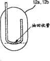
图2示出了收集器中的油回收管结构。Figure 2 shows the structure of the oil recovery pipe in the collector.
如图2所示,无法回收积存在油回收管底部的油,由此油保持积存在底部。As shown in FIG. 2, the oil accumulated at the bottom of the oil recovery pipe cannot be recovered, and thus the oil remains accumulated at the bottom.
由于上述原因,油循环的量将短少,且系统的可靠性下降。For the above reasons, the amount of oil circulation will be short, and the reliability of the system will be lowered.
图3为现有技术室外单元压缩机周围的管线结构的示意图。Fig. 3 is a schematic diagram of the pipeline structure around the compressor of the outdoor unit in the prior art.
连接于压缩机150的管152、153经过覆盖处理(roofing treatment),并对其应用独立的减震块(focusing mass)140。即低温、低压制冷剂蒸汽从室内单元(未示出)通过连接至辅助阀110的外管流入室外单元中,而此低温、低压制冷剂蒸汽的液体在其通过收集器130时被去除,低温、低压制冷剂蒸汽通过压缩机150压缩并在流入冷凝器前变为高温、高压制冷剂蒸汽。The
在压缩机150中的压缩过程期间经常发生剧烈震动,因此必须控制此震动通过连接至压缩机150的吸入和排出管152、153传递到系统的其它部分。为了控制震动的传递,可以在覆盖(roofing)处理后延长管子。另外,可以在覆盖管的下部,更具体而言,在压缩机150的吸入和排出管152、153覆盖处的下端,设置由诸如橡胶的弹性材料制成的减震块140。Vigorous vibrations often occur during the compression process in the
当连接至压缩机150和收集器130的管子中通过反向圈120时,震动也被抑制。此处,反向圈120设置在系统的上后部,未干扰管线,并且反向圈120的入口和出口都面向下。Vibration is also damped when the
另外,对吸入管152进行覆盖处理时,从收集器130至反向方向U形弯曲管子,并随后从反向圈119的位置向上L形弯曲,并径直继续。对于排出管153的覆盖,所述管排出单元向反方向U形弯曲,然后沿着底表面再一次U形弯曲,随后从反向圈119的位置L形弯曲,最后径直向上。In addition, when covering the
另外,考虑与外侧管的连接,用于载运在压缩机150中流动的制冷剂蒸汽的制冷剂蒸汽管151未经过覆盖处理,而是直接连接至反向圈120和辅助阀110。In addition, the
发明内容Contents of the invention
本发明的目的在于至少解决上述问题和/或缺点,并在于至少提供下述优点。The present invention aims to solve at least the above-mentioned problems and/or disadvantages and to provide at least the advantages described below.
因此,本发明的一个目的在于通过提供一种用于通过改变制冷剂流向收集器的线路以确保液体制冷剂存在于确定的管路之间,从而在室外单元处于待机模式而电源打开且压缩机关闭的情况下防止液体制冷剂积存的方法来解决前述的问题。Therefore, it is an object of the present invention to provide a method for ensuring that liquid refrigerant exists between certain lines by changing the line of refrigerant flow to the collector, so that when the outdoor unit is in standby mode and the power is turned on and the compressor The aforementioned problem is solved by preventing liquid refrigerant from accumulating in case of shutdown.
本发明的另一目的在于提供一种用于防止空调的液体制冷剂积存的设备,从而在收集器的底部回收制冷剂。Another object of the present invention is to provide a device for preventing the accumulation of liquid refrigerant of an air conditioner, thereby recovering the refrigerant at the bottom of the collector.
本发明的上述和其它目的及优点通过提供一种用于防止空调的液体制冷剂积存的方法来实现,其中该方法包括步骤:确定压缩机的状态;若压缩机处于待机模式或关闭状态的至少一种,打开四通阀;确定是否压缩机的状态处于待机模式或关闭状态持续超过预定的时间;以及若压缩机持续该状态超过预定时间,关闭膨胀阀,其中高压制冷剂流入关闭的膨胀阀,低压制冷剂通过四通阀流入止回阀。The above and other objects and advantages of the present invention are achieved by providing a method for preventing the accumulation of liquid refrigerant in an air conditioner, wherein the method comprises the steps of: determining the state of the compressor; One, opening the four-way valve; determining whether the state of the compressor is in standby mode or off for more than a predetermined time; and closing the expansion valve if the state of the compressor continues for more than a predetermined time, wherein high-pressure refrigerant flows into the closed expansion valve , the low-pressure refrigerant flows into the check valve through the four-way valve.
在本发明的典型实施例中,若向压缩机输入启动信号,根据制冷/加热模式控制四通阀,并且打开关闭的膨胀阀。In an exemplary embodiment of the present invention, if an activation signal is input to the compressor, the four-way valve is controlled according to the cooling/heating mode, and the closed expansion valve is opened.
本发明的另一方面提供一种用于防止空调的液体制冷剂积存的设备,其中该设备包括:连接至压缩机从而喷射收集器的油的吸入管;一端与吸入管连接而另一端与收集器连接的液体回收管;以及用于控制液体回收管的打开/关闭的液体回收阀。Another aspect of the present invention provides an apparatus for preventing liquid refrigerant accumulation of an air conditioner, wherein the apparatus includes: a suction pipe connected to a compressor so as to spray the oil of the collector; one end is connected to the suction pipe and the other end is connected to the collector A liquid recovery pipe connected to the controller; and a liquid recovery valve for controlling the opening/closing of the liquid recovery pipe.
在本发明的典型实施例中,液体回收管的该另一端与收集器的下端连接,从而将收集器底部的油转移至吸入管。In an exemplary embodiment of the invention, this other end of the liquid recovery pipe is connected to the lower end of the collector, thereby diverting the oil at the bottom of the collector to the suction pipe.
本发明的又一方面提供了一种用于防止空调的液体制冷剂积存的方法,该方法包括步骤:在制冷或加热模式下操作空调的压缩机;以及打开液体回收阀,用于控制与压缩机和收集器连接的液体回收管,并减少油。Yet another aspect of the present invention provides a method for preventing the accumulation of liquid refrigerant in an air conditioner, the method comprising the steps of: operating a compressor of the air conditioner in cooling or heating mode; and opening a liquid recovery valve for controlling and compressing The liquid recovery pipe connected to the machine and the collector, and reduces the oil.
在本发明的典型实施例中,若空调处于加热模式,则该方法包括步骤:确定压缩机的排出温度是否高于预定温度;若压缩机的排出温度高于预定温度,则打开设置在收集器下端的液体回收阀;以及打开液体回收阀后,向压缩机喷出低压液体制冷剂,以降低压缩机的排出温度。In an exemplary embodiment of the present invention, if the air conditioner is in the heating mode, the method includes the steps of: determining whether the discharge temperature of the compressor is higher than a predetermined temperature; if the discharge temperature of the compressor is higher than the predetermined temperature, opening the The liquid recovery valve at the lower end; and after opening the liquid recovery valve, spray low-pressure liquid refrigerant to the compressor to reduce the discharge temperature of the compressor.
在本发明的典型实施例中,若空调处于制冷模式,周期性地打开液体回收阀,从而回收收集器底部的油。In an exemplary embodiment of the present invention, if the air conditioner is in cooling mode, the liquid recovery valve is periodically opened to recover the oil at the bottom of the collector.
根据本发明,流入收集器的制冷剂被阻挡,并且取而代之的,制冷剂处于制冷剂管中。由此,使得制冷剂无法流入压缩机中,且改善了压缩机的稳定性。According to the invention, the refrigerant flowing into the collector is blocked and instead the refrigerant is in the refrigerant pipe. Thus, the refrigerant cannot flow into the compressor, and the stability of the compressor is improved.
另外,在液体制冷剂积存在收集器中的情况下,收集器下端的液体制冷剂周期性地回收,或基于压缩机的排出温度回收,使得系统无需经受缺油的问题。In addition, in the case where liquid refrigerant is accumulated in the accumulator, the liquid refrigerant at the lower end of the accumulator is recovered periodically, or based on the discharge temperature of the compressor, so that the system does not need to suffer from oil shortage.
本发明的其它优点、目的和特点将部分地通过下面的描述而展示出来,部分地通过验证下述内容为本领域技术人员所明晰或通过实践本发明而被掌握。本发明的目的和优点可如所附权利要求中具体指出的来实现和获得。Other advantages, objects and features of the present invention will be demonstrated partly through the following description, and partly will be apparent to those skilled in the art by verifying the following contents or mastered by practicing the present invention. The objects and advantages of the invention may be realized and attained as particularly pointed out in the appended claims.
附图说明Description of drawings
下面,将参照以下附图详细介绍本发明,附图中相同的附图标记表示相同的元件,其中:In the following, the present invention will be described in detail with reference to the following drawings, in which like reference numerals represent like elements, wherein:
图1为示出现有技术液体制冷剂积存的示意图;FIG. 1 is a schematic diagram showing the accumulation of liquid refrigerant in the prior art;
图2示出收集器中的油回收结构;Fig. 2 shows the oil recovery structure in the collector;
图3为示出现有技术室外单元压缩机周围的管线结构的示意图;Fig. 3 is a schematic diagram showing the pipeline structure around the compressor of the outdoor unit in the prior art;
图4为根据本发明用于防止液体制冷剂积存的空调设备的示意图;4 is a schematic diagram of an air conditioner for preventing liquid refrigerant from accumulating according to the present invention;
图5为说明根据本发明防止液体制冷剂积存的流程图;Fig. 5 is a flowchart illustrating the prevention of liquid refrigerant accumulation according to the present invention;
图6和7为示出根据本发明用于防止液体制冷剂积存的设备的示意图;以及6 and 7 are schematic diagrams showing an apparatus for preventing liquid refrigerant from accumulating according to the present invention; and
图8为说明通过采用图6和7的设备防止液体制冷剂积存的方法的流程图。FIG. 8 is a flowchart illustrating a method of preventing liquid refrigerant pooling by employing the apparatus of FIGS. 6 and 7. FIG.
具体实施方式Detailed ways
下面,将参照附图根据本发明优选实施例详细说明用于防止空调液体制冷剂积存的设备及其方法。Hereinafter, an apparatus for preventing liquid refrigerant accumulation of an air conditioner and a method thereof according to preferred embodiments of the present invention will be described in detail with reference to the accompanying drawings.
图4为根据本发明用于防止液体制冷剂积存的空调设备的示意图,而图5为说明根据本发明防止液体制冷剂积存的方法的流程图。4 is a schematic diagram of an air conditioner for preventing liquid refrigerant accumulation according to the present invention, and FIG. 5 is a flowchart illustrating a method of preventing liquid refrigerant accumulation according to the present invention.
参照图4,该空调为空气调节或加热、空气调节/加热的组合多体空调设备,并包括至少一个室内单元120、至少一个室外单元100,该室内单元和室外单元通过长/中/短长度的管连接。Referring to Fig. 4, the air conditioner is an air conditioning or heating, air conditioning/heating combination multi-body air conditioning equipment, and includes at least one
当空调处于制冷模式时,压缩机102a、102b压缩制冷剂,压缩的制冷剂通过油分离器104a、104b、止回阀105a、105b、以及四通阀106供给室外热交换器108。When the air conditioner is in cooling mode,
在室外热交换器108中,制冷剂与室外空气进行热交换,并改变为室温制冷剂。随后,制冷剂通过室外EEV 110并变为低温、低压制冷剂,并通过室外辅助阀116a转移至室内单元的室内EEV 121和室内热交换器122。因此,通过与室内空气的热交换进行制冷操作。In the
通过室内热交换器122进行了热交换的制冷剂变为低温、低压制冷剂,并经室外单元100的四通阀106积存在收集器112a、112b中。The refrigerant that has undergone heat exchange through the
连接至变频压缩机102a和定速压缩机102b的收集器112a、112b将油液从制冷剂蒸汽中分离出来,并仅将制冷剂蒸汽喷入压缩机102a、102b。The
另一方面,在加热模式中,空调以制冷模式驱动循环相反的方式运行。首先,压缩机102a、102b将制冷剂压缩为高温、高压状态,而压缩的制冷剂通过油分离器104a、104b和止回阀105a、105b、以及连接至四通阀106的流动线路,并通过室内辅助阀116b转移至室内单元120的室内热交换器122。在室内热交换器122中,制冷剂与室内空气进行热交换,并通过室内EEV 121减压、膨胀,随后通过辅助阀116a流入室外单元100。随后,此制冷剂通过室外EEV 110和室外热交换器108变为低温、低压状态。In heating mode, on the other hand, the air conditioner operates in the opposite way that cooling mode drives the cycle. First, the
图4中的箭头表示当室外单元处于待机模式或关闭时,制冷剂的流动路线。另外,图中的实线示出了基于根据本发明实施例的算法,制冷剂流入室外EEV 110和止回阀105a、105b前的状态。Arrows in FIG. 4 indicate refrigerant flow routes when the outdoor unit is in standby mode or turned off. In addition, the solid line in the figure shows the state before the refrigerant flows into the
同时,通过室外热交换器108经过热交换的制冷剂经四通阀106流入收集器112a、112b,液体制冷剂积存在收集器112a、112b中,而制冷剂蒸汽再次通过吸入管115喷入压缩机。At the same time, the refrigerant that has undergone heat exchange through the
下面,将参照图5说明本发明。Next, the present invention will be described with reference to FIG. 5 .
当多体空调的室外单元处于待机模式,而空调处于启动状态时,压缩机102a、102b处于待机模式或关闭(S101、S103)。When the outdoor unit of the multi-body air conditioner is in the standby mode and the air conditioner is in the start state, the
当压缩机102a、102b关闭(Poff)或处于待机模式时,四通阀106打开(S105)。When the
确定压缩机的状态(关闭或待机)是否持续特定的时间段(Tref)(S107),若是,关闭室外EEV 110。Determine whether the state of the compressor (off or standby) lasts for a specific period of time (Tref) (S107), if so, turn off the
随着四通阀106打开,止回阀105a、105b和设置在压缩机102a、102b排出侧的低压管彼此连接。换言之,四通阀106改变至加热模式线路,并连通室内辅助阀116b和通过连接管连接至室内热交换器122并连接至止回阀105a、105b的四通阀106。另外,在关闭室外EEV 110时,室内热交换器122和室外EEV 110连通。With the four-
因此,当压缩机102a、102b关闭时,室内一侧管线内的制冷剂用于通过室内辅助阀116b填满四通阀106和止回阀105a、105b。另外,高压管中的制冷剂经室外辅助阀116a和接收器118流入室外EEV 110(S11)。Therefore, when the
利用上述方法,尽管制冷剂可泄漏出止回阀105a、105b,压缩机下部处的收集器112a、112b的油部分为空,使得在工作开始时液体制冷剂无法流入。With the method described above, although refrigerant can leak out of the
在上述过程的中间或在执行上述过程之后,确定是否输入压缩机启动信号(S113),若是,打开辅助阀116a、116b,并开启四通阀106和室外EEV110(S115)。In the middle of the above process or after performing the above process, it is determined whether a compressor start signal is input (S113), and if so, the
若对于指定的时间段,压缩机关闭或处于待机模式,则关闭室内/外辅助阀116b、116a,或可打开或关闭特定的阀门以防止制冷剂进入室内单元。If the compressor is off or in standby mode for a specified period of time, the indoor/outdoor
图6示出能够回收收集器112a、112b中的积存制冷剂的设备。FIG. 6 shows a device capable of recovering the accumulated refrigerant in the
如图6所示,制冷剂回收设备包括与压缩机102a、102b和收集器112a、112b连接的吸入管115;一端与吸入管115连接而另一端与收集器112a、112b下端连接的液体回收管117a、117b;以及分别安装在液体回收管117a、117b处、根据是否需要回收液体而打开或关闭的液体回收阀118a、118b。As shown in Figure 6, the refrigerant recovery equipment includes a
在有多个收集器112a、112b的情况下,液体回收管117a、117b分别连接至与收集器112a、112b的下端连接的压力调节管119。In the case where there are a plurality of
液体回收阀118a、118b优选为电磁阀或止回阀。The
由于压缩机102a、102b和收集器112a、112b在制冷模式下主要由油填充,因此液体回收阀118a、118b周期性地开启,从而将油转移至与收集器112a、112b的下端连接的压力调节管119。随后,油通过液体回收管117a、117b转移至吸入管115。Since the
转移至吸入管115后,油被回收至压缩机102a、102b。After being transferred to the
作为一种实施例,给定压缩机102a、102b在工作中,而液体回收阀118a、118b可以首先关闭或打开从而收集液体制冷剂。As an example, given that the
另外,由于大量油积存在收集器112a、112b的底部,为回收更多的油,必须增加系统内的油循环,其进而保护压缩机并减少了总填油量。In addition, since a large amount of oil accumulates at the bottom of the
另一方面,在加热模式中,由于室外温度低,压缩机102a、102b为加热而在高频下工作,由此提高排出的温度。通常,当压缩机102a、102b的排出温度提高时,压缩机的吸入管115打开,而高压制冷剂喷入压缩机102a、102b中,从而降低压缩机的温度。On the other hand, in the heating mode, since the outdoor temperature is low, the
然而,在低温区域中,经常发现压缩机的排出温度提高。由此,更加经常地发生液体制冷剂回收,且驱动循环变得不稳定,由此降低了加热能力。为此,当压缩机102a、102b的排出温度提高至高于指定温度范围时,打开连接至收集器112a、112b下端的液体回收阀118a、118b,并在压缩机102a、102b上通过液体回收管117a、117b和吸入管115喷射低压液体制冷剂,由此降低压缩机的排出温度。However, in low temperature regions, it is often found that the discharge temperature of the compressor increases. As a result, liquid refrigerant recovery occurs more often, and the drive cycle becomes unstable, thereby reducing the heating capacity. For this purpose, when the discharge temperature of the
通过应用液体回收管117a、117b,现在可以收集油回收管底部的积存油,而其由于现有技术收集器中的油回收管的结构而被视作是不可能。另外,还可以在比通常要高的位置设置油回收管。By applying the
由于回收了收集器112a、112b底部积存的油,系统的油循环增加,并且确保了压缩机的可靠性。即使在压缩机的排出温度较高时,可以仅简单地通过为压缩机提供液体制冷剂来降低压缩机的排出温度而不影响循环。Since the oil accumulated at the bottom of the
在上述实施例中,应注意液体回收阀的数量与具有不同功能的压缩机(变频/定速压缩机)的数量相对应。In the above embodiments, it should be noted that the number of liquid recovery valves corresponds to the number of compressors (variable frequency/fixed speed compressors) with different functions.
图7示出了图6的液体回收管117a或117b和液体回收阀118a或118b的另一种实施例,但其操作实际相同。FIG. 7 shows another embodiment of the
图8说明通过采用图6的系统防止液体制冷剂积存的方法。首先,确定系统是否处于加热模式(S121)。若是,检测压缩机的排出温度和室外温度(S123)。若压缩机的排出温度高于指定温度(S125),收集器下端的液体回收阀打开,且向压缩机喷射低压液体制冷剂(S127),从而降低压缩机的排出温度(S129)。FIG. 8 illustrates a method of preventing liquid refrigerant pooling by employing the system of FIG. 6 . First, it is determined whether the system is in a heating mode (S121). If yes, the discharge temperature of the compressor and the outdoor temperature are detected (S123). If the discharge temperature of the compressor is higher than the specified temperature (S125), the liquid recovery valve at the lower end of the collector is opened, and low-pressure liquid refrigerant is injected into the compressor (S127), thereby reducing the discharge temperature of the compressor (S129).
对于制冷模式,而非加热模式(S131),收集器下端的液体回收阀周期性地打开,并且将油回收至压缩机(S133、S135),由此降低压缩机的排出温度(S129)。For cooling mode, not heating mode (S131), the liquid recovery valve at the lower end of the collector is periodically opened, and oil is recovered to the compressor (S133, S135), thereby reducing the discharge temperature of the compressor (S129).
因此,根据本发明,当空调不正常工作时,制冷剂至收集器的流通线路改变,使得制冷剂无法流入压缩机,而可以回收收集器下端的制冷剂。Therefore, according to the present invention, when the air conditioner does not work normally, the circulation line from the refrigerant to the collector is changed, so that the refrigerant cannot flow into the compressor, and the refrigerant at the lower end of the collector can be recovered.
虽然,已参照特定的优选实施例示出并介绍了本发明,本领域技术人员将理解,可以在不脱离由所附权利要求所限定的本发明的实质和范围的基础上对其形式和细节作各种改变。Although the invention has been shown and described with reference to certain preferred embodiments, it will be understood by those skilled in the art that changes may be made in form and detail without departing from the spirit and scope of the invention as defined by the appended claims. Various changes.
上述实施例和优点仅为示意性,而不对本发明构成限制。本发明所教导的内容易于应用于各种类型的设备。对本发明的描述是出于说明,而非限制所应保护的范围。对本领域技术人员而言,多种替换、调整和变化是显而易见的。权利要求中,手段加功能的句段是为覆盖在此介绍的结构以及执行所叙述的功能,并且不仅是结构上的等效物,还包括等效的结构。The above-mentioned embodiments and advantages are only illustrative and do not limit the present invention. The teachings of the present invention are readily applicable to various types of devices. The description of the present invention is for illustration, not for limiting the scope of protection. Numerous alternatives, adaptations and changes will be apparent to those skilled in the art. In the claims, means-plus-function clauses are intended to cover the structures presented herein as well as perform the recited function and not only structural equivalents but also equivalent structures.
Claims (11)
Applications Claiming Priority (3)
| Application Number | Priority Date | Filing Date | Title |
|---|---|---|---|
| KR1020030072993AKR100564444B1 (en) | 2003-10-20 | 2003-10-20 | Apparatus and method for preventing accumulation of liquid refrigerant in air conditioners |
| KR72993/2003 | 2003-10-20 | ||
| KR72993/03 | 2003-10-20 |
Publications (2)
| Publication Number | Publication Date |
|---|---|
| CN1609536A CN1609536A (en) | 2005-04-27 |
| CN100441982Ctrue CN100441982C (en) | 2008-12-10 |
Family
ID=34386783
Family Applications (1)
| Application Number | Title | Priority Date | Filing Date |
|---|---|---|---|
| CNB2004100749100AExpired - Fee RelatedCN100441982C (en) | 2003-10-20 | 2004-08-30 | Device and method for preventing accumulation of liquid refrigerant in air conditioner |
Country Status (6)
| Country | Link |
|---|---|
| US (1) | US7584624B2 (en) |
| EP (2) | EP1526340B1 (en) |
| JP (2) | JP4008913B2 (en) |
| KR (1) | KR100564444B1 (en) |
| CN (1) | CN100441982C (en) |
| DE (2) | DE602004009383T2 (en) |
Families Citing this family (20)
| Publication number | Priority date | Publication date | Assignee | Title |
|---|---|---|---|---|
| KR100688166B1 (en)* | 2004-12-10 | 2007-03-02 | 엘지전자 주식회사 | Air conditioner |
| KR100671301B1 (en)* | 2004-12-22 | 2007-01-19 | 삼성전자주식회사 | Air conditioner |
| KR101172445B1 (en)* | 2005-02-15 | 2012-08-07 | 엘지전자 주식회사 | Multi-air conditioner capable of cooling and heating simultaneously |
| US7415838B2 (en) | 2005-02-26 | 2008-08-26 | Lg Electronics Inc | Second-refrigerant pump driving type air conditioner |
| KR100712857B1 (en) | 2005-08-24 | 2007-05-02 | 엘지전자 주식회사 | Refrigerant amount control method of mixed unitary air conditioner |
| JP4726600B2 (en)* | 2005-10-06 | 2011-07-20 | 三菱電機株式会社 | Refrigeration air conditioner |
| JP4640142B2 (en)* | 2005-11-30 | 2011-03-02 | ダイキン工業株式会社 | Refrigeration equipment |
| KR20080020771A (en)* | 2006-09-01 | 2008-03-06 | 엘지전자 주식회사 | Water Cooled Air Conditioners |
| JP4902585B2 (en)* | 2008-04-04 | 2012-03-21 | 三菱電機株式会社 | Air conditioner |
| JP5229476B2 (en)* | 2008-12-11 | 2013-07-03 | 株式会社富士通ゼネラル | Refrigeration apparatus and control method thereof |
| JP2010139155A (en)* | 2008-12-11 | 2010-06-24 | Fujitsu General Ltd | Refrigeration apparatus |
| WO2010113395A1 (en)* | 2009-03-31 | 2010-10-07 | 三菱電機株式会社 | Refrigeration device |
| CN102803864B (en)* | 2009-06-29 | 2015-07-22 | 江森自控科技公司 | System for limiting pressure differences in dual compressor chillers |
| JP6087713B2 (en)* | 2013-04-24 | 2017-03-01 | 株式会社神戸製鋼所 | Compression device |
| CN109564031A (en)* | 2016-08-04 | 2019-04-02 | 三菱电机株式会社 | Refrigerating plant |
| ES2997862T3 (en)* | 2018-12-28 | 2025-02-18 | Thermo King Llc | Methods and systems for supplemental flow control of working fluid through a climate control circuit |
| CN113701873B (en)* | 2020-05-19 | 2024-11-01 | 广州汽车集团股份有限公司 | Refrigerant flow sound detection device, system and method |
| EP4286773A1 (en)* | 2022-06-01 | 2023-12-06 | Carrier Corporation | Transportation refrigeration unit and method of measuring quantity of refrigerant in the same |
| DE102022118621A1 (en) | 2022-07-26 | 2024-02-01 | Audi Aktiengesellschaft | Refrigeration system for supercritical refrigerant with additional refrigerant storage for a motor vehicle, motor vehicle with such a refrigeration system |
| JP7398582B1 (en) | 2023-02-16 | 2023-12-14 | 東芝キヤリア株式会社 | air conditioner |
Citations (6)
| Publication number | Priority date | Publication date | Assignee | Title |
|---|---|---|---|---|
| US4693089A (en)* | 1986-03-27 | 1987-09-15 | Phenix Heat Pump Systems, Inc. | Three function heat pump system |
| JPH0875274A (en)* | 1994-09-05 | 1996-03-19 | Sanyo Electric Co Ltd | Refrigerating equipment |
| WO1999002928A1 (en)* | 1997-07-11 | 1999-01-21 | Zexel Corporation | Freezer |
| CN1227906A (en)* | 1998-01-22 | 1999-09-08 | 东芝株式会社 | air conditioner |
| JPH11278045A (en)* | 1997-09-24 | 1999-10-12 | Denso Corp | Refrigerating cycle device |
| CN1386184A (en)* | 2000-07-13 | 2002-12-18 | 大金工业株式会社 | Refrigerant circuit of air conditioner |
Family Cites Families (16)
| Publication number | Priority date | Publication date | Assignee | Title |
|---|---|---|---|---|
| US2276814A (en)* | 1938-07-30 | 1942-03-17 | Allin B Crouch | Refrigeration system |
| US3110164A (en)* | 1961-09-28 | 1963-11-12 | Hupp Corp | Heat pumps |
| US4576555A (en)* | 1984-11-13 | 1986-03-18 | Tecumseh Products Company | Oil dispersing device |
| JPS61143659A (en)* | 1984-12-18 | 1986-07-01 | 三菱電機株式会社 | Refrigeration cycle device |
| US5025634A (en)* | 1989-04-25 | 1991-06-25 | Dressler William E | Heating and cooling apparatus |
| JPH04208368A (en)* | 1990-11-30 | 1992-07-30 | Toshiba Corp | Air conditioner |
| JP2826693B2 (en)* | 1993-05-17 | 1998-11-18 | デンゲン株式会社 | Refrigerant gas recovery device for single-port valve recovery container |
| JP2970358B2 (en)* | 1993-10-18 | 1999-11-02 | ダイキン工業株式会社 | Air conditioner |
| PT672875E (en) | 1994-03-15 | 2000-11-30 | Mitsubishi Electric Corp | AIR CONDITIONING SYSTEM, ACCUMULATOR FOR THE SAME AND PROCESS FOR THE ACCUMULATING MANUFACTURING |
| DE69817943T2 (en)* | 1997-07-31 | 2004-07-15 | Denso Corp., Kariya | Device with a cooling circuit |
| KR19990079082A (en)* | 1998-04-01 | 1999-11-05 | 윤종용 | Refrigerant Cycle of Air Conditioner |
| JP2001133056A (en)* | 1999-11-04 | 2001-05-18 | Mitsubishi Electric Corp | Air conditioner |
| US6276148B1 (en)* | 2000-02-16 | 2001-08-21 | David N. Shaw | Boosted air source heat pump |
| US6484517B2 (en)* | 2001-02-27 | 2002-11-26 | Mikhail Levitin | Compressor oil pressure control method and unit |
| KR100484914B1 (en)* | 2002-03-19 | 2005-04-22 | 위니아만도 주식회사 | Method for collecting freezing material of aircondition |
| KR100484799B1 (en)* | 2002-06-19 | 2005-04-22 | 엘지전자 주식회사 | Compressor's Operating Method of Air Conditioner With Two Compressors |
- 2003
- 2003-10-20KRKR1020030072993Apatent/KR100564444B1/ennot_activeExpired - Fee Related
- 2004
- 2004-08-30CNCNB2004100749100Apatent/CN100441982C/ennot_activeExpired - Fee Related
- 2004-08-31USUS10/929,457patent/US7584624B2/enactiveActive
- 2004-10-12JPJP2004297902Apatent/JP4008913B2/ennot_activeExpired - Fee Related
- 2004-10-19DEDE602004009383Tpatent/DE602004009383T2/ennot_activeExpired - Lifetime
- 2004-10-19DEDE602004021442Tpatent/DE602004021442D1/ennot_activeExpired - Lifetime
- 2004-10-19EPEP04077877Apatent/EP1526340B1/ennot_activeExpired - Lifetime
- 2004-10-19EPEP06120395Apatent/EP1760410B1/ennot_activeExpired - Lifetime
- 2007
- 2007-07-04JPJP2007176678Apatent/JP4394709B2/ennot_activeExpired - Fee Related
Patent Citations (6)
| Publication number | Priority date | Publication date | Assignee | Title |
|---|---|---|---|---|
| US4693089A (en)* | 1986-03-27 | 1987-09-15 | Phenix Heat Pump Systems, Inc. | Three function heat pump system |
| JPH0875274A (en)* | 1994-09-05 | 1996-03-19 | Sanyo Electric Co Ltd | Refrigerating equipment |
| WO1999002928A1 (en)* | 1997-07-11 | 1999-01-21 | Zexel Corporation | Freezer |
| JPH11278045A (en)* | 1997-09-24 | 1999-10-12 | Denso Corp | Refrigerating cycle device |
| CN1227906A (en)* | 1998-01-22 | 1999-09-08 | 东芝株式会社 | air conditioner |
| CN1386184A (en)* | 2000-07-13 | 2002-12-18 | 大金工业株式会社 | Refrigerant circuit of air conditioner |
Also Published As
| Publication number | Publication date |
|---|---|
| CN1609536A (en) | 2005-04-27 |
| US20050081537A1 (en) | 2005-04-21 |
| EP1760410A1 (en) | 2007-03-07 |
| US7584624B2 (en) | 2009-09-08 |
| KR20050037731A (en) | 2005-04-25 |
| JP2005127703A (en) | 2005-05-19 |
| DE602004009383T2 (en) | 2008-07-10 |
| KR100564444B1 (en) | 2006-03-29 |
| JP2007285699A (en) | 2007-11-01 |
| JP4394709B2 (en) | 2010-01-06 |
| JP4008913B2 (en) | 2007-11-14 |
| EP1526340B1 (en) | 2007-10-10 |
| DE602004021442D1 (en) | 2009-07-16 |
| EP1760410B1 (en) | 2009-06-03 |
| DE602004009383D1 (en) | 2007-11-22 |
| EP1526340A1 (en) | 2005-04-27 |
Similar Documents
| Publication | Publication Date | Title |
|---|---|---|
| CN100441982C (en) | Device and method for preventing accumulation of liquid refrigerant in air conditioner | |
| CN101749890B (en) | Refrigeration device and control method thereof | |
| US8505321B2 (en) | Refrigeration apparatus with reduced constraints on placement of utilization unit relative to heat source unit | |
| JP5484930B2 (en) | Air conditioner | |
| JP4323484B2 (en) | Refrigeration cycle equipment | |
| CN100356116C (en) | Air conditioner | |
| WO2017061009A1 (en) | Refrigeration cycle device | |
| JP4898610B2 (en) | Valve opening pulse setting method for electric expansion valve and multi-type air conditioner | |
| JP2011047545A (en) | Operation control method of multi-chamber type air conditioner | |
| JP4582261B1 (en) | Air conditioning unit for heating | |
| CN100443833C (en) | freezer | |
| JP3750520B2 (en) | Refrigeration equipment | |
| AU2007225990B2 (en) | Method for the recovery of refrigeration oil | |
| JP2007046896A (en) | Operation control device and method for air conditioner provided with a plurality of compressors | |
| JP4082040B2 (en) | Refrigeration equipment | |
| JP2011242097A (en) | Refrigerating apparatus | |
| KR20220040221A (en) | Multi-air conditioner for heating and cooling operations | |
| JPH04320763A (en) | Freezer | |
| JP4453195B2 (en) | Refrigeration equipment | |
| KR100758955B1 (en) | Compressor Fuel Oil Method and Apparatus of Air Conditioner | |
| JP2019002586A (en) | Heat pump system | |
| KR20070066589A (en) | Compressor Operation Method of Multi-type Air Conditioner | |
| JP2003232571A (en) | Refrigeration equipment |
Legal Events
| Date | Code | Title | Description |
|---|---|---|---|
| C06 | Publication | ||
| PB01 | Publication | ||
| C10 | Entry into substantive examination | ||
| SE01 | Entry into force of request for substantive examination | ||
| C14 | Grant of patent or utility model | ||
| GR01 | Patent grant | ||
| CF01 | Termination of patent right due to non-payment of annual fee | ||
| CF01 | Termination of patent right due to non-payment of annual fee | Granted publication date:20081210 Termination date:20190830 |