CN100438468C - Vehicle inspection management system and method - Google Patents
Vehicle inspection management system and methodDownload PDFInfo
- Publication number
- CN100438468C CN100438468CCNB2005100637129ACN200510063712ACN100438468CCN 100438468 CCN100438468 CCN 100438468CCN B2005100637129 ACNB2005100637129 ACN B2005100637129ACN 200510063712 ACN200510063712 ACN 200510063712ACN 100438468 CCN100438468 CCN 100438468C
- Authority
- CN
- China
- Prior art keywords
- screen
- detection
- time
- standard
- described detection
- Prior art date
- Legal status (The legal status is an assumption and is not a legal conclusion. Google has not performed a legal analysis and makes no representation as to the accuracy of the status listed.)
- Expired - Fee Related
Links
Images


Classifications
- G—PHYSICS
- G06—COMPUTING OR CALCULATING; COUNTING
- G06Q—INFORMATION AND COMMUNICATION TECHNOLOGY [ICT] SPECIALLY ADAPTED FOR ADMINISTRATIVE, COMMERCIAL, FINANCIAL, MANAGERIAL OR SUPERVISORY PURPOSES; SYSTEMS OR METHODS SPECIALLY ADAPTED FOR ADMINISTRATIVE, COMMERCIAL, FINANCIAL, MANAGERIAL OR SUPERVISORY PURPOSES, NOT OTHERWISE PROVIDED FOR
- G06Q10/00—Administration; Management
- G06Q10/06—Resources, workflows, human or project management; Enterprise or organisation planning; Enterprise or organisation modelling
Landscapes
- Engineering & Computer Science (AREA)
- Business, Economics & Management (AREA)
- Human Resources & Organizations (AREA)
- Strategic Management (AREA)
- Economics (AREA)
- Entrepreneurship & Innovation (AREA)
- Educational Administration (AREA)
- Game Theory and Decision Science (AREA)
- Development Economics (AREA)
- Marketing (AREA)
- Operations Research (AREA)
- Quality & Reliability (AREA)
- Tourism & Hospitality (AREA)
- Physics & Mathematics (AREA)
- General Business, Economics & Management (AREA)
- General Physics & Mathematics (AREA)
- Theoretical Computer Science (AREA)
- General Factory Administration (AREA)
- Automobile Manufacture Line, Endless Track Vehicle, Trailer (AREA)
Abstract
Description
Translated fromChinese技术领域technical field
本发明涉及车辆生产线上车辆的检测管理系统和方法。The invention relates to a detection management system and method for vehicles on a vehicle production line.
背景技术Background technique
迄今,已知一个系统中有大量的用于车辆生产线上制成车辆的检测过程,并且在各检测过程中检测数据从主计算机下载到个人电脑,检测工人(本文以后缩写为“检测工人”)根据检测数据进行检测,检测的结果被输入个人电脑并传输到主计算机。Hitherto, it has been known that a system has a large number of inspection processes for vehicles produced on a vehicle production line, and inspection data is downloaded from a host computer to a personal computer in each inspection process, and inspection workers (hereafter abbreviated as "inspection workers") Inspection is performed based on the inspection data, and the inspection results are entered into the personal computer and transmitted to the main computer.
另外,也已知这样一个系统,其中,在检测开始时,一张检测指令单被贴在完成的车辆上,检测指令单上用条形码印有在各检测过程中执行的检测所必须的参考数据,在第一个过程中参考数据通过读取相应的条形码来获得,根据参考数据执行检测,检测结果通过条形码标签的形式贴在检测指令单上发出并传输到下一个过程(日本发明申请公报号NO2002-12177)In addition, a system is also known in which, at the start of the inspection, an inspection order sheet is affixed to the completed vehicle, and the inspection order sheet is printed with a barcode with reference data necessary for the inspection performed in each inspection process , in the first process, the reference data is obtained by reading the corresponding bar code, and the detection is performed according to the reference data, and the detection result is sent out on the detection instruction sheet in the form of a bar code label and transmitted to the next process (Japanese Invention Application Publication No. NO2002-12177)
顺便提及,为每一个过程中执行的检测工作设置必须的标准操作时间以及让负责检测的工人(以下简称“检测工人”)保持对于装配各种零件的工作都不同的时间是有困难的。因此,检测工作所用时间是否增加或是减少极大地取决于检测工人。比如,当一条生产线上的一项装配工作因为延误而紧张进行时,用于检测的时间会大大缩短,这将导致检测工作执行不充分的可能性。Incidentally, it is difficult to set a necessary standard operating time for inspection work performed in each process and to keep a worker in charge of inspection (hereinafter referred to as "inspection worker") at a different time for work of assembling various parts. Therefore, whether the time spent on inspection work increases or decreases greatly depends on the inspection workers. For example, when an assembly job on a production line is strained due to delays, the time spent on inspection is greatly reduced, which leads to the possibility of insufficient inspection work being performed.
本发明的一个目的是提供一种车辆检测管理系统和方法,该系统和方法能够通过测量每一过程中检测工作所用时间以及将该时间与标准操作时间作比较,在检测必须的操作时间长于或者短于标准操作时间时向检测工人发出警告。An object of the present invention is to provide a vehicle inspection management system and method, which can detect when the operation time necessary for the inspection is longer than or Warn inspectors when standard operating time is less than expected.
本发明的另一个目的是提供一种可以通过检测终端通知检测工人检测所必须的标准时间的车辆检测管理系统。Another object of the present invention is to provide a vehicle inspection management system that can notify inspection workers of the necessary standard time for inspection through the inspection terminal.
本发明的进一步目的是提供一种可以处理向每一个检测工人发出的警告次数的车辆检测管理系统。A further object of the present invention is to provide a vehicle inspection management system that can handle the number of warnings issued to each inspection worker.
发明内容Contents of the invention
根据本发明的一个方面提供一种车辆检测管理系统,包括:According to one aspect of the present invention, a vehicle detection management system is provided, including:
服务器,用于车辆生产线;和servers, for vehicle production lines; and
检测终端,所述检测终端通过LAN与服务器通讯;A detection terminal, the detection terminal communicates with the server through the LAN;
其中服务器包括:The servers include:
检测主数据库,构型成储存车辆的检测标准信息,记录各检测项目的标准检测时间和当偏离各个检测项目的标准检测时间时向负责检测的工人发出警告的阈值;The detection master database is configured to store the detection standard information of the vehicle, record the standard detection time of each detection item and the threshold value for issuing a warning to the worker in charge of the detection when the standard detection time of each detection item is deviated from;
检测结果数据库,构型成储存从检测终端传输来的一个检测屏上的实际检测时间;The detection result database is configured to store the actual detection time on a detection screen transmitted from the detection terminal;
第一传输装置,构型成当车辆接收从检测终端输入时,读出车辆在一个过程中的检测标准信息,以及将检测标准信息传送到检测终端;和The first transmission device is configured to read out the detection standard information of the vehicle in a process when the vehicle receives an input from the detection terminal, and transmit the detection standard information to the detection terminal; and
第二传输装置,构型成在一个检测屏上从各检测项目的标准检测时间和警告阈值确定一个检测屏上的标准时间的上限值和下限值,并且将上下限值传输至检测终端;和The second transmission device is configured to determine the upper limit value and the lower limit value of the standard time on a detection screen from the standard detection time and warning threshold value of each detection item on a detection screen, and transmit the upper and lower limit values to the detection terminal ;and
每一个检测终端包括:Each detection terminal includes:
显示器;monitor;
第一显示部分,构型成从服务器接收被检测车辆的检测标准信息以及在显示器上显示检测屏;The first display part is configured to receive the detection standard information of the detected vehicle from the server and display the detection screen on the display;
时间测量部分,构型成当执行在一个正在显示的检测屏上的检测项目的检测工作时测量实际的检测时间;a time measurement section configured to measure actual inspection time when performing inspection work for an inspection item on an inspection screen being displayed;
比较部分,构型成在完成所述一个检测屏上显示的各个检测项目的检测工作时,将时间测量部分测得的所述检测屏的实际检测时间与所述检测屏的标准检测时间的上限值或下限值比较;和The comparison part is configured to compare the actual detection time of the detection screen measured by the time measurement part with the standard detection time of the detection screen when the detection work of each detection item displayed on the detection screen is completed. limit or lower limit comparison; and
第二显示部分,构型成当比较的结果偏离阈值时,将包括比较结果的警告作为检测时间警告对话屏显示在显示器上。The second display part is configured to display a warning including the comparison result on the display as a detection time warning dialogue screen when the comparison result deviates from the threshold value.
本发明另外的目的以及优点将在下面的叙述中阐明,从描述中部分目的及优点会很明显,或者在本发明的实践过程中被认识到。本发明的目的和优点可通过下文特别指出的各种手段和联合实现和获得。Additional objects and advantages of the present invention will be clarified in the following description, and part of the objects and advantages will be obvious from the description, or be recognized during the practice of the present invention. The objects and advantages of the invention may be realized and obtained by means of various means and combinations particularly pointed out hereinafter.
附图说明Description of drawings
结合在本说明书中并且作为说明书一部分的附图图解了本发明的具体实施例,并且与上文的总体描述和下文对具体实施例的详尽描述一起用于解释本发明的原理。The accompanying drawings, which are incorporated in and constitute a part of this specification, illustrate specific embodiments of the invention and, together with the foregoing general description and the following detailed description of the specific embodiments, serve to explain the principles of the invention.
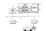
图1是显示根据本发明的一个具体实施例的车辆检测管理系统的示意图;Fig. 1 is a schematic diagram showing a vehicle detection management system according to a specific embodiment of the present invention;
图2是显示该具体实施例的服务器的硬件设施的方框图;Fig. 2 is a block diagram showing the hardware facilities of the server of this embodiment;
图3是显示该具体实施例的主管理终端的硬件设施的方框图;Fig. 3 is a block diagram showing the hardware facilities of the main management terminal of this specific embodiment;
图4是显示该具体实施例的移动检测终端的硬件设施的方框图;Fig. 4 is a block diagram showing the hardware facilities of the mobile detection terminal of this specific embodiment;
图5是显示通过该具体实施例的服务器执行的主要过程的流程图;Fig. 5 is a flowchart showing the main process performed by the server of this embodiment;
图6是显示通过该具体实施例的移动检测终端执行的主要过程的流程图。FIG. 6 is a flow chart showing the main process performed by the movement detection terminal of this specific embodiment.
图7是显示主数据输入屏的一个实例的视图,主数据输入屏用于通过具体实施例中的主管理终端确定标准检测时间的上限值和下限值;和Fig. 7 is the view showing an example of the main data input screen, and the main data input screen is used to determine the upper limit value and the lower limit value of the standard detection time by the main management terminal in the specific embodiment; and
图8是显示在具体实施例中的移动检测终端上显示的检测时间警告对话框的一个实例的视图。FIG. 8 is a view showing an example of a detection time warning dialog box displayed on the mobile detection terminal in the embodiment.
具体实施方式Detailed ways
接下来将参考附图解释本发明的具体实施例。Next, specific embodiments of the present invention will be explained with reference to the drawings.
图1是显示车辆检测管理系统的配置的示意图,该配置中服务器2和主管理终端3与设置在车辆制造厂的LAN相连,大量进入点4以预先设定的间隔连接到LAN 1上。用作检测终端的移动检测终端5位于进入点4附近,通过进入点4进行无线电通讯。1 is a schematic diagram showing a configuration of a vehicle detection management system in which a
检测工人6手持移动检测终端5,每当完成生产线上预先设定的过程时,检测工人操作移动检测终端5检测大量需要检测的装配在车辆7上的部分和零件。The
服务器2配备检测主数据库11和检测结果数据库12,还配备操作申请执行单元13,此单元用于执行记录标准检测时间的警告阈值的功能以及管理、比较、调查实际检测时间和警告次数等的功能。The
检测主数据库11包括被检测部分和零件的检测标准规格信息,检测标准的测量值等以及被制造车辆的识别代码,型号等。而且,各个检测项目的标准检测时间和发出警告的阈值通过使用操作申请执行单元13记录到检测主数据库11中。检测结果数据库12将各个移动检测终端5输入的实际检测时间和警告次数储存在一个检测屏上。The
如图2所示,服务器2配备CPU(中央处理单元)21,ROM(只读存储器)22,RAM(随机存取存储器)23,硬盘装置24,通讯单元25和操作单元26,它们通过总线27相互电连接。CPU 21控制各个元件,ROM 22用于储存CPU 21通过其控制各个元件的程序数据,RAM 23包括CPU21在发送、接收和处理数据等时临时使用的存储器,硬盘装置24用于储存检测主数据库11和检测结果数据库12等,通讯单元25通过LAN1与主管理终端3进行数据传接,以及通过LAN1和进入点4与移动检测终端5进行数据传接,操作单元26用于通过键盘、显示指示器等输入数据。As shown in Figure 2,
主管理终端3是生产线的管理者操作的终端。如图3所示,主管理终端3配备CPU31、ROM32、RAM33、通讯单元34、键盘35、显示器36、打印机37和硬盘装置38,它们通过总线39相互电连接。CPU31构成控制器主体,ROM32储存CPU31通过其控制各个元件的程序数据,RAM33包括CPU31在发送、接收和处理数据等时临时使用的存储器,还包括储存少量数据等的储存器,通讯单元34通过LAN1与服务器2进行数据传接,键盘35包括用于执行工作的各种按键,显示器36由液晶显示器等组成并显示数据等,打印机37打印和输出必要的数据,硬盘装置38用于储存大量的数据。The
如图4所示,移动检测终端5配备CPU51、ROM52、RAM53、液晶显示器54、触摸屏55和无线电通讯单元56,它们通过总线57相互电连接。CPU51构成控制器主体,ROM52储存CPU51通过其控制各个元件的程序数据,RAM53包括CPU51在发送、接收和处理数据等时临时使用的存储器,还包括储存少量数据等的储存器,液晶显示器54显示数据和在其上输入各种信息的输入屏,触摸屏55置于液晶显示器54上,通过触摸屏55在液晶显示器上显示的输入屏上输入信息,无线电通讯单元56利用无线电通讯与进入点4进行数据的传接。As shown in FIG. 4 , the mobile detection terminal 5 is equipped with a
指出对所制造车辆的哪些部分和零件在各个过程中进行何种类型检测的信息通过主管理终端3输入并记录到检测主数据库11。零部件经过焊接、油漆和装配后将在各个过程中进行检测。各种检测项目都有检测中使用的经输入的标准检测时间和报警阈值。Information indicating what type of inspection is performed on which parts and parts of manufactured vehicles in each process is input through the
当记录每个检测项目的标准检测时间时,主管理终端3将主数据输入屏显示在显示器36上。例如,当“轮胎牌号”的标准检测时间在输入屏上被输入和记录为标准检测工时数时,该标准检测时间被记录入检测主数据库11。When recording the standard detection time of each detection item, the
而且,当记录警告阈值时,如图7所示,主数据输入屏36b被显示在显示器36上以确定标准检测时间的上限和下限值。下限值设定成比标准时间短的时间,上限值设定成比标准时间长的时间。主数据输入屏36b显示,下限时间设定成标准检测时间的50%,上限时间设定成标准时间的500%。Also, when recording the warning threshold, as shown in FIG. 7, the main
焊接工作、油漆工作和装配工作等将在生产线的各个过程中相继执行,各个过程中所要执行的工作内容也在各过程中被检测。从主控制数据库11通过从移动检测终端5到服务器2的无线电通讯接收车辆制造某一过程中检测项目的信息,并将此信息显示在移动检测终端5上,检测工人据此执行检测。Welding work, painting work, assembly work, etc. will be performed successively in each process of the production line, and the content of work to be performed in each process is also checked in each process. The
在检测过程执行的检测工作中,如图5所示在步骤S1中服务器2确认是否有来自移动检测终端5的车辆接收的输入,在步骤S2中,服务器2从检测主数据库11中读出车辆在过程中的检测标准,并且将此标准传输到移动检测终端5(第一传送手段)。In the detection work that detection process is carried out, in step S1 as shown in Figure 5,
随后,在步骤S3中,服务器2在一个检测屏上从检测主数据库11中记录的各个检测项目的标准检测时间和报警阈值确定标准检测时间的上限和下限值,并且将此上下限值传送到移动检测终端5(第二传送手段)。Subsequently, in step S3, the
其后,在步骤4中,检测工人执行检测并且从移动检测终端5接收实际检测时间是否超过标准检测时间的上限与下限之间的范围的比较结果,当作为比较结果显示警告时,对于被警告的检测工人在检测主数据库11中警告次数增加1。Thereafter, in step 4, the detection worker performs the detection and receives the comparison result of whether the actual detection time exceeds the range between the upper limit and the lower limit of the standard detection time from the mobile detection terminal 5, when a warning is displayed as the comparison result, for the warned The number of warnings in the
移动检测终端5根据图6的流程图执行检测过程。即,在步骤S11中,移动检测终端5在液晶显示器54上显示车辆接收屏。然后,在步骤S12中,用于指定被检测车辆的数据在车辆接收屏上输入。在步骤S13,移动检测终端5将指定被检测车辆的数据传送到服务器2。The mobile detection terminal 5 executes the detection process according to the flowchart of FIG. 6 . That is, in step S11 , the movement detection terminal 5 displays the vehicle receiving screen on the
在此状态,在步骤S14中,移动检测终端5从服务器2接收被检测车辆的检测标准并且在液晶显示器54上显示检测屏(第一显示手段)。而后,在步骤S15,移动检测终端5在一个检测屏上从服务器2接收标准检测时间的上限和下限值。In this state, the mobile detection terminal 5 receives the detection standard of the detected vehicle from the
当在步骤S16中移动检测终端5确认检测开始时,在步骤S17中测量实际检测时间(时间测量手段)。值得注意的是实际检测时间通过设置带有RAM53的记时器测量,每次记时器记数例如1秒,实际检测时间加1。When the detection start is confirmed by the movement detection terminal 5 in step S16, the actual detection time is measured in step S17 (time measuring means). It should be noted that the actual detection time is measured by setting a timer with RAM53, and each time the timer counts for example 1 second, the actual detection time is increased by 1.
在步骤S18,当移动检测终端5确定与某一检测屏上显示的检测项目有关的检测结束时,在步骤19中通过从记时器测量的时间减去不包括于此项固定工作范围内的工作所花费的时间来确定实际净检测时间,不包括于此项固定工作范围内的工作所花费的时间例如操作屏幕所花的时间,该时间不管它是否与检测直接有关都会在检测期间显示。In step S18, when the mobile detection terminal 5 determines that the detection related to the detection item displayed on a certain detection screen ends, in
随后,在步骤S20中,移动检测终端5确定实际检测时间是否超出标准检测时间的上限于下限值之间的范围。当实际检测时间超出该范围,在步骤S21移动检测终端5在液晶显示器54上作为检测时间警告对话屏54b显示一个警告,(第二显示手段)。然后,在步骤S22中移动检测终端5将比较结果传送到服务器2中。Subsequently, in step S20, the mobile detection terminal 5 determines whether the actual detection time exceeds the range between the upper limit and the lower limit of the standard detection time. When the actual detection time exceeds the range, the mobile detection terminal 5 displays a warning on the
在上述的设置中,移动检测终端5从服务器2接收车辆在过程中的检测屏并且将其在液晶显示器54上显示,于是检测屏上显示的检测项目的检测工作被执行。此时,检测各个显示的检测项目必须的标准检测时间显示在检测屏上。因此,检测工人就可以很方便地知道从现在开始可以花多少时间用于所执行的检测工作,而且,可以方便地使检测时间和标准时间大致匹配,因此可以防止检测工作不被充分执行。In the above-mentioned setting, the mobile detection terminal 5 receives the detection screen of the vehicle in process from the
当检测工作开始时,移动检测终端5利用记时器测量实际的检测时间。在各项所显示的检测项目的检测完成时,移动检测终端5通过从记时器测量的实际工作时间减去固定工作范围外的工作花费的时间来确定实际净检测时间。然后,移动检测终端5用从服务器2接收到的标准检测时间的上限和下限值进行比较,看实际净工作时间是否在该上限和下限值的范围内。When the detection work starts, the mobile detection terminal 5 utilizes a timer to measure the actual detection time. When the detection of each displayed detection item is completed, the mobile detection terminal 5 determines the actual net detection time by subtracting the time spent working outside the fixed working range from the actual working time measured by the timer. Then, the mobile detection terminal 5 compares the upper limit and the lower limit of the standard detection time received from the
比如,当上限值是标准检测时间“21”秒的500%时,标准检测时间的上限就是“105秒”,当下限值是50%时,标准检测时间的下限时间就是约“10秒”。在这种情况下,移动检测终端5确定实际检测时间是否在10秒到105秒的范围内。比如,当实际检测时间是7秒时,它超过了下限,据此移动检测终端5确定检测工作进行得太快。在这种情况下,如图8所示的检测时间警告对话屏显示在液晶显示器54上以警告检测工作进行得太快。For example, when the upper limit is 500% of the standard detection time "21" seconds, the upper limit of the standard detection time is "105 seconds", and when the lower limit is 50%, the lower limit of the standard detection time is about "10 seconds" . In this case, the mobile detection terminal 5 determines whether the actual detection time is within the range of 10 seconds to 105 seconds. For example, when the actual detection time is 7 seconds, it exceeds the lower limit, whereby the mobile detection terminal 5 determines that the detection work is performed too quickly. In this case, a detection time warning dialogue screen as shown in FIG. 8 is displayed on the
因此,检测工人可以知道他所做的检测工作太快。由于屏54b上显示了标准检测时间(标准工时),当前执行的检测工作所用的检测时间,以及检测时间与标准检测时间之间的差异,检测工人也能知道已进行的检测工作执行有多快。因此,检测时间能够容易地与标准检测时间大致匹配。通过上述安排,检测工人对遵循检测时间的认知能够提高,因此就能防止检测工作不被充分执行。Therefore, the inspection worker can know that he is doing inspection work too fast. Since the
由于向每个工人发出的警告的数量由服务器2的检测结果数据库12管理,就可以挑检出在预定期间受警告次数多的检测工人并特别劝告他们。Since the number of warnings issued to each worker is managed by the
需要特别注意的是,在该实施例中移动检测终端被用作检测终端,通讯由无线电通讯系统通过服务器2与进入点4进执行。然而,本发明并不仅仅局限于此,通过服务器2,LAN等连接的固定检测终端也可以使用。It should be particularly noted that in this embodiment the mobile detection terminal is used as the detection terminal, and the communication is performed with the entry point 4 via the
另外的优点和改进对于本领域的熟练人员而言是很容易实现的。因此,本发明在其更宽的方面不局限于本文所描述的具体细节和代表性的具体实施例。因此,可以进行各种修改而不背离由附后的权利要求及其等效物所定义的本发明的总体概念的精神和范围。Additional advantages and modifications will readily appear to those skilled in the art. Therefore, the invention in its broader aspects is not limited to the specific details and representative embodiments described herein. Accordingly, various modifications may be made without departing from the spirit and scope of the general concept of the invention as defined by the appended claims and their equivalents.
Claims (8)
Applications Claiming Priority (3)
| Application Number | Priority Date | Filing Date | Title |
|---|---|---|---|
| JP2004096547AJP4306510B2 (en) | 2004-03-29 | 2004-03-29 | Vehicle inspection management system |
| JP2004096549 | 2004-03-29 | ||
| JP2004096547 | 2004-03-29 |
Publications (2)
| Publication Number | Publication Date |
|---|---|
| CN1677944A CN1677944A (en) | 2005-10-05 |
| CN100438468Ctrue CN100438468C (en) | 2008-11-26 |
Family
ID=34991149
Family Applications (1)
| Application Number | Title | Priority Date | Filing Date |
|---|---|---|---|
| CNB2005100637129AExpired - Fee RelatedCN100438468C (en) | 2004-03-29 | 2005-03-29 | Vehicle inspection management system and method |
Country Status (4)
| Country | Link |
|---|---|
| US (1) | US7818105B2 (en) |
| JP (1) | JP4306510B2 (en) |
| CN (1) | CN100438468C (en) |
| DE (1) | DE102005014126B4 (en) |
Families Citing this family (12)
| Publication number | Priority date | Publication date | Assignee | Title |
|---|---|---|---|---|
| JP4370960B2 (en)* | 2004-03-29 | 2009-11-25 | 三菱自動車エンジニアリング株式会社 | Vehicle inspection management system |
| GB2432924A (en)* | 2005-09-30 | 2007-06-06 | Airmax Group Plc | Method of inspecting a vehicle |
| GB2434219B (en)* | 2005-11-15 | 2010-11-24 | P G Drives Technology Ltd | Networked modules |
| US8756230B2 (en)* | 2007-12-31 | 2014-06-17 | Atco Industries, Inc. | Quality validation method |
| US20100169053A1 (en)* | 2008-12-30 | 2010-07-01 | Caterpillar Inc. | Method for creating weldment inspection documents |
| EP2580718A1 (en)* | 2010-06-14 | 2013-04-17 | Verify DA | System and method for assuring a correct performance of a manual operation |
| US20140012748A1 (en)* | 2012-07-05 | 2014-01-09 | General Electric Company | Repair system and method |
| SE536699C2 (en)* | 2012-10-17 | 2014-06-03 | Scania Cv Ab | Systematic choice of vehicle specification |
| JP5782468B2 (en)* | 2013-01-31 | 2015-09-24 | 日本瓦斯株式会社 | Security inspection result automatic pass / fail judgment notification system and method |
| US11461789B2 (en) | 2017-04-28 | 2022-10-04 | FMReps Consulting Enterprises, LLC | System and process for digital certification of pre-owned vehicles and equipment |
| JP2019117091A (en)* | 2017-12-27 | 2019-07-18 | 株式会社バンザイ | Vehicle inspection line system |
| DE102019208862B4 (en)* | 2019-06-18 | 2021-12-30 | Volkswagen Aktiengesellschaft | Procedure for performing a test drive |
Citations (5)
| Publication number | Priority date | Publication date | Assignee | Title |
|---|---|---|---|---|
| US6070155A (en)* | 1995-01-12 | 2000-05-30 | Automated Vehicle Anaysis, Inc. | Integrated automated analysis and repair |
| JP2000266569A (en)* | 1999-03-17 | 2000-09-29 | Alpine Electronics Inc | Product inspection system |
| JP2002012177A (en)* | 2000-06-29 | 2002-01-15 | Isuzu Motors Ltd | Inspection score control system |
| JP2003146270A (en)* | 2001-11-08 | 2003-05-21 | Honda Motor Co Ltd | Shipping protection system and destination building passage confirmation system |
| CN1436683A (en)* | 1998-07-17 | 2003-08-20 | 本田技研工业株式会社 | Quality Control System for Vehicle Assembly Lines |
Family Cites Families (42)
| Publication number | Priority date | Publication date | Assignee | Title |
|---|---|---|---|---|
| JPS6361133A (en) | 1986-09-01 | 1988-03-17 | Honda Motor Co Ltd | Finished car pass/fail judgment device |
| US5036479A (en) | 1989-04-20 | 1991-07-30 | Trw Inc. | Modular automated avionics test system |
| JPH04321133A (en) | 1991-04-22 | 1992-11-11 | Mitsubishi Electric Corp | Trouble diagnosing device |
| US5541840A (en)* | 1993-06-25 | 1996-07-30 | Chrysler Corporation | Hand held automotive diagnostic service tool |
| JPH07182423A (en) | 1993-12-24 | 1995-07-21 | Honda Motor Co Ltd | Manufacturing control system |
| US5839112A (en)* | 1994-12-28 | 1998-11-17 | Automatic Data Processing | Method and apparatus for displaying and selecting vehicle parts |
| US5717595A (en)* | 1995-01-12 | 1998-02-10 | Cherrington; John K. | Integrated automated vehicle analysis |
| US5754451A (en)* | 1996-02-29 | 1998-05-19 | Raytheon Company | Preventative maintenance and diagonstic system |
| US6405111B2 (en)* | 1997-05-16 | 2002-06-11 | Snap-On Technologies, Inc. | System and method for distributed computer automotive service equipment |
| DE19725916A1 (en) | 1997-06-19 | 1999-01-28 | Daimler Benz Ag | Computer=aided diagnosis device for electronically-controlled systems in motor vehicle |
| JPH1137903A (en)* | 1997-07-18 | 1999-02-12 | Honda Motor Co Ltd | Diagnostic device for electronic control unit |
| JP3792913B2 (en)* | 1997-11-17 | 2006-07-05 | 株式会社東芝 | Maintenance check support device |
| CA2280414C (en) | 1999-08-03 | 2000-10-31 | Honda Canada Inc. | Zone inspection manufacturing line |
| US6516239B1 (en) | 1999-08-03 | 2003-02-04 | Honda Of Canada Incorporated | Assembly line control system |
| US6801821B2 (en)* | 1999-08-03 | 2004-10-05 | Honda Canada Incorporated | Assembly line control system |
| US6370454B1 (en)* | 2000-02-25 | 2002-04-09 | Edwin S. Moore Iii | Apparatus and method for monitoring and maintaining mechanized equipment |
| JP2001350970A (en) | 2000-06-08 | 2001-12-21 | Dainippon Printing Co Ltd | Production status presentation system |
| US20020016655A1 (en)* | 2000-08-01 | 2002-02-07 | Joao Raymond Anthony | Apparatus and method for processing and/or for providing vehicle information and/or vehicle maintenance information |
| US7092803B2 (en)* | 2000-08-18 | 2006-08-15 | Idsc Holdings, Llc | Remote monitoring, configuring, programming and diagnostic system and method for vehicles and vehicle components |
| JP3898428B2 (en)* | 2000-09-07 | 2007-03-28 | 本田技研工業株式会社 | Tact setting method for vehicle assembly line |
| AU2001289056A1 (en)* | 2000-09-11 | 2002-03-26 | Pinotage, Llc | System and method for obtaining and utilizing maintenance information |
| JP3879968B2 (en)* | 2000-09-21 | 2007-02-14 | 本田技研工業株式会社 | Vehicle assembly system and vehicle assembly method |
| JP2002202810A (en)* | 2000-12-28 | 2002-07-19 | Toshiba Corp | Device management method, device management system, and recording medium storing device management program |
| JP2002243591A (en)* | 2001-02-22 | 2002-08-28 | Mitsubishi Electric Corp | Vehicle failure diagnosis device |
| US7127409B2 (en)* | 2001-03-01 | 2006-10-24 | General Electric Company | Methods and systems for aviation nonconformance component management |
| EP2381398A1 (en)* | 2001-04-25 | 2011-10-26 | Hitachi Construction Machinery Co., Ltd. | Construction machine management apparatus and construction machines management system |
| US6985786B2 (en)* | 2001-04-25 | 2006-01-10 | Hewlett-Packard Development Company, L.P. | Method for managing manufacturing data |
| JP2002323409A (en) | 2001-04-26 | 2002-11-08 | Fuji Heavy Ind Ltd | Vehicle management system |
| WO2002093438A1 (en)* | 2001-05-15 | 2002-11-21 | Akzo Nobel N.V. | Fleet servicing method |
| JP4798901B2 (en)* | 2001-09-05 | 2011-10-19 | 日立建機株式会社 | Work machine maintenance system |
| JP2003131885A (en)* | 2001-10-24 | 2003-05-09 | Denso Corp | Program writing system for in-vehicle electronic control unit |
| US6859677B2 (en)* | 2001-10-25 | 2005-02-22 | International Truck Intellectual Property Company, Llc | Assembly verification method and inspection system |
| JP2003157108A (en) | 2001-11-21 | 2003-05-30 | Mitsubishi Electric Corp | Production line inspection system |
| WO2003077073A2 (en)* | 2002-03-08 | 2003-09-18 | Fleettrakker, L.L.C. | Equipment tracking system and method |
| US6934596B2 (en) | 2002-03-18 | 2005-08-23 | Seiko Epson Corporation | Manufacturing system, measurement data collecting system, and measurement terminal apparatus |
| JP4057323B2 (en) | 2002-03-27 | 2008-03-05 | 本田技研工業株式会社 | System for handling specific information in vehicle inspection |
| JP2003295934A (en) | 2002-04-05 | 2003-10-17 | Denso Corp | Inspection system |
| US6876950B2 (en)* | 2002-04-26 | 2005-04-05 | The Boeing Company | System and method for damage evaluation |
| EP1570248A1 (en)* | 2002-11-07 | 2005-09-07 | Snap-on Technologies, Inc. | Vehicle data stream pause on data trigger value |
| US6917890B2 (en)* | 2003-05-29 | 2005-07-12 | Delphi Technologies, Inc. | Method to provide off-line transfer of vehicle calibration data |
| US7155324B2 (en)* | 2003-06-10 | 2006-12-26 | General Motors Corporation | Apparatus and method for programming motor vehicle electronic control units |
| US7132653B2 (en)* | 2004-01-07 | 2006-11-07 | Robert Carl Faubion | Apparatus for visual comparison of infrared images |
- 2004
- 2004-03-29JPJP2004096547Apatent/JP4306510B2/ennot_activeExpired - Lifetime
- 2005
- 2005-03-28USUS11/090,197patent/US7818105B2/enactiveActive
- 2005-03-29CNCNB2005100637129Apatent/CN100438468C/ennot_activeExpired - Fee Related
- 2005-03-29DEDE102005014126Apatent/DE102005014126B4/ennot_activeExpired - Fee Related
Patent Citations (5)
| Publication number | Priority date | Publication date | Assignee | Title |
|---|---|---|---|---|
| US6070155A (en)* | 1995-01-12 | 2000-05-30 | Automated Vehicle Anaysis, Inc. | Integrated automated analysis and repair |
| CN1436683A (en)* | 1998-07-17 | 2003-08-20 | 本田技研工业株式会社 | Quality Control System for Vehicle Assembly Lines |
| JP2000266569A (en)* | 1999-03-17 | 2000-09-29 | Alpine Electronics Inc | Product inspection system |
| JP2002012177A (en)* | 2000-06-29 | 2002-01-15 | Isuzu Motors Ltd | Inspection score control system |
| JP2003146270A (en)* | 2001-11-08 | 2003-05-21 | Honda Motor Co Ltd | Shipping protection system and destination building passage confirmation system |
Also Published As
| Publication number | Publication date |
|---|---|
| US20050216152A1 (en) | 2005-09-29 |
| DE102005014126A1 (en) | 2005-12-15 |
| JP4306510B2 (en) | 2009-08-05 |
| US7818105B2 (en) | 2010-10-19 |
| CN1677944A (en) | 2005-10-05 |
| JP2005280472A (en) | 2005-10-13 |
| DE102005014126B4 (en) | 2008-01-31 |
Similar Documents
| Publication | Publication Date | Title |
|---|---|---|
| CN100438468C (en) | Vehicle inspection management system and method | |
| EP0838788A1 (en) | System and method for managing time for vehicle fault diagnostic apparatus | |
| US9870690B2 (en) | Methods and systems for a universal wireless platform for asset monitoring | |
| CA2243444C (en) | Vehicle diagnosing apparatus | |
| US10437203B2 (en) | Methods and systems for dynamic workflow prioritization and tasking | |
| US20080180276A1 (en) | Verification of process variable transmitter | |
| JP4370960B2 (en) | Vehicle inspection management system | |
| EP2891564B1 (en) | Tire pressure sensor device setting method | |
| CN108226908A (en) | A kind of ultrasonic sensor remained shock and sensitivity test method and system | |
| JPH1194706A (en) | Vehicle diagnostic device | |
| JP5303435B2 (en) | Vehicle failure information management | |
| JP4801512B2 (en) | Rework measurement system and measurement method thereof | |
| JP7591799B2 (en) | FRAUD DETECTION DEVICE, FRAUD DETECTION METHOD, AND FRAUD DETECTION PROGRAM | |
| CN111143262A (en) | Switching device and instrument control system and instrument control method | |
| CN105164718A (en) | Information system and method for information processing, in particular for supporting work in a motor vehicle workshop | |
| JP4363240B2 (en) | Vehicle inspection management system | |
| JP4259382B2 (en) | Vehicle inspection management system | |
| JP2022122579A (en) | Vehicle assessment system, vehicle assessment method and vehicle assessment program | |
| JP2022090720A (en) | Maintenance inspection information management system | |
| JP4301056B2 (en) | Vehicle inspection management system | |
| US20240386755A1 (en) | Vehicle | |
| JP4258410B2 (en) | Vehicle inspection management system | |
| KR102592259B1 (en) | Method for diagnosing condition of dummy parts and device using the same | |
| JP2009140455A (en) | Operation history collection device and abnormality cause analysis support system | |
| CN119988389A (en) | A data updating method and related device |
Legal Events
| Date | Code | Title | Description |
|---|---|---|---|
| C06 | Publication | ||
| PB01 | Publication | ||
| C10 | Entry into substantive examination | ||
| SE01 | Entry into force of request for substantive examination | ||
| C14 | Grant of patent or utility model | ||
| GR01 | Patent grant | ||
| CP02 | Change in the address of a patent holder | ||
| CP02 | Change in the address of a patent holder | Address after:No.21, No.3, Dingmu, No.1, Zhipu, Tokyo, Japan Patentee after:Mitsubishi Jidosha Kogyo Kabushiki Kaisha Patentee after:MITSUBISHI JIDOSHA ENGINEERING Kabushiki Kaisha Address before:Tokyo Capital of Japan Patentee before:Mitsubishi Jidosha Kogyo Kabushiki Kaisha Patentee before:MITSUBISHI JIDOSHA ENGINEERING Kabushiki Kaisha | |
| CF01 | Termination of patent right due to non-payment of annual fee | ||
| CF01 | Termination of patent right due to non-payment of annual fee | Granted publication date:20081126 |