CN100435406C - Power supply apparatus - Google Patents
Power supply apparatusDownload PDFInfo
- Publication number
- CN100435406C CN100435406CCNB2004100817201ACN200410081720ACN100435406CCN 100435406 CCN100435406 CCN 100435406CCN B2004100817201 ACNB2004100817201 ACN B2004100817201ACN 200410081720 ACN200410081720 ACN 200410081720ACN 100435406 CCN100435406 CCN 100435406C
- Authority
- CN
- China
- Prior art keywords
- charging
- assembled battery
- voltage
- current
- battery
- Prior art date
- Legal status (The legal status is an assumption and is not a legal conclusion. Google has not performed a legal analysis and makes no representation as to the accuracy of the status listed.)
- Expired - Fee Related
Links
- 238000001514detection methodMethods0.000claimsabstractdescription12
- WHXSMMKQMYFTQS-UHFFFAOYSA-NLithiumChemical compound[Li]WHXSMMKQMYFTQS-UHFFFAOYSA-N0.000claimsdescription6
- 229910052744lithiumInorganic materials0.000claimsdescription6
- 230000003071parasitic effectEffects0.000description23
- 101150015217FET4 geneProteins0.000description18
- 230000002159abnormal effectEffects0.000description9
- 230000020169heat generationEffects0.000description7
- 238000010586diagramMethods0.000description3
- 230000006378damageEffects0.000description2
- 238000007599dischargingMethods0.000description2
- 230000005856abnormalityEffects0.000description1
- OJIJEKBXJYRIBZ-UHFFFAOYSA-Ncadmium nickelChemical compound[Ni].[Cd]OJIJEKBXJYRIBZ-UHFFFAOYSA-N0.000description1
- 230000007423decreaseEffects0.000description1
- 229910052987metal hydrideInorganic materials0.000description1
- 238000000034methodMethods0.000description1
- 229910052759nickelInorganic materials0.000description1
- PXHVJJICTQNCMI-UHFFFAOYSA-NnickelSubstances[Ni]PXHVJJICTQNCMI-UHFFFAOYSA-N0.000description1
- -1nickel metal hydrideChemical class0.000description1
Images


Classifications
- H—ELECTRICITY
- H02—GENERATION; CONVERSION OR DISTRIBUTION OF ELECTRIC POWER
- H02J—CIRCUIT ARRANGEMENTS OR SYSTEMS FOR SUPPLYING OR DISTRIBUTING ELECTRIC POWER; SYSTEMS FOR STORING ELECTRIC ENERGY
- H02J7/00—Circuit arrangements for charging or depolarising batteries or for supplying loads from batteries
- H02J7/007—Regulation of charging or discharging current or voltage
- H—ELECTRICITY
- H02—GENERATION; CONVERSION OR DISTRIBUTION OF ELECTRIC POWER
- H02J—CIRCUIT ARRANGEMENTS OR SYSTEMS FOR SUPPLYING OR DISTRIBUTING ELECTRIC POWER; SYSTEMS FOR STORING ELECTRIC ENERGY
- H02J7/00—Circuit arrangements for charging or depolarising batteries or for supplying loads from batteries
- H02J7/0013—Circuit arrangements for charging or depolarising batteries or for supplying loads from batteries acting upon several batteries simultaneously or sequentially
- H02J7/0014—Circuits for equalisation of charge between batteries
- H02J7/0019—Circuits for equalisation of charge between batteries using switched or multiplexed charge circuits
- H02J7/045—
Landscapes
- Engineering & Computer Science (AREA)
- Power Engineering (AREA)
- Charge And Discharge Circuits For Batteries Or The Like (AREA)
- Secondary Cells (AREA)
Abstract
Translated fromChinese
Description
Translated fromChinese技术领域technical field
本发明涉及包括将多个二次电池串联连接的组合电池和对该组合电池充电的充电电路的电源装置。The present invention relates to a power supply device including an assembled battery in which a plurality of secondary batteries are connected in series, and a charging circuit for charging the assembled battery.
背景技术Background technique
图1示出了内置串联连接着的多个电池23的组合电池21的电路图。该组合电池21内置防止各电池23过放电的过放电保护电路26。过放电保护电路26检测各电池23的电压,如果任何一个电池的电压比最低电压还低,则将放电电流切断FET24切换为截止。由于切换为截止的放电电流切断FET24切断放电电流,故停止放电。该组合电池21连接到充电器22进行充电。充电电流通过放电电流切断FET24的寄生二极管25流到电池23。因为放电电流切断FET24在逆方向为并联连接寄生二极管25的等效电路,故即使可以切断顺向的电流,也不能切断逆向的电流。因此,放电电流切断FET24即使处于在截止状态下禁止放电的状态,也成为可以通过充电电流的状态,成为可以给组合电池21充电的状态。FIG. 1 shows a circuit diagram of an assembled
但是,寄生二极管的缺点是:与电流沿顺向流过导通状态的FET的状态相比,电力损耗相当大。寄生二极管在沿顺向流过电流的状态下产生比较大的电压降。虽然寄生二极管的电力损耗与电压降和电流之积成比例增大,但寄生二极管的电压降比导通状态的放电电流切断FET大,寄生二极管的电力损耗变大。因此,如果在截止状态的FET中介由寄生二极管流过充电电流,以给组合电池充电,则FET的发热量显著变大。因此,会产生由给组合电池充电时的充电电流造成放电电流切断FET被热破坏或劣化等损害。However, the parasitic diode has a disadvantage in that power loss is considerably large compared with the state where the current flows in the forward direction through the FET in the on state. The parasitic diode generates a relatively large voltage drop in a state where current flows in the forward direction. Although the power loss of the parasitic diode increases in proportion to the product of the voltage drop and the current, the voltage drop of the parasitic diode is larger than that of the discharge current cutoff FET in the on state, and the power loss of the parasitic diode becomes larger. Therefore, when a charge current flows through the parasitic diode in the FET in the off state to charge the battery pack, the amount of heat generated by the FET is remarkably large. Therefore, the discharge current cut-off FET is thermally destroyed or deteriorated due to the charging current when the assembled battery is charged.
然而,作为充电器,正在开发:在充电前检测组合电池的输出电压,以输出电压的高低来控制充电电流的充电器。该充电器对于输出电压比设定电压还低的组合电池,不进行快速充电,而以小电流进行预充电,如果预充电后输出电压变得比设定电压还高,则切换到快速充电,以大电流进行充电。该充电器的特征是:由于不以大电流对因输出电压低而有可能故障了的组合电池进行快速充电,故可安全地给组合电池充电。However, as a charger, a charger that detects the output voltage of the assembled battery before charging and controls the charging current according to the level of the output voltage is being developed. This charger does not perform fast charging for combined batteries whose output voltage is lower than the set voltage, but pre-charges with a small current. If the output voltage becomes higher than the set voltage after pre-charging, it switches to fast charging. Charge with high current. The feature of this charger is that it can safely charge the assembled battery because it does not quickly charge the assembled battery that may fail due to low output voltage with a large current.
但是,如图1所示,即使为该充电器,若以各电池电压给将放电电流切断FET24切换为导通/截止的组合电池充电,则有时放电电流切断FET24在截止状态下开始快速充电。通常设定电压,以使FET充分导通之后才可以移动到快速充电。但是,会带来电池平衡崩溃的问题。例如,虽然任一个电池电压比最低电压还低,放电电流切断FET处于截止状态,但输出电压比开始快速充电的设定电压还高的组合电池从最初就被快速充电。任一个电池电压比最低电压还低的组合电池,输出电压比设定电压还低的可能性升高。但是,组合电池随着串联连接的二次电池的个数增多,一个电池的电压对输出电压的影响减小。因此,即使任一个电池电压比最低电压还低,组合电池整体的输出电压有时也比开始快速充电的设定电压还高。如果处于该状态的组合电池被快速充电,则处于截止状态的放电电流切断FET使充电电流流过寄生二极管。若寄生二极管中流过快速充电的大电流,则如前所述,放电电流切断FET的发热变大,成为热失控故障的原因。However, as shown in FIG. 1 , even with this charger, if the assembled battery in which the discharge
为了消除在放电电流切断FET的寄生二极管中因流过大电流而发热的弊端,正在开发将截止状态的放电电流切断FET切换到导通并进行快速充电的装置(参照专利文献1)。In order to eliminate the problem of heat generated by a large current flowing through the parasitic diode of the discharge current cutoff FET, a device that switches the discharge current cutoff FET in the off state to on for rapid charging is being developed (see Patent Document 1).
【专利文献1】【Patent Document 1】
特开2001-57743号公报Japanese Patent Application Publication No. 2001-57743
该公报中记载的装置,在对使放电电流切断FET为截止状态的组合电池进行充电时,将放电电流切断FET从截止切换到导通并快速充电。由于在该状态下被快速充电的组合电池没有寄生二极管,而是介由导通状态的放电电流切断FET通电,故可以消除由寄生二极管造成的发热。由于与寄生二极管并联连接的导通状态的放电电流切断FET与寄生二极管相比,电压降很小,故电力消耗减少。The device described in this publication switches the discharge current cut-off FET from off to on when charging an assembled battery with the discharge current cut-off FET turned off, and rapidly charges the battery. In this state, the assembled battery that is rapidly charged does not have a parasitic diode, but energizes the cut-off FET through the discharge current in the on-state, so heat generation caused by the parasitic diode can be eliminated. Since the on-state discharge current cut-off FET connected in parallel with the parasitic diode has a smaller voltage drop than the parasitic diode, the power consumption is reduced.
但是,由于该装置是将截止状态的放电电流切断FET强制切换为导通状态并以大电流快速充电,故即使可以防止FET的发热,也不能安全地给所有的组合电池充电。这是因为对任何一个电池电压比最低电压还低的组合电池都以大电流进行快速充电的缘故。电池电压比最低电压还低的电池是异常电池或是深度放电过的电池中的一种。不是异常电池而仅仅是深度放电过的电池,若以小电流进行预充电,则使电池电压变得比最低电压还高。电池本身存在异常的电池,即使预充电,电池电压也不会变得比最低电压还高。因此,任何一个电池电压比最低电压还低的电池最初均以小电流预充电,确认了所有的电池电压均比最低电压还高后,也就是说在确认不是异常电池后可快速充电。但是,在充电时将放电电流切断FET强制从截止切换到导通并快速充电的装置,具有因对包含异常电池的组合电池快速充电而造成的不能安全充电的缺点。However, since this device switches the discharge current cutoff FET in the off state to the on state forcibly and charges it quickly with a large current, even if it can prevent the heat generation of the FET, it cannot safely charge all the assembled batteries. This is because any combined battery whose battery voltage is lower than the minimum voltage is quickly charged with a large current. A battery whose battery voltage is lower than the minimum voltage is one of abnormal batteries or deeply discharged batteries. If a battery that is not an abnormal battery but is only deeply discharged is precharged with a small current, the battery voltage will become higher than the minimum voltage. There is an abnormality in the battery itself, and the battery voltage does not become higher than the minimum voltage even after precharging. Therefore, any battery whose voltage is lower than the minimum voltage is initially precharged with a small current, and after it is confirmed that all the battery voltages are higher than the minimum voltage, that is, it can be quickly charged after it is confirmed that it is not an abnormal battery. However, a device that forcibly switches the discharge current cutoff FET from off to on during charging and charges quickly has a disadvantage that safe charging cannot be performed due to rapid charging of an assembled battery including an abnormal battery.
发明内容Contents of the invention
本发明是以进一步解决该缺点为目的而进行开发的。本发明的重要目的是提供一种由组合电池和充电电路组成的电源装置,该装置对包含异常电池或与其他电池相比电池电压低的电池的组合电池进行安全充电的同时,可有效防止由寄生二极管的发热造成的FET故障。The present invention was developed for the purpose of further solving this disadvantage. An important object of the present invention is to provide a power supply device composed of an assembled battery and a charging circuit, which can effectively prevent the battery from FET failure due to heat generation of parasitic diodes.
本发明的电源装置具备:内置串联连接了多个二次电池3的组合电池1、和为该组合电池充电的充电电路9。组合电池1具备:与二次电池3串联连接并切断放电电流的放电电流切断FET4;和将各电池电压与最低电压比较,若任何一个电池电压比最低电压还低,则将放电电流切断FET4从导通切换到截止,以切断放电电流的最低电压检测部6。充电电路9具备充电电流切换部10,该充电电流切换部检测组合电池1的输出电压,切换充电电流,以便在输出电压比设定电压还高时进行主充电,在比设定电压还低时以比主充电还小的电流进行预充电。再者,组合电池1和充电电路9由将表示放电电流切断FET4的截止状态的截止信号传送到充电电流切换部10的信号线11连接,同时,充电电流切换部10在从信号线11输入截止信号的状态中,即使在组合电池1的输出电压比设定电压还高的状态下也要进行预充电。The power supply device of the present invention includes an assembled
充电电流切换部10在组合电池1的输出电压比设定电压还高的状态中,而且从信号线11没有输入截止信号的状态下,可使组合电池1的充电状态成为主充电状态。The charging current switching unit 10 can change the charging state of the assembled
充电电路2可将主充电中的充电电流设为0.5~4C,将预充电的充电电流设为小于主充电的充电电流。The
组合电池1可具备相互串联连接而成的锂电池。而且,组合电池1可用作自行车的电动机驱动用或电动工具用。The assembled
本发明的电源装置的特长是:在对包含异常电池或与其他电池相比电池电压低的电池的组合电池进行安全充电的同时,可有效防止由寄生二极管的发热造成的FET故障。这是因为本发明的电源装置检测组合电池1的输出电压,由充电电路的充电电流切换部切换充电电流,以便在输出电压比设定电压还高时进行主充电,在比设定电压还低时以比主充电还小的电流进行预充电,该充电电流切换部在组合电池的任何一个电池电压比最低电压还低的状态下,即使在组合电池的输出电压比设定电压还高的状态下也可进行预充电。该结构的电源装置即使在组合电池的输出电压比设定电压还高的状态下,任何一个电池电压比最低电压还低的状态、即放电电流切断FET为截止的状态下不进行主充电,而是以比主充电还小的电流进行预充电。因此,可防止在截止状态的放电电流切断FET中流过大的充电电流,可有效防止主充电中的放电电流切断FET的热破坏。The power supply device of the present invention is characterized in that it can effectively prevent FET failures caused by heat generation of parasitic diodes while safely charging assembled batteries including abnormal batteries or batteries with a lower battery voltage than other batteries. This is because the power supply device of the present invention detects the output voltage of the assembled
再者,本发明的电源装置在放电电流切断FET截止的状态下,不像现有的组合电池那样将放电电流切断FET从截止切换到导通并以大充电电流进行主充电,而是以比主充电还小的电流进行预充电。因此,对任何一个电池电压比最低电压还低的电池最初均以小电流预充电,在确认了所有的电池电压均比最低电压还高后,也就是说在确认了不是异常电池后可充电。因此,本发明的电源装置的特长是对于包含异常电池的组合电池从最初开始就不以大充电电流进行充电,可安全充电。Furthermore, the power supply device of the present invention does not switch the discharge current cut-off FET from off to on and perform main charging with a large charging current as in the conventional assembled battery when the discharge current cut-off FET is off, but instead The main charge is also pre-charged with a small current. Therefore, any battery whose voltage is lower than the minimum voltage is initially precharged with a small current, and can be charged after confirming that all the battery voltages are higher than the minimum voltage, that is, after confirming that it is not an abnormal battery. Therefore, the feature of the power supply unit of the present invention is that it can safely charge an assembled battery including an abnormal battery without charging it with a large charging current from the beginning.
附图说明Description of drawings
图1是现有的内置多个电池的组合电池的电路图。FIG. 1 is a circuit diagram of a conventional assembled battery with a plurality of built-in batteries.
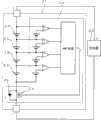
图2是本发明的一实施例的电源装置的电路图。FIG. 2 is a circuit diagram of a power supply device according to an embodiment of the present invention.
图3是本发明的一实施例的电源装置为组合电池充电的流程图。FIG. 3 is a flow chart of charging an assembled battery by a power supply device according to an embodiment of the present invention.
图中:1-组合电池,2-充电器,3-二次电池,4-放电电流切断FET,5-寄生二极管,6-最低电压检测部,7-比较器,8-AND电路,9-充电电路,10-充电电流切换部,11-信号线,21-组合电池,22-充电器,23-电池,24-放电电流切断FET,25-寄生二极管,26-过电流保护电路。In the figure: 1-combined battery, 2-charger, 3-secondary battery, 4-discharge current cut-off FET, 5-parasitic diode, 6-minimum voltage detection part, 7-comparator, 8-AND circuit, 9- Charging circuit, 10-charging current switching unit, 11-signal line, 21-combined battery, 22-charger, 23-battery, 24-discharging current cutoff FET, 25-parasitic diode, 26-overcurrent protection circuit.
具体实施方式Detailed ways
以下根据附图说明本发明的实施例。其中,以下所示的实施例示出了将用来本发明的技术思想具体化的电源装置,本发明并不将电源装置特定为以下情况。Embodiments of the present invention will be described below with reference to the drawings. In addition, the following embodiment shows the power supply device which embodied the technical idea used for this invention, and this invention does not specify a power supply device as the following.
而且,本说明书为了便于理解技术方案范围,将对应于实施例所示的部件的标号标记在“技术方案的范围”及“用于解决课题的方法栏”的部件上。但决非将技术方案的范围所示的部件特定为实施例的部件。In addition, in this specification, in order to facilitate understanding of the scope of the invention, symbols corresponding to members shown in the embodiments are attached to the members in the "scope of invention" and "means to solve the problems" column. However, the components shown in the scope of the claims are by no means specified as the components of the embodiment.
图2所示的电源装置具备:组合电池1和为该组合电池1充电的充电器2。组合电池1备有:与二次电池3串联连接并切断放电电流的放电电流切断FET4;和将各电池电压与最低电压比较,若任何一个电池电压比最低电压还低,则将放电电流切断FET4从导通切换到截止,以切断放电电流的作为过放电检测部的最低电压检测部6。组合电池1可以从充电器2取下,可作为另外准备的电气设备(没有图示)的电源使用。The power supply unit shown in FIG. 2 includes an assembled
二次电池3是相互串联连接着的锂电池。图中的组合电池1串联连接有4个锂电池。组合电池1,若串联连接的二次电池3的个数增多则输出电压变高。因此,相对于输出电压的一个电池电压变小。例如将串联连接2个电池的组合电池,一个电池电压收纳为输出电压的50%,但串联连接有4个电池的组合电池,一个电池电压成为输出电压的25%。因此,无论任何一个电池电压比最低电压还低,组合电池的输出电压比设定电压还高的概率随电池的串联连接个数增多而变大。由于本发明在该状态下可防止寄生二极管5的异常发热,故对于电池的串联连接个数多的组合电池特别有效。因此,本发明将例如3个以上、希望4个以上、最好5个以上的电池串联连接。The
使电池为锂电池的组合电池内置有检测各电池电压并控制过充放电的保护电路。因此,本发明对使电池为锂电池的组合电池特别有效。当然也可使电池为镍氢电池和镍镉电池。The assembled battery in which the battery is a lithium battery has a built-in protection circuit that detects the voltage of each battery and controls overcharge and discharge. Therefore, the present invention is particularly effective for an assembled battery in which the battery is a lithium battery. Of course, the battery can also be a nickel metal hydride battery or a nickel cadmium battery.
放电电流切断FET4是在截止状态切断放电电流,在导通状态保持能放电的状态的FET。放电电流切断FET4可切断放电电流,但不能切断充电电流。这是因为成为在逆向上并联连接寄生二极管5的等效电路的缘故。放电电流切断FET4是在逆向上并联连接有寄生二极管的FET、例如MOSFET。图中的组合电池1只将切断放电电流的放电电流切断FET4与二次电池3串联连接,但也可以将切断充电电流的充电电流切断FET与二次电池串联连接。若任何一个电池上升到充电禁止电压,或组合电池的输出电压上升到充电禁止电压,则充电电流切断FET便切换到截止状态并切断组合电池的充电电流。充电电流切断FET也是并联连接寄生二极管而成的MOSFET。因此,在充电电流切断FET呈截止状态,充电电流被切断的状态下,介由寄生二极管达到可放电的状态。The discharge
最低电压检测部6具备:检测各电池电压并与最低电压进行比较的比较器7;和若从任何一个比较器7输出截止信号,则输出截止信号的AND电路8。The lowest
比较器7是比较器,在负输入端子输入与最低电压相等的电压值的基准电压,在正输入端子输入电池电压。各二次电池3将负侧连接于基准电压的负侧,将正侧连接于比较器7的输入端子。该比较器7在电池电压比基准电压还高时,作为导通信号输出“High”,当电池电压比基准电压还低时,作为截止信号输出“Low”。The
如果从任何一个比较器7输出作为截止信号的“Low”,则AND电路8在输出端子输出将放电电流切断FET4置于截止的截止信号。因此,如果任何一个电池电压比最低电压还低,比较器7输出截止信号,则AND电路8输出截止信号,以将放电电流切断FET4切换为截止。在该状态下,放电电流切断FET4将放电电流切断,使组合电池不能放电。AND电路8只在所有输入端子输入作为导通信号的“High”时,才输出将放电电流切断FET4置于导通的导通信号。因此,在所有的电池电压均比最低电压还高、所有比较器7均输出导通信号的状态下,AND电路8输出导通信号,将放电电流切断FET4置于导通状态,成为可以使组合电池1放电的状态。If "Low" is output as an off signal from any one of the
充电电路9具备以组合电池1的输出电压来控制充电电流的充电电流切换部10。在将组合电池1安装于充电器2上时,充电电流切换部10检测组合电池1的输出电压,切换充电电流,以便在输出电压比设定电压还高时以大电流进行主充电并快速充电,在比设定电压还低时,以比主充电还小的电流进行预充电。充电器2以主充电为组合电池1快速充电。因此,主充电中的组合电池1的充电电流例如为0.5C~4C,最好是0.5C~2C。主充电的充电电流从给完全放电过的电池充满电所要的时间开始进行特定。如果将主充电电流设为1C,则从完全放电到充满电的时间为1小时。因此,设主充电的电流为上述范围,用2小时~15分钟或30分钟,可将完全放电过的组合电池1充满电。考虑到为异常电池充电,将预充电的充电电流设为小于主充电的充电电流,例如为0.1~0.5C。The charging
组合电池1和充电电路9由将表示放电电流切断FET4的截止状态的截止信号从组合电池1传送到充电器2的信号线11连接。信号线11将截止信号从组合电池1的最低电压检测部6传送到充电器2的充电电流切换部10。由于信号线11将表示放电电流切断FET4处于截止状态的截止信号传送到组合电池1的充电电流切换部10,故也可以是可将放电电流切断FET4的截止信号传送到充电电流切换部10的所有连接状态,例如放电电流切断FET的输入侧的截止信号被输入到充电器的充电电流切换部的连接状态。由于图2的电源装置将最低电压检测部6连接到放电电流切断FET4的输入侧,故将最低电压检测部6和放电电流切断FET4二者连接到充电器2的充电电流切换部10。The assembled
信号线11如图2所示,由导线将最低电压检测部6的输出侧连接到充电电流切换部10,将截止信号传送到充电电流切换部10,或者虽然图中未示出,但在导线的中间设置光耦合器等,介由光可将截止信号传送到充电电流切换部。通过信号线11,若将组合电池1的放电电流切断FET4处于截止状态的情况传送到充电器2的充电电流切换部10,则充电器2的充电电流切换部10,即使在组合电池1的输出电压比设定电压还高的状态,也不进行主充电,而是进行预充电。即,充电电流切换部10只在满足以下两个条件(1)和(2)时,对组合电池1进行主充电。As shown in Figure 2, the signal line 11 connects the output side of the lowest
(1)组合电池1的输出电压比设定电压还高。(1) The output voltage of the assembled
(2)放电电流切断FET4不是截止状态,也就是说放电电流切断FET4为导通状态。(2) The discharge current cutoff FET4 is not in an off state, that is, the discharge current cutoff FET4 is in an on state.
即使组合电池1的输出电压比设定电压还高,充电器2的充电电流切换部10在介由信号线11输入放电电流切断FET4的截止信号时,也不进行主充电,而是进行预充电。如果组合电池1被预充电且所有的电池电压比最低电压检测部6还高,则放电电流切断FET4从截止切换到导通。因此,信号线11不将截止信号从组合电池1传送到充电器2。如果成为该状态,则充电电流切换部10确认组合电池1的输出电压比设定电压还高,且放电电流切断FET4不是截止状态而是导通状态,将预充电切换成主充电,以大电流给组合电池1快速充电。Even if the output voltage of the assembled
在该状态下,以主充电进行快速充电的组合电池1使放电电流切断FET4的发热变小。这是因为处于导通状态的放电电流切断FET4的实际内部电阻与寄生二极管5的内部电阻相比相当小的缘故。因此,给组合电池1快速充电的大电流大部分通过低电阻的放电电流切断FET4,放电电流切断FET4的发热量变小。放电电流切断FET4的发热量与放电电流切断FET4的两端产生的电压降和电流之积成正比。电压降与内部电阻和电流之积成正比。内部电阻小的放电电流切断FET4电压降小。因此,该状态的放电电流切断FET4的发热减少,可有效防止大充电电流的主充电中的热破坏。In this state, the assembled
再者,虽然没有图示,但充电器2内置有控制组合电池的充电的控制电路。控制电路以图3所示的以下步骤给组合电池充电。In addition, although not shown, the
〔n=1的步骤〕[step for n=1]
充电器2的控制电路判断是否连接了组合电池1,如果连接组合电池1,则进入下一步骤,如果没有连接组合电池1,则将充电置于截止状态,循环n=1和2的步骤。The control circuit of
〔n=3~5的步骤〕〔n=3~5 steps〕
如果连接组合电池1,则根据是否从信号线11输入截止状态,来判断放电电流切断FET4是处于截止状态还是处于导通状态。如果放电电流切断FET4处于截止状态,则在n=4步骤中进行预充电。如果放电电流切断FET4处于导通状态,则在下面的n=5步骤中,判断组合电池1的输出电压是否比设定电压还高,如果输出电压比设定电压还高,则进行主充电并快速充电,如果输出电压比设定电压还低则进行预充电。之后,循环n=1~6的步骤,以给组合电池充满电。而且,在本实施例中,组合电池是装卸式,也可以将组合电池和充电器一体化。这种情况下,在放电时,将组合电池和充电器进行电分离,并取出放电输出。When the assembled
Claims (5)
Translated fromChineseApplications Claiming Priority (3)
| Application Number | Priority Date | Filing Date | Title |
|---|---|---|---|
| JP2003434255 | 2003-12-26 | ||
| JP2003434255AJP2005192371A (en) | 2003-12-26 | 2003-12-26 | Power supply unit |
| JP2003-434255 | 2003-12-26 |
Publications (2)
| Publication Number | Publication Date |
|---|---|
| CN1638184A CN1638184A (en) | 2005-07-13 |
| CN100435406Ctrue CN100435406C (en) | 2008-11-19 |
Family
ID=34114170
Family Applications (1)
| Application Number | Title | Priority Date | Filing Date |
|---|---|---|---|
| CNB2004100817201AExpired - Fee RelatedCN100435406C (en) | 2003-12-26 | 2004-12-21 | Power supply apparatus |
Country Status (4)
| Country | Link |
|---|---|
| US (1) | US7528578B2 (en) |
| JP (1) | JP2005192371A (en) |
| CN (1) | CN100435406C (en) |
| GB (1) | GB2409591B (en) |
Families Citing this family (20)
| Publication number | Priority date | Publication date | Assignee | Title |
|---|---|---|---|---|
| JP2006200983A (en)* | 2005-01-19 | 2006-08-03 | Denso Corp | Semiconductor integrated circuit device and its test method |
| EP1882190B1 (en)* | 2005-05-13 | 2020-04-22 | Nxp B.V. | Battery power management in over-discharge situation |
| US7605568B2 (en)* | 2006-03-10 | 2009-10-20 | Atmel Corporation | Deep under voltage recovery in a battery pack |
| CN100488001C (en)* | 2006-03-15 | 2009-05-13 | 大唐移动通信设备有限公司 | Method and circuit for charging the overdischarging lithium battery by mobile terminal |
| JP5020530B2 (en)* | 2006-04-14 | 2012-09-05 | パナソニック株式会社 | Charging method, battery pack and charger thereof |
| DE102008000704A1 (en)* | 2007-04-24 | 2008-10-30 | Robert Bosch Gmbh | Power tool and device switch for a power tool |
| DE102007031568A1 (en)* | 2007-07-06 | 2009-01-08 | Robert Bosch Gmbh | Device, in particular charger device, for charging a rechargeable battery |
| GB2462467B (en)* | 2008-08-08 | 2013-03-13 | P G Drives Technology Ltd | A cell management system |
| US8988912B2 (en)* | 2008-10-23 | 2015-03-24 | Leach International Corporation | System and method for emulating an ideal diode in a power control device |
| US20100190052A1 (en)* | 2009-01-27 | 2010-07-29 | Umesh Rajani | Battery pack with high and low current discharge terminals |
| KR101146378B1 (en)* | 2010-06-09 | 2012-05-17 | 삼성에스디아이 주식회사 | Charging battery pack and system thererwith |
| JP5736694B2 (en)* | 2010-09-03 | 2015-06-17 | ソニー株式会社 | Control device and method, and power supply device |
| EP2712004B1 (en)* | 2011-05-18 | 2017-09-13 | Hitachi Automotive Systems, Ltd. | Electricity storage device |
| US9748784B2 (en)* | 2011-09-01 | 2017-08-29 | Echostar Technologies L.L.C. | Detecting batteries with non-uniform drain rates |
| US9421876B2 (en)* | 2011-12-09 | 2016-08-23 | Honda Motor Co., Ltd. | Electric vehicle charging apparatus |
| JP6673651B2 (en)* | 2015-06-30 | 2020-03-25 | ダイハツ工業株式会社 | Power supply for plasma reactor |
| CN105811549A (en)* | 2016-04-12 | 2016-07-27 | 中国船舶重工集团公司第七〇二研究所 | Storage battery charging-discharging circuit |
| US10944274B2 (en) | 2018-01-19 | 2021-03-09 | Microsoft Technology Licensing, Llc | Ideal diode function implemented with existing battery protection FETs |
| JP2020137287A (en)* | 2019-02-21 | 2020-08-31 | エイブリック株式会社 | Charge/discharge control circuit, charge/discharge control device and battery device |
| JP7668829B2 (en) | 2023-01-31 | 2025-04-25 | 本田技研工業株式会社 | Power supply control system and target devices |
Citations (4)
| Publication number | Priority date | Publication date | Assignee | Title |
|---|---|---|---|---|
| WO2001059905A1 (en)* | 2000-02-07 | 2001-08-16 | Fujitsu Limited | Charger and power unit of portable terminal |
| JP2001333542A (en)* | 2000-05-19 | 2001-11-30 | Fuji Electric Co Ltd | Charging device |
| JP2002017052A (en)* | 2000-06-29 | 2002-01-18 | Matsushita Electric Ind Co Ltd | Rechargeable battery charging circuit and charging method thereof |
| JP2003111295A (en)* | 2001-09-27 | 2003-04-11 | Nec Tokin Tochigi Ltd | Charger using battery pack function |
Family Cites Families (9)
| Publication number | Priority date | Publication date | Assignee | Title |
|---|---|---|---|---|
| JP3231801B2 (en)* | 1991-02-08 | 2001-11-26 | 本田技研工業株式会社 | Battery charger |
| FR2713019B1 (en)* | 1993-11-23 | 1995-12-22 | Thomson Csf | Method and device for monitoring and dynamic balancing of a pack of accumulator batteries. |
| FR2725849B1 (en)* | 1994-10-18 | 1996-12-20 | Accumulateurs Fixes | METHOD FOR REGULATING THE CHARGE OF AN ELECTRIC BATTERY ASSEMBLY AND ARRANGEMENT USING THE SAME |
| JP3981893B2 (en) | 1996-05-22 | 2007-09-26 | ソニー株式会社 | Battery pack, charger, charging system, and charging method |
| US6025695A (en)* | 1997-07-09 | 2000-02-15 | Friel; Daniel D. | Battery operating system |
| JPH11164488A (en) | 1997-11-26 | 1999-06-18 | Yamaha Motor Co Ltd | Charge/discharge controlling device for battery of motor-driven vehicle |
| TW393822B (en)* | 1997-12-03 | 2000-06-11 | Sony Corp | An information processing device and method and a transmission medium |
| JP2001057743A (en) | 1999-08-18 | 2001-02-27 | Matsushita Electric Ind Co Ltd | Battery protection device |
| US6866107B2 (en)* | 2000-10-13 | 2005-03-15 | Deka Products Limited Partnership | Method and device for battery load sharing |
- 2003
- 2003-12-26JPJP2003434255Apatent/JP2005192371A/enactivePending
- 2004
- 2004-12-21CNCNB2004100817201Apatent/CN100435406C/ennot_activeExpired - Fee Related
- 2004-12-22GBGB0428116Apatent/GB2409591B/ennot_activeExpired - Fee Related
- 2004-12-23USUS11/020,032patent/US7528578B2/ennot_activeExpired - Fee Related
Patent Citations (4)
| Publication number | Priority date | Publication date | Assignee | Title |
|---|---|---|---|---|
| WO2001059905A1 (en)* | 2000-02-07 | 2001-08-16 | Fujitsu Limited | Charger and power unit of portable terminal |
| JP2001333542A (en)* | 2000-05-19 | 2001-11-30 | Fuji Electric Co Ltd | Charging device |
| JP2002017052A (en)* | 2000-06-29 | 2002-01-18 | Matsushita Electric Ind Co Ltd | Rechargeable battery charging circuit and charging method thereof |
| JP2003111295A (en)* | 2001-09-27 | 2003-04-11 | Nec Tokin Tochigi Ltd | Charger using battery pack function |
Also Published As
| Publication number | Publication date |
|---|---|
| CN1638184A (en) | 2005-07-13 |
| US20050140334A1 (en) | 2005-06-30 |
| JP2005192371A (en) | 2005-07-14 |
| GB2409591A (en) | 2005-06-29 |
| GB0428116D0 (en) | 2005-01-26 |
| US7528578B2 (en) | 2009-05-05 |
| GB2409591B (en) | 2006-06-14 |
Similar Documents
| Publication | Publication Date | Title |
|---|---|---|
| CN100435406C (en) | Power supply apparatus | |
| CN101145686B (en) | electrical tools | |
| US7508171B2 (en) | Protection methods, protection circuits and protective devices for secondary batteries, a power tool, charger and battery pack adapted to provide protection against fault conditions in the battery pack | |
| KR101975395B1 (en) | Battery pack, and controlling method of the same | |
| JP5449840B2 (en) | Charge / discharge control circuit and power supply device | |
| CN110226275A (en) | Electrical system and for make electrical system be powered method | |
| JP5488877B2 (en) | Electric tool | |
| JP2010130768A (en) | Battery system | |
| US20150035356A1 (en) | Vehicle power source device and vehicle equipped with the power source device | |
| US8802257B2 (en) | Battery pack and driving method thereof | |
| CN102055221A (en) | Battery pack | |
| JP2010233358A (en) | Battery protection circuit, battery protection method, power supply unit, and program | |
| JP2008125199A (en) | Control method for battery pack | |
| JPH06276696A (en) | Over-discharge protective circuit of secondary battery | |
| JP2000102185A (en) | Secondary battery pack | |
| JP5064776B2 (en) | Pack battery | |
| JPH08265985A (en) | Charging method for pack battery | |
| JP2003230228A (en) | Method and circuit for protecting secondary battery | |
| CN102570513A (en) | The mutually exclusive control component of the charge and discharge switch of the battery management system | |
| KR101744374B1 (en) | Apparatus and method for preventing battery using protective circuit | |
| JP2004127532A (en) | Battery pack | |
| JP2001112182A (en) | Secondary battery protection circuit | |
| JPH10117443A (en) | Overcharge and overdischarge prevention device for secondary battery | |
| JP4130605B2 (en) | Secondary battery overcharge protection device, power supply device, and secondary battery charge control method | |
| CN220022388U (en) | Battery charge and discharge protection device |
Legal Events
| Date | Code | Title | Description |
|---|---|---|---|
| C06 | Publication | ||
| PB01 | Publication | ||
| C10 | Entry into substantive examination | ||
| SE01 | Entry into force of request for substantive examination | ||
| C14 | Grant of patent or utility model | ||
| GR01 | Patent grant | ||
| CF01 | Termination of patent right due to non-payment of annual fee | Granted publication date:20081119 Termination date:20141221 | |
| EXPY | Termination of patent right or utility model |