CN100435016C - electro-optic display - Google Patents
electro-optic displayDownload PDFInfo
- Publication number
- CN100435016C CN100435016CCNB200480031366XACN200480031366ACN100435016CCN 100435016 CCN100435016 CCN 100435016CCN B200480031366X ACNB200480031366X ACN B200480031366XACN 200480031366 ACN200480031366 ACN 200480031366ACN 100435016 CCN100435016 CCN 100435016C
- Authority
- CN
- China
- Prior art keywords
- electrophoretic medium
- display
- layer
- electrophoretic
- electro
- Prior art date
- Legal status (The legal status is an assumption and is not a legal conclusion. Google has not performed a legal analysis and makes no representation as to the accuracy of the status listed.)
- Expired - Lifetime
Links
Images


Landscapes
- Electrochromic Elements, Electrophoresis, Or Variable Reflection Or Absorption Elements (AREA)
Abstract
Translated fromChineseDescription
Translated fromChinese本发明涉及电光显示器以及用于生产这种显示器的方法和器件.如以下描述所显而易见的,本发明的一些方面限于电泳显示器,而其他方面可使用其他类型的电光显示器.更具体地说,本发明涉及(a)具有粘合剂的电光介质和显示器,所述粘合剂还可以作为叠层胶粘剂;(b)用于形成柔性显示器的方法;(c)彩色电光显示器;(d)用于形成电光显示器的方法和器件;和(e)用于制造由具有不同热膨胀系数的材料形成的混合显示器的方法.The present invention relates to electro-optic displays and methods and devices for producing such displays. As will be apparent from the following description, some aspects of the invention are limited to electrophoretic displays, while other aspects are applicable to other types of electro-optic displays. More specifically, this The invention relates to (a) electro-optic media and displays having adhesives that also serve as lamination adhesives; (b) methods for forming flexible displays; (c) color electro-optic displays; (d) for Methods and devices for forming electro-optic displays; and (e) methods for making hybrid displays formed from materials having different coefficients of thermal expansion.
本申请与以下专利和已经公开的申请相关,读者参考这些以获得更详细的背景资料:This application is related to the following patents and published applications, the reader is referred to these for more detailed background information:
(a)美国专利申请公布No.2002/0180688(参见相关的国际申请WO99/53373);(a) U.S. Patent Application Publication No. 2002/0180688 (see related International Application WO99/53373);
(b)美国专利申请公布No.2004/0136048;(b) U.S. Patent Application Publication No. 2004/0136048;
(c)美国专利申请公布No.2004/0027327(参见相关的国际申请WO03/104884);(c) US Patent Application Publication No. 2004/0027327 (see related International Application WO03/104884);
(d)美国专利申请公布No.2004/0155857(参见相关的国际申请WO2004/023195);(d) US Patent Application Publication No. 2004/0155857 (see related International Application WO2004/023195);
(e)美国专利No.6124851;(e) U.S. Patent No. 6,124,851;
(f)美国专利No.6721083;(f) U.S. Patent No. 6,721,083;
(g)美国专利No.6538801;(g) U.S. Patent No. 6,538,801;
(h)美国专利No.6323989;(h) U.S. Patent No. 6,323,989;
(i)美国专利No.6422687;和(i) U.S. Patent No. 6,422,687; and
(j)美国专利No.6120588.(j) U.S. Patent No. 6120588.
在本发明的显示器中,在电光介质具有固体外表面的意义上,尽管介质可以并且经常的确具有内部液体或气体填充的空间,以及在使用这种电光介质装配显示器的方法的意义上,电光介质(当非电泳电光介质时)将典型地是一种固体(这种显示器可以下为方便起见称为“固体电光显示器”).因而,术语“固体电光显示器”包括封装的电泳显示器、封装的液晶显示器及下述其他类型的显示器.In the displays of the invention, the electro-optic medium, in the sense that the electro-optic medium has a solid outer surface, although the medium may, and often does, have internal liquid or gas-filled spaces, and in the sense of the method of assembling a display using such an electro-optic medium, (When not an electrophoretic electro-optic medium) will typically be a solid (such displays may hereinafter be referred to as "solid-state electro-optic displays" for convenience). Thus, the term "solid-state electro-optic displays" includes encapsulated electrophoretic displays, encapsulated liquid crystal Displays and other types of displays described below.
如应用于材料或显示器的术语“电光”,在本文中以其在成像技术领域中常规意义使用,以指具有第一和第二显示状态的材料,所述显示状态在至少一个光学性质方面不同,通过对该材料施加电场,该材料从其第一显示状态变化为其第二显示状态.尽管光学性质典型地是人眼可感觉到的色彩,但它可是另一种光学性质,如光传输、反射率、发光,或者就意图机读的显示器来说,在可见区外电磁波长反射率方面变化的意义上的伪色.The term "electro-optic," as applied to materials or displays, is used herein in its conventional sense in the field of imaging technology to refer to materials having first and second display states that differ in at least one optical property , the material changes from its first display state to its second display state by applying an electric field to the material. While the optical property is typically color perceivable by the human eye, it can be another optical property such as light transmission , reflectivity, luminescence, or, in the case of displays intended to be machine readable, false color in the sense of a change in reflectivity at electromagnetic wavelengths outside the visible region.
术语“双稳态的”和“双稳定性”在本文中以其在本领域中常规意义使用,是指包括具有第一和第二显示状态的显示元件的显示器,所述显示状态在至少一个光学性质方面不同,使得在任何给定的元件通过有限持续时间的寻址脉冲驱动后,呈现其第一或者第二显示状态,在该寻址脉冲终止以后,那个状态将持续至少若干次,例如至少四次,改变显示元件状态所要求的寻址脉冲的最小持续时间.在美国专利申请公布No.2002/0180687中表明一些可具有灰度标的粒子型电泳显示器不仅在其极限黑白状态中是稳定的,而且在其中间灰色状态中也是稳定的,并且其它类型的电光显示器的情况也是一样的.这类显示器恰当地称作“多稳态的”而不是双稳态的,不过为方便起见,可在本文中使用术语“双稳态的”以涵盖双稳态和多稳态显示器.The terms "bistable" and "bistable" are used herein in their conventional sense in the art to refer to a display comprising display elements having first and second display states in at least one differ in optical properties such that after any given element is driven by an addressing pulse of finite duration, assumes its first or second display state, and that state will persist at least several times after termination of the addressing pulse, e.g. At least four times, the minimum duration of addressing pulses required to change the state of a display element. It is shown in US Patent Application Publication No. 2002/0180687 that some particle-type electrophoretic displays that can have gray scales are stable not only in their extreme black and white states and is also stable in its intermediate gray state, and the same is true for other types of electro-optic displays. Such displays are properly called "multistable" rather than bistable, but for convenience, The term "bistable" may be used herein to cover both bistable and multistable displays.
几种类型的电光显示器是已知的.一种类型的电光显示器是旋转双色构件型,如在以下文献中描述:美国专利Nos.5808783、5777782、5760761、6054071、6055091、6097531、6128124、6137467和6147791(不过这类显示器经常被称为“旋转双色珠”显示器,由于更准确,术语“旋转双色构件”是优选的,因为上述一些专利中,旋转构件不是球形的).这种显示器使用大量小的物体(典型地是球形或圆柱形),所述物体具有两个或更多不同光学特性的段,和内部偶极子.这些物体在基质内悬浮在液体填充的液泡内,该液泡充满液体以便该物体任意旋转.向显示器施加电场,因此使这些物体旋转到不同的位置并且改变物体段的通过观察表面所见内容,从而改变显示器的显现.这类电光介质典型地是双稳态的.Several types of electro-optic displays are known. One type of electro-optic display is the rotary dichroic member type, as described in: U.S. Patent Nos. 6147791 (however this type of display is often referred to as a "rotating dichroic bead" display, the term "rotating dichroic member" is preferred as it is more accurate since in some of the above patents the rotating member is not spherical). This display uses a large number of small objects (typically spherical or cylindrical) that have two or more segments of different optical properties, and an internal dipole. These objects are suspended within a matrix within a liquid-filled vacuole filled with a liquid so that the object can be rotated arbitrarily. An electric field is applied to the display, thereby rotating the objects to different positions and changing what the object segments see through the viewing surface, thereby changing the appearance of the display. Such electro-optic media are typically bistable.
另一种类型的电光显示器使用电致色介质,例如以纳米发色(nanochromic)薄膜形式的电致色介质,其包括至少部分地由半导金属氧化物形成的电极和被连接到该电极的能够可逆变色的多个染料分子;见,例如O′Regan,B.,等人,Nature 1991,353,737;和Wood,D.,Information Display,18(3),24(2002年3月).还见Bach,U.,等人,Adv.Mater.,2002,14(11),845.这种类型的纳米发色薄膜还描述在,例如,美国专利No.6301038,国际申请公开No.WO 01/27690和美国专利申请2003/0214695.这类电光介质也典型地是双稳态的.Another type of electro-optic display uses an electrochromic medium, for example in the form of a nanochromic film, comprising an electrode formed at least in part of a semiconducting metal oxide and an electrode connected to the electrode. Multiple dye molecules capable of reversible color reversibility; see, for example, O'Regan, B., et al., Nature 1991, 353, 737; and Wood, D., Information Display, 18(3), 24 (2002 3 1). See also Bach, U., et al., Adv.Mater., 2002, 14(11), 845. This type of nano-chromogenic film is also described in, for example, U.S. Patent No.6301038, International Application Publication No. WO 01/27690 and US Patent Application 2003/0214695. Such electro-optic media are also typically bistable.
另一种类型的电光显示器(其多年来已经是大量研究与开发的主题)是粒子型电泳显示器,其中多个带电粒子在电场影响下通过悬浮液.当与液晶显示器相比,电泳显示器可具有优良的亮度和对比度、宽视角、状态双稳定性和低电耗的特征.然而,与这些显示器长期图像质量相关的问题已经妨碍其广泛的使用.例如,构成电泳显示器的粒子常常沉淀,导致这些显示器不足的使用寿命.Another type of electro-optic display (which has been the subject of considerable research and development over the years) is the particle-type electrophoretic display, in which a plurality of charged particles are passed through a suspension under the influence of an electric field. When compared with liquid crystal displays, electrophoretic displays can have Excellent brightness and contrast, wide viewing angles, state bistability, and low power consumption are characteristic. However, problems associated with the long-term image quality of these displays have prevented their widespread use. For example, the particles that make up electrophoretic displays often precipitate, causing these Insufficient lifespan of the display.
许多被转让于麻省理工学院(MIT)和E Ink公司或者以其名义的专利和申请最近被公开,其描述了封装的电泳介质.这种封装的介质包括许多小囊,每个小囊本身包括内相和囊壁,其中内相包含悬浮在液体悬浮介质中的可电泳移动的粒子,囊壁围绕该内相.典型地,囊本身固定在聚合物粘合剂内以形成位于二个电极之间的粘附层.这类封装介质描述于,例如,美国专利Nos.5930026;5961804;6017584;6067185;6118426;6120588;6120839;6124851;6130773;6130774;6172798;6177921;6232950;6249721;6252564;6262706;6262833;6300932;6312304;6312971;6323989;6327072;6376828;6377387;6392785;6392786;6413790;6422687;6445374;6445489;6459418;6473072;6480182;6498114;6504524;6506438;6512354;6515649;6518949;6521489;6531997;6535197;6538801;6545291;6580545;6639578;6652075;6657772;6664944;6680725;6683333;6704133;6710540;6721083;6727881;6738050;6750473;和6753999;以及美国专利申请公开Nos.2002/0019081;2002/0021270;2002/0060321;2002/0060321;2002/0063661;2002/0090980;2002/0113770;2002/0130832;2002/0131147;2002/0171910;2002/0180687;2002/0180688;2002/0185378;2003/0011560;2003/0020844;2003/0025855;2003/0038755;2003/0053189;2003/0102858;2003/0132908;2003/0137521;2003/0137717;2003/0151702;2003/0214695;2003/0214697;2003/0222315;2004/0008398;2004/0012839;2004/0014265;2004/0027327;2004/0075634;2004/0094422;2004/0105036;2004/0112750;和2004/0119681;和国际申请公开Nos.WO99/67678;WO00/05704;WO00/38000;WO00/38001;WO00/36560;WO00/67110;WO00/67327;WO01/07961;WO01/08241;WO03/107315;WO2004/023195;和WO2004/049045.A number of patents and applications have recently been published, assigned to or in the name of the Massachusetts Institute of Technology (MIT) and E Ink Corporation, which describe encapsulated electrophoretic media. Such encapsulated media consist of a number of capsules, each of which is itself Comprising an internal phase containing electrophoretically mobile particles suspended in a liquid suspending medium and a capsule wall surrounding the internal phase. Typically, the capsule itself is immobilized within a polymeric binder to form a Adhesive layer between. This type of packaging medium is described in, for example, U.S. Patent Nos.5930026; 5961804; 6017584; 6067185; 6262706;6262833;6300932;6312304;6312971;6323989;6327072;6376828;6377387;6392785;6392786;6413790;6422687;6445374;6445489;6459418;6473072;6480182;6498114;6504524;6506438;6512354;6515649;6518949;6521489; 6531997;6535197;6538801;6545291;6580545;6639578;6652075;6657772;6664944;6680725;6683333;6704133;6710540;6721083;6727881;6738050;6750473;和6753999;以及美国专利申请公开Nos.2002/0019081;2002/ 0021270; 2002/0060321; 2002/0060321; 2002/0063661; 2002/0090980; 2002/0113770; 2002/0130832; 2002/0131147; 2002/0171910; 2002/0180687; 2002/0180688; 2002/0185378; 2003/0011560; 2003/0020844;2003/0025855;2003/0038755;2003/0053189;2003/0102858;2003/0132908;2003/0137521;2003/0137717;2003/0151702;2003/0214695;2003/0214697;2003/0222315;2004/ 2004/0012839; 2004/0014265; 2004/0027327; 2004/0075634; 2004/0094422; 2004/0105036; 2004/0112750; /38000; WO00/38001; WO00/36560; WO00/67110; WO00/67327; WO01/07961; WO01/08241; WO03/107315; WO2004/023195;
已知的电泳介质,封装的和未封装的,可被分成两个主要类型,以下为方便起见分别称为“单粒子”和“双粒子”.A单粒子介质只具有单个类型的悬浮在悬浮介质中的电泳粒子,悬浮介质的至少一个光学特性不同于粒子的光学特性.(在谈及单个类型的粒子中,我们不意味着该类型的全部粒子绝对地相同.例如,假如该类型的全部粒子具有基本上相同的光学特性和相同极性的电荷,在不影响介质效用的条件下,参数如粒度和电泳迁移率的明显变化是可以允许的.)当这种介质被放置在一对电极间时,至少其中之一是透明的,取决于二个电极的相对电势,介质可显示该粒子的光学特性(当该粒子邻近于靠近观察者的电极,在下文称“前”电极)或该悬浮介质的光学特性(当该粒子邻近于远离观察者的电极,在下文称“后”电极,以便粒子通过悬浮介质而隐藏).Known electrophoretic media, encapsulated and unencapsulated, can be divided into two main types, hereinafter referred to for convenience as "single-particle" and "dual-particle", respectively. A single-particle medium has only a single type of suspension in suspension Electrophoretic particles in a medium in which at least one optical property of the suspending medium differs from that of the particle. (In speaking of a single type of particle, we do not mean that all particles of that type are absolutely identical. For example, if all Particles have essentially the same optical properties and charges of the same polarity, and significant variations in parameters such as particle size and electrophoretic mobility are permissible without affecting the utility of the medium.) When this medium is placed between a pair of electrodes At least one of them is transparent, depending on the relative potentials of the two electrodes, the medium can display the optical properties of the particle (when the particle is adjacent to the electrode close to the observer, hereinafter referred to as the "front" electrode) or the Optical properties of the suspension medium (when the particle is adjacent to an electrode away from the observer, hereinafter referred to as the "rear" electrode, so that the particle is hidden by the suspension medium).
双粒子介质具有两个不同类型的粒子以及悬浮液,所述粒子在至少一个光学特性方面不同,所述悬浮液可是未着色的或着色的,但其其型地是未着色的.该两个类型的粒子在电泳迁移率方面不同;在迁移率上的这种差异可以是在极性(此类型在下文可称为“相反电荷双粒子”介质)和/或数量方面.当这种双粒子介质被放置在上述一对电极之间,取决于该二个电极的相对电势,介质可显示任一类粒子的光学特性,尽管这种实现的具体方式的不同取决于迁移率的差异是在极性方面还是在数量方面.便于说明,考虑一种电泳介质,其中一个类型的粒子是黑色而另一个类型是白色.如果两个类型的粒子在极性方面不同(若,例如,黑色粒子是带正电,白色粒子带负电),这些粒子将被吸引到两个不同的电极,结果若,例如,相对于后电极,前电极是负极,黑色粒子将被吸引到前电极而白色粒子被吸引到后电极,结果该介质将向观察者呈现黑色.相反地,如果前电极相对于后电极是正极,白色粒子将被吸引到前电极而黑色粒子被吸引到后电极,结果介质将向观察者呈现白色.A dual particle medium has two different types of particles differing in at least one optical property and a suspension which may be uncolored or colored but which is typically uncolored. The two Types of particles that differ in electrophoretic mobility; this difference in mobility may be in polarity (this type may hereinafter be referred to as an "oppositely charged diparticle" medium) and/or in number. When such diparticle A medium is placed between the aforementioned pair of electrodes, and depending on the relative potentials of the two electrodes, the medium can exhibit the optical properties of either type of particle, although the exact manner in which this is achieved differs depending on the difference in mobility. either in terms of polarity or in terms of quantity. For illustration, consider an electrophoretic medium in which particles of one type are black and the other type is white. If the two types of particles differ in polarity (if, for example, black particles are positively charged, white particles negatively charged), these particles will be attracted to two different electrodes, so that if, for example, the front electrode is negative with respect to the back electrode, the black particles will be attracted to the front electrode and the white particles to the the rear electrode, as a result the medium will appear black to the observer. Conversely, if the front electrode is positive with respect to the rear electrode, white particles will be attracted to the front electrode and black particles to the rear electrode, and as a result the medium will appear black to the observer White.
如果两个类型的粒子具有相同极性的电荷,但是在电泳迁移率方面不同(这类介质可在下文称为“相同极性的双粒子”介质),两个类型的粒子将被吸引到相同的电极,但是一种类型将比另一种类型先到达电极,结果面向观察者的类型取决于粒子所被吸引到的电极而不同.例如假定,改变上述实例使得黑白粒子带正电,但黑色粒子具有更高的电泳迁移率.如果现在前电极相对于后电极是负极,黑白粒子将被吸引到前电极,但黑色粒子,因为其更高的迁移率,将首先到达前电极,结果黑色粒子层将涂敷前电极而该介质将向观察者呈现黑色.相反地,如果前电极相对于后电极是正极,黑白粒子将被吸引到后电极,但该黑色粒子,因为其更高的迁移率,将首先到达后电极,结果黑色粒子层将涂敷后电极,使得白色粒子层远离后电极而面对观察者,结果该介质将向观察者呈现白色:这类双粒子介质要求悬浮液是足够透明的使得白色粒子层远离后电极而容易地使观察者可见.典型地,在这种显示器中的悬浮液根本不是着色的,但一些色料可被结合,为了修正在通过其所见的白色粒子中任何不合需要的色泽.If two types of particles have the same polarity of charge, but differ in electrophoretic mobility (such media may be referred to hereinafter as "same polarity two-particle" media), the two types of particles will be attracted to the same , but one type will reach the electrode before the other, with the result that the type facing the viewer differs depending on which electrode the particle is attracted to. Suppose, for example, that changing the above example makes the black and white particles positively charged, but the black Particles have a higher electrophoretic mobility. If the front electrode is now negative with respect to the back electrode, black and white particles will be attracted to the front electrode, but black particles, because of their higher mobility, will reach the front electrode first, resulting in black particles layer will coat the front electrode and the medium will appear black to the observer. Conversely, if the front electrode is positive relative to the back electrode, black and white particles will be attracted to the back electrode, but the black particles, because of their higher mobility , will reach the rear electrode first, with the result that the layer of black particles will coat the rear electrode so that the layer of white particles faces away from the rear electrode and faces the observer, as a result the medium will appear white to the observer: this type of two-particle medium requires that the suspension be sufficient Transparent so that the layer of white particles is away from the rear electrode and easily visible to the observer. Typically, the suspension in such displays is not colored at all, but some colorants may be incorporated in order to correct the whiteness seen through it Any undesired tint in the particles.
单粒子和双粒子电泳显示器可能够具有中间灰色状态,该灰色状态具有介于两个已述极限光学状态中间的光学特性.Single-particle and two-particle electrophoretic displays may be capable of intermediate gray states with optical properties intermediate between the two extreme optical states already described.
一些上述专利而公开的申请公开了封装的电泳介质,其在每个囊内具有三个或更多不同类型的粒子.对本申请来说,这种多粒子介质被认为是双粒子介质的亚类.Published applications from some of the aforementioned patents disclose encapsulated electrophoretic media having three or more particles of different types within each capsule. For purposes of this application, such multi-particle media are considered a subclass of two-particle media .
许多上述专利和申请承认在封装的电泳介质中围绕离散的微胶囊的壁可被连续相代替,因而制造一种所谓的聚合物-分散的电泳显示器,其中电泳介质包括多个离散的电泳流体的小滴和聚合物材料的连续相,而且在这种聚合物-分散的电泳显示器内的电泳流体的离散小滴可被认为是囊或微胶囊,即使无离散囊膜与每个单独的小滴相联系;见例如,上述2002/0131147.因此,对本申请来说,这种聚合物-分散的电泳介质被认为是封装的电泳介质的亚类.Many of the aforementioned patents and applications recognize that the walls surrounding discrete microcapsules in an encapsulated electrophoretic medium can be replaced by a continuous phase, thus creating a so-called polymer-dispersed electrophoretic display, wherein the electrophoretic medium comprises a plurality of discrete electrophoretic fluids. droplets and a continuous phase of polymeric material, and the discrete droplets of electrophoretic fluid within such polymer-dispersed electrophoretic displays can be considered capsules or microcapsules, even though there is no discrete capsule membrane associated with each individual droplet related; see, e.g., 2002/0131147 above. Accordingly, for purposes of this application, such polymer-dispersed electrophoretic media are considered a subclass of encapsulated electrophoretic media.
一种电泳显示器相关类型是所谓的“微单元电泳显示器”.在微单元电泳显示器中,带电粒子和悬浮液不是封装在微胶囊内,而是保持在多个形成在载体介质内的腔中,典型地是聚合物薄膜.见,例如,国际申请公开No.WO02/01281,和公开的US申请No.2002/0075556,均转让于Sipix Imaging,Inc.A related type of electrophoretic display is the so-called "microcell electrophoretic display". In a microcell electrophoretic display, the charged particles and suspension are not encapsulated in microcapsules, but are held in multiple cavities formed in the carrier medium, Typically polymer films. See, e.g., International Application Publication No. WO02/01281, and Published US Application No. 2002/0075556, both assigned to Sipix Imaging, Inc.
尽管电泳介质常常是不透明的(因为,例如,在许多电泳介质中,粒子基本上阻断可见光透射通过显示器)并且以反射方式运转,许多电泳显示器可被制造以所谓的“快门模式”运转,其中一个显示状态基本上是不透明的而一个是透光的.见,例如,上述美国专利Nos.6130774和6172798,以及美国专利Nos.5872552;6144361;6271823;6225971和6184856.介电电泳显示器,其类似于电泳显示器但依靠电场强度的变化,可以类似的方式运转;见美国专利No.4418346.其他类型的电光显示器也可能够以快门模式操作.Although electrophoretic media are often opaque (because, for example, in many electrophoretic media, the particles substantially block the transmission of visible light through the display) and operate in a reflective manner, many electrophoretic displays can be manufactured to operate in a so-called "shutter mode" in which One display state is substantially opaque and one is light-transmissive. See, for example, the aforementioned U.S. Patent Nos.6,130,774 and 6,172,798, and U.S. Patent Nos.5,872,552; 6,144,361; Electrophoretic displays, but relying on changes in electric field strength, can operate in a similar fashion; see U.S. Patent No. 4,418,346. Other types of electro-optic displays may also be capable of operating in shutter mode.
封装的或微单元电泳显示器一般不遭受传统电泳装置的聚簇和沉淀的失效方式并且提供了另外的优点,如能够在多种的柔性和刚性基底上印刷或涂敷显示器.(使用单词“印刷”意图包括全部的印刷和涂敷形式,包括但不局限于:预计量式涂敷如片状模式涂敷(patch diecoating)、缝式或挤压式涂布、斜板式或阶流式涂布、幕帘涂布;辊式涂布如罗拉刮刀涂布(knife over roll coating)、正反向辊式涂布;照相凹版式涂敷;浸渍涂敷;喷涂;弯月形涂敷(meniscuscoating);旋涂;刷涂;气刀涂布;丝网印刷方法;静电印刷方法;热敏打印方法;墨喷印刷方法;及其他相似的技术.)因而,所得的显示器可是柔性的.进一步,因为(使用多种方法)可印刷显示器介质,该显示器本身可廉价地制造.Encapsulated or microcell electrophoretic displays generally do not suffer from the failure modes of clustering and precipitation of conventional electrophoretic devices and offer additional advantages such as the ability to print or coat displays on a variety of flexible and rigid substrates. (use of the word "printed " is intended to include all forms of printing and coating, including but not limited to: pre-metered coating such as patch diecoating, slot or extrusion coating, ramp or cascade coating , curtain coating; roll coating such as knife over roll coating (knife over roll coating), forward and reverse roll coating; gravure coating; dip coating; spray coating; meniscus coating ; spin coating; brush coating; air knife coating; screen printing method; electrostatic printing method; thermal printing method; inkjet printing method; and other similar techniques.) Thus, the resulting display can be flexible. Further, because Display media can be printed (using a variety of methods), and the display itself can be cheaply fabricated.
电光显示器通常包括电光材料层和至少两个其他层,其配置在电光材料的相对侧面上,这两个层之一是电极层.在大多数这种显示器中,两个层都是电极层,并且电极层的一个或两个被构图以限定显示器的像素.例如,一个电极层可被构图为延伸的行电极并且另一个被构图为与该行电极成直角运转的延伸的列电极,像素由行电极和列电极的交叉点限定.或者,更通常地,一个电极层具有单个连续电极形式,另一个电极层被构图为像素电极的基质,其每个限定显示器的一个像素.在另一种类型的电光显示器中,其意图与触笔、印刷头或相似的与显示器分离的可移动电极一起使用,邻近电光层的层中仅仅一层包括电极,在该电光层的相对侧面上的层一般地是保护层,其意图防止可移动电极损害该电光层.An electro-optic display typically includes a layer of electro-optic material and at least two other layers disposed on opposite sides of the electro-optic material, one of the two layers being an electrode layer. In most such displays, both layers are electrode layers, And one or both of the electrode layers are patterned to define the pixels of the display. For example, one electrode layer may be patterned as an extended row electrode and the other as an extended column electrode running at right angles to the row electrode, the pixel consisting of The intersection of row and column electrodes is defined. Or, more generally, one electrode layer has the form of a single continuous electrode and the other electrode layer is patterned as a matrix of pixel electrodes, each of which defines a pixel of the display. In another In an electro-optic display of the type intended for use with a stylus, print head, or similar movable electrode separate from the display, only one of the layers adjacent to the electro-optic layer includes an electrode, and the layers on the opposite side of the electro-optic layer generally Ground is a protective layer intended to prevent the movable electrodes from damaging the electro-optic layer.
制造三层电光显示器通常包括至少一个层压操作.例如,在数个上述MIT和E Ink专利和申请中,描述了一种制造封装的电泳显示器的方法,其中在粘合剂中包括囊的封装的电泳介质被涂敷到柔性基底上,所述柔性基底包括铟-锡-氧化物(ITO)或相似的导电涂层(其用作最终显示器的一个电极)涂敷到塑料薄膜上,该囊/粘合剂涂层被干燥以形成电泳介质的粘附层,其紧紧粘附于基底.单独地,制备背平面,其包含像素电极阵列和适当的导体配置以连接像素电极而驱动电路.为形成最终显示器,使用叠层胶粘剂,其上具有囊/粘合剂层的基底被层压至背平面.(通过用简单保护层如塑料薄膜(触笔或其他可移动电极可在其上滑动)代替背平面,非常相似的方法可用于制备可与触笔或相似的可移动电极一起使用的电泳显示器.)在这样方法的一个优选的形式中,背平面本身是柔性的并且可通过将像素电极和导体印刷在塑料薄膜或其他柔性基底上而制备.显而易见的由这个方法用于批量生产显示器的层压技术是使用叠层胶粘剂的辊式层压.相似的制造工艺可用于其他类型的电光显示器.例如,微单元电泳介质或旋转双色构件介质可以以基本上与封装的电泳介质相同的方式被层压至背平面.Fabrication of three-layer electrophoretic displays typically includes at least one lamination operation. For example, in several of the above-mentioned MIT and E Ink patents and applications, a method of fabricating encapsulated electrophoretic displays is described in which the encapsulation of capsules is included in the adhesive The electrophoretic medium is applied to a flexible substrate comprising indium-tin-oxide (ITO) or a similar conductive coating (which serves as one electrode of the final display) to a plastic film, the capsule /Adhesive coating is dried to form an adhesive layer of electrophoretic medium which adheres tightly to the substrate. Separately, a back plane is prepared which contains the array of pixel electrodes and appropriate conductor arrangements to connect the pixel electrodes to drive the circuitry. To form the final display, a lamination adhesive is used, on which the substrate with the capsule/adhesive layer is laminated to the back plane. (By using a simple protective layer such as a plastic film (on which a stylus or other movable electrodes can slide ) instead of a backplane, a very similar approach can be used to make an electrophoretic display that can be used with a stylus or similar movable electrodes.) In a preferred form of such an approach, the backplane itself is flexible and can be manipulated by placing pixels Electrodes and conductors are prepared by printing on plastic film or other flexible substrates. The obvious lamination technique used by this method for mass production of displays is roll lamination using lamination adhesives. Similar fabrication processes can be used for other types of electro-optic Displays. For example, microcell electrophoretic media or rotational dichroic member media can be laminated to the backplane in essentially the same manner as encapsulated electrophoretic media.
如上述2004/0027327中所述,许多用于固体电光显示器的器件和用于制造这种显示器的方法源自于液晶显示器(LCD′s)中所用的技术,这种液晶显示器当然也是电光显示器,尽管使用液体而不是固体介质.例如,固体电光显示器可使用有源基质背平面(其包括晶体管或二极管的列阵和相应的像素电极阵列)和在透明基底上的“连续”前电极(就在多个像素和典型地全部显示器上延伸的电极而言),这些器件基本上与LCD′s中的相同.然而,用于装配LCD′s的方法不能用于固体电光显示器.装配LCD′s通常是在单独的玻璃基底上形成背平面和前电极,然后将这些器件粘附固定在一起,在它们之间留下小孔,在真空条件下将所得配件放置以及将配件浸入液晶浴中,以便液晶流过背平面和前电极之间的孔.最后,液晶被置于适当的位置,密封孔以提供最终显示器.As described in the aforementioned 2004/0027327, many of the devices used in solid state electro-optic displays and the methods used to manufacture such displays are derived from the technology used in liquid crystal displays (LCD's), which are of course also electro-optic displays, Although using a liquid rather than a solid medium. For example, a solid-state electro-optic display may use an active substrate backplane (which includes an array of transistors or diodes and a corresponding array of pixel electrodes) and a "continuous" front electrode on a transparent substrate (just before multiple pixels and electrodes that typically extend across the display), these devices are essentially the same as in LCD's. However, the methods used to fabricate LCD's cannot be used for solid-state electro-optic displays. Fabricating LCD's is usually is to form the backplane and front electrodes on separate glass substrates, then adhere the devices together leaving small holes between them, place the resulting assembly under vacuum and immerse the assembly in a liquid crystal bath so that The liquid crystal flows through the hole between the back plane and the front electrode. Finally, the liquid crystal is placed in place, sealing the hole to provide the final display.
这种LCD装配工艺不能轻易地转移到固体电光显示器.因为电光材料是固体,在背平面和前电极这两个整体彼此固定前,电光材料必须存在于背平面和前电极之间.此外,液晶材料被简单地放置在前电极和背平面之间而不连接到任何一个,而与液晶材料相反,固体电光介质通常需要固定至两者,因为这通常比以下方法容易:在含电路的背平面上形成介质和然后将前电极/电光介质层压到该背平面(通过用胶粘剂覆盖电光介质的全部表面并且在热和压力以及也许真空的条件下层压).This LCD assembly process cannot be easily transferred to solid-state electro-optic displays. Because the electro-optic material is solid, the electro-optic material must exist between the back plane and the front electrode before the two integral bodies of the back plane and the front electrode are fixed to each other. In addition, the liquid crystal The material is simply placed between the front electrode and the back plane without being connected to either, whereas in contrast to liquid crystal materials, solid electro-optic media usually need to be fixed to both, as this is usually easier than: on the back plane containing the circuitry Form the dielectric on top and then laminate the front electrode/electro-optic medium to the back plane (by covering the entire surface of the electro-optic medium with adhesive and laminating under heat and pressure and perhaps vacuum).
如上述美国专利No.6312304所述,制造固体电光显示器还存在以下问题:光学器件(电光介质)和电子器件(在背平面中)具有不同的性能标准.例如,期望光学器件最优化反射率、对比率和响应时间,而期望电子器件最优化导电性、电压-电流关系和电容,或期望具有记忆、逻辑或其他高阶的电子器件能力.因此制造光学器件的方法对于制造电子器件未必是理想的,反之亦然.例如,制造电子器件的方法可包括在高温加工.该加工温度可约300℃-约600℃.然而,许多受到这种高温的光学器件可由化学分解电光介质或由引起机械损伤而有害于光学器件.As described in the aforementioned U.S. Patent No. 6,312,304, the manufacture of solid-state electro-optic displays also suffers from the following problems: the optics (electro-optic medium) and the electronics (in the back plane) have different performance criteria. For example, it is desired that the optics optimize reflectivity, Electronic devices are expected to optimize conductivity, voltage-current relationship, and capacitance compared to ratio and response time, or to have memory, logic, or other high-order electronic device capabilities. Therefore, the method of manufacturing optical devices is not necessarily ideal for manufacturing electronic devices Yes, and vice versa. For example, methods of fabricating electronic devices may include processing at high temperatures. The processing temperatures may range from about 300°C to about 600°C. However, many optical devices subjected to such high temperatures may be caused by chemical breakdown of electro-optic media or by mechanical damage to the optics.
此专利描述了制造电光显示器的方法,其包括提供调节层(包括第一基底和邻近第一基底所提供的电光材料),当施加电场时该调节层能够改变视觉状态;提供像素层(包括第二基底、在第二基底正面上所提供的多个像素电极和在第二基底后表面上所提供的多个接触垫),每个像素电极通过贯穿第二基底的通路连接到接触垫;提供电路层(包括第三基底和至少一个电路元件);层压调节层、像素层和电路层以形成电光显示器.This patent describes a method of making an electro-optic display comprising providing a modulation layer (comprising a first substrate and an electro-optic material provided adjacent to the first substrate) capable of changing the visual state when an electric field is applied; providing a pixel layer (comprising a first substrate) Two substrates, a plurality of pixel electrodes provided on the front surface of the second substrate and a plurality of contact pads provided on the rear surface of the second substrate), each pixel electrode is connected to the contact pads through a via passing through the second substrate; providing A circuit layer (comprising a third substrate and at least one circuit element); laminating an adjustment layer, a pixel layer, and a circuit layer to form an electro-optic display.
电光显示器常常是昂贵的;例如,便携式计算机中的彩色LCD的成本典型地占计算机的全部成本的很大比例.因为电光显示器的用途波及装置如蜂窝式电话和个人数字助理(PDA′s),远远不如便携式计算机昂贵,所以存在着降低这种显示器成本的巨大压力.正如以上的讨论,通过印刷技术在柔性基底上形成一些固体电光介质层的能力开辟了降低显示器电光器件成本的可能性,这通过利用铜版纸、聚合物薄膜和类似介质的生产所用的工业设备,使用批量生产工艺如卷对卷(roll-to-foll)涂敷而实现.然而,这种设备是昂贵的并且目前销售电光介质的地区或许不能胜任调整专用设备,因此典型地可需要将涂布过的介质从工业涂布车间输送到用来最后装配电光显示器的车间而不损害较脆的电光介质层.Electro-optic displays are often expensive; for example, the cost of a color LCD in a portable computer typically represents a significant percentage of the overall cost of the computer. Because the use of electro-optic displays extends to devices such as cellular phones and personal digital assistants (PDA's), are far less expensive than laptop computers, so there is great pressure to reduce the cost of such displays. As discussed above, the ability to form some solid electro-optic dielectric layers on flexible substrates by printing techniques opens up the possibility of reducing the cost of electro-optic devices for displays, This is achieved by using industrial equipment used in the production of coated paper, polymer films and similar media, using mass production processes such as roll-to-foll coating. However, such equipment is expensive and currently sold Areas of electro-optic media may not be equipped to accommodate specialized equipment, so it may typically be necessary to transport coated media from an industrial coating shop to a shop for final assembly of electro-optic displays without damaging the more brittle electro-optic media layer.
此外,大多数用于最终层压电泳显示器的现有技术方法基本上是间歇方法,其中电光介质、叠层胶粘剂和背平面只恰恰在最后装配前被放在一起,期望提供更佳适于批量生产的方法.Furthermore, most prior art methods for final laminated electrophoretic displays are essentially batch processes, where the electro-optic media, lamination adhesive, and backplane are brought together just before final assembly, desiring to provide a solution that is better suited for batch production. method of production.
上述2004/0027327描述装配固体电光显示器的方法(包括粒子型电泳显示器),其很适于批量生产.本质上,此未决申请描述所谓的“前平面叠层”(“FPL”)其顺次包括透光的导电层;与导电层电接触的固体电光介质层;胶粘剂层和释放片层.典型地,透光的导电层将携带在透光基底上,该透光基底优选是柔性的(在基底可手工卷绕于直径为10英寸(254mm)的鼓而没有永久变形的意义上).在此未决的申请和本文中,术语“透光的”意思指由此指定的层发射足够的光以使观察者,透过该层看去,能够观察电光介质显示状态的变化,所述变化将通常通过导电层和邻近的基底(如果存在)观看.基底将典型地是聚合物薄膜,将通常具有约1-约25mil(25-634μm)的厚度,优选约2-约10mil(51-254μm).导电层适宜的是例如铝或ITO的薄金属层或可为导电聚合物.涂有铝或ITO的聚(对苯二甲酸乙二酯)(PET)薄膜是可以市购的,例如获自E.I.du Pont de Nemours & Company,Wilmington DE的“镀铝的Mylar”(“Mylar”是注册商标),这种工业材料可被使用而具有优良的前平面叠层的效果.The aforementioned 2004/0027327 describes methods of assembling solid-state electro-optic displays (including particle-type electrophoretic displays), which are well suited for mass production. Essentially, this pending application describes the so-called "Front Plane Laminate" ("FPL") which in turn comprising a light-transmitting conductive layer; a solid electro-optical medium layer in electrical contact with the conductive layer; an adhesive layer and a release sheet layer. Typically, the light-transmitting conductive layer will be carried on a light-transmitting substrate, which is preferably flexible ( In the sense that the substrate can be hand-wound on a 10 inch (254 mm) diameter drum without permanent deformation). light to enable a viewer, looking through the layer, to observe changes in the display state of the electro-optic medium which would normally be viewed through the conductive layer and the adjacent substrate (if present). The substrate will typically be a polymer film, Will generally have a thickness of about 1 to about 25 mil (25-634 μm), preferably about 2 to about 10 mil (51-254 μm). The conductive layer is suitably a thin metal layer such as aluminum or ITO or may be a conductive polymer. Coated with Poly(ethylene terephthalate) (PET) films of aluminum or ITO are commercially available, such as "Mylar aluminized" from E.I. du Pont de Nemours & Company, Wilmington DE ("Mylar" is a registered trademark), this industrial material can be used with excellent front-plane lamination effects.
使用这种前平面叠层装配电光显示器可通过从前平面叠层除去释放片层并且在有效引起胶粘剂层粘附于背平面的条件下使胶粘剂层与背平面接触而进行,从而将胶粘剂层、电光介质层和导电层固定到背平面.这个方法十分适合于批量生产,因为前平面叠层可被批量生产,典型地使用卷对卷涂布技术,然后切割成任何与具体背平面使用所需大小的碎片.Assembly of an electro-optic display using such a front plane stack can be performed by removing the release sheet from the front plane stack and contacting the adhesive layer to the back plane under conditions effective to cause the adhesive layer to adhere to the back plane, whereby the adhesive layer, electro-optic The dielectric and conductive layers are secured to the backplane. This method is well suited for mass production, as the frontplane stackup can be mass-produced, typically using roll-to-roll coating techniques, and then cut to any size required for use with a specific backplane of fragments.
上述2004/0027327还描述在将前平面叠层结合入显示器前检测前平面叠层中电光介质的方法.在这种检验方法中,释放片层具有导电层,并且在此导电层和在电光介质相对侧面上的导电层之间施加足够改变电光介质光学状态的电压.电光介质的观察于是将显示介质中的任何缺陷,由此避免将有缺陷的电光介质层压入显示器,以及报废全部显示器的所造成的成本(而不仅仅是该有缺陷的前平面叠层).The above-mentioned 2004/0027327 also describes a method for testing the electro-optic medium in the front plane stack before it is incorporated into a display. In this test method, the release sheet has a conductive layer, and here the conductive layer and the electro-optic medium A voltage sufficient to change the optical state of the electro-optic medium is applied between the conductive layers on opposite sides. Observation of the electro-optic medium will then reveal any defects in the medium, thereby avoiding pressing a defective electro-optic medium layer into the display, and scrapping the entire display. The resulting cost (and not just the defective front plane stackup).
上述2004/0027327还描述了检测前平面叠层中的电光介质的第二方法,其通过在释放片层上放置静电电荷,由此在电光介质上形成影像.然后以和先前相同的方式观察此影像以探测电光介质中的任何缺陷.The above-mentioned 2004/0027327 also describes a second method of detecting the electro-optic medium in the front plane stack by placing an electrostatic charge on the release sheet, whereby an image is formed on the electro-optic medium. This is then observed in the same way as before image to detect any defects in the electro-optic medium.
上述2004/0155857描述一种所谓的“双重释放薄膜(doublerelease film)”,其本质上是上述2004/0027327的前平面叠层的简化型式.双重释放片层的一个形式包括夹在两个胶粘剂层之间的固体电光介质层,一个或两个该胶粘剂层被释放片层所覆盖.双重释放片层的另一个形式包括夹在两个释放片层之间的固体电光介质层.双重释放薄膜的这两种形式都意图用于通常类似于已述的由前平面叠层装配电光显示器的方法,但包括两个单独的叠层;典型地,在第一叠层中,该双重释放片层被层压至前电极以形式前子配件,然后在第二叠层中,该前子配件层压到背平面以形成最终显示器.The above-mentioned 2004/0155857 describes a so-called "double release film (double release film)", which is essentially a simplified version of the front plane laminate of the above-mentioned 2004/0027327. One form of double release sheet consists of sandwiching two adhesive layers One or both of the adhesive layers are covered by a release sheet. Another form of double release sheet includes a solid electro-optic dielectric layer sandwiched between two release sheets. The double release film Both forms are intended for use in a method generally similar to that described for assembling electro-optic displays from front plane laminations, but comprising two separate laminations; typically, in the first lamination, the double release sheet is laminated to the front electrodes to form the front subassembly, which is then laminated to the backplane in a second stack to form the final display.
全部上述装配固体电光显示器的方法在电光介质和电极中的一个之间留下至少一个叠层胶粘剂层.这是不利的,因为通常期望电光显示器尽快转换,并且为实现这种快速转换,必须提供跨越电光层的尽可能高的电场.叠层胶粘剂层以及电极之间的电光层的存在必然在任何给定的电极间的电压条件下降低电场对电光层的作用,因为一些电压降必然出现在叠层胶粘剂层;实际上,叠层胶粘剂层浪费部分有效电压.All of the above methods of assembling solid-state electro-optic displays leave at least one lamination adhesive layer between the electro-optic medium and one of the electrodes. This is disadvantageous because electro-optic displays are generally expected to switch as quickly as possible, and to achieve this fast switching must provide The highest possible electric field across the electro-optic layer. The presence of the laminate adhesive layer and the electro-optic layer between the electrodes necessarily reduces the effect of the electric field on the electro-optic layer at any given voltage across the electrodes because some voltage drop must occur across the Lamination of adhesive layers; in effect, lamination of adhesive layers wastes part of the effective voltage.
尽管人们可以通过增加显示器的工作电压(即,电极间的电压差)补偿跨越胶粘剂层的电压降,用这样的方式增加跨越电极的电压是不合需要的,因为增加显示器的功耗,并且可需要使用更复杂的并且昂贵的控制回路以控制所含的增加的电压.Although one can compensate for the voltage drop across the adhesive layer by increasing the operating voltage of the display (i.e., the voltage difference between the electrodes), increasing the voltage across the electrodes in this way is undesirable because it increases the power consumption of the display and may require Use a more complex and expensive control loop to control the increased voltage involved.
如已经提到的,在封装的电泳介质中,电泳层典型地包括围绕囊的粘合剂,并且使它们保持机械粘附层的形式.其他形式的固体电光介质可包含类似的粘合剂;例如旋转双色构件显示器的基质可被认为是粘合剂,如可为微单元显示器的端壁.现已经发现,如果谨慎地选择此粘合剂的性能和在至少一些情况中存在于电光层中的粘合剂的比例,该粘合剂还可以作为叠层胶粘剂,由此去除对单独叠层胶粘剂层的需求,并因而在最终显示器中产生改进的电光性能.As already mentioned, in encapsulated electrophoretic media, the electrophoretic layer typically includes an adhesive that surrounds the capsules and keeps them in the form of a mechanically adhesive layer. Other forms of solid electro-optic media may contain similar adhesives; For example, the matrix of a rotational dichroic component display can be considered an adhesive, such as the end walls of a microcell display. It has now been found that, if the properties of this adhesive are carefully selected and present in at least some cases in the The proportion of adhesive that can also act as a lamination adhesive, thereby removing the need for a separate lamination adhesive layer, and thus yielding improved electro-optic performance in the final display.
因此,在一个方面本发明提供一种具有粘合剂的固体电光显示器,该粘合剂还作为叠层胶粘剂.Accordingly, in one aspect the present invention provides a solid electro-optic display having an adhesive that also acts as a lamination adhesive.
本发明的第二个方面涉及柔性显示器.柔性显示器技术是许多显示器应用高度期望的.其中柔性是关键因素的一个应用是其中显示器被用于机械或电传感装置上的情况,其中通过机械变形,例如,通过施加转换或通过机械地改变电容器或压电传感器或其他电气或电子装置的间距而产生传感装置的反应.在这些应用中显示器的柔量和柔性是决定性的;如果显示器层太硬,需要更大的力以使传感器运转而装置的有效传感分辨率降低,因为一个以上的敏感元件可能在一个给定点通过加压而运转.其中显示器配件的刚性已被证明重要的应用的一个实例是在电话机键区中,其中期望具有在微型开关列阵上的显示器,所述微型开关由手指压力操控.涂布在较厚塑料支承上的和使用塑料背平面的目前封装的显示器的刚性已经表明使这些键区装配复杂化,并且降低了转换操作(在关闭转换时“单击”)的触觉感觉.A second aspect of the invention relates to flexible displays. Flexible display technology is highly desirable for many display applications. One application where flexibility is a key factor is where the display is used on a mechanical or electrical sensing device, where through mechanical deformation , for example, by applying a transition or by mechanically varying the spacing of capacitors or piezoelectric sensors or other electrical or electronic Stiffer, requiring more force to operate the sensor and the effective sensing resolution of the device is reduced since more than one sensitive element may be activated at a given point by pressurization. For applications where the rigidity of the display assembly has proven to be important An example is in telephone keypads where it is desirable to have a display on an array of microswitches actuated by finger pressure. Current packaged displays are coated on thicker plastic supports and use plastic backplanes Rigidity has been shown to complicate the assembly of these keypads and reduce the tactile feel of the switching operation ("click" when switching off).
因而,在第二方面中,本发明涉及装配柔性电光显示器的方法;这些方法使用略微类似于上述前平面叠层和双重释放薄膜的器件.Thus, in a second aspect, the invention relates to methods of assembling flexible electro-optic displays; these methods use devices somewhat similar to the front plane stack and dual release films described above.
此外,如已经提到的,本发明进一步方面涉及彩色显示器.与许多电光显示器有关的问题之一是显示器每个像素可产生的颜色的受限范围.正如以上的讨论,单粒子和双粒子类型电泳显示器通常在每个像素处仅仅显示两种颜色,单粒子显示器中的粒子和悬浮液的颜色,和双粒子显示器中的两个类型的粒子的颜色.In addition, as already mentioned, a further aspect of the invention relates to color displays. One of the problems associated with many electro-optic displays is the limited range of colors that can be produced by each pixel of the display. As discussed above, single-particle and two-particle types Electrophoretic displays typically display only two colors at each pixel, the color of the particle and the suspension in a single-particle display, and the colors of both types of particles in a dual-particle display.
一个扩展由常规电光显示器可获得的颜色的受限范围的方法是将滤色器列阵放置于显示器像素上.例如,考虑将滤色(如红、绿和蓝)器列阵放置在显示器单独的像素上对包括黑色流体中的白色粒子的显示器的影响.将白色粒子移动靠近覆盖红色滤光片的像素的观察表面将使该像素显现红色,而将同样像素的白色粒子移动靠近显示器的后表面将使该像素显现黑色。用这种方法产生颜色的主要问题是滤色器的象素化限制了显示器的亮度.例如,如果期望红颜色,由红色滤光片覆盖的像素被设置呈现红色,而由绿和蓝滤色镜覆盖的像素被设置呈现暗色,因此仅仅部分显示器表面具有期望的颜色而剩余部分是暗色的,因此限制所获得的任何颜色的亮度.可具有三个光学状态(黑色、白色和彩色或黑色、白色和透明)的反射式显示器将在图像质量、成本和易于制造方面具有显著的优势.One way to expand the limited range of colors obtainable by conventional electro-optic displays is to place arrays of color filters on the pixels of the display. For example, consider placing an array of color filters (such as red, green, and blue) on individual The effect on a display that includes white particles in a black fluid on a pixel. Moving the white particles close to the viewing surface of a pixel covered with a red filter will make that pixel appear red, while moving the same pixel's white particles close to the back of the display The surface will render that pixel black. The main problem with producing color this way is that the pixelation of the color filters limits the brightness of the display. For example, if a red color is desired, the pixels covered by the red filter are set to appear red, while the pixels covered by the green and blue color filters The pixels are set to appear dark, so only part of the display surface has the desired color and the rest is dark, thus limiting the brightness of any color obtained. Can have three optical states (black, white and color or black, white and Transparent) reflective displays would have significant advantages in terms of image quality, cost, and ease of fabrication.
本发明的一个方面涉及使用快门模式的电光介质以制造改进的彩色显示器.One aspect of the invention relates to the use of shutter mode electro-optic media to create improved color displays.
此外,如已经提到的,本发明的进一步方面涉及使用如上所述的前平面叠层和双重释放薄膜,用于形成电光显示器的方法和器件.在实际工业高容量的方法中,目前有必要使用热层压方法使FPL或双重释放薄膜连接到背平面.该背平面可为具有一个或多个图案化的导电径迹(conductive trace)的直接驱动分节类型,或者可为非线性电路类型(例如,有源基质).Furthermore, as already mentioned, a further aspect of the invention relates to methods and devices for forming electro-optic displays using a front plane stack and a double release film as described above. In practical industrial high volume processes, it is currently necessary The FPL or dual release film is attached to the backplane using a thermal lamination method. The backplane can be a direct drive segmented type with one or more patterned conductive traces, or it can be a non-linear circuit type (e.g. active matrix).
在将FPL或双重释放薄膜层压至玻璃有源基质背平面(薄膜晶体管阵列,或缩写TFT′s)的方法研制期间,遇到许多与传统层压设备有关的问题.本发明提供所需的和期望的常规工具的变型,以便于加工FPL′s和玻璃TFT′s上的双重释放薄膜.在本文中描述的本发明可用于FPL型或双重释放薄膜型显示器层压工具的设计,所述显示器也使用塑料或金属箔背平面.During the development of methods for laminating FPLs or dual release films to glass active substrate backplanes (Thin Film Transistor Arrays, or abbreviated TFT's), many problems were encountered with conventional lamination equipment. The present invention provides the needed and desired conventional tool variations to facilitate the processing of dual release films on FPL's and glass TFT's. The invention described herein can be used in the design of FPL type or dual release film type display lamination tools, the Displays also use plastic or foil backplanes.
最后,本发明涉及制造混合显示器的方法,所述混合显示器由具有不同热膨胀系数的材料形成.显示器电池.电光显示器可使用两个玻璃板构造.第一板形成前表面,并且提供用于寻址电光介质的一个或多个电极.第二板形成后表面并且提供用于寻址电光介质的一个或多个电极(并且也许为非线性元件如薄膜晶体管).理想地,所用形成前后板的材料在某些机械性能如热膨胀系数(CTE)和相对湿度膨胀系数(CHE)上相似.进一步,在有些情况下,期望材料具有厚度和杨氏模量(Young′s Modulus)(E)所选的组合以便满足制造的某些要求.Finally, the invention relates to a method of manufacturing a hybrid display formed from materials with different coefficients of thermal expansion. Display cells. Electro-optic displays can be constructed using two glass plates. The first plate forms the front surface and provides a One or more electrodes of the electro-optic medium. The second plate forms the rear surface and provides one or more electrodes for addressing the electro-optic medium (and perhaps a nonlinear element such as a thin film transistor). Ideally, the material used to form the front and rear plates Similar in certain mechanical properties such as coefficient of thermal expansion (CTE) and coefficient of relative humidity expansion (CHE). Further, in some cases, it is desired that the material has thickness and Young's modulus (Young's Modulus) (E) selected combined in order to meet certain requirements of manufacture.
在其它情况下,如当使用FPL和玻璃或类似的刚性背平面形成显示器时,所得的“混合”电光显示器不可避免地使得显示器前后“板”的材料在其机械性能上不同.这种混合显示器在其制造中带来新的挑战.例如,使用封装的电泳FPL和玻璃TFT背平面所构造的显示器实际上具有层压至玻璃背平面的塑料前板,其中基本上是异质材料非对称的堆叠层.作为此构造的结果,显示器显示了在传统玻璃/玻璃显示器中未发现的机械特征.特别地,非对称构造导致与面板温度或湿度变化有关的复合面板的卷曲(翘曲).与翘曲有关的应力和张力对这种系统的设计提出了严峻挑战.因此,对面板加工、材料和构造方法存在着一种需要,要求在很宽的工作条件范围内导致面板具有可接受的性能,而本发明设法满足这些要求.In other cases, such as when FPL and glass or similar rigid back planes are used to form a display, the resulting "hybrid" electro-optic display inevitably makes the materials of the front and rear "plates" of the display different in their mechanical properties. Such hybrid displays presents new challenges in its fabrication. For example, displays constructed using encapsulated electrophoretic FPLs and glass TFT backplanes actually have a plastic frontsheet laminated to the glass backplane, where essentially the heterogeneous material is asymmetric stacked layers. As a result of this construction, the display exhibits mechanical features not found in conventional glass/glass displays. In particular, the asymmetric construction leads to curling (warping) of the composite panel related to changes in panel temperature or humidity. With The stresses and strains associated with warpage pose serious challenges to the design of such systems. Therefore, a need exists for panel processing, materials, and construction methods that result in panels with acceptable performance over a wide range of operating conditions , and the present invention seeks to satisfy these requirements.
因此,在一个方面,本发明提供一种制造封装的电泳显示器的方法,该方法包括:Accordingly, in one aspect, the present invention provides a method of manufacturing an encapsulated electrophoretic display, the method comprising:
提供电泳介质,其包括多个在聚合物粘合剂中的离散小滴,每个小滴包括多个带电粒子,所述带电粒子分散在悬浮液中,并且当电场施加于悬浮液时,所述带电粒子能够通过悬浮液移动;An electrophoretic medium is provided comprising a plurality of discrete droplets in a polymeric binder, each droplet comprising a plurality of charged particles dispersed in a suspension, and when an electric field is applied to the suspension, the said charged particles are capable of moving through the suspension;
提供背平面,其具有至少一个电极;和providing a backplane having at least one electrode; and
在一定温度下将电泳介质层压至背平面,在该温度时聚合物粘合剂将流动并且电泳介质与背平面直接接触,从而引起聚合物粘合剂流动并且将电泳介质固定至背平面以形成显示器.The electrophoretic medium is laminated to the backplane at a temperature at which the polymeric adhesive will flow and the electrophoretic medium is in direct contact with the backplane, causing the polymeric binder to flow and secure the electrophoretic medium to the backplane to form the display.
如容易地对电光显示器制造领域的技术人员显而易见的是,这个方法不同于将电光介质层压到背平面的常规方法在于在电光显示器和背平面之间无需叠层胶粘剂;实际上,聚合物粘合剂起粘合剂和叠层胶粘剂的作用.因此,为方便起见,在下文中这个方法可称为本发明的“无胶粘剂”方法.As readily apparent to those skilled in the art of electro-optic display fabrication, this method differs from conventional methods of laminating electro-optic media to the backplane in that no laminating adhesive is required between the electro-optic display and the backplane; The mixture acts as an adhesive and lamination adhesive. Therefore, for convenience, this method may hereinafter be referred to as the "adhesive-free" method of the present invention.
在这个方法中,电泳介质可为前述任何的类型.因此,例如,电泳介质可为常规的封装的电泳介质,其中每个小滴被限制在和聚合物粘合剂分离的囊壁范围内(尽管这种囊壁本身可由聚合物材料组成).或者,电泳介质可为聚合物-分散的类型,其中小滴形成两相系统的不连续相并且被形成聚合物粘合剂的连续相围绕.In this method, the electrophoretic medium can be of any of the aforementioned types. Thus, for example, the electrophoretic medium can be a conventional encapsulated electrophoretic medium, wherein each droplet is confined within a capsule wall separated from the polymeric binder ( Although such capsule walls may themselves consist of polymeric materials). Alternatively, the electrophoretic medium may be of the polymer-dispersed type in which the droplets form the discontinuous phase of a two-phase system and are surrounded by a continuous phase forming the polymeric binder.
在本发明的无胶粘剂方法中,电泳介质可被置于透光基底上,使得层压后,电泳介质被夹在基底和背平面之间.透光电极可被置于电泳介质和基底之间,电泳介质具有释放片层,所述释放片层覆盖远离该基底的电泳介质表面(即,如上述2004/0027327所述,电泳介质可被结合进前平面叠层),并且该释放片层在层压前被除去.In the adhesive-free method of the present invention, the electrophoretic medium can be placed on the light-transmissive substrate such that after lamination, the electrophoretic medium is sandwiched between the substrate and the backplane. The light-transmissive electrode can be placed between the electrophoretic medium and the substrate , the electrophoretic medium has a release sheet covering the surface of the electrophoretic medium away from the substrate (i.e., the electrophoretic medium can be incorporated into the front plane stack as described in 2004/0027327 above), and the release sheet is in Removed before lamination.
在无胶粘剂方法中,层压在足够引起聚合物粘合剂流动的温度条件下进行,使得粘合剂将流动并且将电泳介质固定至背平面.所用温度当然不应该如此高以至于对电泳介质或存在的任何其他温度敏感的器件造成不能接受的损害.因此,应该选择粘合剂,使得其在允许层压进行的温度条件下流动而不损害电泳介质或其他器件.通常,期望使用在不超过150℃并且优选不超过100℃的条件下流动的聚合物粘合剂.如在上述2003/0025855中所详述的,选择用于电泳显示器的叠层胶粘剂是复杂的,因为必须考虑大量因素,包括胶粘剂的电气性质,并且相同因素适用于同样起叠层胶粘剂作用的聚合物粘合剂.因此,由于如上述2003/0025855中所述的相同理由,通常优选用于无胶粘剂方法的聚合物粘合剂是聚氨酯.In the adhesiveless method, lamination is performed at temperatures sufficient to induce flow of the polymeric adhesive so that the adhesive will flow and secure the electrophoretic medium to the backplane. The temperature used should of course not be so high that it is difficult for the electrophoretic medium to or any other temperature-sensitive devices present. Therefore, the adhesive should be chosen such that it flows at a temperature that allows lamination to occur without damaging the electrophoretic medium or other devices. Generally, it is desirable to use Polymeric adhesives that flow at temperatures above 150°C and preferably not exceeding 100°C. As detailed in the aforementioned 2003/0025855, the selection of lamination adhesives for electrophoretic displays is complex because a large number of factors must be considered , including the electrical properties of the adhesive, and the same factors apply to polymeric binders that also function as lamination adhesives. Therefore, polymers for adhesiveless processes are generally preferred for the same reasons as described in 2003/0025855 above The adhesive is polyurethane.
由于以下详述的理由,用于无胶粘剂方法的聚合物粘合剂与电泳介质中的小滴的比值通常高于使用与粘合剂分离的胶粘剂的现有技术方法.在无胶粘剂方法中,典型地聚合物粘合剂将占电泳介质的至少20wt%和令人期望地至少30wt%.For reasons detailed below, the ratio of polymeric binder to droplets in the electrophoretic medium is generally higher for binderless methods than prior art methods that use binders separated from the binder. In binderless methods, Typically the polymeric binder will comprise at least 20 wt% and desirably at least 30 wt% of the electrophoretic medium.
用于无胶粘剂方法的背平面可为本领域已知的任何类型.例如,背平面可为直接驱动类型,其具有多个像素电极和导电径迹,通过导电径迹可独立地控制像素电极上的电势.或者,背平面可为有源基质背平面,其包括多个像素电极和至少一个与每个像素电极有关的非线性元件.The backplane used in the adhesive-less approach can be of any type known in the art. For example, the backplane can be of the direct drive type with multiple pixel electrodes and conductive tracks through which the pixels on the pixel electrodes can be independently controlled. The potential of . Alternatively, the backplane may be an active substrate backplane that includes a plurality of pixel electrodes and at least one nonlinear element associated with each pixel electrode.
本发明还提供一种电泳介质(其在下文中可被称为本发明的“无胶粘剂介质”),其意图用于如上所述的无胶粘剂方法.本电泳介质包括多个在聚合物粘合剂中的电泳介质的离散小滴,每个小滴包括多个带电粒子,所述带电粒子分散在悬浮液中并且当电场施加于悬浮液时所述带电粒子能够通过悬浮液移动,其中聚合物粘合剂在不超过150℃的温度下流动.The present invention also provides an electrophoretic medium (which may hereinafter be referred to as the "adhesive-free medium" of the present invention), which is intended for use in the binder-free method as described above. The electrophoretic medium comprises a plurality of polymeric binders Discrete droplets of an electrophoretic medium, each droplet comprising a plurality of charged particles dispersed in the suspension and capable of moving through the suspension when an electric field is applied to the suspension, wherein the polymer viscose The mixture flows at a temperature not exceeding 150°C.
在本无胶粘剂介质中,令人期望地聚合物粘合剂在不超过约100℃的温度下流动.电泳介质可为前述任何的类型.因此,例如,电泳介质可为常规的封装的电泳介质,其中每个小滴被限制在和聚合物粘合剂分离的囊壁范围内(尽管这种囊壁本身可由聚合物材料组成).或者,电泳介质可为聚合物-分散的类型,其中小滴形成两相系统的不连续相并且被形成聚合物粘合剂的连续相围绕.In the present adhesive-free medium, the polymeric binder desirably flows at a temperature not exceeding about 100° C. The electrophoretic medium can be any of the types described above. Thus, for example, the electrophoretic medium can be a conventional encapsulated electrophoretic medium , in which each droplet is confined within a capsule wall separated from the polymeric binder (although such capsule wall itself may be composed of polymeric material). Alternatively, the electrophoretic medium may be of the polymer-dispersed type in which the small The droplets form the discontinuous phase of the two-phase system and are surrounded by the continuous phase forming the polymeric binder.
本发明的无胶粘剂介质可与覆盖该介质的一个表面的透光基底结合使用,任选与被置于电泳介质和基底之间的透光电极结合.电泳介质可具有释放片层,所述释放片层覆盖远离该基底的电泳介质表面(即,电泳介质可结合进前平面叠层,如上述2004/0027327中所述).The adhesive-free medium of the present invention may be used in combination with a light-transmitting substrate covering one surface of the medium, optionally in combination with a light-transmitting electrode disposed between the electrophoretic medium and the substrate. The electrophoretic medium may have a release sheet, the release The sheet covers the surface of the electrophoretic medium away from the substrate (i.e., the electrophoretic medium can be incorporated into the front planar stack, as described in 2004/0027327 above).
由于上述理由,在无胶粘剂介质中,典型地聚合物粘合剂将占电泳介质的至少约20wt%和令人想望地至少约30wt%,并且聚合物粘合剂可包括聚氨酯.For the above reasons, in an adhesive-less medium, typically the polymeric binder will comprise at least about 20% by weight and desirably at least about 30% by weight of the electrophoretic medium, and the polymeric binder may comprise polyurethane.
本发明还提供用于制造显示器的薄膜,该薄膜顺次包括:The present invention also provides a film for the manufacture of a display, the film comprising in turn:
透光的导电层;Light-transmitting conductive layer;
电泳介质,其包括多个在聚合物粘合剂中的电泳介质的离散小滴,每个小滴包括多个带电粒子,所述带电粒子分散在悬浮液中并且当电场施加于悬浮液时所述带电粒子能够通过悬浮液移动,该聚合物粘合剂在不超过150℃的温度下流动;和An electrophoretic medium comprising a plurality of discrete droplets of electrophoretic medium in a polymeric binder, each droplet comprising a plurality of charged particles dispersed in a suspension and formed when an electric field is applied to the suspension said charged particles are capable of moving through the suspension, the polymeric binder flows at a temperature not exceeding 150°C; and
释放片层,其与聚合物粘合剂接触.The release sheet is in contact with the polymer binder.
此薄膜实际上是如上述2004/0027327所述的前平面叠层,其被改进以用具有粘合剂(根据本发明,其还可以起叠层胶粘剂的作用)的电泳介质代替电泳介质和最初前平面叠层的叠层胶粘剂层.This film is actually a front plane laminate as described in 2004/0027327 above, modified to replace the electrophoretic medium and the original Lamination adhesive layer for front plane lamination.
本发明还提供用于制造显示器的薄膜,该薄膜包括:The present invention also provides a film for the manufacture of a display, the film comprising:
电泳介质层,其包括多个在聚合物粘合剂中的电泳介质的离散小滴,每个小滴包括多个带电粒子,所述带电粒子分散在悬浮液中并且当电场施加于悬浮液时所述带电粒子能够通过悬浮液移动,该聚合物粘合剂在不超过150℃的温度下流动,该层在其相对侧面上具有第一和第二表面;A layer of electrophoretic medium comprising a plurality of discrete droplets of electrophoretic medium in a polymeric binder, each droplet comprising a plurality of charged particles dispersed in a suspension and when an electric field is applied to the suspension said charged particles are capable of moving through a suspension, the polymeric binder flows at a temperature not exceeding 150°C, the layer has first and second surfaces on opposite sides thereof;
第一释放片层,其覆盖电泳介质层的第一表面;和a first release sheet covering the first surface of the electrophoretic medium layer; and
第二释放片层,其覆盖电泳介质层的第二表面.The second release sheet covers the second surface of the electrophoretic medium layer.
此薄膜实际上是如上述2004/0027327所述的双重释放片层,其被改进以用具有粘合剂(根据本发明,其还可以起叠层胶粘剂的作用)的电泳介质代替电泳介质和最初前平面叠层的叠层胶粘剂层.This film is actually a double release sheet as described in 2004/0027327 above, modified to replace the electrophoretic medium and the initial Lamination adhesive layer for front plane lamination.
在另一个方面中,本发明用于形成电光显示器所用的子配件的方法,这个方法包括:In another aspect, the invention is used in a method of forming a subassembly for an electro-optic display, the method comprising:
将电光介质层沉积于第一释放片层上;depositing an electro-optic medium layer on the first release sheet layer;
将叠层胶粘剂层沉积于第二释放片层;和depositing the laminate adhesive layer on the second release sheet; and
其后,在有效引起叠层胶粘剂粘附于电光介质的条件下,使第一释放片层上的电光介质与第二释放片层上的叠层胶粘剂接触,从而形成子配件,其包括夹在两个释放片层之间的叠层胶粘剂和电光介质.这个方法,其主要地尽管非排他地意图用于装配柔性显示器,为方便起见,在下文中可被称为本发明的“柔性子装配工艺”.这个方法可进一步包括从子配件除去第一释放片层和将电光介质层压至包括至少一个电极的背平面.该方法可进一步包括,在将电光介质层压至其前,将叠层胶粘剂层层压至背平面.Thereafter, the electro-optic medium on the first release sheet layer is brought into contact with the lamination adhesive on the second release sheet layer under conditions effective to cause the lamination adhesive to adhere to the electro-optic medium, thereby forming a subassembly comprising the sandwiched Lamination adhesive and electro-optic medium between two release sheets. This method, which is primarily, though not exclusively, intended for use in assembling flexible displays, may hereinafter be referred to for convenience as the "flexible subassembly process of the present invention." ". The method may further include removing the first release sheet layer from the subassembly and laminating the electro-optic medium to a back plane comprising at least one electrode. The method may further comprise, prior to laminating the electro-optic medium thereto, laminating the laminate The adhesive layer is laminated to the back plane.
在另一个方面中,本发明提供用于显示彩色图像的设备,该设备包括具有多个像素的电光显示器,其中每个像素可独立地设置为透光的光学状态或基本上不透明的光学状态,发光装置被安排闪烁至少两个不同颜色光的单独脉冲到电光显示器的一个表面上.在进一步的方面中,本发明提供用于产生不同颜色光脉冲的设备,该设备包括光源和被安排接受来自光源的光的滤光配件,该滤光配件包括:In another aspect, the present invention provides a device for displaying a color image, the device comprising an electro-optic display having a plurality of pixels, wherein each pixel can be independently set to a light-transmissive optical state or a substantially opaque optical state, The light emitting means is arranged to flash at least two separate pulses of light of different colors onto a surface of the electro-optic display. In a further aspect, the invention provides apparatus for generating pulses of light of different colors comprising a light source and arranged to receive light from Light filter accessories for the light of the light source, the filter accessories include:
具有透光状态和具有第一光学特性的着色状态的第一电光层;a first electro-optic layer having a light transmissive state and a colored state having a first optical characteristic;
第一电极,其被安排向第一电光层施加电场,所述电场能够使第一电光层在其透光状态和着色状态之间切换;a first electrode arranged to apply an electric field to the first electro-optic layer, said electric field being capable of switching the first electro-optic layer between its light transmissive state and its colored state;
具有透光状态和具有不同于第一光学特性的第二光学特性的着色状态的第二电光层;和a second electro-optic layer having a light transmissive state and a colored state having a second optical characteristic different from the first optical characteristic; and
第二电极,英被安排向第二电光层施加电场,所述电场能够使第二电光层在其透光状态和着色状态之间切换.The second electrode is arranged to apply an electric field to the second electro-optic layer, said electric field being capable of switching the second electro-optic layer between its light-transmissive state and its colored state.
在另一个方面中,本发明提供用于制造混合显示器的第一方法,该第一方法包括:In another aspect, the invention provides a first method for manufacturing a hybrid display, the first method comprising:
(a)提供前平面叠层,其包括电光层和基底,该前平面叠层具有第一热膨胀系数(CTE);(a) providing a front plane stack comprising an electro-optic layer and a substrate, the front plane stack having a first coefficient of thermal expansion (CTE);
(b)通过将前平面叠层层压至背平面制造电光显示器,所述背平面包括至少一个电极,该背平面具有第二CTE;(b) fabricating an electro-optic display by laminating a front plane stack to a back plane comprising at least one electrode, the back plane having a second CTE;
(c)将显示器加热至阈温以上的温度,从而制造具有曲率的加热的显示器;和(c) heating the display to a temperature above a threshold temperature, thereby producing a heated display with curvature; and
(d)逐渐地降温至周围温度以释放结构应力使得曲率充分降低,所述结构应力是由于前平面叠层和背平面的任何不均匀膨胀造成的.(d) Sufficient reduction in curvature by gradual cooling to ambient temperature to relieve structural stresses due to any non-uniform expansion of the front plane stack and back plane.
在另一个方面中,本发明提供用于制造混合显示器的第二方法,该第二方法包括:In another aspect, the invention provides a second method for manufacturing a hybrid display, the second method comprising:
(a)将前平面叠层粘附至背平面,所述前平面叠层包括具有第一热膨胀系数(CTE)的第一材料,所述背平面包括具有第二CTE的第二材料,从而制造具有第一曲率的混合显示器(a) adhering a front plane stack comprising a first material having a first coefficient of thermal expansion (CTE) to a back plane comprising a second material having a second CTE, thereby fabricating Hybrid display with first curvature
(b)通过强制显示器暂时呈现相对于第一曲率的第二曲率而降低混合显示器的曲率.(b) Reduce the curvature of the hybrid display by forcing the display to temporarily assume a second curvature relative to the first curvature.
在另一个方面中,本发明提供用于制造混合显示器的第三方法,该第三方法包括:In another aspect, the invention provides a third method for manufacturing a hybrid display, the third method comprising:
(a)提供前平面叠层,其包括具有第一热膨胀系数(CTE)的第一材料;(a) providing a front plane stack comprising a first material having a first coefficient of thermal expansion (CTE);
(b)将背平面粘附于前平面叠层,所述背平面包括具有第二CTE的第二材料;和(b) adhering a back plane to the front plane laminate, the back plane comprising a second material having a second CTE; and
(c)通过将第三面板粘附至背平面而制造混合显示器,所述第三面板包括不同于第二材料的材料,使得与只由前平面叠层和背平面而不是第三面板组成的显示器相比,混合面板的总曲率充分地降低.(c) Fabricate a hybrid display by adhering a third panel to the back plane, said third panel comprising a material different from the second material so as to be compatible with a front plane stack and back plane only, but not a third panel The total curvature of the hybrid panel is substantially reduced compared to the display.
最后,本发明提供用于制造混合显示器的第四方法,该第四方法包括:Finally, the invention provides a fourth method for manufacturing a hybrid display comprising:
(a)调节前平面叠层至第一温度,所述前平面叠层包括具有第一热膨胀系数(CTE)的第一材料;(a) conditioning a front plane stack comprising a first material having a first coefficient of thermal expansion (CTE) to a first temperature;
(b)调节背平面至第二温度,所述背平面包括具有第二CTE的第二材料;和(b) conditioning the backplane to a second temperature, the backplane comprising a second material having a second CTE; and
(c)将温度调节过的前平面叠层粘附于温度调节过的背平面以制造混合显示器.(c) Adhere the temperature-regulated front plane stack to the temperature-regulated back plane to fabricate a hybrid display.
在各个用于制造混合显示器的上述方法中,前平面叠层可包括电泳层,其可为任何前述的类型.In each of the above methods for fabricating a hybrid display, the front plane stack may include an electrophoretic layer, which may be of any of the aforementioned types.
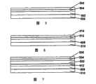
附图的图1是通过如上述2004/0027327所述的现有技术前平面叠层的剖面示意图,但释放层被除去以备层压至背平面.Figure 1 of the accompanying drawings is a schematic cross-sectional view through a prior art front plane laminate as described in 2004/0027327 above, but with the release layer removed for lamination to the back plane.
图2是表示现有技术显示器的剖面示意图,该显示器由将图1中所示的前平面叠层层压到含像素电极的背平面而产生.Figure 2 is a schematic cross-sectional view showing a prior art display produced by laminating the front plane stack shown in Figure 1 to a back plane containing pixel electrodes.
图3是通过本发明的前平面叠层的类似于图1的剖面示意图,此外释放层被除去以备层压至背平面.Figure 3 is a schematic cross-sectional view similar to Figure 1 through the front plane laminate of the present invention, except that the release layer has been removed for lamination to the back plane.
图4是表示显示器的类似于图2的剖面示意图,该显示器由将图1中所示的前平面叠层层压到含像素电极的背平面而产生.图5至9是示意侧视图,其表示在本发明的柔性子装配工艺中的各个步骤.Figure 4 is a schematic cross-sectional view similar to Figure 2 showing a display produced by laminating the front plane stack shown in Figure 1 to a back plane containing pixel electrodes. Figures 5 to 9 are schematic side views, which Represents each step in the flexible subassembly process of the present invention.
图10是本发明用于显示彩色图像的设备的示意侧视图.Figure 10 is a schematic side view of the device for displaying color images of the present invention.
图11是本发明用于产生不同颜色光脉冲的设备的示意侧视图.Figure 11 is a schematic side view of the device of the present invention for generating light pulses of different colors.
图12是通过可根据本发明制造的混合电泳显示器的显示单元的剖面示意图.图13A和13B是举例说明可用来减轻在如图12中所示显示器中的翘曲的方法的示意侧视图.Figure 12 is a schematic cross-sectional view of a display cell through a hybrid electrophoretic display that may be fabricated in accordance with the present invention. Figures 13A and 13B are schematic side views illustrating methods that may be used to mitigate warpage in a display such as that shown in Figure 12.
图14是表示可用来防止在如图12中所示显示器中的翘曲的进一步方法的示意侧视图.Figure 14 is a schematic side view showing a further method that can be used to prevent warping in the display shown in Figure 12.
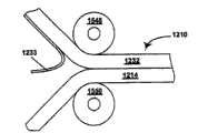
图15举例说明制造混合显示器的方法,其中温度调节用来控制任何显示器翘曲趋向.图16是同图12相比放大很多的剖面示意图,其表示一个可能的可用于图12显示器的边封形态.Figure 15 illustrates a method of fabricating a hybrid display in which temperature regulation is used to control any tendency of the display to warp. Figure 16 is a schematic cross-sectional view greatly enlarged compared to Figure 12, which shows a possible edge seal configuration that can be used for the display of Figure 12 .
如已指出,本发明具有数个不同的涉及电光显示器以及用于生产这种显示器的方法和器件的方面.这些不同的方面将主要在以下分别详细描述,但应当理解的是单个的显示器、方法或器件可使用本发明一个以上的方面.例如,使用本发明的前平面叠层可进行本发明制造混合显示器的不同方法.As already indicated, the present invention has several different aspects relating to electro-optic displays and methods and devices for producing such displays. These various aspects will mainly be described in detail below separately, but it should be understood that individual displays, methods Or devices can use more than one aspect of the invention. For example, different methods of making hybrid displays according to the invention can be performed using the front plane stackup of the invention.
无胶粘剂方法、介质、前平面叠层和双重释放薄膜Adhesive-free methods, media, front plane lamination and dual release films
本发明以上全部方面被结合在一起是因为它们都涉及排除通常用于封装的电泳介质和电泳显示器的至少一个其他器件之间的叠层胶粘剂;该其他器件典型地是背平面,但在某些情况下,本发明可使得剔除电泳介质和前基底之间的叠层胶粘剂,所述前基底提供观察表面,观察者通过其意图观看显示器.如已经提到的,剔除叠层胶粘剂是通过在电泳介质中使用粘合剂而进行的,所述粘合剂可在层压所用的温度条件下流动,因此实际上该粘合剂还作为叠层胶粘剂.流动的概念是复杂的但在本文中它是指一种聚合物材料,其已经通过从弹性到塑性或粘性状态的转变.All of the above aspects of the invention are brought together because they all involve the elimination of a lamination adhesive typically used in encapsulation between an electrophoretic medium and at least one other device of an electrophoretic display; typically the backplane, but in some In this case, the present invention allows removal of the lamination adhesive between the electrophoretic medium and the front substrate, which provides the viewing surface through which the viewer intends to view the display. As already mentioned, removal of the lamination adhesive is accomplished by This is done using an adhesive in a medium that can flow under the temperature conditions used for lamination, so in effect the adhesive also acts as a lamination adhesive. The concept of flow is complex but in this paper it Refers to a polymeric material that has passed through a transition from an elastic to a plastic or viscous state.
本发明用于无胶粘剂介质及方法的粘合剂的选择当然必须考虑的是不仅其流动温度而且其与另一个电泳介质器件的相容性以及驱动该介质的要求,特别包括粘合剂的电阻率.令人想望地,粘合剂在不超过150℃的温度下流动,并且优选在不超过100℃的温度下.通常,粘合剂的优选的类型是聚氨酯;已经发现某些聚氨酯可满足这些优选的流动温度而仍然可与通常用于电泳介质中的全部另一个器件相容.The choice of adhesive for use in the adhesive-free medium and method of the present invention must of course take into account not only its flow temperature but also its compatibility with another electrophoretic medium device and the requirements to drive the medium, including in particular the resistance of the adhesive Rate. Desirably, the adhesive flows at a temperature not exceeding 150°C, and preferably at a temperature not exceeding 100°C. In general, the preferred type of adhesive is polyurethane; certain polyurethanes have been found to satisfy These preferred flow temperatures are still compatible with all other devices commonly used in electrophoretic media.
此外,在选择用于本发明无胶粘剂介质及方法的粘合剂中,应该不仅注意所用粘合剂的类型而且应该注意粘合剂的比例.如在数个上述E Ink和MI T专利与申请中所讨论的,由将囊和粘合剂的混合物涂布到基底或聚合物-分散的类型的介质上所制备的封装的电泳介质往往具有非平面型表面,因为单独的囊或小滴在干燥和/或固化的电泳介质的表面上形成“凸起”,并且当(按照优选情况)介质基本上由囊或小滴的单个层组成时,情况更是如此.在使用叠层胶粘剂的常规方法中,叠层胶粘剂不仅用于将电泳介质粘附至背平面或其他器件,而且使电泳介质最初的非平面型表面平面化,因此避免各种的问题(例如,形成空穴和电泳介质对所施加的电场的不规则反应),如果将该电泳介质的非平面型表面层压至背平面或其他器件的平面型表面时,这些问题会另外出现.Furthermore, in selecting an adhesive for use in the adhesive-free medium and method of the present invention, attention should be paid not only to the type of adhesive used but also to the ratio of adhesive. As in several of the aforementioned E Ink and MIT patents and applications As discussed in , encapsulated electrophoretic media prepared by coating a mixture of capsules and binder onto substrates or polymer-dispersed types of media tend to have non-planar surfaces because individual capsules or droplets "Bumps" form on the surface of the dried and/or cured electrophoretic medium, and this is especially true when (as is preferred) the medium consists essentially of a single layer of capsules or droplets. In conventional lamination adhesives In this approach, the lamination adhesive is used not only to adhere the electrophoretic medium to the back plane or other device, but also to planarize the initially non-planar surface of the electrophoretic medium, thus avoiding various problems (e.g., formation of holes and pairing of the electrophoretic medium irregular response to an applied electric field), these problems additionally arise if the non-planar surface of the electrophoretic medium is laminated to a backplane or planar surface of other devices.
当根据本发明为避免这类问题而剔除叠层胶粘剂时,非常期望可流动的粘合剂不仅仅代替以前所用的叠层胶粘剂的胶粘剂功能,而且代替其平面化功能,并且为使可流动的粘合剂能够这样做,已经发现,与典型地现有技术所用的电泳介质(其意图与叠层胶粘剂一起使用)相比,通常期望使用在本发明无胶粘剂的电泳介质中更高比例的粘合剂.考虑,例如,一种理想化的封装的电泳介质,其包括依靠基底的六边形紧密填赛的球形囊的单个层.该囊占该层的体积分数是大约60.5%,该层的剩下的39.5vol%由粘合剂占据.这暗示囊与粘合剂体积比为约3∶2将足以使粘合剂能够填充囊间的所有空间,因此使囊层平面化.进一步考虑该理想化系统暗示粘合剂略大的比例(例如囊与粘合剂体积比为1∶1)是期望的,以保证过量粘合剂覆盖囊层,因此降低在层压过程期间囊壁可受损害和也许爆裂的机会.When lamination adhesives are eliminated in accordance with the present invention in order to avoid such problems, it is highly desirable that flowable adhesives not only replace the adhesive function of previously used lamination adhesives, but also their planarizing functions, and provide the necessary support for flowable adhesives. Adhesives are capable of doing this, and it has been found that it is generally desirable to use a higher proportion of adhesive in the adhesive-free electrophoretic media of the present invention than typically prior art electrophoretic media (which are intended for use with lamination adhesives). Mixture. Consider, for example, an idealized encapsulated electrophoretic medium comprising a single layer of hexagonally closely packed spherical capsules against a substrate. The volume fraction of the capsules is about 60.5% of the layer, and the layer The remaining 39.5 vol% of the volume is occupied by the adhesive. This implies that a capsule to adhesive volume ratio of about 3:2 would be sufficient to enable the adhesive to fill all the spaces between the capsules, thus planarizing the capsule layers. Considering further This idealized system implies that a slightly larger ratio of adhesive (e.g., a 1:1 bladder to adhesive volume ratio) is desirable to ensure that excess adhesive covers the bladder layer, thus reducing the risk of bladder wall stress during the lamination process. Chance of being damaged and maybe burst.
然而,如数个上述E Ink和MIT专利和申请所述(特别见美国专利Nos.6067185和6392785),实际上制造的封装的电泳介质与理想化模型有很大的差别,其中因为电泳介质层在干燥或固化期间收缩而使最初球形囊变平成扁椭球,以及在至少一些情况中,因为收缩继续,扁椭球彼此接触并且形成平面型接触区域,垂直于层的厚度充分延伸,因此最终囊具有基本上棱柱的形状,理想地六方柱.类似的效果随聚合物-分散的电泳介质而观察到.与紧密填赛的球形囊,扁椭球和棱柱形状的囊占电泳介质明显更大的比例,因此在前者情况中需要更少的粘合剂.另外,上述讨论集中在体积比,大多数粘合剂的密度往往略高于大多数电泳介质,所述电泳介质的多半是由低密度脂肪族烃悬浮液组成,因此粘合剂的重量比可略高于体积比.用于任何特定介质的粘合剂的最佳比例最好凭经验确定,但作为一般性指导可以说明的是聚合物粘合剂应该典型地占电泳介质的至少20%,令人想望地至少30wt%(该比值当然是基于实质上干燥的囊的重量和基于粘合剂固相物质(solid basis)计算的,因为粘合剂典型地作为一种胶乳被加入).典型地,最适比率将为2至3重量份的囊每重量份的聚合物粘合剂.应该避免使用大量过剩的粘合剂,因为这种过量往往“稀释”该囊,使其超过它们优良填赛的点,由此使介质的电光性能退化.However, as described in several of the aforementioned E Ink and MIT patents and applications (see especially U.S. Pat. Shrinkage during drying or curing flattens the initially spherical capsule into an oblate spheroid, and in at least some cases, as the shrinkage continues, the oblate spheroid contacts each other and forms a planar contact area, fully extending perpendicular to the thickness of the layer, so that the final Capsules have a substantially prismatic shape, ideally a hexagonal prism. Similar effects are observed with polymer-dispersed electrophoretic media. Oblate ellipsoidal and prismatic shaped capsules occupy significantly more electrophoretic media than tightly packed spherical capsules. ratio, so less binder is required in the former case. Also, the above discussion has focused on the volume ratio, most binders tend to be slightly denser than most electrophoretic media, which are mostly made of low density aliphatic hydrocarbon suspension composition, so the weight ratio of binder can be slightly higher than the volume ratio. The optimal ratio of binder for any particular medium is best determined empirically, but as a general guide it can be stated that The polymeric binder should typically comprise at least 20%, desirably at least 30% by weight of the electrophoretic medium (this ratio is of course based on the weight of the substantially dry capsule and calculated on the solid basis of the binder , because the binder is typically added as a latex). Typically, the optimum ratio will be 2 to 3 parts by weight of capsule per part by weight of polymeric binder. The use of large excesses of binder should be avoided, Because this excess tends to "dilute" the capsules beyond their point of good packing, thereby degrading the electro-optical properties of the medium.
本发明无胶粘剂方法的层压步骤可使用任何本领域已知的技术进行.因此,例如层压可使用卷对卷方法进行,使本发明前平面叠层(带有从其剥离的释放片层)和形成在柔性基底上的成卷背平面在层压机的受热辊间通过.The lamination step of the adhesive-free process of the present invention can be carried out using any technique known in the art. Thus, for example, lamination can be carried out using a roll-to-roll process with the front plane laminate of the present invention (with the release sheet peeled therefrom ) and the rolled back plane formed on the flexible substrate pass between the heated rollers of the laminator.
本发明的前平面叠层和双重释放薄膜可包括任何任选的描述于上述2004/0027327和2004/0155857中的特征.因此,例如,前平面叠层可具有导电通路和接触垫,如2004/0027327所述.前平面叠层的释放片层可具有导电层以便于以如上所述的方式检测前平面叠层.The front plane laminate and the dual release film of the present invention may include any of the optional features described in the aforementioned 2004/0027327 and 2004/0155857. Thus, for example, the front plane laminate may have conductive vias and contact pads as in 2004/0027327 and 2004/0155857. 0027327. The release sheet of the front plane stack may have a conductive layer to facilitate detection of the front plane stack in the manner described above.
本发明的前平面叠层不仅剔除现有技术FPL的层(即叠层胶粘剂层)而且简化总装配工艺.在描述于上述2004/0027327中的现有技术方法中,FPL典型地由将囊/粘合剂浆料涂布到基底上形成,所述基底包括含铟-锡-氧化物(ITO)层的聚合物薄膜,该淤浆被涂布到薄膜的ITO覆盖的表面上.所得的囊-涂布的薄膜然后经受第一层压,其中将叠层胶粘剂层层压到囊/粘合剂层的裸露表面,然后施加释放片层以形成FPL.当FPL将被装配成显示器时,该释放片层被除去并且进行第二层压以将叠层胶粘剂固定到背平面,因此形成最终显示器.本发明使能够使第一层压被剔除,因此简化生产显示器的总加工过程.The front plane lamination of the present invention not only eliminates the layers of the prior art FPL (i.e. the lamination adhesive layer) but also simplifies the general assembly process. In the prior art method described in the aforementioned 2004/0027327, the FPL is typically made of a pouch/ The adhesive slurry was coated onto a substrate comprising a polymer film comprising an indium-tin-oxide (ITO) layer, and the slurry was coated onto the ITO-covered surface of the film. The resulting capsules - The coated film is then subjected to a first lamination in which a laminate adhesive layer is laminated to the exposed surface of the pouch/adhesive layer and then a release sheet layer is applied to form the FPL. When the FPL will be assembled into a display, the The release sheet is removed and a second lamination is performed to secure the laminate adhesive to the back plane, thus forming the final display. The invention enables the elimination of the first lamination, thus simplifying the overall tooling to produce the display.
本发明的该方面现在将参考附图的图1-4进行举例说明.如已经提到的,图1表示如上述2004/0027327所述的现有技术的前平面叠层,但释放层被除去以备层压至背平面.如图1所示,前平面叠层包括前基底100,其由聚合物薄膜形成,含铟氧氧化物的层102(层102的厚度与基底100的厚度相比被大大地放大,便于说明),其将形成最终显示器的公共前电极.前平面叠层进一步包括电泳层,其包括在粘合剂106中的囊104,和叠层胶粘剂层108.This aspect of the invention will now be illustrated with reference to Figures 1-4 of the accompanying drawings. As already mentioned, Figure 1 shows a prior art front plane stack as described in 2004/0027327 above, but with the release layer removed In preparation for lamination to the backplane. As shown in FIG. 1, the frontplane laminate comprises a
图2表示由将图1的前平面叠层层压到含像素电极(未示)的背平面110而产生的结构.将会看到,在图2的叠层中,两个电泳层104/106和胶粘剂层108存在于平面电极层102和像素电极之间.Figure 2 shows the structure resulting from laminating the front plane stack of Figure 1 to a
图3表示本发明的前平面叠层,此外释放层被除去以备层压至背平面.图3的前平面叠层通常类似于图1的前平面叠层,但具有热可流动的粘合剂106′而没有胶粘剂层.Figure 3 shows the front plane laminate of the present invention with the release layer removed in preparation for lamination to the back plane. The front plane laminate of Figure 3 is generally similar to that of Figure 1 but with a heat flowable bond agent 106' without adhesive layer.
最后,图4表示由图3的前平面叠层层压到背平面110而产生的结构.将会看到,在图4的叠层中,在前平面电极层102和像素电极之间仅仅存在电泳层104/106.因为消除电极之间的胶粘剂层,在任何给定的工作电压条件下,图4的叠层将典型地比图2的叠层基本上转换得更快.现在给出以下实施例,然而只作为说明,以举例说明本发明的优选实施方案.Finally, Figure 4 shows the structure resulting from the lamination of the front plane stack of Figure 3 to the
实施例Example
基本上如上述2002/0185378的实施例30所述,制备在脂肪族烃悬浮液中含聚合物-涂布的二氧化钛和炭黑粒子的以及具有凝胶/阿拉伯树胶囊壁的双粒子相反极性电泳囊.这些囊然后与常规聚氨酯胶乳粘合剂以1∶1重量比(囊/粘合剂固相物质)混合,基本上如该实施例30所述,将所得物缝式涂布到5mil(127μm)聚(对苯二甲酸乙二酯)(PET)薄膜(该薄膜在一个表面上涂布有ITO)上,并固化以产生最终的囊/粘合剂层,其基本上包括囊的单层并且厚度为15-30μm.所得的囊-涂布的薄膜基本上是本发明的FPL,除了它没有释放片层以外,所述释放片层不是必需的,因为涂布的薄膜紧接着被使用,如下所述.Biparticles of opposite polarity containing polymer-coated titanium dioxide and carbon black particles in an aliphatic hydrocarbon suspension and having gel/arabic capsule walls were prepared essentially as described in Example 30 of the above-mentioned 2002/0185378. Electrophoretic capsules. These capsules were then mixed with a conventional polyurethane latex adhesive in a 1:1 weight ratio (capsules/adhesive solid phase) essentially as described in this Example 30, and the resultant was slot coated to 5 mil (127 μm) poly(ethylene terephthalate) (PET) film (which is coated with ITO on one surface) and cured to produce the final capsule/adhesive layer, which essentially comprises the Single layer and thickness of 15-30 μm. The resulting capsule-coated film is essentially the FPL of the present invention, except that it has no release sheet, which is not necessary because the coated film is then use, as described below.
使用热辊层压机,然后将囊涂布的薄膜层压到包括覆盖石墨层的聚合物薄膜的背平面,电泳层和石墨层接触,以及将所得的结构切成2英寸正方形(51mm正方形)的尺寸以产生试验性单象素显示器,其显现令人满意的电光性能.Using a heated roll laminator, the pouch-coated film was then laminated to the back plane of the polymer film comprising the graphite layer covering the electrophoretic layer and the graphite layer in contact, and the resulting structure was cut into 2 inch squares (51 mm squares) size to produce an experimental single-pixel display that exhibits satisfactory electro-optic performance.
进一步相似的实验表明以较低的粘合剂与囊重量比约1∶2-1∶3,能够获得令人满意的电光性能.Further similar experiments showed that satisfactory electro-optic performance could be obtained with a lower binder to capsule weight ratio of about 1:2–1:3.
柔性子装配方法Flexible Subassembly Method
本发明的柔性子装配方法使得装配极柔性和顺性显示器以良好地适用于例如上述其中柔性是最重要因素的应用.A优选的子装配方法将参考附图的图5-9进行描述.The flexible subassembly method of the present invention enables the assembly of extremely flexible and conformable displays well suited for applications such as those described above where flexibility is the most important factor. A preferred subassembly method will be described with reference to Figures 5-9 of the accompanying drawings.
优选的方法以第一释放片层500(图5)为起点.电光介质502层被涂布或另外被沉积在第一释放片层500上.分别地,叠层胶粘剂504层形成在第二释放片层506上并且被层压至电光介质502,使得叠层胶粘剂504粘附于电光介质502.The preferred method starts with a first release sheet layer 500 (FIG. 5). A layer of electro-
在另外的操作中,如图6所示,背平面508通过丝网印刷或类似的淀积方法(见上述E Ink/MIT专利和申请,用于形成这种背平面的适当的方法)在第三释放片层510上形成.分别地,叠层胶粘剂512层形成在第四释放片层514上并且被层压到背平面508,使得叠层胶粘剂512粘附于背平面508.In another operation, as shown in FIG. 6, the
在本方法的下一步中,使第四释放片层514从图6所示的结构除去,因此使叠层胶粘剂512暴露,并且使第一薄板500从图5所示的结构除去,因此使电光介质502暴露.然后两个所得的结构用和电光介质502接触的叠层胶粘剂512层压在一起,因此形成图7所示的多层结构.In the next step of the method, the fourth
在另外的操作中,另一个叠层胶粘剂516层被涂布在第五释放片层518上.第三释放片层510从图7所示的结构中撕去并且叠层胶粘剂516和第五释放片层518被层压至其背平面表面以产生图8所示的结构.In a further operation, another layer of
该方法的下一步将图8的结构固定至基底,例如压力感应开关或传感装置,其已经覆盖了绝缘材料薄层以使图8结构的电光显示器器件绝缘.此叠层通过从图8结构剥落第五释放片层518并且将叠层胶粘剂516层压因而暴露于基底520(图9)而起作用.或者,此叠层胶粘剂层(其与传感或开关装置接触)可由高绝缘压敏粘结剂材料形成,而在这样情况下可以剔除绝缘材料层.最后,去除第二释放片层506以使叠层胶粘剂504暴露,然后将叠层胶粘剂504层压至顶端平面电极522,顶端平面电极522将典型地支承在前基底如聚合物薄膜(其用作保护层以保护最终的电光显示器)上.或者,顶端平面电极522可通过涂布过程形成,例如通过将导电聚合物沉积在叠层胶粘剂504上.The next step in the process is to secure the structure of Figure 8 to a substrate, such as a pressure sensitive switch or sensing device, which has been covered with a thin layer of insulating material to insulate the electro-optic display device of the Figure 8 structure. The fifth
遵循相同的基本构图可使用不同的替代方法.例如,电光介质在本方法的第一步骤中可直接涂布在导电支承上,由此完全省去第二释放片层的除去和顶端平面电极的层压或形成.此过程导致类似于图9结构的结构,但没有最顶端的叠层胶粘剂层.或者,不剥落第一释放片层以使电光介质暴露,而可将第二释放片层剥落以得到具有暴露的胶粘剂层的双层涂层.然后可将此双层涂层层压至薄的塑性支承上的导电层.就此,第一释放片层可被除去而该方法的最后一步如前所述进行.还会设想到其他装配变化,因此可使用一般方法以多种方式构造多种不同的电光显示器结构和装置.Different alternative methods can be used following the same basic pattern. For example, the electro-optic medium can be coated directly on the conductive support in the first step of the method, thereby completely omitting the removal of the second release sheet layer and the removal of the top planar electrode. lamination or forming. This process results in a structure similar to the Figure 9 structure, but without the topmost laminated adhesive layer. Alternatively, instead of peeling off the first release sheet to expose the electro-optic medium, the second release sheet can be peeled off To obtain a double-layer coating with an exposed adhesive layer. This double-layer coating can then be laminated to a conductive layer on a thin plastic support. At this point, the first release sheet layer can be removed and the final step of the process is as The foregoing is carried out. Other assembly variations are also contemplated so that a variety of different electro-optic display structures and devices can be constructed in a variety of ways using the general approach.
这里所举例说明的构造技术特别地提供至少两个新型结构的制备,所述结构包括直接粘附于机械传感器的电光显示器装置.该两个新型结构的区别是,其中一个,显示设备的顶端受保护性薄板(典型地塑料薄膜)的保护,而第二个(其中顶端平面电极用作导电聚合物材料,如PEDOT)没有进一步的保护层.优选的结构取决于应用和所需装置的耐用性.在机械传感器通过按钮激活的情况下,与电光装置表面接触的按钮面应被制成平滑的和/或略柔顺的,因此,可不需要保护性塑性层.如果传感器的驱动是通过使用手指或触笔或其他锋利物体而发生(如在触屏应用中),为了耐用性,将可能需要顶端保护层.但不论是哪种情况,装置的耐用性将得到改进,如果电光介质是聚合物分散的电泳介质的话.The construction techniques exemplified here provide, inter alia, the fabrication of at least two novel structures comprising electro-optic display devices directly attached to mechanical sensors. The difference between these two novel structures is that in one, the top end of the display device is controlled by The protection of a protective thin plate (typically a plastic film), while the second (where the top planar electrode is used as a conductive polymer material such as PEDOT) has no further protective layer. The preferred structure depends on the application and the durability of the device required . In the case of a mechanical sensor activated by a button, the surface of the button in contact with the surface of the electro-optical device should be made smooth and/or slightly compliant, so that a protective plastic layer may not be required. If the sensor is actuated by using a finger or stylus or other sharp objects (such as in touch screen applications), for durability, will likely need a top protective layer. But in either case, the durability of the device will be improved, if the electro-optic medium is polymer dispersed the electrophoretic medium.
也可以使用其它施用电光介质的方法.特别地,将电泳囊和粘合剂电淀积到图案化的背平面(见,国际申请PCT/US2004/009421)将是特别适合结合电光介质的方法,并且将剔除上述过程中的一些层压/脱层步骤.本技术还将能够使用除了黑色或白色以外的多个专色来增强显示功能.Other methods of applying electro-optic media may also be used. In particular, electrodeposition of electrophoretic capsules and adhesives onto a patterned back plane (see, International Application PCT/US2004/009421) would be a particularly suitable method for incorporating electro-optic media, And will eliminate some of the lamination/delamination steps in the above process. This technology will also be able to use multiple spot colors other than black or white to enhance the display function.
由上述可知本发明的柔性子装配方法可提供直接耦合到机械传感器的电光显示器和使用一系列层压步骤来装配这种装置的一般方法.显示器和传感器之间的直接耦合剔除了对至少一个相对刚性的支承薄板的需要,改进该耦合装置的分辨率和触觉.一个可由本发明实现的这种装置是使用封装的电泳显示器的触屏;另一个是具有可转换按钮指示器的电话机键区.这是极强大的构造技术的一种用途,所述构造技术可利用封装的电泳介质的耐用性和柔性.From the foregoing it follows that the flexible subassembly method of the present invention provides electro-optic displays coupled directly to mechanical sensors and a general method of assembling such devices using a series of lamination steps. The direct coupling between the display and the sensor eliminates the need for at least one relative The need for a rigid support sheet improves the resolution and haptics of the coupling device. One such device that can be realized by the present invention is a touch screen using an encapsulated electrophoretic display; another is a telephone keypad with switchable button indicators .This is one use of an extremely powerful construction technique that exploits the durability and flexibility of encapsulated electrophoretic media.
用于显示彩色图像和产生光脉冲的设备Devices for displaying color images and generating pulses of light
如已经提到的,本发明提供用于显示彩色图像的设备,和用于产生不同颜色光脉冲的设备,后一设备意图用作显示彩色图像设备中的子配件.As already mentioned, the invention provides a device for displaying color images, and a device for generating light pulses of different colors, the latter device being intended for use as a subassembly in a device for displaying color images.
如上所述,已经举例说明封装的电泳介质和相似的电光介质适合滤色阵列.然而,存在着数个与使滤色阵列、电泳介质或其他电光介质和电子驱动器整合有关的根本挑战.与这种显示器设计有关的关键问题涉及利用子象素以形成显示器的像素.在此结构中,子象素(例如红R、绿G和蓝B)必须被各个寻址以便欺骗人眼使其看见基本颜色的光谱.换句话说、最小的可寻址元件只显示单个颜色和其色调,即子象素不能显示可见光的全部光谱.在优选实施方案中,该显示器的最小的可寻址元件可显示每个基本色(我们实施例中的R、G和B).本发明的设备使用百叶窗方式的电光介质和场序制操作技术(即,一种技术,其中表现总图像各个彩色通道的“子图像”在时间上而不是空间上分离,但分离是以观察者眼睛看见总的彩色图像的方式进行)解决了此问题.As noted above, encapsulated electrophoretic media and similar electro-optic media have been exemplified as suitable for color filter arrays. However, there are several fundamental challenges associated with integrating color filter arrays, electrophoretic media, or other electro-optic media, and electronic actuators. Related to this A key issue with this display design involves the use of sub-pixels to form the pixels of the display. In this structure, the sub-pixels (such as red R, green G, and blue B) must be individually addressed in order to trick the human eye into seeing basic Spectrum of colors. In other words, the smallest addressable element displays only a single color and its hue, i.e. the subpixel cannot display the full spectrum of visible light. In a preferred embodiment, the smallest addressable element of the display can display Each of the primary colors (R, G, and B in our embodiment). The device of the present invention uses a louver-like electro-optic medium and a field-sequential operating technique (i.e., a technique in which "sub-colors" representing the individual color channels of the total image images" are separated in time rather than in space, but the separation is in such a way that the observer's eyes see the total color image) solves this problem.
存在两种使用场序制寻址的方法而剔除如上所述的问题.第一,使用本发明用于显示彩色图像的设备,在显示器中可使用色序背光器(backlight)(例如,由LumiLEDs Corporation,San Jose,CA制造的背光器),并且使用“快门模式”的电光光学传感器.场序制背光器周期性地、与光学传感器的快门速度同步地闪过显示器的基本色,如红、绿和蓝.通过用适当的时空控制方法使光学传感器从明晰到不透明转换,全色图象可呈现给观察者.这类装置在附图的图10中以非常示意的方式举例说明.图10显示一种电光显示器,其包括含多个像素电极(未示)的基底1000、电光介质(例如封装的电泳介质)的层1002和连续的前电极1004.该显示器具有场序制背光器1006,其闪烁红、绿和蓝,其与电光介质层1002的快门速度同步.该传感器和背光器应该足够迅速转换以使得人眼在时间上整合显示器所发出的颜色.There are two methods of using field sequential addressing to eliminate the problems described above. First, using the device of the present invention for displaying color images, color sequential backlights (e.g., made of LumiLEDs) can be used in the display. Corporation, San Jose, CA), and uses a "shutter mode" electro-optic optical sensor. The field sequential backlight flashes the primary colors of the display, such as red, Green and blue. By switching the optical sensor from clear to opaque with appropriate spatiotemporal control methods, a full-color image can be presented to the observer. Such a device is illustrated in a very schematic manner in Figure 10 of the accompanying drawings. Figure 10 An electro-optic display is shown comprising a
其次,使用堆叠的电光薄膜,可以构造色序背光器(即,用于产生不同颜色光脉冲的本发明的设备).这些堆叠的电光薄膜,其意图与“单色”调光器(其可为如图10所示的电光类型)一起使用,仅需要连续电极,因此它们将具有低生产成本.这类装置在附图的图11中以非常示意的方式举例说明.图11显示了堆叠的色序后反射器,其包括具有连续电极1102和1104的蓝色快门模式的电光介质层1100(例如,封装的电泳介质)、具有连续电极1108和1110的绿色快门模式的电光介质层1106和具有连续电极1114和1116的红色快门模式的电光介质层1112.(对本领域技术人员将显而易见的是,通过提供能够产生多个驱动电压的电压电源,相邻电极对1104/1108和1110/1114中的每一个可以被剔除.)在如图11所示的全色光学传感器中,电光介质薄膜应该被堆叠以最优化其性能.例如,如果用于该薄膜的透明导体是对部分可见光谱具有特别的吸收性,那么那个颜色应该在堆叠层中比其余呈现更高的彩度.快门模式光学传感器,或任何其他光学传感器(液晶、悬浮粒子显示器、胆甾醇型液晶、双稳态向列型液晶等)可与该设备一起使用作为单色光学传感器.Second, using stacked electro-optic films, it is possible to construct color-sequential backlights (i.e., devices of the invention for generating light pulses of different colors). For use with the electro-optic type as shown in Figure 10), only continuous electrodes are required, so they will have low production costs. Such devices are illustrated in a very schematic way in Figure 11 of the accompanying drawings. Figure 11 shows the stacked A color sequential rear reflector comprising a blue shutter mode electro-optic medium layer 1100 (e.g., encapsulated electrophoretic medium) with
尽管图11举例说明使用三个堆叠的薄膜,其是最普通的配置(红色/绿色/蓝色或者黄色/青色/洋红色),本发明不局限于使用该三个堆叠的薄膜;在某些情况下,通过仔细选择色彩范围,只使用两个堆叠的薄膜,也许可能产生有益的彩色图像,或者使用更多个堆叠的薄膜来改进最终图像的色域.同样地,在用于显示彩色图像的本发明的设备中,发光装置将典型地被安排闪烁三个不同的颜色的单独的脉冲,但可使用较小或较大数目的颜色.Although FIG. 11 illustrates the use of three stacked films, which are the most common configurations (red/green/blue or yellow/cyan/magenta), the invention is not limited to the use of three stacked films; In some cases, by carefully selecting the color range, it may be possible to produce beneficial color images by using only two stacked films, or by using more stacked films to improve the color gamut of the final image. Similarly, when used to display color images In a device of the invention, the light emitting means will typically be arranged to flash in separate pulses of three different colours, but a smaller or greater number of colors may be used.
本发明的这个方面能够使用快门模式电光介质特别是封装的电泳介质来制造全色显示器.图10中所示类型的设备使得具有非常高的色饱和度和亮度,因为色序LED背光器提供了可观的色域性能和光输出.图11所示类型的堆叠的电泳快门模式的背面设备对于产生光脉冲的设备而言是低功率、潜在低成本的设计.This aspect of the invention enables the fabrication of full-color displays using shutter-mode electro-optic media, particularly encapsulated electrophoretic media. Devices of the type shown in Figure 10 enable very high color saturation and brightness because the color-sequential LED backlight provides Appreciable color gamut performance and light output. A stacked electrophoretic shutter-mode backside device of the type shown in Figure 11 is a low-power, potentially low-cost design for a device that generates light pulses.
形成电光显示器的方法和器件Method and device for forming an electro-optic display
如已经提到的,在将FPL′s层压至玻璃有源基质背平面(通常携带薄膜晶体管阵列,或缩写TFT′s)的方法研制期间,遇到许多问题与传统层压设备有关的问题.本发明提供所需的和期望的常规工具的变型,以便于在玻璃TFT′s上层压FPL′s.这些变型也可用于设计层压工具,其用于使用塑料或金属箔背平面的FPL型显示器.变型可适宜分为三个主要领域,即叠层的温度控制、相对于背平面的FPL的堆放和进行层压的工作台的设计,这三个领域在下面分别论述.As already mentioned, during the development of the method for laminating FPL's to the backplane of a glass active substrate (often carrying arrays of thin-film transistors, or abbreviated TFT's), many problems were encountered in relation to conventional lamination equipment . The present invention provides required and desired variations of conventional tools to facilitate lamination of FPL's on glass TFT's. These variations can also be used to design lamination tools for FPLs using plastic or metal foil backplanes The variants can be suitably divided into three main areas, temperature control of the stack, stacking of the FPL relative to the back plane, and design of the workbench where the lamination is performed, which are discussed separately below.
叠层的温度控制Stack temperature control
可用于液晶显示器(LCD)制造的常规的起偏器层压机基本上适用于将FPL′s层压到背平面,条件是该常规机器被改进以包括用于加热待层压的零件的系统.在加热待层压的零件中存在着优选的方法,然而,一些非容易地显而易见.Conventional polarizer lamination machines available for liquid crystal display (LCD) manufacture are essentially suitable for laminating FPL's to the back plane, provided that the conventional machine is modified to include a system for heating the parts to be laminated .There are preferred methods in heating the parts to be laminated, however, some are not readily apparent.
最期望的是以这样的方式施加热,将叠层粘合温度升高以足以引起叠层胶粘剂(其典型地是聚氨酯)中的塑性流动.存在许多可用来描述塑性流动的量度标准,其对于本领域技术人员是众所周知的.为了本目的,可以说明的是粘合层温度应该等于或高于叠层胶粘剂的体积和剪切模量相等时的温度(下文称作交点).可简单地通过以下方法实现这个温度水平,将该背平面加热到比该交点高很多的温度并且在压力(通过未受热的辊或芯轴所施加的)条件下涂覆该FPL.It is most desirable to apply heat in such a way that the laminate bonding temperature is raised sufficiently to induce plastic flow in the laminate adhesive (which is typically polyurethane). There are many metrics that can be used to describe plastic flow, which are useful for It is well known to those skilled in the art. For this purpose, it can be stated that the bonding line temperature should be equal to or higher than the temperature at which the volume and shear modulus of the laminate adhesive are equal (hereinafter referred to as the intersection point). This can be achieved simply by This temperature level is achieved by heating the backplane to a temperature much higher than the intersection point and coating the FPL under pressure (applied by an unheated roll or mandrel).
在改进的方法中,还可以加热该辊或芯轴,使得可以实现粘合层温度的更精细的控制.在另一种变化中,辊、背平面和FPL本身可被加热以进行更高度的控制.在这最后的变化中,FPL的预热使得处理量得到明显的改进,因为在进入发生层压的区域前,该胶粘剂被预软化.在所有实施方案中,导热板(铜、铝等)可用来提高所选择的加热元件的热均匀性.In a modified approach, the roll or mandrel can also be heated so that finer control of the bondline temperature can be achieved. In another variation, the roll, back plane and FPL itself can be heated for a higher degree of Control. In this last variation, the preheating of the FPL results in a marked improvement in throughput because the adhesive is pre-softened before entering the area where lamination occurs. In all embodiments, the thermally conductive plate (copper, aluminum, etc. ) can be used to improve the thermal uniformity of the selected heating element.
堆放控制用于LCD工业的传统的起偏器层压机可将塑料薄膜极精确地(±0.2mm-±0.3mm堆放精确度对于最新技术机器是寻常的)置于玻璃衬底上.当考虑FPL′s的热叠层时,然而,人们发现叠层温度不能如此高以使得FPL往往在层压过程期间滑动.存在四个影响FPL滑动的主要参数:Stacking Control Conventional polarizer laminators for the LCD industry can place plastic films on glass substrates with extreme precision (±0.2mm-±0.3mm stacking accuracy is common for state-of-the-art machines). When considering When thermally laminating FPL's, however, it has been found that the lamination temperature cannot be so high that the FPL tends to slip during the lamination process. There are four main parameters that affect FPL slip:
1.叠层胶粘剂材料的选择;1. Selection of laminated adhesive materials;
2.叠层胶粘剂厚度;2. Lamination adhesive thickness;
3.叠层温度,和3. Stack temperature, and
4.在层压期间施加于FPL上的力。4. Forces exerted on the FPL during lamination.
例如,对于当前优选的聚氨酯叠层胶粘剂在FPL中以18μm厚使用来说,有必要将玻璃背平面控制在温度小于85℃以防止在层压过程中FPL在玻璃上的明显滑动(假设层压过程中在FPL上的正常张力和使用未受热的辊).对于15μm厚的胶粘剂,温度小于95℃,滑动是可接受的(对于该过程中在FPL上的正常张力).因此,上述四个参数应该被控制以免在层压过程中FPL的明显滑动.期望滑动小于1mm,更令人想望地小于0.5mm,和最令人想望地小于0.3mm.For example, for the currently preferred polyurethane lamination adhesive to be used in FPL at 18 μm thick, it is necessary to control the glass backplane temperature to less than 85°C to prevent significant sliding of the FPL on the glass during lamination (assuming lamination normal tension on the FPL during the process and use of unheated rollers). For 15μm thick adhesives at temperatures less than 95°C, slippage is acceptable (for normal tension on the FPL during the process). Therefore, the above four The parameters should be controlled to avoid significant slippage of the FPL during lamination. Slippage of less than 1mm is desired, more desirably less than 0.5mm, and most desirably less than 0.3mm.
工作台设计workbench design
就FPL层压工具而言,本发明提供两个FPL支承工作台的改进.第一个改进是支承工作台的热控制.该温度控制使能够预热FPL及由此的FPL上的胶粘剂,使得大大地增加层压速度.加热可通过传导、对流或辐射加热完成.FPL的加热当然不应该如此强烈以至于损害FPL.As far as FPL lamination tools are concerned, the present invention provides two improvements to the FPL support table. The first improvement is the thermal control of the support table. This temperature control enables preheating of the FPL and thus the adhesive on the FPL such that Greatly increases lamination speed. Heating can be done by conduction, convection or radiant heating. The heating of the FPL should of course not be so intense that it damages the FPL.
其次,工作台应该平滑,以至其不刮伤FPL的塑料表面.工作台可用聚四氟乙烯(例如“TEFLON”,注册商标,其售自E.I.du Pont deNemours &Co.,Wilmington,Delaware,美国)或一些相似的柔软、非刮伤塑料材料涂布或构成.或者,工作台可由金属构成,并且用非刮伤表面涂布或阳极化.多孔石真空工作台是可用的,但这些工作台可增加工具刮伤FPL的倾向.Second, the table should be smooth so that it does not scratch the plastic surface of the FPL. The table can be polytetrafluoroethylene (such as "TEFLON", registered trademark, which is sold by E.I. du Pont deNemours & Co., Wilmington, Delaware, USA) or Coated or constructed of some similar soft, non-scratching plastic material. Alternatively, the table can be constructed of metal and coated or anodized with a non-scratching surface. Porous stone vacuum tables are available, but these can be increased Tendency of tool to scratch FPL.
本发明还提供以下的对于将FPL层压到背平面的进一步改进:The present invention also provides the following further improvements for laminating the FPL to the backplane:
提供容易调节辊所接触FPL的起始位置的能力.提供容易调节辊落下到FPL的起始位置的能力.(在常规LCD型设备中,辊总是在薄膜的边缘落下,这对于FPL层压是不合需要的.对这种机器的简单调整使能够改变FPL的起始位置和长度,而不是辊的起始位置;提供这种调整是期望的.)Provides the ability to easily adjust the starting position of the FPL where the roll touches. Provides the ability to easily adjust the starting position where the roll falls to the FPL. (In conventional LCD-type equipment, the roll always falls at the edge of the film, which is critical for FPL lamination is undesirable. A simple adjustment to such a machine enables changing the starting position and length of the FPL, but not the starting position of the roll; providing such an adjustment is desirable.)
提供加热滚筒以产生更好的温度均匀性和控制,剔除在运行期间叠层粘合层温度漂移的可能性.Heated rollers are provided for better temperature uniformity and control, eliminating the possibility of laminate bondline temperature drift during operation.
各种薄膜工作台的变型,包括设置真空孔以最佳匹配FPL的成品形状;加热工作台(其可对确保均匀的叠层温度具有次要的影响,尽管对辊加热是更重要的);在工作台上提供平整表面以使FPL的刮伤最小化.Variations of various film stages, including setting vacuum holes to best match the finished shape of the FPL; heated stages (which may have a minor impact on ensuring uniform lamination temperature, although roller heating is more important); Provide a flat surface on the bench to minimize scratching of the FPL.
制造混合显示器Manufacturing Hybrid Displays
如已经提到的,本发明提供数个制造混合显示器的方法.本发明这个方面涉及设计方法学,其能够制造混合显示器,即使用由异质材料组成的前后表面所构造的显示器.本发明这个方面适用于各种类型的电光显示器.As already mentioned, the present invention provides several methods of fabricating hybrid displays. This aspect of the invention relates to design methodologies that enable the fabrication of hybrid displays, that is, displays constructed with front and rear surfaces composed of heterogeneous materials. This aspect of the invention Aspects are applicable to various types of electro-optic displays.
如已指出,制造混合显示器是极复杂的,因为出现几乎在传统的显示器单元制造中不存在的问题.本发明提供用于制造混合显示器的方法和装置并且包括以下:As already pointed out, manufacturing a hybrid display is extremely complex because problems arise that are almost non-existent in the manufacture of conventional display units. The present invention provides a method and apparatus for manufacturing a hybrid display and includes the following:
1.常注意由CTE和CHE不匹配产生的面板曲率和使用应力释放或降低方法和装置以修正曲率;1. Always pay attention to the panel curvature caused by the mismatch between CTE and CHE and use stress relief or reduction methods and devices to correct the curvature;
2.谨慎地控制在制造过程中的环境条件;和/或2. Careful control of environmental conditions during the manufacturing process; and/or
3.产生一种平衡的零应力曲率,其匹配产品机壳或结构所需的曲率.3. Produce a balanced zero-stress curvature that matches the curvature required by the product enclosure or structure.
在本发明一个实施方案中,弯曲降低方法包括蠕变机理.加热混合显示器到阈值以上的温度.然后面板温度逐渐地降低,在某些情况下经过较长的时间,以释放由该显示器面板间的不均匀膨胀产生的结构应力.In one embodiment of the invention, the warp reduction method involves a creep mechanism. The hybrid display is heated to a temperature above a threshold. The panel temperature is then gradually lowered, in some cases over an extended period of time, to release the Structural stresses caused by non-uniform expansion.
在另一个实施方案中,弯曲降低方法通过强制显示器暂时呈现相反的曲率并且使显示器“弹”回而降低混合显示器的曲率.例如,显示器可被压在重物和弯曲表面之间以强制补偿其先天曲率.In another embodiment, the curvature reduction method reduces the curvature of a hybrid display by forcing the display to temporarily assume the opposite curvature and causing the display to "spring" back. For example, a display may be pressed between a weight and a curved surface to force compensation for its curvature. innate curvature.
在进一步的实施方案中,将第三层粘附于后面板的背面以补偿面板叠层和后面板之间的物理差异,其否则将导致更大的曲率度.在许多以下物理性能中,额外的第三层可不同于后面板:CTE、CHE、杨氏模量和厚度.In a further embodiment, a third layer is adhered to the back of the rear panel to compensate for physical differences between the panel stackup and the rear panel that would otherwise result in a greater degree of curvature. Among many of the following physical properties, additional The third layer can be different from the back panel: CTE, CHE, Young's modulus and thickness.
在又一个实施方案中,调节面板叠层和后面板至不同温度使得当它们被粘附以形成混合显示器时,曲率降低(如果没有剔除的话).面板中至少一个可为辊所移动的卷材.In yet another embodiment, the panel stack and back panel are adjusted to different temperatures such that when they are adhered to form a hybrid display, the curvature is reduced (if not rejected). At least one of the panels may be a web moved by a roller .
根据本发明的这个方面,还改进制造过程的其他方面以降低显示器曲率的风险,例如,在封边过程和结构化过程中.According to this aspect of the invention, other aspects of the manufacturing process are also improved to reduce the risk of display curvature, for example, during the edge banding process and the structuring process.
图12举例说明上述2004/0027327的图20所示类型的和使用FPL工艺所制造的电泳显示器单元(通常指定1210).显示器单元1210可为柔性的,即,可弯的或可辊的而无永久变形.在这个构造中,显示器1210的前平面1212是塑性的并且背平面1214由玻璃形成而且具有TFT阵列.可能在前平面1212上存在进一步的保护层1215.该保护层1215可为抗紫外线的保护层或抗氧气或湿气进入显示器1210的隔离物.或者,保护层1215可提供额外的耐冲击性或可提高某些光学效果,例如,具有抗反射涂层.Figure 12 illustrates an electrophoretic display unit (commonly designated 1210) of the type shown in Figure 20 of the aforementioned 2004/0027327 and fabricated using the FPL process. The
电泳介质层1216位于前平面1212和背平面1214之间.电泳层1216可包括一个或多个在粘合剂1220中的囊1218(为了清楚,从图12省略掉电泳粒子).导电层1222用作显示器1210的公共前电极,并且被置于前平面1212和电泳层1216之间.在一个实施方案中,导电层1222包括薄的透光导电材料,例如,ITO、氧化铝,或导电聚合物.示意地显示电路板1224,其与背平面1214连接,用于寻址电泳层1216以及导电层1222.
胶粘剂层1226可被置于电泳层1216和背平面1214之间.可能在显示器1210中存在进一步的层和零件用于各种的功能,例如,阻挡膜(进一步防止外部污染物如水分)、接触垫(用于检测寻址电泳层1216)、助胶粘剂层等.部分的那些实施方案更详细地描述于上述2004/0027327和2004/0155857中.密封1230可围绕一个或多个显示器1210的边.在一个实施方案中,如已经描述过的,在前平面1212和胶粘剂层1226之间的并且包括前平面1212和胶粘剂层1226的层首先作为FPL 1232制造其随后被层压至背平面1214.保护层1215可认为是部分FPL,如果在FPL被层压至背平面1214之前其附着于前平面1212.在说明中为简单起见,在附图中所示的FPL 1232包括保护层1215.当完成FPL 1232的制造时,释放片层(未示)临时附着于相对电泳层1216的胶粘剂层1226.在将FPL 1232层压至背平面1214前,除去释放片层.
可用于制造前平面1212和/或保护层15的材料的实例包括热稳定的聚(对苯二甲酸乙二酯)(例如,Melinex级504,来自Dupont TeijinFilms,Wilmington,Delaware,美国)和高性能硅酸硼玻璃(1737,来自Corning Incorporated,Corning,New York,美国).在其他实施方案中,PET薄膜可被聚萘二甲酸乙二醇酯(PEN)、聚醚砜(PES)代替,或在不超出本发明的范围的条件下,其他光学上透明或近透明的薄膜可被构造.Examples of materials that can be used to make the
在不超出本发明范围的条件下,类似于图1所示的其他显示器单元结构可被构造.其他实施方案包括封装的电泳和相似的电光显示器单元,其使用:Other display cell structures similar to those shown in Figure 1 can be constructed without exceeding the scope of the invention. Other embodiments include encapsulated electrophoretic and similar electro-optic display cells using:
1.金属箔背平面,其表面包含一个或多个有源的或无源的电子电路或装置,1. Metal foil back planes, the surface of which contains one or more active or passive electronic circuits or devices,
2.塑料薄膜背平面,其表面包含一个或多个有源的或无源的电子电路或装置,2. Plastic film back plane, the surface of which contains one or more active or passive electronic circuits or devices,
3.FPL,其包括在电泳介质和显示器的观察器间表面上的刚性或柔性的滤色阵列,或3. FPL comprising a rigid or flexible color filter array on the surface between the electrophoretic medium and the viewer of the display, or
4.塑料或玻璃衬底,具有有源的或无源的电子电路或装置和滤色阵列(无论在哪种情况下,前平面叠层有效地变成背平面叠层).4. Plastic or glass substrates with active or passive electronic circuits or devices and color filter arrays (in either case the front plane stack effectively becomes the back plane stack).
电子显示器设计和集成领域的技术人员可容易地识别其他显示器结构,其中本发明的原理在不超出本发明范围的条件下可被应用.Those skilled in the art of electronic display design and integration will readily recognize other display structures in which the principles of the invention can be applied without departing from the scope of the invention.
在图12所示的显示器单元中,在构成显示器1210各个层的材料之间,特别在FPL 1232和背平面1214之间,机械性能具有显著差异.例如,可用于制造FPL 1232的热稳定PET材料典型地具有CTE约18ppm/℃和CHE约7ppm/%相对湿度(相对湿度),而构成背平面1214的玻璃具有CTE约3.76ppm/℃和CHE约0ppm/%相对湿度.由于这些性能的差异,显示器单元1210显现极不规则的机械性能.例如,当遇到热或湿气时,显示器面板1210将向下弯曲(在图12的侧视图中,成“皱眉状”),在冷却或干燥时,显示器面板1210将向上弯曲(在图12中,成“微笑状”).这个性能明显地在最终产品中是不希望的.而且,普通的层压过程需要高温以将FPL 1232连接至玻璃/TFT背平面1214.因此,无特殊措施,在混合显示器制造期间,面板弯曲几乎必然发生.In the display unit shown in Figure 12, there are significant differences in mechanical properties between the materials making up the various layers of the
为了别除或降低弯曲/翘曲现象,提供了数个方法和有关的装置以在制造期间和/或在制造后剔除或最小化面板弯曲.为了实践本发明,可将各个方法或这些方法的内容结合.In order to eliminate or reduce the bending/warping phenomenon, several methods and related devices are provided to eliminate or minimize panel bending during manufacturing and/or after manufacturing. In order to practice the present invention, each method or these methods can be combined content combination.
再次参考图12,在第一方法中,部分或全部显示器面板10经历热循环以降低在面板制造中用于层压操作的在高温下与CTE和CHE不匹配有关的应力.在一个实施方案中,部分或全部显示器面板在烘箱或加热器中受热通过阈温(例如50℃或60℃)达第一时间段(例如,6-10小时),其后在第二时间段和或许更长的时间段,温度匀变下降.冷却/退火过程使得聚合物粘合剂1216和叠层胶粘剂通过蠕变机理释放内在应力,所述聚合物粘合剂1216将封装的电泳材料1218粘合在一起,所述叠层胶粘剂将封装的电泳材料1218粘附至基底层(例如,导电层1222).重要的是在适温适时下产生显示器单元1210以充分地缓和系统至期望的状态.在一个实施方案中,在第二时间段中温度逐渐地降低(例如,1-2度/小时)至周围温度.降温率不必是常数并且可改变.Referring again to FIG. 12 , in a first method, some or all of the display panel 10 is subjected to thermal cycling to reduce stresses associated with CTE and CHE mismatch at elevated temperatures for lamination operations in panel fabrication. In one embodiment , some or all of the display panel is heated in an oven or heater past a threshold temperature (eg, 50°C or 60°C) for a first period of time (eg, 6-10 hours), thereafter for a second period of time and possibly longer Over time, the temperature ramps down. The cooling/annealing process causes the
图13A举例说明降低翘曲的第二方法,“回弹”机制,其可与如上所述的蠕变机理耦合.显示器1210的弯曲部分临时放在具有曲率的曲线矫正表面,所述曲率与显示器1210的曲率相反.该矫正表面的曲率可为平滑的。在一个实施方案中,矫正表面简单地构成平整表面上的突出1340.显示器单元1210针对矫正表面1340被固定,例如,通过在另一侧上的重物1342,也许在高温条件下,例如,60℃.如图13B所示,显示器单元1210被强制呈现由突出1340所限定的曲率.在合适的时间(其可从数分钟到数天)以后,移开重物1342,或显示器面板1210被另外释放.显示器面板1210然后回弹,在某些情况下,逐渐地至期望的形状即,平面或具有规定的曲率.回弹工艺也可是温度控制的,例如,温度逐渐地从先前高温降低至周围温度.Figure 13A illustrates a second method of reducing warpage, a "springback" mechanism, which can be coupled with the creep mechanism described above. The curvature of 1210 is reversed. The curvature of the corrective surface may be smooth. In one embodiment, the rectified surface simply constitutes a
图14举例说明用于防止如图12中所示的混合显示器中的翘曲的进一步方法.在这个方法中,一种或多种与背平面1214不同的材料的一个或多个层1446被连接到背平面1214的背面,并且与其余的包括FPL 1232在内的显示器1210一起被层压作为一个最终产品.选择具有特定的CTE、CHE、杨氏模量或厚度的附加层1446中的材料,使得在层压和随后过程中,显示器1210显现无或极少的翘曲.由于附加层1446,显示器10主要显现轴向膨胀和收缩而没有很大的翘曲,因为它在机械上是对称结构.附加层1446弥补在FPL 1232和背平面1214之间的CTE、CHE、杨氏模量或厚度的差异,其否则将导致翘曲.在一个实施方案中,附加层1446由用于制造FPL 1232的材料如热稳定的PET、PEN或PES组成.Figure 14 illustrates a further method for preventing warping in a hybrid display as shown in Figure 12. In this method, one or
图15举例说明用于控制翘曲的进一步方法,其通过在层压过程前、中和/或后调节(即加热或冷却)FPL 1232背平面1214至不同温度而进行.在图15中,褶曲上的褶曲(flex-on-flex)结构或卷对卷层压过程被显示作为这个方法的实施例.剥去其释放片层1233的FPL1232的卷材被层压至形成在柔性基底上的背平面1214的卷材。背平面1214的卷材可使用由聚合物半导体形成的晶体管,如一些上述E Ink和MI T专利和公开的申请所述.这种卷对卷层压可使两个卷材通过维持在不同温度的对辊1548和1550之间的钳口而进行.由迅速通过辊1548和1550,FPL 1232和背平面1214分别被加热或冷却至不同的平均温度,在层压前和/或中引起FPL 1232和背平面1214的差异膨胀.卷对卷层压过程后,该结合的“显示器”卷材被切割产生单独的显示器单元1210。以受控方式设置差异膨胀以实现期望的最终显示器单元1210的总弯曲变化.FIG. 15 illustrates a further method for controlling warpage by conditioning (i.e., heating or cooling) the
还可以使用其他层压过程.例如,在“片对片”的过程中,其中单独的FPL切片被层压至单独的背平面,每个FPL片可被预加热或冷却至不同于背平面的温度.其他合适的层压过程包括“卷材对片”过程,其中剥去任何释放片层的FPL的连续卷材被层压至多个夹具中排列的背平面.Other lamination processes can also be used. For example, in a "sheet-to-sheet" process, where individual FPL slices are laminated to separate backplanes, each FPL sheet can be preheated or cooled to a different temperature than the backplane. Temperature. Other suitable lamination processes include the "roll-to-sheet" process in which a continuous roll of FPL stripped of any release sheet is laminated to a backplane arrayed in multiple fixtures.
因为加热潜在地导致面板翘曲,在显示器制造过程中的其他步骤(包括加热)还可以由本发明改进.因为封装的电泳介质典型地使用含水的涂布技术制造,该材料在一定程度上固有地吸水.然而,当水被吸收到系统中时,该材料的电气性质可不利地改变.为在很宽的环境条件范围内确保适度均一的操作,必须密封显示器以防止湿气进入,例如,通过上述2004/0027327所公开的边封和前阻挡膜技术.在一些密封方法中,使用加热并且可有助于面板翘曲.Because heating potentially causes panel warping, other steps in the display manufacturing process, including heating, can also be improved by the present invention. Because encapsulated electrophoretic media are typically fabricated using aqueous coating techniques, the material is inherently Absorbs water. However, when water is absorbed into the system, the electrical properties of this material can be detrimentally altered. To ensure reasonably uniform operation over a wide range of environmental conditions, the display must be sealed against moisture ingress, for example, by Edge seal and front barrier film techniques disclosed in the above 2004/0027327. In some sealing methods, heat is used and may contribute to panel warping.
在一个特定的图16所举例说明的边封形态中,密封剂1652被吸入环绕显示器单元1210周边的薄腔或缺口.该腔顶面1654由FPL 1232支架上的前保护性薄板1215的突出部分形成,腔底面1656由背平面1214的前表面形成.在显示器的一个形式中,显示器面板1210使用由紫外辐射和/或加热固化的液体粘合剂密封.包含胶粘剂的液体密封剂1652利用表面张力作用可被吸入该腔,但由于胶粘剂的粘度使这些这些作用变缓.为了高生产率,期望最佳化吸入速率.为此,密封方法的以下方面可被控制或得到改善:In a particular edge seal configuration illustrated in FIG. 16, the
1.增加面板温度减少胶粘剂粘度;1. Increase the temperature of the panel to reduce the viscosity of the adhesive;
2.增加密封剂分配器头部的温度减少胶粘剂粘度;2. Increase the temperature of the head of the sealant dispenser to reduce the viscosity of the adhesive;
3.将足够大的胶粘剂珠沉积以完全填充该腔以及恰恰在腔外留下胶粘剂的倒角;3. Deposit a bead of adhesive large enough to completely fill the cavity and leave a chamfer of adhesive just outside the cavity;
4.最佳化腔高度(其典型地为100μm-300μm);4. Optimizing the cavity height (which is typically 100 μm-300 μm);
5.保证胶粘剂基本上润饰全部形成腔的材料;5. Ensuring that the adhesive substantially finishes all cavity-forming materials;
6.环绕面板周边,特别在拐角处,制造均一宽度的腔;6. Create a cavity of uniform width around the perimeter of the panel, especially at the corners;
7.利用具有XY(面板的平面中)传动控制和Z(高于面板的高度)校正的调配系统;7. Utilize a blending system with XY (in the plane of the panel) drive control and Z (height above the panel) correction;
8.利用调配系统具有xyθ(θ维度增加了旋转能力,例如调配针靠近末端以直角弯曲)传动控制和Z校正的调配系统;和/或9.利用通过机器视觉和适当的软件算法能够跟踪边特征的调配系统.8. Utilize a blending system that has xyθ (theta dimension adds rotational capability, eg blending needle bent at right angle near the end) drive control and Z correction; and/or 9. Utilizes edge tracking through machine vision and appropriate software algorithms Feature deployment system.
该边封可由毛细管吸入过程与腔设计、材料选择和处理控制系统的正确组合而形成.例如,具有公称尺寸为1.5mm宽x0.22mm高的薄腔可用可UV固化的胶粘剂(例如Nagase Chemtex CorporationXNR-5516型,Nagase & Co.,Ltd.,东京,日本)填充.当面板被保持在高温(例如,40℃-70℃)时,可实现快速吸入以降低胶粘剂的粘度.还优选在紫外线照射期间控制面板的温度.例如,当以UV用量40mW/cm2固化300-400秒时面板可被控制在40℃.This edge seal can be formed by the correct combination of capillary suction process with chamber design, material selection and process control system. For example, a thin chamber with nominal dimensions of 1.5mm wide x 0.22mm high can be formed with a UV curable adhesive such as Nagase Chemtex Corporation XNR -Type 5516, Nagase & Co., Ltd., Tokyo, Japan) filling. When the panel is kept at high temperature (for example, 40°C-70°C), rapid suction can be achieved to reduce the viscosity of the adhesive. Also preferred under UV irradiation Control the temperature of the panel during this period. For example, when curing with UV dosage of 40mW/cm2 for 300-400 seconds, the panel can be controlled at 40°C.
如上所述密封方法的最关键方面之一包括加热面板减少胶粘剂粘度(其可引起应力在显示器材料中发展和导致翘曲).为最小化或降低这种翘曲作用,根据本发明的一个方法,加热限于密封剂1652所施加的面板1210的周边.这个加热可由辐射、传导或对流装置进行.如果必须施加本体加热,那么可使用本发明其它弯曲缓和法中的一个,优选在胶粘剂固化前.One of the most critical aspects of the sealing method as described above involves heating the panel to reduce adhesive viscosity (which can cause stress to develop in the display material and lead to warping). To minimize or reduce this warping effect, a method according to the present invention , the heating is limited to the perimeter of the
在一些实施方案中,显示器面板1210将固定在机壳或最终产品内的其他结构中以保证它对观察者呈现平的或均一弯曲表面.在边封已被形成而使面板与机壳或结构相一致以后,显示器面板1210的弯曲是不希望的,因为它将附加应力叠加到叠层和边封上.根据本发明的另一个方面,制造显示器面板以具有“零应力”平衡曲率,其在常见工作温度和相对湿度范围内匹配或基本上匹配最终结构化产品的期望曲率.在一个实施方案中,该“零应力”平衡曲率被设置在或接近该操作环境范围的中点.In some embodiments, the
例如,大多数电光显示器的典型的工作条件是约0℃-40℃并且10%-90%相对湿度,但在有些情况下,操作在更宽的温度和湿度范围内进行.此外,检测电光显示器通常包括热冲击试验,其使显示器经受暴露于极低和极高温度(例如,-30℃-+80℃)的循环.对于此宽的温度范围,期望通过把面板的平衡曲率设置在环境范围的中点附近(例如温度约20-25℃和40-60%相对湿度)而使面板将受到的应力最小化.For example, typical operating conditions for most electro-optic displays are about 0°C-40°C and 10%-90% relative humidity, but in some cases, operation is performed over a wider temperature and humidity range. In addition, testing electro-optic displays Typically includes thermal shock testing, which subjects the display to cycles of exposure to extremely low and extremely high temperatures (e.g., -30°C to +80°C). Near the midpoint of the temperature (such as a temperature of about 20-25°C and a relative humidity of 40-60%) to minimize the stress on the panel.
一种制造具有无应力曲率的显示器面板的方法是选择具有匹配机械性能如CTE和CHE的前后面板材料.这种设计方法学可被用于除上述讨论到的塑料在玻璃上的结构以外的显示器结构,例如,金属或塑料薄膜背平面、滤色阵列(CFA)在前平面上的结构、CFA在背平面上的结构等等.例如,对于不锈钢箔背平面,CTE为约17ppm/℃,CHE为约0ppm/%相对湿度.在这种情况下,与塑料在玻璃上的情况相比,弯曲显著地降低,但可能的是可使用如上所述的非零或部分弯曲降低技术.对于塑料背平面显示器,期望使用相同的FPL和背平面材料.如果这个不可能的话,并且CTE或CHE不匹配产生,可使用如上所述的相同的弯曲降低技术.One approach to fabricating display panels with stress-free curvature is to select front and rear panel materials with matching mechanical properties such as CTE and CHE. This design methodology can be used for displays other than the plastic-on-glass constructions discussed above Structures, for example, metal or plastic film back plane, color filter array (CFA) structure on the front plane, CFA structure on the back plane, etc. For example, for stainless steel foil back plane, CTE is about 17ppm/°C, CHE is about 0ppm/% relative humidity. In this case, the warp is significantly reduced compared to plastic on glass, but it is possible to use non-zero or partial warp reduction techniques as described above. For plastic back For flat panel displays, it is desirable to use the same FPL and backplane material. If this is not possible, and a CTE or CHE mismatch occurs, the same bow reduction technique as described above can be used.
在结合滤色阵列(CFA)的显示器中,本文中所述的挑战结合了CFA子象素与具有精确度的背平面上的寻址元件校准的要求.对于在金属或塑料薄膜背平面上的玻璃CFA来说,CTE/CHE不匹配将导致与上述实施例中所述的相反的性能;加热或增湿导致“微笑状”,冷却或干燥导致“皱眉状”.尽管这个相反的性能,但相同的如上所述的弯曲缓和或还原过程可被使用以减少或剔除系统中的弯曲.然而,在这个结构中,优选使用边封以在进行弯曲缓和过程前锁住在校准后的状态中的FPL.如果边封太柔顺,前和背平面的差异膨胀和收缩将在与温度有关的显示器中导致不希望的色移.In displays incorporating color filter arrays (CFAs), the challenges described herein combine the requirements for alignment of CFA subpixels with addressing elements on the backplane with precision. For color filter arrays on metal or plastic film backplanes For glass CFAs, a CTE/CHE mismatch will result in the opposite behavior to that described in the examples above; heating or humidification results in a "smiling" and cooling or drying results in a "frown". Despite this opposite behavior, the The same bend easing or restoration process as described above can be used to reduce or eliminate bowing in the system. However, in this configuration, it is preferred to use edge seals to lock in the calibrated state prior to performing the bend easing process. FPL. If the edge seal is too compliant, the differential expansion and contraction of the front and back planes will cause unwanted color shifts in temperature-dependent displays.
在优选实施方案中,制造褶曲CFA结构,其中柔性CFA连接到具有与柔性CFA紧密相配的CTE的金属箔底板.例如,柔性CFA可构造在热稳定的PET(CTE为约18ppm/℃,CHE为约7ppm/%相对湿度)上,并且背平面可构造在不锈钢箔(CTE为约17ppm/℃,CHE为约0ppm/%相对湿度)上.前PET薄膜可使用前阻挡膜与湿气隔绝.薄膜选项包括SiO2,SOx,SiO,ITO或其他透明陶器阻挡膜,或聚合物的材料如AclarTM(Honeywell International Corporation,Morristown,新泽西,美国).由于CHE作用,使用这个隔离物使得PET的膨胀和收缩最小化.就这类组装物而言,可以在受控的环境条件下在高分辨率褶曲CFA(子象素间距为数百个像素/英寸)的相当大的薄板(很多个数十厘米)上精确校准(精确度范围在数微米)柔性有源基质背平面.当然,降低分辨率的实施方案可容易地由本领域技术人员构造.In a preferred embodiment, a pleated CFA structure is fabricated where the flexible CFA is attached to a metal foil base plate with a CTE that closely matches the flexible CFA. For example, the flexible CFA can be constructed in thermally stable PET (with a CTE of about 18 ppm/°C and a CHE of about 7ppm/% relative humidity), and the back plane can be constructed on stainless steel foil (CTE about 17ppm/°C, CHE about 0ppm/% relative humidity). The front PET film can use the front barrier film to insulate from moisture. The film Options include SiO2 , SOx , SiO, ITO or other transparent ceramic barrier films, or polymeric materials such as AclarTM (Honeywell International Corporation, Morristown, NJ, USA). Due to the CHE effect, the use of this separator allows the expansion and Shrinkage minimization. For this class of assemblies, relatively large sheets (many tens of centimeters) of CFA (with subpixel pitches of hundreds of pixels/inch) can be folded under controlled environmental conditions at high resolution ) on the flexible active substrate back plane precisely calibrated (accuracy in the range of a few micrometers). Of course, reduced-resolution implementations can be easily constructed by those skilled in the art.
在另一个实施方案中,CFA的彩色图案直接构造在单个玻璃衬底上的TFT之下或直接在其之上,并且通过TFT和滤色器观看显示器.有利地,这个构造不需要任何对准.In another embodiment, the color pattern of the CFA is constructed directly below or directly above the TFTs on a single glass substrate, and the display is viewed through the TFTs and color filters. Advantageously, this construction does not require any alignment .
然而,在优选实施方案中,使用如上所述的和在上述2004/0155857中所述的“双重释放薄膜”,将电光层连接于TFT/CFA.根据这种方法,电光层或薄膜被涂布到释放材料,然后从该释放材料转移到TFT/CFA.双重释放方法使用胶粘剂薄膜将电光层的前表面连接到TFT/CFA,并且使用叠层胶粘剂的第二层将该所得的结构连接到背平面.双重释放方法提供两个根本的优点,即电光层前表面提供比其中叠层胶粘剂面对观察者的另一种方法更好的光学特性,以及因为在最接近于TFT的一侧上只存在薄的胶粘剂,由于降低了像素间的串像而改进了显示器的分辨率.However, in a preferred embodiment, the electro-optic layer is attached to the TFT/CFA using a "dual release film" as described above and in the aforementioned 2004/0155857. According to this method, the electro-optic layer or film is coated to the release material, and then transferred from the release material to the TFT/CFA. The dual release method uses an adhesive film to attach the front surface of the electro-optic layer to the TFT/CFA, and uses a second layer of lamination adhesive to attach the resulting structure to the back surface. Planar. The dual release approach offers two fundamental advantages, namely that the electro-optic layer front surface provides better optical properties than another approach where the lamination adhesive faces the viewer, and because only The presence of a thin adhesive improves the resolution of the display due to reduced cross-image between pixels.
除了以上特别指出的以外,对于本发明所用的,制造电泳及其他电光介质的优选材料和形成这种介质的优选方法同相似的现有技术相同,对于制造封装的电泳介质所使用的这种优选材料和方法的深入讨论,读者可参考上述E Ink和MIT的专利和申请.Except as specifically noted above, for use in the present invention, the preferred materials for making electrophoretic and other electrophoretic media and the preferred methods for forming such media are the same as the similar prior art, and the preferred materials used for making encapsulated electrophoretic media are the same. For an in-depth discussion of materials and methods, the reader is referred to the aforementioned E Ink and MIT patents and applications.
Claims (22)
Translated fromChinesePriority Applications (1)
| Application Number | Priority Date | Filing Date | Title |
|---|---|---|---|
| CN201410638288.5ACN104503181B (en) | 2003-10-24 | 2004-10-22 | Electro-optic displays |
Applications Claiming Priority (6)
| Application Number | Priority Date | Filing Date | Title |
|---|---|---|---|
| US48155303P | 2003-10-24 | 2003-10-24 | |
| US60/481,557 | 2003-10-24 | ||
| US60/481,553 | 2003-10-24 | ||
| US60/481,554 | 2003-10-24 | ||
| US60/481,564 | 2003-10-27 | ||
| US60/520,226 | 2003-11-14 |
Related Child Applications (4)
| Application Number | Title | Priority Date | Filing Date |
|---|---|---|---|
| CN2012101871424ADivisionCN102736351A (en) | 2003-10-24 | 2004-10-22 | Electro-optic displays |
| CN201410638288.5ADivisionCN104503181B (en) | 2003-10-24 | 2004-10-22 | Electro-optic displays |
| CN2008101700157ADivisionCN101382719B (en) | 2003-10-24 | 2004-10-22 | Electro-optic displays |
| CN2010105137337ADivisionCN102033385A (en) | 2003-10-24 | 2004-10-22 | Electro-optic displays |
Publications (2)
| Publication Number | Publication Date |
|---|---|
| CN1871537A CN1871537A (en) | 2006-11-29 |
| CN100435016Ctrue CN100435016C (en) | 2008-11-19 |
Family
ID=37444491
Family Applications (2)
| Application Number | Title | Priority Date | Filing Date |
|---|---|---|---|
| CNB200480031366XAExpired - LifetimeCN100435016C (en) | 2003-10-24 | 2004-10-22 | electro-optic display |
| CN2008101700157AExpired - LifetimeCN101382719B (en) | 2003-10-24 | 2004-10-22 | Electro-optic displays |
Family Applications After (1)
| Application Number | Title | Priority Date | Filing Date |
|---|---|---|---|
| CN2008101700157AExpired - LifetimeCN101382719B (en) | 2003-10-24 | 2004-10-22 | Electro-optic displays |
Country Status (1)
| Country | Link |
|---|---|
| CN (2) | CN100435016C (en) |
Cited By (1)
| Publication number | Priority date | Publication date | Assignee | Title |
|---|---|---|---|---|
| CN102597848A (en)* | 2009-10-17 | 2012-07-18 | Qd视光有限公司 | An optical component, products including same, and methods for making same |
Families Citing this family (14)
| Publication number | Priority date | Publication date | Assignee | Title |
|---|---|---|---|---|
| TWI449006B (en)* | 2011-10-05 | 2014-08-11 | Ind Tech Res Inst | Hybrid display device |
| US9818499B2 (en) | 2011-10-13 | 2017-11-14 | Flexcon Company, Inc. | Electrically conductive materials formed by electrophoresis |
| CN104834052B (en) | 2015-05-29 | 2018-11-30 | 合肥鑫晟光电科技有限公司 | A kind of light guide plate assembly and side-edge type backlight mould group, display device |
| CN113759630B (en)* | 2015-06-29 | 2024-04-26 | 伊英克公司 | Method for mechanically and electrically connecting to display electrodes |
| US9777201B2 (en)* | 2015-07-23 | 2017-10-03 | E Ink Corporation | Polymer formulations for use with electro-optic media |
| JP6660461B2 (en)* | 2015-08-19 | 2020-03-11 | イー インク コーポレイション | Display for use in architectural applications |
| CN108138038B (en)* | 2015-10-06 | 2020-10-09 | 伊英克公司 | Improved low temperature electrophoretic media |
| US10503041B2 (en)* | 2016-11-30 | 2019-12-10 | E Ink Corporation | Laminated electro-optic displays and methods of making same |
| CN111164497A (en)* | 2017-07-14 | 2020-05-15 | 应用材料公司 | Electrically controllable optical device, method for operating the same, and system including electrically controllable optical device |
| KR102522575B1 (en)* | 2017-09-13 | 2023-04-17 | 삼성디스플레이 주식회사 | Window member and method for fabricating display device |
| CN108319012B (en)* | 2018-01-31 | 2020-06-30 | 京东方科技集团股份有限公司 | Display panel, display device and display method |
| WO2020033176A1 (en)* | 2018-08-07 | 2020-02-13 | E Ink Corporation | Flexible encapsulated electro-optic media |
| CN109799663A (en)* | 2019-01-25 | 2019-05-24 | 中山大学 | Electronics paper product and its packaging method based on stretchable substrate |
| WO2021195332A1 (en) | 2020-03-25 | 2021-09-30 | Flexcon Company, Inc. | Isotropic non-aqueous electrode sensing material |
Citations (4)
| Publication number | Priority date | Publication date | Assignee | Title |
|---|---|---|---|---|
| US5706109A (en)* | 1993-04-27 | 1998-01-06 | Sharp Kabushiki Kaisha | Liquid crystal display with polymeric support |
| US5961804A (en)* | 1997-03-18 | 1999-10-05 | Massachusetts Institute Of Technology | Microencapsulated electrophoretic display |
| US20020147250A1 (en)* | 1999-12-14 | 2002-10-10 | Bradley Leonard Beach | Ink compositions |
| CN1416007A (en)* | 2001-10-29 | 2003-05-07 | 希毕克斯幻像有限公司 | Electrophoretic display with holding electrode |
Family Cites Families (2)
| Publication number | Priority date | Publication date | Assignee | Title |
|---|---|---|---|---|
| JP4608816B2 (en)* | 2001-06-12 | 2011-01-12 | Tdk株式会社 | Manufacturing method of display device |
| CN1212662C (en)* | 2002-01-16 | 2005-07-27 | 翰立光电股份有限公司 | Package structure of display components |
- 2004
- 2004-10-22CNCNB200480031366XApatent/CN100435016C/ennot_activeExpired - Lifetime
- 2004-10-22CNCN2008101700157Apatent/CN101382719B/ennot_activeExpired - Lifetime
Patent Citations (4)
| Publication number | Priority date | Publication date | Assignee | Title |
|---|---|---|---|---|
| US5706109A (en)* | 1993-04-27 | 1998-01-06 | Sharp Kabushiki Kaisha | Liquid crystal display with polymeric support |
| US5961804A (en)* | 1997-03-18 | 1999-10-05 | Massachusetts Institute Of Technology | Microencapsulated electrophoretic display |
| US20020147250A1 (en)* | 1999-12-14 | 2002-10-10 | Bradley Leonard Beach | Ink compositions |
| CN1416007A (en)* | 2001-10-29 | 2003-05-07 | 希毕克斯幻像有限公司 | Electrophoretic display with holding electrode |
Cited By (4)
| Publication number | Priority date | Publication date | Assignee | Title |
|---|---|---|---|---|
| CN102597848A (en)* | 2009-10-17 | 2012-07-18 | Qd视光有限公司 | An optical component, products including same, and methods for making same |
| US9134459B2 (en) | 2009-10-17 | 2015-09-15 | Qd Vision, Inc. | Optical component, products including same, and methods for making same |
| CN102597848B (en)* | 2009-10-17 | 2016-06-01 | Qd视光有限公司 | Optical element, include its product and the method for manufacturing it |
| US9605833B2 (en) | 2009-10-17 | 2017-03-28 | Samsung Electronics Co., Ltd. | Optical component, products including same, and methods for making same |
Also Published As
| Publication number | Publication date |
|---|---|
| CN1871537A (en) | 2006-11-29 |
| CN101382719B (en) | 2012-04-04 |
| CN101382719A (en) | 2009-03-11 |
Similar Documents
| Publication | Publication Date | Title |
|---|---|---|
| US7110164B2 (en) | Electro-optic displays, and processes for the production thereof | |
| US9182646B2 (en) | Electro-optic displays, and processes for the production thereof | |
| US9470950B2 (en) | Electro-optic displays, and processes for the production thereof | |
| JP6545769B2 (en) | Electro-optical display | |
| JP6045771B2 (en) | Electro-optic display device having edge seal | |
| US8009344B2 (en) | Multi-layer sheet for use in electro-optic displays | |
| US20080254272A1 (en) | Multi-layer sheet for use in electro-optic displays | |
| CN100435016C (en) | electro-optic display | |
| HK1209196B (en) | Electro-optic displays | |
| HK1175257A (en) | Electro-optic displays | |
| HK1094987B (en) | Electro-optic displays | |
| HK1157450A (en) | Electro-optic displays | |
| HK1130092B (en) | Electro-optic displays |
Legal Events
| Date | Code | Title | Description |
|---|---|---|---|
| C06 | Publication | ||
| PB01 | Publication | ||
| C10 | Entry into substantive examination | ||
| SE01 | Entry into force of request for substantive examination | ||
| REG | Reference to a national code | Ref country code:HK Ref legal event code:DE Ref document number:1094987 Country of ref document:HK | |
| C14 | Grant of patent or utility model | ||
| GR01 | Patent grant | ||
| REG | Reference to a national code | Ref country code:HK Ref legal event code:GR Ref document number:1094987 Country of ref document:HK | |
| CX01 | Expiry of patent term | ||
| CX01 | Expiry of patent term | Granted publication date:20081119 |