CN100434243C - Connector assembly, tool support assembly and hole saw assembly - Google Patents
Connector assembly, tool support assembly and hole saw assemblyDownload PDFInfo
- Publication number
- CN100434243C CN100434243CCNB02821305XACN02821305ACN100434243CCN 100434243 CCN100434243 CCN 100434243CCN B02821305X ACNB02821305X ACN B02821305XACN 02821305 ACN02821305 ACN 02821305ACN 100434243 CCN100434243 CCN 100434243C
- Authority
- CN
- China
- Prior art keywords
- hole
- hole saw
- axle
- locking ring
- saw
- Prior art date
- Legal status (The legal status is an assumption and is not a legal conclusion. Google has not performed a legal analysis and makes no representation as to the accuracy of the status listed.)
- Expired - Lifetime
Links
Images


Classifications
- B—PERFORMING OPERATIONS; TRANSPORTING
- B23—MACHINE TOOLS; METAL-WORKING NOT OTHERWISE PROVIDED FOR
- B23B—TURNING; BORING
- B23B31/00—Chucks; Expansion mandrels; Adaptations thereof for remote control
- B23B31/02—Chucks
- B23B31/10—Chucks characterised by the retaining or gripping devices or their immediate operating means
- B23B31/113—Retention by bayonet connection
- B—PERFORMING OPERATIONS; TRANSPORTING
- B23—MACHINE TOOLS; METAL-WORKING NOT OTHERWISE PROVIDED FOR
- B23B—TURNING; BORING
- B23B31/00—Chucks; Expansion mandrels; Adaptations thereof for remote control
- B23B31/02—Chucks
- B23B31/10—Chucks characterised by the retaining or gripping devices or their immediate operating means
- B23B31/11—Retention by threaded connection
- B—PERFORMING OPERATIONS; TRANSPORTING
- B23—MACHINE TOOLS; METAL-WORKING NOT OTHERWISE PROVIDED FOR
- B23B—TURNING; BORING
- B23B51/00—Tools for drilling machines
- B23B51/04—Drills for trepanning
- B23B51/0426—Drills for trepanning with centering devices
- B—PERFORMING OPERATIONS; TRANSPORTING
- B23—MACHINE TOOLS; METAL-WORKING NOT OTHERWISE PROVIDED FOR
- B23B—TURNING; BORING
- B23B51/00—Tools for drilling machines
- B23B51/04—Drills for trepanning
- B23B51/0473—Details about the connection between the driven shaft and the tubular cutting part; Arbors
- B—PERFORMING OPERATIONS; TRANSPORTING
- B27—WORKING OR PRESERVING WOOD OR SIMILAR MATERIAL; NAILING OR STAPLING MACHINES IN GENERAL
- B27B—SAWS FOR WOOD OR SIMILAR MATERIAL; COMPONENTS OR ACCESSORIES THEREFOR
- B27B5/00—Sawing machines working with circular or cylindrical saw blades; Components or equipment therefor
- B27B5/12—Cylinder saws
- B—PERFORMING OPERATIONS; TRANSPORTING
- B27—WORKING OR PRESERVING WOOD OR SIMILAR MATERIAL; NAILING OR STAPLING MACHINES IN GENERAL
- B27B—SAWS FOR WOOD OR SIMILAR MATERIAL; COMPONENTS OR ACCESSORIES THEREFOR
- B27B5/00—Sawing machines working with circular or cylindrical saw blades; Components or equipment therefor
- B27B5/29—Details; Component parts; Accessories
- B27B5/30—Details; Component parts; Accessories for mounting or securing saw blades or saw spindles
- B27B5/32—Devices for securing circular saw blades to the saw spindle
- B—PERFORMING OPERATIONS; TRANSPORTING
- B23—MACHINE TOOLS; METAL-WORKING NOT OTHERWISE PROVIDED FOR
- B23B—TURNING; BORING
- B23B2270/00—Details of turning, boring or drilling machines, processes or tools not otherwise provided for
- B23B2270/14—Constructions comprising exactly two similar components
- F—MECHANICAL ENGINEERING; LIGHTING; HEATING; WEAPONS; BLASTING
- F16—ENGINEERING ELEMENTS AND UNITS; GENERAL MEASURES FOR PRODUCING AND MAINTAINING EFFECTIVE FUNCTIONING OF MACHINES OR INSTALLATIONS; THERMAL INSULATION IN GENERAL
- F16B—DEVICES FOR FASTENING OR SECURING CONSTRUCTIONAL ELEMENTS OR MACHINE PARTS TOGETHER, e.g. NAILS, BOLTS, CIRCLIPS, CLAMPS, CLIPS OR WEDGES; JOINTS OR JOINTING
- F16B2200/00—Constructional details of connections not covered for in other groups of this subclass
- F16B2200/10—Details of socket shapes
- Y—GENERAL TAGGING OF NEW TECHNOLOGICAL DEVELOPMENTS; GENERAL TAGGING OF CROSS-SECTIONAL TECHNOLOGIES SPANNING OVER SEVERAL SECTIONS OF THE IPC; TECHNICAL SUBJECTS COVERED BY FORMER USPC CROSS-REFERENCE ART COLLECTIONS [XRACs] AND DIGESTS
- Y10—TECHNICAL SUBJECTS COVERED BY FORMER USPC
- Y10T—TECHNICAL SUBJECTS COVERED BY FORMER US CLASSIFICATION
- Y10T279/00—Chucks or sockets
- Y10T279/34—Accessory or component
- Y10T279/3406—Adapter
- Y10T279/3418—Adapter for particular tool or workpiece
- Y—GENERAL TAGGING OF NEW TECHNOLOGICAL DEVELOPMENTS; GENERAL TAGGING OF CROSS-SECTIONAL TECHNOLOGIES SPANNING OVER SEVERAL SECTIONS OF THE IPC; TECHNICAL SUBJECTS COVERED BY FORMER USPC CROSS-REFERENCE ART COLLECTIONS [XRACs] AND DIGESTS
- Y10—TECHNICAL SUBJECTS COVERED BY FORMER USPC
- Y10T—TECHNICAL SUBJECTS COVERED BY FORMER US CLASSIFICATION
- Y10T403/00—Joints and connections
- Y10T403/57—Distinct end coupler
- Y—GENERAL TAGGING OF NEW TECHNOLOGICAL DEVELOPMENTS; GENERAL TAGGING OF CROSS-SECTIONAL TECHNOLOGIES SPANNING OVER SEVERAL SECTIONS OF THE IPC; TECHNICAL SUBJECTS COVERED BY FORMER USPC CROSS-REFERENCE ART COLLECTIONS [XRACs] AND DIGESTS
- Y10—TECHNICAL SUBJECTS COVERED BY FORMER USPC
- Y10T—TECHNICAL SUBJECTS COVERED BY FORMER US CLASSIFICATION
- Y10T403/00—Joints and connections
- Y10T403/59—Manually releaseable latch type
- Y10T403/599—Spring biased manipulator
- Y—GENERAL TAGGING OF NEW TECHNOLOGICAL DEVELOPMENTS; GENERAL TAGGING OF CROSS-SECTIONAL TECHNOLOGIES SPANNING OVER SEVERAL SECTIONS OF THE IPC; TECHNICAL SUBJECTS COVERED BY FORMER USPC CROSS-REFERENCE ART COLLECTIONS [XRACs] AND DIGESTS
- Y10—TECHNICAL SUBJECTS COVERED BY FORMER USPC
- Y10T—TECHNICAL SUBJECTS COVERED BY FORMER US CLASSIFICATION
- Y10T403/00—Joints and connections
- Y10T403/70—Interfitted members
- Y10T403/7005—Lugged member, rotary engagement
- Y10T403/7007—Bayonet joint
- Y—GENERAL TAGGING OF NEW TECHNOLOGICAL DEVELOPMENTS; GENERAL TAGGING OF CROSS-SECTIONAL TECHNOLOGIES SPANNING OVER SEVERAL SECTIONS OF THE IPC; TECHNICAL SUBJECTS COVERED BY FORMER USPC CROSS-REFERENCE ART COLLECTIONS [XRACs] AND DIGESTS
- Y10—TECHNICAL SUBJECTS COVERED BY FORMER USPC
- Y10T—TECHNICAL SUBJECTS COVERED BY FORMER US CLASSIFICATION
- Y10T403/00—Joints and connections
- Y10T403/70—Interfitted members
- Y10T403/7009—Rotary binding cam or wedge
- Y—GENERAL TAGGING OF NEW TECHNOLOGICAL DEVELOPMENTS; GENERAL TAGGING OF CROSS-SECTIONAL TECHNOLOGIES SPANNING OVER SEVERAL SECTIONS OF THE IPC; TECHNICAL SUBJECTS COVERED BY FORMER USPC CROSS-REFERENCE ART COLLECTIONS [XRACs] AND DIGESTS
- Y10—TECHNICAL SUBJECTS COVERED BY FORMER USPC
- Y10T—TECHNICAL SUBJECTS COVERED BY FORMER US CLASSIFICATION
- Y10T403/00—Joints and connections
- Y10T403/75—Joints and connections having a joining piece extending through aligned openings in plural members
- Y—GENERAL TAGGING OF NEW TECHNOLOGICAL DEVELOPMENTS; GENERAL TAGGING OF CROSS-SECTIONAL TECHNOLOGIES SPANNING OVER SEVERAL SECTIONS OF THE IPC; TECHNICAL SUBJECTS COVERED BY FORMER USPC CROSS-REFERENCE ART COLLECTIONS [XRACs] AND DIGESTS
- Y10—TECHNICAL SUBJECTS COVERED BY FORMER USPC
- Y10T—TECHNICAL SUBJECTS COVERED BY FORMER US CLASSIFICATION
- Y10T408/00—Cutting by use of rotating axially moving tool
- Y10T408/89—Tool or Tool with support
- Y10T408/895—Having axial, core-receiving central portion
- Y—GENERAL TAGGING OF NEW TECHNOLOGICAL DEVELOPMENTS; GENERAL TAGGING OF CROSS-SECTIONAL TECHNOLOGIES SPANNING OVER SEVERAL SECTIONS OF THE IPC; TECHNICAL SUBJECTS COVERED BY FORMER USPC CROSS-REFERENCE ART COLLECTIONS [XRACs] AND DIGESTS
- Y10—TECHNICAL SUBJECTS COVERED BY FORMER USPC
- Y10T—TECHNICAL SUBJECTS COVERED BY FORMER US CLASSIFICATION
- Y10T408/00—Cutting by use of rotating axially moving tool
- Y10T408/94—Tool-support
- Y10T408/95—Tool-support with tool-retaining means
- Y—GENERAL TAGGING OF NEW TECHNOLOGICAL DEVELOPMENTS; GENERAL TAGGING OF CROSS-SECTIONAL TECHNOLOGIES SPANNING OVER SEVERAL SECTIONS OF THE IPC; TECHNICAL SUBJECTS COVERED BY FORMER USPC CROSS-REFERENCE ART COLLECTIONS [XRACs] AND DIGESTS
- Y10—TECHNICAL SUBJECTS COVERED BY FORMER USPC
- Y10T—TECHNICAL SUBJECTS COVERED BY FORMER US CLASSIFICATION
- Y10T83/00—Cutting
- Y10T83/929—Tool or tool with support
- Y10T83/9457—Joint or connection
- Y10T83/9461—Resiliently biased connection
Landscapes
- Engineering & Computer Science (AREA)
- Mechanical Engineering (AREA)
- Life Sciences & Earth Sciences (AREA)
- Wood Science & Technology (AREA)
- Forests & Forestry (AREA)
- Drilling Tools (AREA)
- Earth Drilling (AREA)
- Diaphragms For Electromechanical Transducers (AREA)
- Polishing Bodies And Polishing Tools (AREA)
Abstract
Description
Translated fromChinese技术领域technical field
本发明涉及一种改进的孔锯组件或结构,更确切地说,涉及一种带有易于从与钻机接合的心轴上卸下和安装的一底部的孔锯。The present invention relates to an improved hole saw assembly or structure, and more particularly, to a hole saw having a base that is easily removed and installed from a mandrel that engages a drilling machine.
背景技术Background technique
孔锯是一种在许多应用中广泛使用的工具。通常一孔锯包括一由钻机锁定的扁平的实心底部,底部提供对孔锯的支承。有些底部包括适于容纳不同直径的孔锯的多直径凹槽。还有其它的是单一尺寸的孔锯。A hole saw is a widely used tool in many applications. Typically a hole saw includes a flat, solid base that is locked by the drill to provide support for the hole saw. Some bottoms include multi-diameter grooves adapted to accommodate hole saws of different diameters. Still others are single-size hole saws.
使用孔锯时有一普遍的问题:当穿过材料钻了一个孔时,通常称为塞头的被切掉材料仍保留嵌入在孔锯内,并需要将其移除。通常,塞头紧紧地堵在孔锯内,需要使用一尖锐的器具(诸如,螺丝起子)用相当大的力来移除塞头。然而,某些诸如塑料的材料具有使其难于移除的材料特性。这些塞头的排出通常需要从钻机上拆下整个孔锯组件,然后,尽力挤出塞头。A common problem with hole saws is that when a hole is drilled through material, the cut away material, often called a plug, remains embedded in the hole saw and needs to be removed. Typically, the plug jams tightly within the hole saw, requiring the use of a sharp instrument, such as a screwdriver, with considerable force to remove the plug. However, certain materials such as plastics have material properties that make removal difficult. The removal of these plugs usually requires removing the entire hole saw assembly from the drill and then, trying to squeeze out the plugs.
出于对该广泛公认的问题作出的反响,人们已提出了各种改进的孔锯组件,它们尽力和提供改进的移除塞头的方法。尽管发现其中的一些改进卓有成效,但它们机械上通常相当复杂。此外,孔锯是一限制于预定直径的专用的尺寸,且钻较大尺寸孔要求使用完全新的孔锯组件。In response to this widely recognized problem, various improved hole saw assemblies have been proposed which endeavor to and provide improved methods of plug removal. While some of these improvements have been found to be fruitful, they are often quite mechanically complex. Furthermore, hole saws are a dedicated size limited to a predetermined diameter, and drilling larger size holes requires the use of an entirely new hole saw assembly.
现有孔锯组件还有一局限性:它们同时仅能容纳一个孔锯,而不能同时使用两个不同尺寸的孔锯。Existing hole saw assemblies also have a limitation in that they can only hold one hole saw at a time, not two hole saws of different sizes at the same time.
本发明的一个目标是提出一孔锯,它克服至少一些上述的问题或对公众提供一有用的选择余地。It is an object of the present invention to propose a hole saw which overcomes at least some of the above-mentioned problems or which provides the public with a useful choice.
发明内容Contents of the invention
本发明的另一个目标是提供一孔锯组件,其中,孔锯可容易地从心轴移除。Another object of the present invention is to provide a hole saw assembly wherein the hole saw is easily removable from the arbor.
本发明还有一个目标是提供一孔锯组件,其中,可容易地安装不同尺寸的孔锯,用于与钻机一起使用。It is yet another object of the present invention to provide a hole saw assembly in which different sized hole saws can be easily mounted for use with a drill rig.
本发明又一目标是提供一孔锯组件,其中,在钻一较大的孔时至少可同时使用两个不同尺寸的孔锯。It is yet another object of the present invention to provide a hole saw assembly in which at least two hole saws of different sizes can be used simultaneously when drilling a larger hole.
因此,本发明提出的一种形式的连接器组件包括:Therefore, a form of connector assembly proposed by the present invention includes:
一底部,它适于绕纵轴线转动,并包括用于将一设备连接于其上的一附连装置,所述底部还包括一连接装置;a base adapted to rotate about a longitudinal axis and comprising an attachment means for attaching a device thereto, said base further comprising an attachment means;
一同轴的驱动装置,它适于绕所述纵轴线转动并适于所述底部的连接装置的转动接合;a coaxial drive means adapted for rotation about said longitudinal axis and for rotational engagement of said base attachment means;
一同轴的锁定环,它适于绕其纵轴线转动,以及,还适于在第一与第二位置之间相对所述驱动装置转动,当在所述第一位置时所述锁定环适于接合所述底部连接装置,以防止所述底部、驱动装置和所述锁定环的纵向相对运动。a coaxial locking ring adapted to rotate about its longitudinal axis and also adapted to rotate relative to said drive means between first and second positions, said locking ring adapted to to engage the base attachment means to prevent relative longitudinal movement of the base, drive means and locking ring.
较佳地,当所述锁定环在所述第二位置时,所述底部从所述驱动装置和锁定环的纵向运动是自由的。Preferably, said base is free for longitudinal movement from said drive means and locking ring when said locking ring is in said second position.
较佳地,所述附连装置沿纵向向外延伸,所述连接装置沿相对方向向内延伸。Preferably, said attachment means extend longitudinally outwards and said connecting means extend inwards in an opposite direction.
较佳地,所述锁定环向所述第一位置偏置。Preferably said locking ring is biased towards said first position.
本发明还有一种形式提出的连接器组件包括:Another form of the present invention proposes a connector assembly comprising:
一凸台,它具有一纵轴线,所述凸台包括一沿一个方向纵向地延伸的附连装置,所述凸台还包括一沿相对方向延伸的突出件,所述突出件包括一台肩;a boss having a longitudinal axis, said boss comprising an attachment means extending longitudinally in one direction, said boss further comprising a protrusion extending in an opposite direction, said protrusion comprising a shoulder ;
一驱动装置,它共轴线地与所述凸台对齐并包括一驱动装置本体,该本体具有共轴线地与所述突出件对齐的一通道;a driver coaxially aligned with said boss and comprising a driver body having a channel coaxially aligned with said protrusion;
一锁定环,它共轴线地与所述驱动装置和凸台对齐并包括一通道,所述锁定环绕其纵轴线从第一位置转动至第二位置,其中,在所述第一位置所述锁定环通道与所述驱动装置通道和所述突出件对齐,以允许所述突出件自由地插入其中和从中移出,而在所述第二位置所述锁定环通道不对齐,由此,将所述突出台肩锁定于所述驱动装置。a locking ring coaxially aligned with said drive means and boss and including a channel about which said lock rotates from a first position to a second position about its longitudinal axis, wherein in said first position said lock The ring channel is aligned with the driver channel and the protrusion to allow the protrusion to be freely inserted and removed therefrom, whereas in the second position the locking ring channel is misaligned, whereby the The protruding shoulder is locked to the drive means.
较佳地,至少有两个突出件与两个驱动装置通道和两个锁定环通道共轴线地对齐。Preferably, at least two projections are coaxially aligned with the two driver channels and the two locking ring channels.
本发明还有一种形式提出一可转动的工具支承组件,它包括:Yet another form of the invention provides a rotatable tool support assembly comprising:
一凸台,它适于在一端支承一工具而在另一端有两轴;a boss adapted to support a tool at one end and having two shafts at the other end;
一驱动装置,它与所述凸台共轴线地对齐且包括一驱动装置本体,该本体具有共轴线地与诸所述轴对齐的两孔;a driver coaxially aligned with said boss and comprising a driver body having two holes coaxially aligned with said shafts;
一锁定环,它与所述驱动装置和凸台共轴线地对齐并包括两孔洞,所述锁定环绕其纵轴线从第一位置转动至第二位置,其中,在所述第一位置所述锁定环孔洞与所述孔和所述轴对齐,以允许所述轴自由地插入其中和从中移出,而在所述第二位置诸所述锁定环孔洞不对齐,由此,将所述轴锁定至所述锁定环。a locking ring coaxially aligned with the drive means and boss and including two holes about which the lock rotates from a first position to a second position about its longitudinal axis, wherein in the first position the lock The ring holes are aligned with the bore and the shaft to allow the shaft to be freely inserted and removed therefrom, whereas in the second position the locking ring holes are misaligned, thereby locking the shaft to the locking ring.
本发明还有一种形式提出一孔锯组件,它包括:Yet another form of the invention provides a hole saw assembly comprising:
一孔锯,它在一端具有大量切削齿而在其另一端具有两轴;A hole saw having a large number of cutting teeth at one end and two axes at its other end;
一心轴,它共轴线地与所述孔锯对齐,并包括一具有贯穿其自身共轴线地与诸所述轴对齐的两钻孔的轴体;a mandrel coaxially aligned with said hole saw and comprising a shaft body having two bores therethrough coaxially aligned with said shafts;
一锁定件,它形成所述心轴的部分,它包括两孔,所述锁定件可从第一位置移动至第二位置,其中,在所述第一位置诸所述锁定件孔与诸所述钻孔和诸所述轴共轴线地对齐,以允许所述轴自由地插入其中和从中移出,而在所述第二位置诸所述孔不对齐,由此,将所述轴锁定至环形套筒。a lock, which forms part of the mandrel, and which includes two holes, the lock being movable from a first position to a second position, wherein in the first position the lock holes and the The bores and the shafts are coaxially aligned to allow the shaft to be freely inserted and removed therefrom, whereas in the second position the holes are misaligned, thereby locking the shaft to an annular sleeve.
较佳地,所述锁定件向所述第二位置偏置。Preferably, said locking member is biased towards said second position.
较佳地,所述组件包括一底部,两轴从所述底部延伸,所述底部包括用于在其上安装孔锯的一安装装置。Preferably, the assembly includes a base from which the shafts extend, the base including a mounting means for mounting the hole saw thereon.
较佳地,所述孔锯包括一内螺纹孔,它适于啮合于从所述底部延伸的外螺纹突出件。Preferably, said hole saw includes an internally threaded bore adapted to engage an externally threaded protrusion extending from said base.
较佳地,所述轴包括邻近所述外端的一出屑槽以及一在所述外端上的顶帽,顶帽具有一内表面,当所述锁定件在所述第二位置时它适于接合于锁定件,由此,离锁定件从纵向运动锁定于轴。Preferably, said shaft includes a flute adjacent said outer end and a top cap on said outer end, the top cap having an inner surface adapted to fit when said locking member is in said second position. To engage the lock, whereby the lock is locked to the shaft from longitudinal movement.
较佳地,所述组件包括一安装在所述心轴上的钻头,所述钻头延伸通过并超越所述孔锯。Preferably, said assembly includes a drill bit mounted on said arbor, said drill bit extending through and beyond said hole saw.
较佳地,所述锁定件是一共轴线地与所述心轴对齐的环形套筒。Preferably said locking member is an annular sleeve coaxially aligned with said mandrel.
较佳地,所述环形套筒绕其纵轴线从所述第一位置转动至所述第二位置。Preferably, said annular sleeve rotates about its longitudinal axis from said first position to said second position.
本发明另一种形式提出的孔锯组件包括:Another form of the invention presents a hole saw assembly comprising:
一孔锯,它具有在其一端带有大量切削齿而在其另一端带有一螺纹的内孔的一纵向本体;A hole saw having a longitudinal body with a plurality of cutting teeth at one end and a threaded bore at the other end;
一底部,它包括与所述孔锯本体共轴线地对齐的一圆盘以及一纵向延伸的螺纹突出件,所述突出件适于与所述孔锯的螺纹孔啮合,所述圆盘包括沿纵向远离所述孔锯延伸的一对轴,每一所述轴包括一邻近所述底部的圆柱、邻近所述轴外端的出屑槽以及一斜切的顶帽,所述顶帽的直径等于所述圆柱的直径;a base including a disc coaxially aligned with the hole saw body and a longitudinally extending threaded protrusion adapted to engage the threaded hole of the hole saw, the disc including a a pair of shafts extending longitudinally away from said hole saw, each said shaft including a cylinder adjacent said base, flutes adjacent said shaft outer ends, and a chamfered top cap having a diameter equal to the diameter of the cylinder;
一心轴,它共轴线地与所述底部和孔锯对齐,并包括具有一在其自身延伸的钻头的轴体,所述钻头穿过在底部的中心孔和所述孔锯,所述心轴还具有共轴线地与所述底部轴对齐的两钻孔;a mandrel coaxially aligned with the base and the hole saw, and comprising a shaft body having a drill bit extending on itself, the drill bit passing through the central hole in the base and the hole saw, the mandrel There are also two bores coaxially aligned with the bottom axis;
一环形套筒坐落在所述底部的顶端,并可在第一与第二位置之间转动,所述环形套筒还包括两孔,其中,在第一位置所述孔与在所述心轴内的钻孔和所述底部的轴对齐,而在所述第二位置,诸孔不对齐,心轴体和环形套筒的厚度设置成当出屑槽由所述环形套筒接合时,顶帽延伸超越环形套筒,这样,当在所述第二位置时环形套筒将所述轴锁定在相对的纵向位置。An annular sleeve is seated on the top end of the base and is rotatable between first and second positions, the annular sleeve also includes two holes, wherein in the first position the holes are connected to the mandrel In the second position, the holes are not aligned, the thickness of the mandrel body and the annular sleeve is set so that when the flutes are engaged by the annular sleeve, the top The cap extends beyond the annular sleeve such that the annular sleeve locks the shaft in the relative longitudinal position when in the second position.
较佳地,所述组件包括安装在所述心轴上的一内部的和一外部的孔锯,所述内部孔锯延伸超过所述外部孔锯。Preferably, said assembly includes an inner and an outer hole saw mounted on said mandrel, said inner hole saw extending beyond said outer hole saw.
本发明还有一种形式提出一用于钻孔机的孔锯组件,它包括一孔锯和一心轴组件,其特点在于:包括有一偏置件,它在第一位置时在安装在所述心轴上时适于接合并锁定地保持所述孔锯,而在移动到第二位置时所述偏置件适于放开和释放所述孔锯,以允许所述心轴和所述孔锯分离。In yet another form of the invention, a hole saw assembly for a drilling machine is provided, which includes a hole saw and a mandrel assembly, and is characterized in that it includes a biasing member mounted on the mandrel when in a first position. adapted to engage and lockably retain the hole saw when on the shaft, and the biasing member is adapted to disengage and release the hole saw when moved to the second position to allow the arbor and the hole saw to separate.
还有一个优点是,通过使用一凸台,普通的孔锯可与心轴一起使用。Yet another advantage is that by using a boss, a conventional hole saw can be used with the arbor.
本发明还有一种形式提出的连接器组件包括:Another form of the present invention proposes a connector assembly comprising:
一底部,它具有一纵向轴线并包括一用来附连一设备的附连装置,所述底部还包括一连接装置;a base having a longitudinal axis and comprising an attachment means for attaching a device, said base further comprising an attachment means;
一共轴线的匹配装置,它适于接合所述底部;a coaxial mating device adapted to engage said base;
一共轴线的锁定环,它适于绕其纵轴线在第一与第二位置之间相对于所述匹配装置转动,当在所述第一位置时所述锁定环适于接合所述底部连接装置,以防止所述底部、匹配装置和所述锁定环的纵向的相对运动。a coaxial locking ring adapted to rotate about its longitudinal axis relative to said mating means between first and second positions, said locking ring being adapted to engage said bottom attachment means when in said first position , to prevent longitudinal relative movement of said base, mating means and said locking ring.
这样一组件可用于将各种物体连接一起,可使用多种组件来连接较大的设备。Such an assembly could be used to connect various objects together, and many larger devices could be used to connect larger equipment.
附图说明Description of drawings
纳入并组成本说明书一部分的附图示出了本发明的几种实施,它们连同描述一起用来解释本发明的优点和原理。其中:The accompanying drawings, which are incorporated in and constitute a part of this specification, illustrate several embodiments of the invention and together with the description serve to explain the advantages and principles of the invention. in:
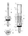
图1是实施本发明的一孔锯组件的分解的立体图;Figure 1 is an exploded perspective view of a hole saw assembly embodying the present invention;
图2是实施本发明的一孔锯组件的底部心轴的侧视图;Figure 2 is a side view of the bottom arbor of a hole saw assembly embodying the present invention;
图3是图2的心轴的俯视图;Figure 3 is a top view of the mandrel of Figure 2;
图4是当孔锯和底部安装在心轴上时的孔锯组件的侧视图;Figure 4 is a side view of the hole saw assembly when the hole saw and base are mounted on the mandrel;
图5是示出孔锯底部与心轴接合的局部剖视图;Figure 5 is a partial cross-sectional view showing the bottom of the hole saw engaged with the mandrel;
图6是心轴的锁定机构处于锁定或偏置位置时的详细的局部的下侧立体图;Figure 6 is a detailed partial underside perspective view of the locking mechanism of the mandrel in the locked or biased position;
图7是处于未锁定位置的图6的机构;Figure 7 is the mechanism of Figure 6 in an unlocked position;
图8是实施本发明的另一孔锯和底部在形成一体时的立体图;Fig. 8 is a perspective view of another hole saw embodying the present invention and the base when integrally formed;
图9是实施本发明的一较大直径的孔锯和底部的立体图;Figure 9 is a perspective view of a larger diameter hole saw and base embodying the present invention;
图10是实施本发明的孔锯组件的立体图,该孔锯组件具有两个孔锯,一个在另一个的里面,用于引导较大的孔锯;Figure 10 is a perspective view of a hole saw assembly embodying the present invention, the hole saw assembly having two hole saws, one inside the other, for guiding a larger hole saw;
图11是按照本发明的还有一实施例的孔锯组件的立体图,其中,孔锯底部的轴容纳在心轴内,并不突出通过其上表面;11 is a perspective view of a hole saw assembly in accordance with yet another embodiment of the present invention wherein the shaft at the bottom of the hole saw is received within the mandrel and does not protrude through its upper surface;
图12是图11的孔锯和底部的立体图,示出较短的轴;以及Figure 12 is a perspective view of the hole saw and base of Figure 11, showing the shorter shaft; and
图13是孔锯和底部安装到心轴时的图11的孔锯组件的横截面图。13 is a cross-sectional view of the hole saw assembly of FIG. 11 with the hole saw and base mounted to the arbor.
具体实施方式Detailed ways
本发明的以下详细描述参照附图。虽然描述包括示范的实施例,但其他实施例也是可能的,在不离开本发明的精神和范围的情况下可对描述的实施例作出修改。无论什么情况,将使用相同的标号贯穿诸附图和以下的描述,以表示相同或类似的零件。The following detailed description of the invention refers to the accompanying drawings. While the description includes exemplary embodiments, other embodiments are possible, and modifications may be made to the described embodiments without departing from the spirit and scope of the invention. Wherever possible, the same reference numbers will be used throughout the drawings and the following description to refer to the same or like parts.
参照图1至5,图中示出一孔锯组件10,它包括一孔锯12、底部14和心轴16。Referring to FIGS. 1-5 , there is shown a
孔锯12包括一在一端具有切削齿20的圆柱形体18。孔锯12的相对端包括一螺纹孔22(带有内螺纹),邻近孔22的孔锯体18的外表面包括沿圆周设置的台肩24,以使诸如扳手的工具(未示出)接合于孔锯12而使它转动。The
底部14包括圆盘26。从圆盘26共轴线地延伸的是一螺纹的突出件28(带有外螺纹),其尺寸和形状可与孔22啮合,这样,能使孔锯12紧紧地拧在底部。圆盘26包括用于与工具接合的台肩30。本技术领域内的那些熟练人士将会认识到:通过使用两个工具,一个在孔锯12上,另一个在底部14上,孔锯也可从底部移去。The
邻近圆盘26的边缘并沿与突出件28相对的方向延伸的是两个相同的轴32和34。由于两轴执行相同的功能并以完全相同的方式操作,所以,在以下的描述中将仅对一个作说明。然而,可以理解的是,所作的描述等同地适用于两者。Adjacent to the edge of the
轴32包括一圆柱36,它从圆盘延伸并使用业已知晓的技术(诸如,螺纹或压配合)连接于圆盘。邻近圆柱36外端的是出屑槽40,然后,圆柱具有一固定在其外端上的斜切的顶帽42,其外直径等于圆柱36的直径。
心轴16包括一与钻头46共轴线地延伸的纵向体44,钻头44可转动地附连在纵向体44上。沿与钻头46相对方向延伸的是一具有台肩50的柄轴48,并可以本技术领域内众所周知的方式插入一钻机内(未示出)。纵向体44包括两个孔52和54,其位置和尺寸允许轴32和34插入其内和从中穿过,轴32可插入孔52中,轴34可插入孔54中。一般地,孔52和54的直径能有效地使轴安装到纵向体44内。The
纵向体44的长度与从圆盘26至出屑槽40的轴圆柱36的长度相同,这样,当轴32插入纵向体44内时,出屑槽和顶帽突出纵向体44之外。The length of the
位于纵向体44顶部上的是一同轴的环形套筒或圆环56,可转动地在第一和第二位置之间移动。环形套筒56包括两相应的形状和尺寸的孔58和60,当环形套筒在第一位置时它们与孔52和54对齐,当环形套筒在第二位置时与孔52和54不对齐。Located on top of the
本技术领域内的那些熟练人士将会认识到,当环形套筒与纵向体对齐时,轴出屑槽40和顶帽42延伸入环形套筒内。环形套筒56的厚度等于出屑槽40的宽度,这样,当完全插入心轴时,仅顶帽42延伸越过环形套筒56的表面。Those skilled in the art will recognize that the
当环形套筒在第二位置时使轴32完全地插入心轴,环形套筒62的上表面接合顶帽42的唇缘64,有效地防止轴32从心轴16缩回。因此,这有效地将底部14和孔锯12锁定到心轴16上,以使孔锯能用于钻孔。When the annular sleeve is in the second position so that the
环形套筒向第二位置,即锁定的位置偏置,且必须施加一转动力将它转动至第一位置以使轴32和34缩回。从偏置的第二位置至第一位置的转动,一般地沿与钻机转动的方向相同。The annular sleeve is biased toward the second, locked position, and a rotational force must be applied to rotate it to the first position to retract the
熟练人士将会认识到,本发明的钻孔组件使孔锯和底部能够非常快速地安装到已安装在一钻机内的心轴上并可快速地从其中卸下。由于孔锯的直径不依赖于底部和心轴的尺寸,所以,使用者可具有多个孔锯,它们通过在第一与第二位置之间转动环形套筒而简单地安装到心轴和从其中拆下。Those skilled in the art will appreciate that the drilling assembly of the present invention enables the hole saw and bottom to be very quickly mounted on and removed from a mandrel already installed in a drilling machine. Since the diameter of the hole saw is not dependent on the size of the base and arbor, a user can have multiple hole saws that are simply mounted to and from the arbor by rotating the annular sleeve between the first and second positions. Remove it.
然而,为了进一步帮助快速地将孔锯底部14安装于心轴16,在环形套筒56的下侧68上的58和60的圆周边缘(即,面对底部44的表面)可成锥形或倒角。当轴32和34插入心轴通过孔52和54及孔58和60时,顶帽迫使环形套筒转动至第一位置。当顶帽超过环形套筒的上表面时,偏置装置使它卡入回到其偏置位置,由此,锁定底部和孔锯在心轴内。这对工具操作者提供一自动的“搭锁配合(snap-fit)”的结构。However, to further assist in quickly mounting the
纵向体44一般使用一埋头螺钉70夹紧在钻头46上。然而,它可同样地使用熟练人士业已知晓的其他普通技术进行连接。The
环形套筒使用卡簧固定在位。为了防止卡簧的转动,它可能会有效地阻挡一孔径58或60,可使用一尖头(未示出)或突出物以相对于环形套筒锁定卡簧。The ring sleeve is held in place with a circlip. To prevent rotation of the circlip, which may effectively block an
现参照图6和7,图中详细地示出环形套筒56和特殊的偏置结构(biasingarrangement)。环形套筒包括一凹槽74,在其内定位偏置装置,一般为一弹簧(未示出)。在凹槽的一端定位一在其内可滑动地移动销78的通道76。销接合在纵向体44内一对应的成形的孔(未示出)中,由此,当环形套筒放置在纵向体的顶部时,它锁定在位置内。如图3所示,销可有效地在其中移动的通道76的长度(在图6和7中示出的两位置)限制了环形套筒的转动。Referring now to Figures 6 and 7, the
在一较佳的实施例中,孔锯可与接合心轴的轴一体地制成。该实施例在图8中被示出,从图中可见,孔锯80具有一体的轴82和84,其形状和功能与先前讨论的相同。这种孔锯例如可使用机加工或金属铸造工艺制造。该实施例的一个优点是减少制造的零件,因而能减少成本。In a preferred embodiment, the hole saw is integrally formed with the shaft engaging the mandrel. This embodiment is shown in FIG. 8, from which it can be seen that a
为了帮助操作轴,它们可包括可用一工具接合的诸台肩86,台肩也是先前实施例的一特征。To aid in manipulating the shafts, they may include
在孔锯具有较大直径的情形中,如图9所示,孔锯88可不使用螺纹啮合件连接于底部90,而是使用螺钉92和94,它们贯穿在孔锯底部内的孔96和98,并各自地啮合轴100和102的端部,由此,将孔锯锁定至底部90。In the case of a hole saw having a larger diameter, as shown in FIG. 9, the
在另一实施例中,底部14的突出件28(如图1-5所示)可制成比目前已知的长度长。这使两孔锯可安装在一底部上。这是在以下情况中特别有用的特征:操作者想要在一现有的孔上钻一个较大的孔,其中,选择较小孔锯的尺寸是现存孔的尺寸。然后,使用较小孔锯作为一有效的引导中心,以便能切出对称布置的较大的孔。如图10所示,按照该较佳实施例的孔锯组件包括沿纵向延伸超过较大的孔锯106的一较小的孔锯104。选定较小的孔锯104的直径,以使其外表面108接合于壁112内的孔110的内表面。较小的孔锯104确保当孔锯106接合壁时它不会转动,因而,保证在壁内切出的较大的孔114与较小的孔110共轴线。In another embodiment, the
图11至13示出的是一按照本发明另一较佳实施例的孔锯组件。在该实施例中,孔锯12和底部26与上面所述的是相同的类型。然而,轴116和118的整体长度稍微短一些,轴仍具有出屑槽40和顶帽42。假设底部和环形套筒有相同的尺寸,在现有实施例中,较短的轴致使轴不是如先前的实施例中的情形那样突出超过环形套筒。这在图11和13中清楚地被示出,由图可见,轴116和118没有突出超过环形套筒122的上表面120。11 to 13 show a hole saw assembly according to another preferred embodiment of the present invention. In this embodiment, the
由于轴116和118不再突出超过环形套筒56,所以,前面描述的心轴至轴的锁定技术不再可用。为此原因,邻近环形套筒56的上表面120的孔124和126局部地扩大,以提供能由顶帽42的唇缘64接合的内台肩128。相应地,环形套筒孔124和126是圆形截面,仅用于从环形套筒底表面68起的出屑槽40的长度,然后,扩大以容纳环形套筒56的转动运动,以将轴116和118锁定和未锁定于心轴。Since the
该实施例克服为了阻止卡簧72的任何转动运动而对凹座或诸如此类结构的需要。还提供一视觉上更悦人的外观,并减少了顶帽夹住的风险。This embodiment overcomes the need for a recess or the like in order to prevent any rotational movement of the
在不背离本发明的范围的情况下,对本发明可很好地给出其它的优点和改进。虽然本发明已经示出和描述了本发明构想的最实际和较佳的实施例,但应该认识到,在本发明的精神和范围内,可从较佳实施例中作出改型,本发明不限于在此公开的细节,但与权利要求的全部范围相一致,以能包含任何的和所有等同的装置和设备。Other advantages and modifications may well be attributed to the invention without departing from the scope of the invention. While the invention has been shown and described the most practical and preferred embodiment contemplated by the invention, it should be recognized that modifications could be made from the preferred embodiment within the spirit and scope of the invention, and the invention is not intended to Be limited to the details disclosed herein, but be consistent with the full scope of the claims to encompass any and all equivalent means and devices.
在本发明以下任何的权利要求书和概述中,除了因表达的语言或必要的含义,上下文要求另有表述之外,所使用的词“包括”表示,规定的特征可同本发明的多种实施例内的特征联系在一起。In any following claims and summaries of the present invention, unless the context requires otherwise because of the language or essential meaning of the expression, the use of the word "comprising" means that the specified features can be combined with various aspects of the invention. Features within an embodiment are linked together.
Claims (18)
Applications Claiming Priority (2)
| Application Number | Priority Date | Filing Date | Title |
|---|---|---|---|
| AUPR7803AAUPR780301A0 (en) | 2001-09-21 | 2001-09-21 | Improved hole saw |
| AUPR7803 | 2001-09-21 |
Publications (2)
| Publication Number | Publication Date |
|---|---|
| CN1774319A CN1774319A (en) | 2006-05-17 |
| CN100434243Ctrue CN100434243C (en) | 2008-11-19 |
Family
ID=3831643
Family Applications (1)
| Application Number | Title | Priority Date | Filing Date |
|---|---|---|---|
| CNB02821305XAExpired - LifetimeCN100434243C (en) | 2001-09-21 | 2002-09-20 | Connector assembly, tool support assembly and hole saw assembly |
Country Status (8)
| Country | Link |
|---|---|
| US (3) | US7101124B2 (en) |
| EP (1) | EP1427575B1 (en) |
| CN (1) | CN100434243C (en) |
| AT (1) | ATE521462T1 (en) |
| AU (1) | AUPR780301A0 (en) |
| CA (1) | CA2460989C (en) |
| NZ (1) | NZ531613A (en) |
| WO (1) | WO2003024677A1 (en) |
Families Citing this family (77)
| Publication number | Priority date | Publication date | Assignee | Title |
|---|---|---|---|---|
| AUPR780301A0 (en)* | 2001-09-21 | 2001-10-11 | Keightley, Kym | Improved hole saw |
| ATE482045T1 (en)* | 2003-02-18 | 2010-10-15 | Greenlee Textron Inc | QUICK CHANGE SPINDLE UNIT FOR HOLE SAW |
| AU2003201841B2 (en)* | 2003-03-20 | 2005-04-07 | Kym John Keightley | A universal rotational connector |
| AU2003901440A0 (en)* | 2003-03-28 | 2003-04-10 | Keightley, Kym John | An improved hole saw boss |
| AU2003902866A0 (en)* | 2003-06-06 | 2003-06-26 | Kym John Keightley | A hole saw assembly |
| US7073992B2 (en) | 2003-06-24 | 2006-07-11 | Irwin Industrial Tool Company | Arbor for hole cutter and related method of use |
| GB2405115B (en)* | 2003-08-22 | 2007-05-02 | Kym John Keightley | Hole-saw assembly including two hole-saws |
| US8250823B2 (en)* | 2003-08-26 | 2012-08-28 | Ejot Gmbh & Co. Kg | Dowels and methods for the assembly of insulating panels |
| EP1555076A1 (en)* | 2004-01-17 | 2005-07-20 | A.V. Custom style B.V. | Quick change mandrel assembly and adapter for a hole saw and hole saw |
| US7621703B2 (en)* | 2004-06-08 | 2009-11-24 | Kym John Keightley | Hole saw assembly |
| AU2005251825B2 (en)* | 2004-06-08 | 2010-07-29 | Kym John Keightley | A hole saw assembly |
| ES2332054T3 (en)* | 2004-12-10 | 2010-01-25 | A.V. Custom Style B.V. | FAST MOUNTING TOOL HOLDER TREE WITH PLUG EJECTION, FOR A CROWN SAW. |
| EP1864734B1 (en)* | 2005-03-11 | 2013-06-05 | Kabushiki Kaisha Miyanaga | Core drill |
| AU304054S (en)* | 2005-06-03 | 2005-11-10 | Holesaw arbour | |
| AU304056S (en)* | 2005-06-03 | 2005-11-10 | Small holesaw boss | |
| US9022703B2 (en)* | 2005-06-08 | 2015-05-05 | Kym John Keightley | Hole saw assembly |
| WO2007036043A1 (en)* | 2005-09-28 | 2007-04-05 | Maxtech Manufacturing Inc. | Hole saw mandrel |
| GB0521697D0 (en)* | 2005-10-25 | 2005-11-30 | Rae Scott W | Holesaw + arbour holder |
| US20070166116A1 (en)* | 2006-01-18 | 2007-07-19 | Olson Dennis L | Hole cutter and guide |
| US7824137B2 (en)* | 2006-05-17 | 2010-11-02 | Maxtech Consumer Products Limited | Universal quick connect system for a hole saw |
| US7802948B1 (en)* | 2006-06-07 | 2010-09-28 | Matthew R Bastiaans | Drill extender |
| US7938600B1 (en)* | 2006-06-08 | 2011-05-10 | Milwaukee Electric Tool Corporation | Cutting tool and method of operating the same |
| US9421694B2 (en)* | 2006-11-28 | 2016-08-23 | Kym John Keightley | Hole saw assembly including drive shafts supported by a rotatable annulus |
| US8038372B2 (en) | 2007-04-13 | 2011-10-18 | Black & Decker Inc. | Push button holesaw mandrel assembly |
| US8038371B2 (en)* | 2007-04-13 | 2011-10-18 | Black & Decker Inc. | Push button holesaw mandrel assembly |
| DE102007022186A1 (en)* | 2007-05-11 | 2008-11-13 | Robert Bosch Gmbh | Adapter for operating a hole saw on a drive machine |
| US8025466B2 (en)* | 2007-05-16 | 2011-09-27 | Hunt Marty D | Removable countersink bit |
| USD571835S1 (en)* | 2007-05-22 | 2008-06-24 | Black & Decker Inc. | Push button holesaw mandrel |
| US9144909B2 (en)* | 2007-07-05 | 2015-09-29 | Re2, Inc. | Defense related robotic systems |
| WO2009015488A1 (en)* | 2007-08-01 | 2009-02-05 | Satnam Singh | Hole saw system with improved slug removability |
| ES2361129T3 (en)* | 2007-10-09 | 2011-06-14 | Abb Technology Ab | DEVICE OF INDUSTRIAL ROBOT, INDUSTRIAL ROBOT AND METHOD FOR HANDLING OBJECTS. |
| US8328474B2 (en) | 2008-03-06 | 2012-12-11 | Irwin Industrial Tool Company | Quick change arbor, hole cutter, and method |
| USRE46103E1 (en) | 2008-03-06 | 2016-08-16 | Irwin Industrial Tool Company | Quick change arbor, hole cutter, and method |
| US8366356B2 (en) | 2008-03-06 | 2013-02-05 | Irwin Industrial Tool Company | Quick change arbor, hole cutter, and method |
| US8360696B2 (en)* | 2008-03-18 | 2013-01-29 | Irwin Industrial Tool Company | Quick change arbor, hole cutter, and method |
| US8328476B2 (en)* | 2008-03-18 | 2012-12-11 | Irwin Industrial Tool Company | Quick change arbor, hole cutter, and method |
| US8434976B2 (en)* | 2009-03-20 | 2013-05-07 | Black & Decker Inc. | Small hole saw mandrel assembly |
| AU327724S (en)* | 2009-09-01 | 2009-09-28 | Fci Holdings Delaware | Profiled driver |
| US9884374B2 (en) | 2015-09-03 | 2018-02-06 | Irwin Industrial Tool Company | Hole cutter with multiple fulcrums |
| US8573907B2 (en) | 2010-01-13 | 2013-11-05 | Irwin Industrial Tool Company | Hole cutter with minimum tooth pitch to blade body thickness ratio |
| USD659176S1 (en) | 2010-01-13 | 2012-05-08 | Irwin Industrial Tool Company | Hole saw |
| US10137507B2 (en) | 2010-01-13 | 2018-11-27 | Irwin Industrial Tool Company | Hole cutter with multiple fulcrums |
| WO2011088271A1 (en) | 2010-01-13 | 2011-07-21 | Irwin Industrial Tool Company | Hole cutter with chip egress aperture |
| US9724766B2 (en) | 2010-01-13 | 2017-08-08 | Irwin Industrial Tool Company | Hole cutter with multiple fulcrums |
| USD690334S1 (en) | 2010-01-13 | 2013-09-24 | Irwin Industrial Tool Company | Hole saw |
| US9808869B2 (en) | 2010-01-13 | 2017-11-07 | Irwin Industrial Tool Company | Hole cutter with chip egress aperture |
| US8827604B1 (en)* | 2010-08-09 | 2014-09-09 | Tim Corey | Hole saw apparatus |
| US8858111B2 (en)* | 2010-12-15 | 2014-10-14 | James K. Donohue | Method and system of a quick-connector assembly |
| CN202224532U (en)* | 2011-09-29 | 2012-05-23 | 广州市启泰模具工业有限公司 | Upper die structure for numerical control punch die |
| DE102012204491A1 (en)* | 2012-03-21 | 2013-09-26 | Hilti Aktiengesellschaft | drilling |
| WO2014015154A1 (en) | 2012-07-18 | 2014-01-23 | Milwaukee Electric Tool Corporation | Hole saw |
| CN103111664B (en)* | 2013-02-01 | 2015-08-19 | 成都三锐工具制造有限公司 | Bimetal hole saw connects handle |
| WO2014153158A1 (en) | 2013-03-14 | 2014-09-25 | Icon Health & Fitness, Inc. | Strength training apparatus with flywheel and related methods |
| US9820757B2 (en)* | 2013-04-12 | 2017-11-21 | Greatbatch Ltd. | Instrument for reshaping the head of a femur |
| US9227240B2 (en)* | 2013-06-05 | 2016-01-05 | Conbraco Industries, Inc. | Crimping head for impact wrench |
| US9248513B2 (en)* | 2013-06-13 | 2016-02-02 | Rote Mate Industry Co., Ltd. | Quick-change attachment configuration for a hole saw |
| CN105848733B (en) | 2013-12-26 | 2018-02-13 | 爱康保健健身有限公司 | Magnetic resistance mechanism in hawser apparatus |
| WO2015191445A1 (en) | 2014-06-09 | 2015-12-17 | Icon Health & Fitness, Inc. | Cable system incorporated into a treadmill |
| US10940360B2 (en) | 2015-08-26 | 2021-03-09 | Icon Health & Fitness, Inc. | Strength exercise mechanisms |
| TWI644702B (en) | 2015-08-26 | 2018-12-21 | 美商愛康運動與健康公司 | Strength exercise mechanisms |
| US10293211B2 (en) | 2016-03-18 | 2019-05-21 | Icon Health & Fitness, Inc. | Coordinated weight selection |
| US10441840B2 (en) | 2016-03-18 | 2019-10-15 | Icon Health & Fitness, Inc. | Collapsible strength exercise machine |
| US10252109B2 (en) | 2016-05-13 | 2019-04-09 | Icon Health & Fitness, Inc. | Weight platform treadmill |
| CN106378835A (en)* | 2016-09-26 | 2017-02-08 | 卓拓精密工具(苏州)有限公司 | Novel long-service-life hard alloy drill bit |
| US10661114B2 (en) | 2016-11-01 | 2020-05-26 | Icon Health & Fitness, Inc. | Body weight lift mechanism on treadmill |
| US9821380B1 (en) | 2016-11-08 | 2017-11-21 | Hole Dynamics, LLC | Quick release hole saw |
| US10799959B2 (en)* | 2017-02-24 | 2020-10-13 | Milwaukee Electric Tool Corporation | Rotary power tool including threaded bit attachment |
| KR101926253B1 (en)* | 2017-03-15 | 2018-12-06 | 박종태 | A Holesaw system |
| USD845362S1 (en) | 2017-12-04 | 2019-04-09 | Black & Decker Inc. | Holesaw |
| TWI657904B (en)* | 2018-05-28 | 2019-05-01 | 久允工業股份有限公司 | Quick-release mechanism for saw blade of sawing tool and sawing tool using same |
| JP7442827B2 (en)* | 2018-06-12 | 2024-03-05 | カイトリー,キム | hole saw assembly |
| CN216028284U (en) | 2018-07-10 | 2022-03-15 | 米沃奇电动工具公司 | Hole saw |
| AU2020295404B2 (en) | 2019-06-20 | 2025-05-29 | Milwaukee Electric Tool Corporation | Hole saw with circular sidewall openings |
| US11446151B2 (en)* | 2019-06-27 | 2022-09-20 | DePuy Synthes Products, Inc. | Annular cutting tools for resecting a bone graft and related methods |
| USD958855S1 (en) | 2019-12-09 | 2022-07-26 | Milwaukee Electric Tool Corporation | Hole saw |
| AU2021202863A1 (en)* | 2020-05-08 | 2021-11-25 | kym keightlley | Hole cutter having plug ejection and method thereof |
| WO2025188627A1 (en)* | 2024-03-04 | 2025-09-12 | Maspbr, Llc | Spring-loaded arbor for use with a hole saw |
Citations (5)
| Publication number | Priority date | Publication date | Assignee | Title |
|---|---|---|---|---|
| US3973862A (en)* | 1975-06-02 | 1976-08-10 | Segal F | Pilot drill locating means for hole saw assembly |
| US4755087A (en)* | 1987-03-13 | 1988-07-05 | Parent Philip V | Hole saw plug ejector |
| GB2257381A (en)* | 1991-07-09 | 1993-01-13 | Eldon Tool Company Limited | Arbor for hole saw. |
| US5690452A (en)* | 1996-06-27 | 1997-11-25 | Baublits; David G. | Spring loaded automatic plug ejector or hole saws |
| EP1066902A2 (en)* | 1999-06-30 | 2001-01-10 | Nicotec Co., Ltd. | Separation type hole saw |
Family Cites Families (40)
| Publication number | Priority date | Publication date | Assignee | Title |
|---|---|---|---|---|
| US578487A (en)* | 1897-03-09 | Tapping attachment | ||
| US1045597A (en)* | 1911-08-31 | 1912-11-26 | Ideal Opening Die Company | Screw-cutting die. |
| US1939490A (en)* | 1930-06-30 | 1933-12-12 | Mummert Dixon Co | Compound tool |
| US2140192A (en)* | 1936-07-15 | 1938-12-13 | E C Atkins & Company | Hole saw blade |
| US2349400A (en)* | 1942-01-21 | 1944-05-23 | Milwaukee Electric Tool Corp | Saw |
| US2473077A (en)* | 1946-07-06 | 1949-06-14 | Jr Robert M Starbuck | Treapnning tool |
| US2484150A (en)* | 1946-12-10 | 1949-10-11 | Brown Robert Lee | Work-expelling device for tubular saws |
| US2794469A (en)* | 1954-01-11 | 1957-06-04 | Millers Falls Co | Hole saws |
| US2779361A (en)* | 1954-03-17 | 1957-01-29 | Miller Mfg Corp | Sawing tool for cutting circular holes |
| US3138183A (en)* | 1962-09-04 | 1964-06-23 | William S Stewart | Rotary saw control means |
| US3267975A (en)* | 1964-06-16 | 1966-08-23 | Black & Decker Mfg Co | Coupling means for hole saw assembly |
| US3390596A (en)* | 1965-09-01 | 1968-07-02 | Trevathan Sales Corp | Cutting head assembly |
| US3647310A (en)* | 1970-04-03 | 1972-03-07 | Mansfield K Morse | Universal hole saw arbor |
| US3731329A (en)* | 1970-12-11 | 1973-05-08 | Teledyne Inc | Die head |
| US3778179A (en)* | 1972-09-06 | 1973-12-11 | D Rivas | Dual replaceable holesaw bit |
| US3880546A (en)* | 1974-03-13 | 1975-04-29 | Segal F | Hole saw assembly |
| US4036560A (en) | 1975-11-03 | 1977-07-19 | Stanadyne, Inc. | Heavy duty hole saw and arbor assembly |
| US4148593A (en) | 1978-01-27 | 1979-04-10 | Stanadyne, Inc. | Hole saw assembly |
| US4669928A (en)* | 1986-10-07 | 1987-06-02 | Eugenio Mediavilla | Hole saw mandrel |
| JPH07100247B2 (en)* | 1989-10-11 | 1995-11-01 | 株式会社ハウスビーエム | Hole saw |
| US4968189A (en) | 1989-10-20 | 1990-11-06 | Pidgeon Joseph A | Hole saw driver-extruder and hole enlarger |
| JPH0818169B2 (en)* | 1990-08-28 | 1996-02-28 | 株式会社ミヤナガ | Core drill |
| US5076741A (en)* | 1990-11-13 | 1991-12-31 | Littlehorn James M | Plug ejecting holesaw |
| US5413437A (en)* | 1992-02-24 | 1995-05-09 | Bristow; Michael M. | Double-sided hole saw |
| US5226762A (en)* | 1992-08-06 | 1993-07-13 | Ecker Robert J | Sealed hole-saw arbor |
| US5352071A (en)* | 1993-06-07 | 1994-10-04 | Greenlee Textron Inc. | Hole saw arbor with retaining mechanism |
| JP2653640B2 (en)* | 1994-09-21 | 1997-09-17 | 株式会社ハウスビーエム | Mounting structure for cylindrical drilling tools |
| US5658102A (en)* | 1995-09-12 | 1997-08-19 | The L. S. Starrett Company | Hole saw arbor method and apparatus |
| US6065909A (en)* | 1998-10-30 | 2000-05-23 | Cook; John E. | Drill bit assembly with an adjustable hole saw |
| TW422149U (en)* | 1999-06-28 | 2001-02-11 | K & W Tools Co Ltd | Connecting device for hole-drilling saw |
| JP2001009612A (en) | 1999-06-30 | 2001-01-16 | Nicotec Co Ltd | Hole saw attaching/detaching device |
| JP3335604B2 (en) | 1999-08-05 | 2002-10-21 | 株式会社ニコテック | Separable hole saw |
| US6341925B1 (en)* | 2000-03-02 | 2002-01-29 | Roger J. Despres | Plug ejecting hole saw with twist-locking interchangeable saw cups |
| EP1193014B1 (en)* | 2000-09-01 | 2004-07-07 | Credo Technology Corporation | Mandrel assembly for hole saw and drill bit |
| AUPR780301A0 (en)* | 2001-09-21 | 2001-10-11 | Keightley, Kym | Improved hole saw |
| US6676343B2 (en)* | 2001-10-02 | 2004-01-13 | Donald E. Burk | Hole enlarging bit for power drills |
| AU2003901440A0 (en)* | 2003-03-28 | 2003-04-10 | Keightley, Kym John | An improved hole saw boss |
| AU2003902866A0 (en)* | 2003-06-06 | 2003-06-26 | Kym John Keightley | A hole saw assembly |
| GB2405115B (en)* | 2003-08-22 | 2007-05-02 | Kym John Keightley | Hole-saw assembly including two hole-saws |
| US6942437B2 (en)* | 2003-12-16 | 2005-09-13 | Ingersoll Cutting Tool Company | Milling cutting tool having cutter body mated to an adapter |
- 2001
- 2001-09-21AUAUPR7803Apatent/AUPR780301A0/ennot_activeAbandoned
- 2002
- 2002-09-20EPEP02766962Apatent/EP1427575B1/ennot_activeExpired - Lifetime
- 2002-09-20CACA002460989Apatent/CA2460989C/ennot_activeExpired - Lifetime
- 2002-09-20ATAT02766962Tpatent/ATE521462T1/ennot_activeIP Right Cessation
- 2002-09-20NZNZ531613Apatent/NZ531613A/ennot_activeIP Right Cessation
- 2002-09-20USUS10/469,883patent/US7101124B2/ennot_activeExpired - Lifetime
- 2002-09-20CNCNB02821305XApatent/CN100434243C/ennot_activeExpired - Lifetime
- 2002-09-20WOPCT/AU2002/001296patent/WO2003024677A1/ennot_activeApplication Discontinuation
- 2006
- 2006-09-01USUS11/515,095patent/US20070003386A1/ennot_activeAbandoned
- 2007
- 2007-09-07USUS11/851,507patent/US7959371B2/ennot_activeExpired - Fee Related
Patent Citations (5)
| Publication number | Priority date | Publication date | Assignee | Title |
|---|---|---|---|---|
| US3973862A (en)* | 1975-06-02 | 1976-08-10 | Segal F | Pilot drill locating means for hole saw assembly |
| US4755087A (en)* | 1987-03-13 | 1988-07-05 | Parent Philip V | Hole saw plug ejector |
| GB2257381A (en)* | 1991-07-09 | 1993-01-13 | Eldon Tool Company Limited | Arbor for hole saw. |
| US5690452A (en)* | 1996-06-27 | 1997-11-25 | Baublits; David G. | Spring loaded automatic plug ejector or hole saws |
| EP1066902A2 (en)* | 1999-06-30 | 2001-01-10 | Nicotec Co., Ltd. | Separation type hole saw |
Also Published As
| Publication number | Publication date |
|---|---|
| EP1427575A4 (en) | 2008-08-13 |
| ATE521462T1 (en) | 2011-09-15 |
| US20070003386A1 (en) | 2007-01-04 |
| US20040179911A1 (en) | 2004-09-16 |
| CA2460989A1 (en) | 2003-03-27 |
| NZ531613A (en) | 2007-11-30 |
| US7101124B2 (en) | 2006-09-05 |
| EP1427575A1 (en) | 2004-06-16 |
| AUPR780301A0 (en) | 2001-10-11 |
| US7959371B2 (en) | 2011-06-14 |
| EP1427575B1 (en) | 2011-08-24 |
| US20080019785A1 (en) | 2008-01-24 |
| WO2003024677A1 (en) | 2003-03-27 |
| CA2460989C (en) | 2009-08-18 |
| CN1774319A (en) | 2006-05-17 |
Similar Documents
| Publication | Publication Date | Title |
|---|---|---|
| CN100434243C (en) | Connector assembly, tool support assembly and hole saw assembly | |
| US9421694B2 (en) | Hole saw assembly including drive shafts supported by a rotatable annulus | |
| EP1449606B1 (en) | Universal quick change hole saw arbor | |
| US7513722B2 (en) | Collet collar stop for a drill bit | |
| EP1753575B1 (en) | A hole saw assembly | |
| US20100247258A1 (en) | Hole saw assembly | |
| JP2668284B2 (en) | Tool holder with tool change mechanism | |
| EP0970769B1 (en) | Drill bit and method of manufacturing same | |
| EP2845673B1 (en) | Arbor assembly and method of assembly | |
| AU2003201841B2 (en) | A universal rotational connector | |
| US5871310A (en) | Device for and method of enlarging and center displacing an opening in a work piece | |
| US2942500A (en) | Slip head drill bushing | |
| AU2002331447B2 (en) | An improved hole saw assembly | |
| EP3003614A1 (en) | Locking mechanism for a collet assembly and collet assembly including a locking mechanism | |
| AU2002331447A1 (en) | An improved hole saw assembly | |
| US10245655B2 (en) | Colleted bushing and method of use | |
| AU2014246680A1 (en) | A hole saw assembly including drive shafts supported by a rotatable annulus | |
| AU2013245495B2 (en) | A hole saw assembly | |
| AU2010100589A4 (en) | A hole saw assembly | |
| AU2005251825B2 (en) | A hole saw assembly |
Legal Events
| Date | Code | Title | Description |
|---|---|---|---|
| C06 | Publication | ||
| PB01 | Publication | ||
| C10 | Entry into substantive examination | ||
| SE01 | Entry into force of request for substantive examination | ||
| C14 | Grant of patent or utility model | ||
| GR01 | Patent grant | ||
| CX01 | Expiry of patent term | ||
| CX01 | Expiry of patent term | Granted publication date:20081119 |