CN100432753C - Display device, driving device of display device, and driving device of light source for display device - Google Patents
Display device, driving device of display device, and driving device of light source for display deviceDownload PDFInfo
- Publication number
- CN100432753C CN100432753CCNB2005101250005ACN200510125000ACN100432753CCN 100432753 CCN100432753 CCN 100432753CCN B2005101250005 ACNB2005101250005 ACN B2005101250005ACN 200510125000 ACN200510125000 ACN 200510125000ACN 100432753 CCN100432753 CCN 100432753C
- Authority
- CN
- China
- Prior art keywords
- voltage
- display panel
- lamp
- light
- panel
- Prior art date
- Legal status (The legal status is an assumption and is not a legal conclusion. Google has not performed a legal analysis and makes no representation as to the accuracy of the status listed.)
- Expired - Fee Related
Links
Images


Classifications
- G—PHYSICS
- G09—EDUCATION; CRYPTOGRAPHY; DISPLAY; ADVERTISING; SEALS
- G09G—ARRANGEMENTS OR CIRCUITS FOR CONTROL OF INDICATING DEVICES USING STATIC MEANS TO PRESENT VARIABLE INFORMATION
- G09G3/00—Control arrangements or circuits, of interest only in connection with visual indicators other than cathode-ray tubes
- G09G3/20—Control arrangements or circuits, of interest only in connection with visual indicators other than cathode-ray tubes for presentation of an assembly of a number of characters, e.g. a page, by composing the assembly by combination of individual elements arranged in a matrix no fixed position being assigned to or needed to be assigned to the individual characters or partial characters
- G09G3/34—Control arrangements or circuits, of interest only in connection with visual indicators other than cathode-ray tubes for presentation of an assembly of a number of characters, e.g. a page, by composing the assembly by combination of individual elements arranged in a matrix no fixed position being assigned to or needed to be assigned to the individual characters or partial characters by control of light from an independent source
- G09G3/3406—Control of illumination source
- G—PHYSICS
- G02—OPTICS
- G02F—OPTICAL DEVICES OR ARRANGEMENTS FOR THE CONTROL OF LIGHT BY MODIFICATION OF THE OPTICAL PROPERTIES OF THE MEDIA OF THE ELEMENTS INVOLVED THEREIN; NON-LINEAR OPTICS; FREQUENCY-CHANGING OF LIGHT; OPTICAL LOGIC ELEMENTS; OPTICAL ANALOGUE/DIGITAL CONVERTERS
- G02F1/00—Devices or arrangements for the control of the intensity, colour, phase, polarisation or direction of light arriving from an independent light source, e.g. switching, gating or modulating; Non-linear optics
- G02F1/01—Devices or arrangements for the control of the intensity, colour, phase, polarisation or direction of light arriving from an independent light source, e.g. switching, gating or modulating; Non-linear optics for the control of the intensity, phase, polarisation or colour
- G02F1/13—Devices or arrangements for the control of the intensity, colour, phase, polarisation or direction of light arriving from an independent light source, e.g. switching, gating or modulating; Non-linear optics for the control of the intensity, phase, polarisation or colour based on liquid crystals, e.g. single liquid crystal display cells
- G02F1/133—Constructional arrangements; Operation of liquid crystal cells; Circuit arrangements
- G02F1/1333—Constructional arrangements; Manufacturing methods
- G02F1/1335—Structural association of cells with optical devices, e.g. polarisers or reflectors
- G02F1/1336—Illuminating devices
- G—PHYSICS
- G02—OPTICS
- G02F—OPTICAL DEVICES OR ARRANGEMENTS FOR THE CONTROL OF LIGHT BY MODIFICATION OF THE OPTICAL PROPERTIES OF THE MEDIA OF THE ELEMENTS INVOLVED THEREIN; NON-LINEAR OPTICS; FREQUENCY-CHANGING OF LIGHT; OPTICAL LOGIC ELEMENTS; OPTICAL ANALOGUE/DIGITAL CONVERTERS
- G02F1/00—Devices or arrangements for the control of the intensity, colour, phase, polarisation or direction of light arriving from an independent light source, e.g. switching, gating or modulating; Non-linear optics
- G02F1/01—Devices or arrangements for the control of the intensity, colour, phase, polarisation or direction of light arriving from an independent light source, e.g. switching, gating or modulating; Non-linear optics for the control of the intensity, phase, polarisation or colour
- G02F1/13—Devices or arrangements for the control of the intensity, colour, phase, polarisation or direction of light arriving from an independent light source, e.g. switching, gating or modulating; Non-linear optics for the control of the intensity, phase, polarisation or colour based on liquid crystals, e.g. single liquid crystal display cells
- G02F1/133—Constructional arrangements; Operation of liquid crystal cells; Circuit arrangements
- G02F1/1333—Constructional arrangements; Manufacturing methods
- G02F1/1345—Conductors connecting electrodes to cell terminals
- G02F1/13452—Conductors connecting driver circuitry and terminals of panels
- G—PHYSICS
- G02—OPTICS
- G02F—OPTICAL DEVICES OR ARRANGEMENTS FOR THE CONTROL OF LIGHT BY MODIFICATION OF THE OPTICAL PROPERTIES OF THE MEDIA OF THE ELEMENTS INVOLVED THEREIN; NON-LINEAR OPTICS; FREQUENCY-CHANGING OF LIGHT; OPTICAL LOGIC ELEMENTS; OPTICAL ANALOGUE/DIGITAL CONVERTERS
- G02F1/00—Devices or arrangements for the control of the intensity, colour, phase, polarisation or direction of light arriving from an independent light source, e.g. switching, gating or modulating; Non-linear optics
- G02F1/01—Devices or arrangements for the control of the intensity, colour, phase, polarisation or direction of light arriving from an independent light source, e.g. switching, gating or modulating; Non-linear optics for the control of the intensity, phase, polarisation or colour
- G02F1/13—Devices or arrangements for the control of the intensity, colour, phase, polarisation or direction of light arriving from an independent light source, e.g. switching, gating or modulating; Non-linear optics for the control of the intensity, phase, polarisation or colour based on liquid crystals, e.g. single liquid crystal display cells
- G02F1/133—Constructional arrangements; Operation of liquid crystal cells; Circuit arrangements
- G02F1/1333—Constructional arrangements; Manufacturing methods
- G02F1/133342—Constructional arrangements; Manufacturing methods for double-sided displays
- G—PHYSICS
- G09—EDUCATION; CRYPTOGRAPHY; DISPLAY; ADVERTISING; SEALS
- G09G—ARRANGEMENTS OR CIRCUITS FOR CONTROL OF INDICATING DEVICES USING STATIC MEANS TO PRESENT VARIABLE INFORMATION
- G09G2320/00—Control of display operating conditions
- G09G2320/06—Adjustment of display parameters
- G09G2320/0626—Adjustment of display parameters for control of overall brightness
Landscapes
- Physics & Mathematics (AREA)
- Nonlinear Science (AREA)
- General Physics & Mathematics (AREA)
- Engineering & Computer Science (AREA)
- Mathematical Physics (AREA)
- Chemical & Material Sciences (AREA)
- Crystallography & Structural Chemistry (AREA)
- Optics & Photonics (AREA)
- Computer Hardware Design (AREA)
- Theoretical Computer Science (AREA)
- Control Of Indicators Other Than Cathode Ray Tubes (AREA)
Abstract
Translated fromChinese
Description
Translated fromChinese技术领域technical field
本发明涉及显示装置、显示装置的驱动装置以及用于该显示装置的光源的驱动装置。The present invention relates to a display device, a drive device for the display device, and a drive device for a light source used in the display device.
背景技术Background technique
等离子体显示板(PDP)是利用气体放电产生的等离子体显示字符或图像的装置,有机发光显示器(OLED)是利用电致发光显示字符或图像的装置。液晶显示器(LCD)通过将电场施加到两面板之间的液晶层,并调整电场强度以调节透过液晶层的光的透射率来显示预期图像的装置。A plasma display panel (PDP) is a device that displays characters or images using plasma generated by gas discharge, and an organic light-emitting display (OLED) is a device that uses electroluminescence to display characters or images. A liquid crystal display (LCD) is a device that displays desired images by applying an electric field to a liquid crystal layer between two panels, and adjusting the strength of the electric field to adjust the transmittance of light passing through the liquid crystal layer.
具有分别设置在内部和外部的显示面板并主要用于移动电话的显示装置,在下文称之为“双显示装置”,正发展成为中型/小型的显示装置。A display device having display panels respectively disposed inside and outside and mainly used in a mobile phone, hereinafter referred to as a "dual display device", is developing into a medium/small size display device.
双显示装置包括设置在内部的主显示面板;设置在外部的次显示装置;用于从外部装置接收信号、在其上安装有多个电路元件的印刷电路板(PCB);具有多个用来传输信号的信号线、连接到PCB并将来自次显示面板的信号施加到主显示面板的柔性印刷电路(FPC)板;以及控制它们的集成芯片。The dual display device includes a main display panel disposed inside; a secondary display device disposed externally; a printed circuit board (PCB) on which a plurality of circuit elements are mounted for receiving signals from the external device; Signal lines that transmit signals, flexible printed circuit (FPC) boards that connect to the PCB and apply signals from the sub display panel to the main display panel; and integrated chips that control them.
集成芯片产生用来控制主显示面板和次显示面板的驱动信号和控制信号,而且主要安装在COG(玻璃上的芯片)结构中的主显示面板上。The integrated chip generates driving signals and control signals for controlling the main display panel and the sub display panel, and is mainly mounted on the main display panel in a COG (chip on glass) structure.
由于使用双显示装置的产品通常是便携式的,因此产品通过已充电到预定电压的便携式电源供给电源电压。由于其上提供不同的功能和服务,需要处理的数据量增加了,功耗增加了,因此充电电压的使用时间逐渐减少。然而,随着产品在体积和重量方面都需要最小化,所以增加电源的容量很难。Since a product using a dual display device is generally portable, the product is supplied with a power supply voltage by a portable power supply charged to a predetermined voltage. Due to the different functions and services provided on it, the amount of data to be processed has increased, and the power consumption has increased, so the usage time of the charging voltage has gradually decreased. However, increasing the capacity of a power supply is difficult as products need to be minimized in terms of size and weight.
发明内容Contents of the invention
提供了用于显示装置的光源驱动装置,该光源包括多个彼此并联的灯,且每个灯具有第一端子和第二端子,该光源包括:灯的状态检测单元,其检测施加到每个灯的驱动电压,并将检测到的驱动电压与参考电压进行比较,以及为至少一个灯输出具有过电流状态通知信息的灯状态检测信号;以及变换器,该变换器通过施加AC电压将灯接通或关断,并基于灯状态检测信号控制AC电压,其中参考值是变化的,其取决于施加到每个灯的驱动电压的幅度。A light source driving device for a display device is provided, the light source includes a plurality of lamps connected in parallel, and each lamp has a first terminal and a second terminal, the light source includes: a state detection unit of the lamp, which detects the lamp driving voltage, and compares the detected driving voltage with a reference voltage, and outputs a lamp state detection signal having overcurrent state notification information for at least one lamp; and an inverter that connects the lamp to the lamp by applying an AC voltage. On or off, and control the AC voltage based on the lamp state detection signal, wherein the reference value is varied depending on the magnitude of the driving voltage applied to each lamp.
提供了显示装置,其包括:至少两个显示面板;多个将光传给显示面板的灯;以及灯控制单元,该灯控制单元用来基于外部施加的面板选择信号选择预定数量的灯,并选择其中的一个显示面板,通过点亮所选择的灯,将光提供给显示面板。There is provided a display device including: at least two display panels; a plurality of lamps transmitting light to the display panels; and a lamp control unit for selecting a predetermined number of lamps based on an externally applied panel selection signal, and One of the display panels is selected, and the selected lamp is turned on to supply light to the display panel.
显示面板可以包括第一显示面板和第二显示面板,且第一显示面板比第二显示面板大。The display panel may include a first display panel and a second display panel, and the first display panel is larger than the second display panel.
选择的灯面向第二显示面板的边缘。The selected lamp faces the edge of the second display panel.
当选择的显示面板是第二显示面板时,选择的灯的数量可以比当选择的显示面板是第一显示面板时选择的灯的数量少。When the selected display panel is the second display panel, the number of selected lamps may be less than that when the selected display panel is the first display panel.
显示装置可以是液晶显示装置。The display device may be a liquid crystal display device.
灯可以是发光二极管(LED)。The lights may be light emitting diodes (LEDs).
提供了显示装置,其中包括:第一印刷电路板(PCB),该印刷电路板包括多个灯,连接到灯的第一导线,连接到灯的多个其他的导线;柔性印刷电路(FPC)板,其包括分别连接到第一导线的第一信号线,连接到第二导线的多个信号线;第二PCB,其包括连接到第一信号线的第三导线和连接到第二信号线的多个第四导线;将第一电压施加到第三导线、将第二电压施加到第四导线,并基于外部面板选择信号控制第二电压施加的灯控制单元;以及同时由灯提供光的第一和第二显示面板,其中灯控制单元安装在第二PCB上,灯通过基于第一电压和第二电压之间的差而点亮,将光提供给第一和第二显示面板。A display device is provided, comprising: a first printed circuit board (PCB) including a plurality of lights, a first lead connected to the lights, a plurality of other leads connected to the lights; a flexible printed circuit (FPC) board, which includes first signal wires respectively connected to first wires, a plurality of signal wires connected to second wires; second PCB, which includes third wires connected to first signal wires and connected to second signal wires a plurality of fourth wires; a lamp control unit that applies the first voltage to the third wire, applies the second voltage to the fourth wire, and controls the application of the second voltage based on an external panel selection signal; and simultaneously provides light from the lamp The first and second display panels, in which the lamp control unit is mounted on the second PCB, provide light to the first and second display panels by turning on the lamp based on the difference between the first voltage and the second voltage.
第一电压可以比第二电压大。The first voltage may be greater than the second voltage.
灯可以是发光二极管(LED)。The lights may be light emitting diodes (LEDs).
第一电压可以公共地传输给每个LED的一个端子,第二电压分别传输给LED的其他端子,灯控制单元可以控制第二电压的施加,该第二电压施加到基于面板选择信号的LED的各个其他端子。The first voltage can be commonly transmitted to one terminal of each LED, and the second voltage can be transmitted to the other terminals of the LEDs respectively, and the lamp control unit can control the application of the second voltage, which is applied to the LEDs based on the panel selection signal. each other terminal.
提供了驱动显示装置的方法,其包括:读取外部面板选择信号;基于面板选择信号选择一个显示面板;基于选择面板选择预定数量的灯;并通过点亮选择的灯,将光提供给显示面板。该显示装置包括至少两个显示面板和多个将光传输给显示面板的灯。A method of driving a display device is provided, including: reading an external panel selection signal; selecting a display panel based on the panel selection signal; selecting a predetermined number of lamps based on the selection panel; and supplying light to the display panel by turning on the selected lamp . The display device includes at least two display panels and a plurality of lamps that transmit light to the display panels.
显示面板可以包括第一显示面板和第二显示面板,并且第一显示面板比第二显示面板大。The display panel may include a first display panel and a second display panel, and the first display panel is larger than the second display panel.
提供了包括第一显示面板、第二显示面板、以及多个同时将光提供给第一和第二显示面板的灯的显示装置,该显示装置包括:打开程度检测单元,其中基于显示装置的打开程度程度限定输出信号;灯控制单元,其基于来自打开程度检测单元的输出信号选择一个显示面板,基于选择的显示面板限定导通的灯的数量,并通过点亮限定数量的灯将光提供给第一和第二显示面板。There is provided a display device including a first display panel, a second display panel, and a plurality of lamps simultaneously providing light to the first and second display panels, the display device including: an opening degree detection unit, wherein based on the opening of the display device a degree limit output signal; a light control unit, which selects a display panel based on the output signal from the opening degree detection unit, limits the number of turned-on lights based on the selected display panel, and provides light to the light by turning on the limited number of lights first and second display panels.
第一显示面板可以比第二面板大,而且当选择的显示面板是第二显示面板时,选择的灯的数量可以比当选择的显示面板是第一显示面板时选择的灯的数量少。The first display panel may be larger than the second panel, and when the selected display panel is the second display panel, the number of selected lamps may be smaller than when the selected display panel is the first display panel.
显示装置可以是用于移动电话的显示装置。The display device may be a display device for a mobile phone.
灯可以是发光二极管。The lights may be light emitting diodes.
提供了显示装置,其包括:至少两个显示面板;多个将光提供给显示面板的灯;以及灯控制单元,该灯控制单元基于外部施加的面板选择信号改变施加到灯的信号,并选择其中的一个显示面板来调整来自灯的光的强度并将光提供给显示面板。A display device is provided, which includes: at least two display panels; a plurality of lamps supplying light to the display panels; and a lamp control unit that changes a signal applied to the lamps based on an externally applied panel selection signal, and selects One of the display panels adjusts the intensity of the light from the lamp and provides the light to the display panel.
灯控制单元可以选择预定数量的灯,通过调整施加给除选择的灯以外的剩下的灯的信号幅度改变光的强度。The lamp control unit may select a predetermined number of lamps, and change the intensity of light by adjusting the magnitude of signals applied to the remaining lamps except the selected lamps.
灯控制单元可以选择预定数量的灯,通过点亮所选择的灯,调整来自灯的光的强度。The lamp control unit may select a predetermined number of lamps, and adjust the intensity of light from the lamps by turning on the selected lamps.
显示面板可以包括第一显示面板和第二显示面板,其中第一显示面板比第二显示面板大。The display panel may include a first display panel and a second display panel, wherein the first display panel is larger than the second display panel.
选择的灯可以面向第二显示面板的边缘。The selected lamp may face the edge of the second display panel.
灯可以是发光二极管(LED)。The lights may be light emitting diodes (LEDs).
提供了包括至少两个显示面板和相对于一个显示面板彼此相对设置的多个灯的显示装置,其包括灯控制单元,该灯控制单元基于外部施加的面板选择信号选择预定数量的灯,并通过点亮选择的灯,将光提供给每个显示面板的至少一侧。There is provided a display device including at least two display panels and a plurality of lamps disposed opposite to each other with respect to one display panel, including a lamp control unit that selects a predetermined number of lamps based on an externally applied panel selection signal, and by Selected lamps are illuminated to provide light to at least one side of each display panel.
显示面板可以包括第一显示面板和第二显示面板,其中第一显示面板比第二显示面板大。The display panel may include a first display panel and a second display panel, wherein the first display panel is larger than the second display panel.
当基于面板选择信号选择的显示装置是第一显示面板时,灯控制单元可以将光提供给第一显示面板的两侧。When the display device selected based on the panel selection signal is the first display panel, the light control unit may provide light to both sides of the first display panel.
当基于面板选择信号选择的显示装置是第二显示面板时,灯控制单元可以将光提供给第二显示面板的一侧。When the display device selected based on the panel selection signal is the second display panel, the light control unit may provide light to one side of the second display panel.
显示面板可以是用于液晶显示装置的显示面板。The display panel may be a display panel for a liquid crystal display device.
灯可以是发光二极管(LED)。The lights may be light emitting diodes (LEDs).
提供了显示装置,其中包括:包括多个灯、连接到灯的第一导线和多个其他导线的第一印刷电路板(PCB);包括连接到第一导线的第一信号线和连接到第二导线的多个信号线的柔性印刷电路(FPC)板;包括连接到第一信号线的第三导线和连接到第二信号线的多个第四导线的第二PCB;将第一电压施加到第三导线、第二电压施加到第四导线、并基于外部面板选择信号控制第二电压施加的灯控制单元;以及由灯提供光的第一和第二显示面板,其中的灯控制单元安装在第二PCB上,灯相对于显示面板的一个显示面板彼此面对设置,并通过基于第一电压和第二电压之间的差值点亮灯,将光提供给第一和第二显示面板,其中一些灯仅仅对第一显示面板提供光。A display device is provided, including: a first printed circuit board (PCB) including a plurality of lamps, a first wire connected to the lamps, and a plurality of other wires; including a first signal line connected to the first wire and a first signal wire connected to the first wire. A flexible printed circuit (FPC) board of a plurality of signal lines of two wires; a second PCB including a third wire connected to the first signal line and a plurality of fourth wires connected to the second signal line; applying the first voltage to the third wire, the second voltage is applied to the fourth wire, and the lamp control unit that controls the application of the second voltage based on the external panel selection signal; and the first and second display panels that provide light from the lamp, wherein the lamp control unit is installed On the second PCB, the lamps are disposed facing each other with respect to one display panel of the display panels, and light is supplied to the first and second display panels by lighting the lamps based on the difference between the first voltage and the second voltage , some of which provide light only to the first display panel.
第一电压可以比第二电压大。The first voltage may be greater than the second voltage.
灯可以是发光二极管(LED)。The lights may be light emitting diodes (LEDs).
第一电压可被公共地传输给每个LED的一个端子,而第二电压分别传输给LED的其他端子,灯控制单元控制第二电压的施加,第二电压基于面板选择信号施加给LED的每个其他端子。The first voltage may be commonly transmitted to one terminal of each LED, while the second voltage is transmitted to the other terminals of the LEDs respectively, the lamp control unit controls the application of the second voltage, and the second voltage is applied to each LED based on the panel selection signal. other terminals.
提供了驱动显示装置的方法,该方法包括:读取外部面板选择信号;基于面板选择信号选择其中一个显示面板;基于选择面板选择预定数量的灯;并通过点亮选择的灯将光提供给每个显示面板的至少一侧。该显示装置包括至少两个显示面板和多个将光传输给显示面板的灯,该显示装置包括至少两个显示面板和多个相对于一个显示面板彼此相对设置、并将光传输给显示面板的灯。A method of driving a display device is provided, the method including: reading an external panel selection signal; selecting one of the display panels based on the panel selection signal; selecting a predetermined number of lamps based on the selection panel; and providing light to each at least one side of a display panel. The display device includes at least two display panels and a plurality of lamps that transmit light to the display panels, the display device includes at least two display panels and a plurality of lamps that are arranged opposite to each other with respect to one display panel and transmit light to the display panels. lamp.
显示面板可以包括第一显示面板和第二显示面板,其中第一显示面板比第二显示面板大。The display panel may include a first display panel and a second display panel, wherein the first display panel is larger than the second display panel.
当基于面板选择信号选择的显示面板是第一显示面板时,选择预定的灯可以将光提供给第一显示面板的两侧。When the display panel selected based on the panel selection signal is the first display panel, selecting predetermined lamps may provide light to both sides of the first display panel.
提供了显示装置,该显示装置包括第一显示面板、第二显示面板、以及多个相对于其中的一个显示面板彼此相对设置、并将光提供给第一和第二显示面板的灯,该显示装置包括:打开程度检测单元,其中基于显示装置的打开程度程度限定输出信号;用来基于来自打开程度检测单元的输出信号选择其中一个显示面板、基于所选择的显示面板限制要导通的灯的数量,以及通过点亮所限定数量的灯,将光提供给每个第一和第二显示面板的至少一侧的灯控制单元。A display device is provided, which includes a first display panel, a second display panel, and a plurality of lamps arranged opposite to each other with respect to one of the display panels and providing light to the first and second display panels, the display The device comprises: an opening degree detection unit, wherein the output signal is defined based on the degree of opening degree of the display device; and a device for selecting one of the display panels based on the output signal from the opening degree detection unit, limiting the lamps to be turned on based on the selected display panel. The light control unit provides light to at least one side of each of the first and second display panels by turning on the defined number of lights.
第一显示面板比第二显示面板大,当基于面板选择信号选择的显示面板是第一显示面板时,灯控制单元将光提供给第一显示面板的两侧。The first display panel is larger than the second display panel, and when the display panel selected based on the panel selection signal is the first display panel, the light control unit provides light to both sides of the first display panel.
显示装置可以是用于移动电话的显示装置。The display device may be a display device for a mobile phone.
灯可以是发光二极管。The lights may be light emitting diodes.
提供了显示装置,该显示装置包括至少两个显示面板和多个相对于其中的一个显示面板彼此相对设置、并将光提供给第一和第二显示面板的灯,该显示装置包括:灯控制单元,该灯控制单元基于外部施加的面板选择信号改变施加到灯的信号,并选择其中的一个显示面板来调整来自灯的光的强度并将光提供给每个显示面板的至少一侧。A display device is provided, the display device comprising at least two display panels and a plurality of lights disposed opposite each other with respect to one of the display panels and providing light to the first and second display panels, the display device comprising: a light control The lamp control unit changes a signal applied to the lamp based on an externally applied panel selection signal and selects one of the display panels to adjust the intensity of light from the lamp and provide light to at least one side of each display panel.
灯控制单元可以选择预定数量的灯,并通过调整施加到除选定的灯外的剩下的灯的信号幅度来改变光的强度。The lamp control unit may select a predetermined number of lamps, and change the intensity of light by adjusting the amplitude of signals applied to the remaining lamps except the selected lamp.
灯控制单元可以选择预定数量的灯,并通过点亮选定的灯,改变来自灯的光的强度。The lamp control unit may select a predetermined number of lamps and vary the intensity of light from the lamps by turning on the selected lamps.
显示面板可以包括第一显示面板和第二显示面板,其中第一显示面板比第二显示面板大。The display panel may include a first display panel and a second display panel, wherein the first display panel is larger than the second display panel.
选定的灯可以相对于第一显示面板彼此相对设置。Selected lights may be positioned opposite each other with respect to the first display panel.
灯可以是发光二极管。The lights may be light emitting diodes.
附图说明Description of drawings
参考附图,通过详细描述优选实施例,本发明将会变得更加清楚,其中:The present invention will become more apparent by describing in detail preferred embodiments with reference to the accompanying drawings, in which:
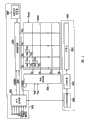
图1是根据本发明实施例的双LCD的分解透视图;1 is an exploded perspective view of a dual LCD according to an embodiment of the present invention;
图2是安装在图1中所示的双LCD的主显示面板上的LCD的框图;FIG. 2 is a block diagram of an LCD mounted on the main display panel of the dual LCD shown in FIG. 1;
图3是图2中所示的LCD的像素的等效电路图;FIG. 3 is an equivalent circuit diagram of a pixel of the LCD shown in FIG. 2;
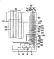
图4是根据本发明的实施例的、说明在印刷电路板(PCB)和用于灯的PCB上形成的信号线与用于灯的、在柔性印刷电路(FPC)板上形成的信号线之间的连接关系的示意图;4 is a diagram illustrating the relationship between signal lines formed on a printed circuit board (PCB) and the PCB for a lamp, and signal lines formed on a flexible printed circuit (FPC) board for the lamp, according to an embodiment of the present invention. A schematic diagram of the connection relationship between;
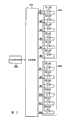
图5是根据本发明实施例的灯单元的电路图;5 is a circuit diagram of a lamp unit according to an embodiment of the present invention;
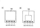
图6(A)、图6(B)是说明在发光二极管(LED)、主显示面板和次显示面板之间的位置关系图;6(A), FIG. 6(B) are diagrams illustrating the positional relationship among the light emitting diode (LED), the main display panel and the secondary display panel;
图7是根据本发明实施例的灯控制器的流程图;7 is a flowchart of a lamp controller according to an embodiment of the present invention;
图8是根据本发明的另一个实施例的、双LCD的分解透视图;8 is an exploded perspective view of a dual LCD according to another embodiment of the present invention;
图9是安装在图8中所示的双LCD主显示面板上的LCD的框图;FIG. 9 is a block diagram of an LCD mounted on the dual LCD main display panel shown in FIG. 8;
图10是根据本发明的另一个实施例的、说明在PCB和用于灯的PCB上形成的信号线与用于灯的、在柔性印刷电路(FPC)板上形成的信号线之间的连接关系的示意图;10 is a diagram illustrating connections between signal lines formed on the PCB and the PCB for the lamp and signal lines formed on the flexible printed circuit (FPC) board for the lamp according to another embodiment of the present invention. a schematic diagram of the relationship;
图11是根据本发明的另一个实施例的灯单元的电路图;11 is a circuit diagram of a lamp unit according to another embodiment of the present invention;
图12(A)、图12(B)是根据本发明的另一个实施例的、说明安装在主显示面板和次显示面板上的LED的发光状态。FIG. 12(A) and FIG. 12(B) illustrate the light-emitting states of LEDs installed on the main display panel and the sub-display panel according to another embodiment of the present invention.
具体实施方式Detailed ways
参考附图,以下将更加完整地描述本发明,附图中示出了本发明的优选实施例。The present invention will now be described more fully hereinafter with reference to the accompanying drawings, in which preferred embodiments of the invention are shown.
在附图中,为清楚起见,扩大了层和区域的厚度。全文用相同的附图标记表示相同的元件。很容易理解,当元件如层、膜、区域、基板或面板位于另一个元件“上”时,可以直接在另一个元件的上面或可存在中间元件。相反,当一个元件表示为“直接在”另一个元件“上”时,则没有中间元件。In the drawings, the thicknesses of layers and regions are exaggerated for clarity. The same reference numerals are used to refer to the same elements throughout. It will be readily understood that when an element such as a layer, film, region, substrate or panel is "on" another element, it can be directly on the other element or intervening elements may be present. In contrast, when an element is referred to as being "directly on" another element, there are no intervening elements present.
根参考附图,将描述据本发明的实施例的显示装置、该显示装置的驱动方法、以及用于该显示装置的光源的驱动装置。With reference to the accompanying drawings, a display device, a driving method of the display device, and a driving device of a light source for the display device according to embodiments of the present invention will be described.
参考图1到图6,现在将详细描述根据本发明的实施例的液晶显示装置(LCD),特别是用于具有主显示窗口和次显示窗口的移动电话的双LCD。1 to 6, a liquid crystal display device (LCD) according to an embodiment of the present invention, particularly a dual LCD for a mobile phone having a main display window and a sub display window, will now be described in detail.
图1是根据本发明的实施例的双LCD的分解透视图,图2是安装在图1中所示的双LCD的主显示面板上的LCD的框图,图3是图2中所示的LCD的像素的等效电路图,图4是根据本发明的实施例的、说明在印刷电路板(PCB)和用于灯的PCB上形成的信号线与用于灯的、在柔性印刷电路(FPC)板上形成的信号线之间的连接关系的示意图,图5是根据本发明实施例的灯单元的电路图,以及图6是说明在发光二极管(LED)、主显示面板和次显示面板之间的位置关系图。1 is an exploded perspective view of a dual LCD according to an embodiment of the present invention, FIG. 2 is a block diagram of an LCD mounted on a main display panel of the dual LCD shown in FIG. 1 , and FIG. 3 is an LCD of the LCD shown in FIG. 2 Figure 4 is an equivalent circuit diagram of a pixel according to an embodiment of the present invention, illustrating signal lines formed on a printed circuit board (PCB) and a PCB for a lamp, and a flexible printed circuit (FPC) for a lamp A schematic diagram of the connection relationship between the signal lines formed on the board, FIG. 5 is a circuit diagram of a lamp unit according to an embodiment of the present invention, and FIG. Location diagram.
参考图1,根据本发明的实施例的双LCD包括具有主显示面板330a、次显示面板330b以及背光单元900的LC模块310、一对包含该LC模块310的前和后底盘361和362、模型帧(mold frame)336、多个柔性印刷电路(FPC)板350、360以及370,以及印刷电路板(PCB)610。Referring to FIG. 1, a dual LCD according to an embodiment of the present invention includes an
主显示面板330a包括主LC面板组件300a、安装在主LC面板组件300a的集成芯片620以及施加在集成芯片620周围的保护膜621。The
次显示面板330b包括次LC面板组件300b。The
主显示面板330a比次显示面板330b大。The
主LC面板组件300a和次LC面板组件300b包括下部面板100a和100b,上部面板200a和200b,以及如图3所示,分别设置在两者之间的LC层3。The main
主LC面板组件300a的结构与次LC面板组件300b的结构相同,为方便描述,参考图2和3将只描述主LC面板组件300a。The structure of the main
下部面板100a包括多个显示信号线G1-Gn和D1-Dm,下部和上部面板100a和200a包括多个连接到显示信号线G1-Gn和D1-Dm、并在如图2和3中所示的电路图中基本上以矩阵的形式设置的像素。The
显示信号线G1-Gn和D1-Dm包括多个传输栅极信号(也称之为“扫描信号”)的栅极线G1-Gn和多个传输数据信号的数据线D1-Dm。栅极线G1-Gn基本上沿行的方向延伸,彼此基本上平行,而数据线D1-Dm基本上沿列的方向延伸,彼此基本上平行。The display signal lines G1-Gn and D1-Dm include a plurality of gate lines G1-Gn transmitting gate signals (also referred to as “scanning signals”) and a plurality of data lines D1-Dm transmitting data signals. The gate lines G1-Gn extend substantially in a row direction and are substantially parallel to each other, while the data lines D1-Dm extend substantially in a column direction and are substantially parallel to each other.
每个像素包括连接到显示信号线G1-Gn和D1-Dm的开关元件Q,以及连接到开关元件Q的LC电容器CLC和存储电容器CST。该存储电容器CST在其他实施例中可以省略。Each pixel includes a switching element Q connected to display signal lines G1-Gn and D1-Dm, and an LC capacitor CLC and a storage capacitor CST connected to the switching element Q. The storage capacitor CST may be omitted in other embodiments.
可以用TFT实现的开关元件Q设置在下部面板100a上。开关元件Q具有三个端子:连接到栅极线G1-Gn之一的控制端;连接到数据线D1-Dm之一的输入端;以及连接到LC电容器CLC和存储电容器CST的输出端。A switching element Q, which can be implemented with a TFT, is provided on the
LC电容器CLC包括作为两个端子的、设置在下部面板100a上的像素电极190和设置在上部面板200a上的公共电极270。设置在两个电极190和270之间的LC层3作为LC电容器CLC的电介质。像素电极190连接到开关元件Q,公共电极270提供有公共电压Vcom并覆盖上部面板200a的整个表面。在其他实施例中,公共电极270可以设置在下部面板100a上,电极190和270都可以具有条状或带状外形。The LC capacitor CLC includes, as two terminals, a
存储电容器CST是LC电容器CLC的辅助电容器。存储电容器CST包括像素电极190和独立的信号线,存储电容器CST设置在下部面板100a上,通过绝缘体与像素电极190重叠,并提供有预定的电压,如公共电压Vcom。或者,存储电容器CST包括像素电极190和相邻的栅极线,该相邻的栅极线称之为前一个栅极线,其通过绝缘体与像素电极190重叠。The storage capacitor CST is an auxiliary capacitor for the LC capacitor CLC . The storage capacitor CST includes the
为了彩色显示,每个像素唯一地表示一种原色(即,空间划分)或每个像素按顺序依次表示原色(即,时间划分),这样原色的空间或时间总和被识别为希望的颜色。一组原色的例子包括红、绿和蓝色。图3表示空间划分的例子,其中每个像素包括滤色器230,该滤色器表示在朝向像素电极190的上部面板200a的区域内的一个原色。或者,滤色器230设置在下部面板100a上的像素电极190的上面或下面。For color display, each pixel uniquely represents a primary color (i.e., spatial division) or each pixel sequentially represents a primary color (i.e., temporal division), such that the spatial or temporal sum of the primaries is identified as the desired color. An example set of primary colors includes red, green and blue. FIG. 3 shows an example of spatial division in which each pixel includes a
一个或多个用来偏振光的偏光器(未示出)附着在面板100a和200a的外表面。One or more polarizers (not shown) for polarizing light are attached to the outer surfaces of the
栅极驱动器400连接到栅极线G1-Gn,合成来自外部装置的栅极开启电压Von和栅极关闭电压Voff以产生用于施加到栅极线G1-Gn的栅极信号。栅极驱动器400和开关元件Q、显示信号线G1-Gn一起直接结合到主LC面板组件300a的下部面板100a上。The
如图1所示,集成芯片620直接安装在主LC面板组件300a的下部面板100a上(称之为COG(玻璃上的芯片)),即如图2所示,包括信号控制器600,连接到信号控制器600的数据驱动器500,以及连接到数据驱动器500的灰度电压发生器800。As shown in FIG. 1, the
灰度电压发生器800产生两组与像素传输有关的灰度电压。一组中的灰度电压相对于公共电压Vcom具有正极性,而在另一组中的那些相对于公共电压Vcom具有负极性。The
数据驱动器500包括多个安装在每个数据TCP 510上的IC芯片。The
数据驱动器500连接到主LC面板组件300a的数据线D1-Dm,并将由灰度电压发生器800提供的从灰度电压中选择的数据电压施加到数据线D1-Dm。The
信号控制器600连接到背光单元900并控制驱动器400和500,等等。The
如图1、2和4-6所示,背光单元900固定在模型帧336的短轴的边缘附近,包括向主LC面板组件330a和次LC面板组件300b发射光的灯单元910,连接到集成芯片620的信号控制器600并感应移动电话打开程度的打开程度传感器960、连接到打开程度传感器960和灯单元910的灯控制器970、在其上安装有灯单元910的PCB 950、将来自灯单元910的光引导到主LC面板组件300a和次LC面板组件300b并均匀保持光的强度的光导向板341、以及多个设置在光导向板341的下面和上面并确保亮度特性的光薄片342a和342b。As shown in Figures 1, 2 and 4-6, the
灯单元910包括多个LED L1-L6。在本实施例中,安装在灯单元910上的LED的数量为六个,但在其他实施例中,LED的数量可以基于LCD的运行来确定。The
如图6所示,在PCB 950上,LED L1-L6沿主显示面板330a的边缘设置在成行的方向上,以及对于次显示面板330b的边缘的中心左右对称地在成行的方向上进行设置。As shown in FIG. 6, on the
打开程度传感器960优选设置在移动电话的主体和双LCD之间连接的连接部分(未示出)上,其包括输出与基于来自移动电话主体的双LCD的打开程度限定的电阻有关的电压的感应装置等。然而,打开程度传感器的排列位置或运行特征在其他实施例中可以改变。The
基于来自打开程度传感器960的电压,灯控制器970控制灯单元910,该灯控制器970可以结合在PCB 610上。Based on the voltage from the
多个FPC板350、360和370包括在集成芯片620和PCB 610之间连接的主FPC板350、在主LC面板组件300a和次LC面板组件300b之间连接的次FPC板360、以及在PCB 950和PCB 610之间连接的FPC板370。A plurality of
如图4所示,多个信号线351和371-377形成在主FPC板350和FPC 370上。As shown in FIG. 4, a plurality of
每个信号线351通过触点(contact)619连接到形成在PCB 610上的多个导线621。信号线371-377通过触点619连接到多个形成在PCB 610上的导线622,并分别通过触点959连接到形成在PCB 950上的多个导线951-957。Each
信号线351和371-377包括传输用于驱动集成芯片620的电压、控制信号和数据等的信号线351、和用于给灯单元910的相应LED L1-L6传输驱动信号的信号线371-377。The signal lines 351 and 371-377 include
多个导线和传输控制信号和数据的信号线还可以形成在PCB 610、FPC板370和PCB 950上,导线和信号线的数量可以根据使用而变化。A plurality of wires and signal lines for transmitting control signals and data can also be formed on the
多个信号线可以形成在次FPC板360上,来自主LC面板组件300a的数据或控制信号可以通过数据或控制信号传输到次LC面板组件。A plurality of signal lines may be formed on the
前底盘361和后底盘362分别包括窗口365和366,PCP 610也包括窗口615。
通过窗口365露出主LC面板组件300a的显示区域。The display area of the main
次LC面板组件300b通过窗口366接收来自灯单元910的光,通过窗口615露出次LC面板组件300b的显示区域。The sub
多个连接到导线621和622的电路元件安装在PCB 610上。除导线621和622外,多个提供外部信号的导线(未示出)也形成在PCB 610上。前底盘361和后底盘362分别在模型帧363的上部和下部结合以完成双LCD,其中前底盘361和后底盘362包括LC模块310。A plurality of circuit elements connected to
现在,将详细描述双LCD的运行。Now, the operation of the dual LCD will be described in detail.
参考图2,从外部图形控制器(未示出)通过主FPC板350的信号线351和PCB 610的导线621向集成电路620的信号控制器600提供输入图像信号R、G和B,和控制其显示器的输入控制信号,其中输入控制信号例如为垂直同步信号Vsync、水平同步信号Hsync、主时钟MCLK以及数据启动信号DE。还向信号控制器600提供基于来自背光单元900的打开程度传感器960的双LCD打开程度的打开程度感应信号。2, the
根据打开程度感应信号,选择主LC面板组件300a和次LC面板组件300b中的一个后,产生栅极控制信号CONT1和数据控制信号CONT2,然后根据输入控制信号和输入图像信号R、G和B,处理图像信号R、G和B以适合于所选择的面板组件运行,信号控制器600给栅极驱动器400提供栅极控制信号CONT1,给数据驱动器500提供处理过的图像信号DAT和数据控制信号CONT2。According to the opening degree sensing signal, after selecting one of the main
作为选择,信号控制器600可以用独立电路元件或其他方法来选择主LC面板组件300a和次LC面板组件300b的其中一个。Alternatively, the
栅极控制信号CONT1包括扫描启动信号STV,该扫描启动信号STV用来指令栅极驱动器400开始扫描,并包括至少一个时钟信号用来控制栅极开启电压Von的输出时间。栅极控制信号CONT1还可以包括用来限定栅极开启电压Von持续时间的输出使能信号OE。The gate control signal CONT1 includes a scan start signal STV for instructing the
数据控制信号CONT2包括为一组像素通知数据传输开始的水平同步开始信号STH、指令数据驱动器500将数据电压施加到数据线D1-Dm的负载信号LOAD、以及数据时钟信号HCLK。该数据控制信号CONT2可以进一步包括用来反转数据电压(相对于公共电压Vcom)极性的反转信号RVS。The data control signal CONT2 includes a horizontal synchronization start signal STH notifying the start of data transfer for a group of pixels, a load signal LOAD instructing the
响应于来自信号控制器600的数据控制信号CONT2,数据驱动器500为来自信号控制器600的一组像素接收一图像数据DAT数据包,将图像数据DAT转换成从灰度电压发生器800提供的灰度电压中选择的模拟数据电压,并将数据电压施加到主LC面板组件300a或次LC面板组件300b的数据线D1-Dm。In response to the data control signal CONT2 from the
响应于来自信号控制器600的栅极控制信号CONT1,选择的主LC面板组件300a或次LC面板组件300b的栅极驱动器400将栅极开启电压Von施加到栅极线G1-Gn,然后导通连接于其上的开关元件Q。施加到数据线D1-Dm的数据电压通过激活的开关元件Q提供给像素。In response to the gate control signal CONT1 from the
可以通过数据线D1-Dm从信号控制器600或单独的装置向未被选择的主LC面板组件300a或次LC面板组件300b提供用于黑色的数据电压。The data voltage for black may be supplied from the
施加到像素的数据电压和公共电压Vcom的差表示为LC电容器CLc的充电电压,即像素电压。取决于像素电压的幅度,液晶分子具有方向性。The difference between the data voltage applied to the pixel and the common voltage Vcom is represented as the charging voltage of the LC capacitor CLc , ie, the pixel voltage. Depending on the magnitude of the pixel voltage, the liquid crystal molecules have directionality.
基于来自打开程度传感器960的打开程度感应信号,背光单元900控制灯单元910的发光。以下将描述背光单元900的运行。Based on the opening degree sensing signal from the
来自灯单元910的光通过LC层3传递,然后根据液晶分子的方向改变它的极性。偏光器将光偏振方向转换成光透射方向。Light from the
通过以水平周期(用“1H”表示,等于水平同步信号Hsync和数据使能信号DE的一个周期)为单位重复该过程,在一个帧内,所有栅极线G1-Gn被依次提供栅极开启电压Von,由此将数据电压施加到所有的像素。当一个帧结束,下一个帧开始时,控制施加到数据驱动器500的反转控制信号RVS以使数据电压的极性反转(称之为“帧反转”)。也可以控制反转控制信号RVS,这样在一个帧中数据线内流动的数据电压极性发生了反转(例如,线反转和点反转),或在一数据包内的数据电压的极性发生了反转(例如,列反转和点反转)。By repeating this process in units of a horizontal period (indicated by "1H", which is equal to one period of the horizontal synchronization signal Hsync and the data enable signal DE), within one frame, all the gate lines G1-Gn are sequentially provided with gate-on The voltage Von, thereby applying the data voltage to all the pixels. When one frame ends and the next frame starts, the inversion control signal RVS applied to the
现在,参考图2、4到7,将详细描述根据本发明的实施例的背光单元900的运行。Now, referring to FIGS. 2, 4 to 7, the operation of the
图7是根据本发明的实施例的灯控制器的流程图。7 is a flow diagram of a lamp controller according to an embodiment of the present invention.
如上所述,灯单元910包括多个LED L1-L6,其(+)端子共同连接到公共端子A,公共端子A连接到灯控制器970,并且(-)端子连接到相应的输出端子B1-B6,输出端子B1-B6分别连接到灯控制器970。As described above, the
以下将详细描述背光单元900的运行。The operation of the
将电源电压施加到背光单元900后,灯控制器970将LED L1-L6运行所需的电压,如大约3.3V施加给LED L1-L6的(+)端子。即,通过PCB 610的导线611传输的电压通过触点619传输到PCB 950的信号线951和FPC板370的信号线371,并施加到所有LED L1-L6的(+)端子。After applying the power supply voltage to the
然而,由于没有电压施加到输出端B1-B6,电流不通过LED L1-L6流动,因此LED L1-L6关断。However, since no voltage is applied to the outputs B1-B6, current does not flow through the LEDs L1-L6, and thus the LEDs L1-L6 are turned off.
然后,灯控制器970读取来自打开程度传感器960的打开程度感应信号(S101),并确定移动电话的打开程度(S102)。Then, the
当打开程度感应信号的电压大于预定电压,灯控制器970确定双LCD从移动电话的主体打开到预定量或更多。这样,灯控制器970确定主显示面板330a处于被选择来显示图像的状态。When the voltage of the opening degree sensing signal is greater than a predetermined voltage, the
因此,灯控制器970导通灯单元910的所有的LED L1-L6。为导通LEDL1-L6,灯控制器970通过PCB 610的导线612-617和FPC板370的信号线372-377分别将PCB 950的导线952-957接地。Therefore, the
这样,LED导通(S103),从而光同时传输到主LC面板组件300a和次LC面板组件300b。同时,次显示面板330b的栅极驱动器不将栅极开启电压Von传输给栅极线。因此,虽然用于主显示面板330a的数据电压施加到次LC面板组件300b的数据线,还是不能在次显示面板330b显示图像。In this way, the LED is turned on (S103), so that light is simultaneously transmitted to the main
接着,灯控制器970读取来自打开程度传感器960的打开程度感应信号,并确定移动电话的双LCD是否关闭(S101和S102)。Next, the
当打开程度感应信号的电压比预定电压小时,灯控制器970确定双LCD接近移动电话的主体。即,灯控制器970确定次显示面板330b处于被选择来显示图像的状态。When the voltage of the opening degree sensing signal is smaller than a predetermined voltage, the
接着,灯控制器970导通预定数量的LED一段预定时间,然后关断剩下的LED(S104和S105)。此时,如图6所示,设置在次显示面板330b的边缘附近的LED L2-L5导通,远离边缘设置的LED L1和L6的剩下部分关断。Next, the
通过点亮LED L2-L5,光提供给主LC面板组件300a和次LC面板组件300b。By lighting the LEDs L2-L5, light is provided to the main
此时,主显示面板330b的栅极驱动器400不将栅极开启电压Von传输给栅极线G1-Gn。因此,虽然次显示面板330b的数据电压施加到主显示面板330a的数据线D1-Dm,但是在主显示面板330a上不显示图像。At this time, the
考虑到次显示面板330b的尺寸和形状,要导通或关断的LED的数量和配置可以变化。The number and configuration of LEDs to be turned on or off may vary in consideration of the size and shape of the
为点亮LED L2-L5,灯控制器970停止电压的施加,即,连接到信号线612和617的LED L1和L6的(-)端子被接地(S106),以切断施加给输出端B1和B6的地。To light the LEDs L2-L5, the
此时,灯控制器970保持剩下的信号线613-616接地,这样输出端子B2-B5持续地接地。At this time, the
结果,当信号只是在比主显示面板330a小的次显示面板330b上显示时,基于选择的显示面板的尺寸,只有选择的LED导通,而不是点亮所有的LEDL1-L6以改变从灯单元910发射来的光的强度,因此电源不必要的消耗减少了。As a result, when the signal is only displayed on the
作为选择,一些相应于次显示面板330b的边缘设置的LED可以被提供大于施加到远离边缘而设置的剩下的LED的电压的电压,以改变灯单元910的强度。而且,当选择次显示面板330b时,灯单元910的强度可以通过减少施加到每个灯如LED L1-L6的电压来改变。Alternatively, some LEDs disposed corresponding to the edge of the
根据本发明的实施例,在包括多个显示面板(如主显示面板和次显示面板)的双LCD中,当图像是在小于主显示面板的次显示面板上显示时,预定数量的灯的强度改变了。这样,当不需要某些光时,由灯消耗的功率减少了,从而减少了双LCD的整个功率消耗。According to an embodiment of the present invention, in a dual LCD including a plurality of display panels (such as a main display panel and a sub display panel), when an image is displayed on a sub display panel smaller than the main display panel, the intensity of a predetermined number of lights changed. In this way, when some light is not needed, the power consumed by the lamp is reduced, thereby reducing the overall power consumption of the dual LCD.
接着,参考图8到12,将描述本发明的另一个实施例。和图1到7对比,用相同的附图标记表示进行相同运行的元件,并省略了其详细描述。Next, referring to Figs. 8 to 12, another embodiment of the present invention will be described. In contrast to FIGS. 1 to 7 , elements performing the same operations are denoted by the same reference numerals, and detailed descriptions thereof are omitted.
图8是根据本发明的另一个实施例的、双LCD的分解透视图,图9是安装在图8中所示的双LCD主显示面板上的LCD的框图;8 is an exploded perspective view of a dual LCD according to another embodiment of the present invention, and FIG. 9 is a block diagram of an LCD mounted on the dual LCD main display panel shown in FIG. 8;
不同于参考图1到7的根据本发明实施例的双LCD,根据本发明该实施例的双LCD包括具有多个LED L7-L12的灯单元920,以及具有LED L1-L6的灯单元910。这样,根据本发明该实施例的双LCD还包括在其上安装有灯单元920的PCB 960,以及和灯单元910一起安装的PCB 950。Unlike the dual LCD according to the embodiment of the present invention with reference to FIGS. 1 to 7, the dual LCD according to this embodiment of the present invention includes a
如图8所示,PCB 950位于模型帧336的边缘,即,靠近短轴的一个边缘,PCB 960位于PCB 950的相对位置附近,即,位于模型帧336的短轴的另一个边缘附近。As shown in FIG. 8 ,
除FPC板350、360和370以外,双LCD也包括在灯单元920和PCB 610之间传输信号或数据的FPC板380。In addition to the
如图8所示,通过前和后底盘361和362的窗口365和366分别露出主LC组件300a和次LC组件300b的显示区域。主LC组件300a通过接收来自灯单元910和920的光而显示图像,而次LC组件300b通过收来自灯单元910的光而显示图像。As shown in FIG. 8, the display areas of the
参考图8,灯单元910和920沿Y轴固定在模型帧336的两端,并且他们分别将光提供给主LC组件300a和次LC组件300b的至少一侧。Referring to FIG. 8,
除了以上所述的结构特征外,图8和9中所示的双LCD的结构基本上与图1和图2中所示的双LCD的结构相同,因此省略了详细描述。Except for the structural features described above, the structure of the dual LCD shown in FIGS. 8 and 9 is basically the same as that shown in FIGS. 1 and 2 , and thus a detailed description is omitted.
接着,参考图10,将详细描述用于灯910和920的在PCB 610及PCB 950和960上形成的信号线6以及信号线之间的关系。Next, referring to FIG. 10 , the signal lines 6 formed on the
图10是根据本发明的另一个实施例的、说明在PCB和用于灯的PCB形成的信号线以及用于灯的、在柔性印刷电路(FPC)板上形成的信号线之间的连接关系的示意图。10 is a diagram illustrating a connection relationship between a PCB and a signal line formed on a PCB for a lamp and a signal line formed on a flexible printed circuit (FPC) board for a lamp according to another embodiment of the present invention. schematic diagram.
参考图10,多个信号线351、371-377和381-387形成在主FPC板350、用于灯910和920的FPC板370和380上。Referring to FIG. 10 , a plurality of
在图10的左上部分所示的信号线351通过触点619连接到形成在PCB610上的多个导线621,并通过触点959连接到形成在PCB 950上的多个导线951-957。
同样的,在图10的右边部分示出的、形成在PFC板380上的信号线381-387通过触点619连接到形成在PCB 610上的多个导线642,并通过触点959连接到形成在PCB 950上的多个导线951和962-967。Similarly, the signal lines 381-387 formed on the
信号线351、371-377和381-387包括用来传输电压、控制信号和数据等等的信号线351(该信号线需要用于操作集成芯片620)和给灯单元910和920的每个LED L1-L12传输驱动信号的信号线371-377和381-387。多个传输控制信号和数据等的信号线和导线可以还形成在PCB 610、FPC板370和380、PCB 950和960上,信号线和导线的数量决定于双LCD的运行。多个连接到导线621、622和642的电路元件安装在PCB 610上。除导线621、622和642外,多个接收控制信号等的信号线(未示出)也形成在PCB 610上。虽然未示出,多个信号线形成在次FPC板360上,通过该信号线数据或控制信号从主LC面板组件300a传输到次LC面板组件300b。The signal lines 351, 371-377 and 381-387 include the
根据本发明的本实施例,由于双LCD的运行与参考图1到3所述的双LCD的运行相同,所以省略了根据本发明的本实施例的双LCD的运行。According to the present embodiment of the present invention, since the operation of the dual LCD is the same as that described with reference to FIGS. 1 to 3 , the operation of the dual LCD according to the present embodiment of the present invention is omitted.
然而,参考图10到12将详细描述根据本发明实施例的灯单元910和920的运行。However, operations of the
图11是根据本发明实施例的灯单元的电路图,图12是根据本发明的本实施例的、示出安装在主显示面板和次显示面板上的LED的发光状态。11 is a circuit diagram of a lamp unit according to an embodiment of the present invention, and FIG. 12 is a light emitting state showing LEDs mounted on a main display panel and a sub display panel according to the present embodiment of the present invention.
如上所述,灯单元910和920分别包括多个LED L1-L6和L7-L12。每个LED L1-L6和L7-L12的(+)端子公共连接到与灯控制器970连接的公共端A,而每个(-)端子与相应的输出端子B1-B12连接,其中输出端子B1-B12分别连接到灯控制器970。As described above,
将灯单元910和920导通或关断的灯控制器970的运行基本上和图7中所示的流程图的运行相同。The operation of the
即,通过将电源电压施加到变换器900,灯控制器970开始运行(S100)以后,灯控制器970将给LED L1-L12的(+)端子施加运行LED L1-L12所需的电压,如大约3.3V。That is, after the
因此,如图10所示,通过PCB 610的导线611传输的电压通过触点619传输到PCB 950和960的信号线951以及FPC板370和380的信号线371和381以施加到所有的LED L1-L12的(+)端子。然而,由于没有电压施加到输出端子B1-B12,电流不能通过LED L1-L12,因此LED L1-L12关断。Therefore, as shown in FIG. 10, the voltage transmitted by the
接着,灯控制器970读取来自打开程度传感器960的打开程度感应信号(S101),并确定移动电话的打开程度(S102)。Next, the
当打开程度感应信号的电压大于预定电压,灯控制器970确定从移动电话的主体将双LCD打开到预定量或更多。这样,灯控制器970确定了选择主显示面板330a以显示图像的状态。When the voltage of the opening degree sensing signal is greater than a predetermined voltage, the
因此,灯控制器970导通灯单元910和920的所有的LED L1-L12。为导通LED L1-L12,灯控制器970通过PCB 610的导线612-617和632-637和FPC板370和380的信号线372-377和382-387分别将PCB 950和960的导线952-957和962-967接地。Therefore, the
这样,LED L1-L12导通(S103),而光同时传输到主LC面板组件300a和次LC面板组件300b上。同时,次显示面板330b的栅极驱动器没有将栅极开启电压Von传输给次LC面板组件300b的栅极线。因此,虽然将用于主显示面板330a的数据电压施加到次LC面板组件300b的数据线,还是不能在次显示面板330b上显示图像。Thus, the LEDs L1-L12 are turned on (S103), and the light is simultaneously transmitted to the main
接着,灯控制器970读取来自打开程度传感器960的打开程度感应信号,并确定移动电话的双LCD是否打开(S101和S102)。Next, the
当打开程度感应信号的电压比预定电压小时,灯控制器970确定双LCD接近移动电话的主体。即,灯控制器970确定了选择次显示面板330b以用于显示图像的状态。When the voltage of the opening degree sensing signal is smaller than a predetermined voltage, the
接着,灯控制器970导通预定数量的LED一段预定时间,然后关断剩下的LED(S104和S105)。例如,导通设置在次显示面板330b的一侧的灯单元910的LED L1-L6。Next, the
此时,主显示面板330a的栅极驱动器400没有将栅极开启电压Von传输给LC面板组件300a的栅极线G1-Gn。因此,虽然将次LC面板组件330b的数据电压施加到主LC面板330a的数据线D1-Dm,但是在主显示面板330a上不显示图像。At this time, the
在这种情况下,灯控制器970停止施加电压,也就是停止将连接到信号线632-637的LED L7-L12的(-)端子接地(S106),以切断施加给输出端B7-B12的地电压。此时,灯控制器970保持将剩下的信号线612-617接地,这样地电压持续施加到输出端B1-B6。In this case, the
结果,当图像只是在比主显示面板330a小的次显示面板330b上显示时,只有选择的LED导通,而不是点亮所有的LED,因此电源不必要的消耗减少了。As a result, when an image is only displayed on the
如上所述,将LED L1-L12分成两个灯单元910和920后,当选择主显示面板330a来显示图像时,灯控制器970导通所有的灯单元910和920,而当选择次显示面板330b来显示图像时,灯控制器970只是导通灯单元910和920中的一个。每个灯单元910和920可以同时导通或关断。As mentioned above, after dividing the LEDs L1-L12 into two
根据本发明的实施例,在包括诸如主显示面板和次显示面板的多个显示面板和多个灯单元的双LCD中,当图像通过在小于主显示面板的次显示面板上显示时,只导通一个灯单元。这样,导通的灯的数量减少了,从而功率消耗也减少了。According to an embodiment of the present invention, in a dual LCD including a plurality of display panels such as a main display panel and a sub display panel and a plurality of lamp units, when an image is displayed on a sub display panel smaller than the main display panel, only the Pass a light unit. In this way, the number of turned-on lamps is reduced, thereby reducing power consumption.
在本发明的实施例中,灯单元包括LED,但可以包括荧光灯如CCFL(冷阴极荧光灯)或EEFL(外电极荧光灯)。而且,考虑到双LCD的运行,LED的数量可以改变。In an embodiment of the present invention, the lamp unit includes LEDs, but may include fluorescent lamps such as CCFL (cold cathode fluorescent lamp) or EEFL (external electrode fluorescent lamp). Also, the number of LEDs can be changed to allow for dual LCD operation.
参考优选实施例,已经详细描述了本发明。应当理解本发明并不限于所公开的实施例,相反,而是倾向于覆盖附加权利要求的精神和范围内包括的各种修改和等效配置。The present invention has been described in detail with reference to the preferred embodiments. It should be understood that the invention is not limited to the disclosed embodiments, but on the contrary is intended to cover various modifications and equivalent arrangements included within the spirit and scope of the appended claims.
Claims (3)
Applications Claiming Priority (3)
| Application Number | Priority Date | Filing Date | Title |
|---|---|---|---|
| KR1020040069868AKR20060021056A (en) | 2004-09-02 | 2004-09-02 | Display device and driving method thereof |
| KR69868/04 | 2004-09-02 | ||
| KR77496/04 | 2004-09-24 |
Publications (2)
| Publication Number | Publication Date |
|---|---|
| CN1769959A CN1769959A (en) | 2006-05-10 |
| CN100432753Ctrue CN100432753C (en) | 2008-11-12 |
Family
ID=36751351
Family Applications (1)
| Application Number | Title | Priority Date | Filing Date |
|---|---|---|---|
| CNB2005101250005AExpired - Fee RelatedCN100432753C (en) | 2004-09-02 | 2005-09-02 | Display device, driving device of display device, and driving device of light source for display device |
Country Status (2)
| Country | Link |
|---|---|
| KR (1) | KR20060021056A (en) |
| CN (1) | CN100432753C (en) |
Cited By (1)
| Publication number | Priority date | Publication date | Assignee | Title |
|---|---|---|---|---|
| CN102881229A (en)* | 2011-07-12 | 2013-01-16 | 联想(北京)有限公司 | Display module and electronic terminal |
Families Citing this family (3)
| Publication number | Priority date | Publication date | Assignee | Title |
|---|---|---|---|---|
| CN102034451A (en)* | 2009-09-30 | 2011-04-27 | 乐金显示有限公司 | Liquid crystal display device |
| KR102347472B1 (en)* | 2015-07-27 | 2022-01-05 | 엘지디스플레이 주식회사 | Double-sided Display Device and Backlight Unit therefor |
| US10698274B2 (en)* | 2017-12-22 | 2020-06-30 | Sakai Display Products Corporation | Display apparatus and method for manufacturing display apparatus |
Citations (7)
| Publication number | Priority date | Publication date | Assignee | Title |
|---|---|---|---|---|
| JP2001067049A (en)* | 1999-08-04 | 2001-03-16 | Lg Information & Commun Ltd | Mobile communication terminal, and display device of it |
| CN1312618A (en)* | 2000-01-27 | 2001-09-12 | 京瓷株式会社 | Radio portable telephone set |
| CN1399158A (en)* | 2001-07-19 | 2003-02-26 | 夏普株式会社 | Light emitting unit and liquid crystal display device including the same |
| US20030092467A1 (en)* | 2001-11-09 | 2003-05-15 | Kozo Masuda | Communication terminal apparatus |
| US20030112217A1 (en)* | 2001-12-14 | 2003-06-19 | Samsung Electronics Co., Ltd. | Backlighting device for dual liquid crystal display and folder-type mobile phone therewith |
| CN1496170A (en)* | 2002-06-20 | 2004-05-12 | �ձ�������ʽ���� | Display and portable terminal device |
| CN1580907A (en)* | 2003-07-31 | 2005-02-16 | 精工爱普生株式会社 | Two-side liquid crystal display |
- 2004
- 2004-09-02KRKR1020040069868Apatent/KR20060021056A/ennot_activeWithdrawn
- 2005
- 2005-09-02CNCNB2005101250005Apatent/CN100432753C/ennot_activeExpired - Fee Related
Patent Citations (7)
| Publication number | Priority date | Publication date | Assignee | Title |
|---|---|---|---|---|
| JP2001067049A (en)* | 1999-08-04 | 2001-03-16 | Lg Information & Commun Ltd | Mobile communication terminal, and display device of it |
| CN1312618A (en)* | 2000-01-27 | 2001-09-12 | 京瓷株式会社 | Radio portable telephone set |
| CN1399158A (en)* | 2001-07-19 | 2003-02-26 | 夏普株式会社 | Light emitting unit and liquid crystal display device including the same |
| US20030092467A1 (en)* | 2001-11-09 | 2003-05-15 | Kozo Masuda | Communication terminal apparatus |
| US20030112217A1 (en)* | 2001-12-14 | 2003-06-19 | Samsung Electronics Co., Ltd. | Backlighting device for dual liquid crystal display and folder-type mobile phone therewith |
| CN1496170A (en)* | 2002-06-20 | 2004-05-12 | �ձ�������ʽ���� | Display and portable terminal device |
| CN1580907A (en)* | 2003-07-31 | 2005-02-16 | 精工爱普生株式会社 | Two-side liquid crystal display |
Cited By (3)
| Publication number | Priority date | Publication date | Assignee | Title |
|---|---|---|---|---|
| CN102881229A (en)* | 2011-07-12 | 2013-01-16 | 联想(北京)有限公司 | Display module and electronic terminal |
| CN102881229B (en)* | 2011-07-12 | 2015-01-28 | 联想(北京)有限公司 | Display module and electronic terminal |
| US9898112B2 (en) | 2011-07-12 | 2018-02-20 | Lenovo (Beijing) Limited | Display module and electronic terminal |
Also Published As
| Publication number | Publication date |
|---|---|
| CN1769959A (en) | 2006-05-10 |
| KR20060021056A (en) | 2006-03-07 |
Similar Documents
| Publication | Publication Date | Title |
|---|---|---|
| US8524516B2 (en) | Liquid crystal display device and fabricating and driving method thereof | |
| CN100576028C (en) | Display device and driving method thereof | |
| JP4791047B2 (en) | Line light source using light emitting diode and backlight unit using the same | |
| CN100462799C (en) | Backlight assembly, display device, and driving device of light source for display device | |
| US7924262B2 (en) | Light source driving apparatus, display device having the same and method of driving a light source | |
| US20060267863A1 (en) | Liquid crystal display | |
| JP2006276861A (en) | Circuit board for display device and display device including the same | |
| US20080100601A1 (en) | Liquid crystal display device and method of driving the same | |
| TW201709172A (en) | Display device comprising display panel with bridge patterns | |
| US10459569B2 (en) | Liquid crystal display device | |
| US20060044828A1 (en) | Display device, driving device of display device, and driving device of light source for display device | |
| JP2006072371A5 (en) | ||
| US20080049170A1 (en) | Liquid crystal display | |
| CN100432753C (en) | Display device, driving device of display device, and driving device of light source for display device | |
| US8887180B2 (en) | Display device, electronic device having the same, and method thereof | |
| JP5705401B2 (en) | Electronic device including display device | |
| JP2003315764A (en) | Liquid crystal display | |
| KR101148198B1 (en) | Liquid crystal display | |
| JP2006011441A (en) | Display device | |
| CN101165766B (en) | Display device and method of driving the same | |
| KR20080041910A (en) | Liquid crystal display | |
| JP2006201755A (en) | Dual display device | |
| KR20060028518A (en) | Display device and driving method thereof | |
| KR20070119300A (en) | Liquid crystal display device and mobile communication terminal including the same | |
| KR20060095142A (en) | Backlight Assembly Device and Flexible Printed Circuit Board |
Legal Events
| Date | Code | Title | Description |
|---|---|---|---|
| C06 | Publication | ||
| PB01 | Publication | ||
| C10 | Entry into substantive examination | ||
| SE01 | Entry into force of request for substantive examination | ||
| C14 | Grant of patent or utility model | ||
| GR01 | Patent grant | ||
| C17 | Cessation of patent right | ||
| CF01 | Termination of patent right due to non-payment of annual fee | Granted publication date:20081112 Termination date:20100902 |