CN100427994C - Optical element, optical system, laser device, exposure apparatus, mask inspection apparatus, and polymer crystal processing apparatus - Google Patents
Optical element, optical system, laser device, exposure apparatus, mask inspection apparatus, and polymer crystal processing apparatusDownload PDFInfo
- Publication number
- CN100427994C CN100427994CCNB2004800076236ACN200480007623ACN100427994CCN 100427994 CCN100427994 CCN 100427994CCN B2004800076236 ACNB2004800076236 ACN B2004800076236ACN 200480007623 ACN200480007623 ACN 200480007623ACN 100427994 CCN100427994 CCN 100427994C
- Authority
- CN
- China
- Prior art keywords
- optical system
- laser
- photomask
- lens
- polymer crystal
- Prior art date
- Legal status (The legal status is an assumption and is not a legal conclusion. Google has not performed a legal analysis and makes no representation as to the accuracy of the status listed.)
- Expired - Fee Related
Links
Images


Classifications
- G—PHYSICS
- G03—PHOTOGRAPHY; CINEMATOGRAPHY; ANALOGOUS TECHNIQUES USING WAVES OTHER THAN OPTICAL WAVES; ELECTROGRAPHY; HOLOGRAPHY
- G03F—PHOTOMECHANICAL PRODUCTION OF TEXTURED OR PATTERNED SURFACES, e.g. FOR PRINTING, FOR PROCESSING OF SEMICONDUCTOR DEVICES; MATERIALS THEREFOR; ORIGINALS THEREFOR; APPARATUS SPECIALLY ADAPTED THEREFOR
- G03F7/00—Photomechanical, e.g. photolithographic, production of textured or patterned surfaces, e.g. printing surfaces; Materials therefor, e.g. comprising photoresists; Apparatus specially adapted therefor
- G03F7/70—Microphotolithographic exposure; Apparatus therefor
- G03F7/708—Construction of apparatus, e.g. environment aspects, hygiene aspects or materials
- G03F7/7095—Materials, e.g. materials for housing, stage or other support having particular properties, e.g. weight, strength, conductivity, thermal expansion coefficient
- G03F7/70958—Optical materials or coatings, e.g. with particular transmittance, reflectance or anti-reflection properties
- G—PHYSICS
- G02—OPTICS
- G02B—OPTICAL ELEMENTS, SYSTEMS OR APPARATUS
- G02B27/00—Optical systems or apparatus not provided for by any of the groups G02B1/00 - G02B26/00, G02B30/00
- G—PHYSICS
- G02—OPTICS
- G02B—OPTICAL ELEMENTS, SYSTEMS OR APPARATUS
- G02B27/00—Optical systems or apparatus not provided for by any of the groups G02B1/00 - G02B26/00, G02B30/00
- G02B27/0025—Optical systems or apparatus not provided for by any of the groups G02B1/00 - G02B26/00, G02B30/00 for optical correction, e.g. distorsion, aberration
- G02B27/0037—Optical systems or apparatus not provided for by any of the groups G02B1/00 - G02B26/00, G02B30/00 for optical correction, e.g. distorsion, aberration with diffracting elements
- G02B27/0043—Optical systems or apparatus not provided for by any of the groups G02B1/00 - G02B26/00, G02B30/00 for optical correction, e.g. distorsion, aberration with diffracting elements in projection exposure systems, e.g. microlithographic systems
- G—PHYSICS
- G02—OPTICS
- G02B—OPTICAL ELEMENTS, SYSTEMS OR APPARATUS
- G02B3/00—Simple or compound lenses
- G—PHYSICS
- G02—OPTICS
- G02B—OPTICAL ELEMENTS, SYSTEMS OR APPARATUS
- G02B3/00—Simple or compound lenses
- G02B3/02—Simple or compound lenses with non-spherical faces
- G02B3/06—Simple or compound lenses with non-spherical faces with cylindrical or toric faces
- G—PHYSICS
- G02—OPTICS
- G02F—OPTICAL DEVICES OR ARRANGEMENTS FOR THE CONTROL OF LIGHT BY MODIFICATION OF THE OPTICAL PROPERTIES OF THE MEDIA OF THE ELEMENTS INVOLVED THEREIN; NON-LINEAR OPTICS; FREQUENCY-CHANGING OF LIGHT; OPTICAL LOGIC ELEMENTS; OPTICAL ANALOGUE/DIGITAL CONVERTERS
- G02F1/00—Devices or arrangements for the control of the intensity, colour, phase, polarisation or direction of light arriving from an independent light source, e.g. switching, gating or modulating; Non-linear optics
- G02F1/35—Non-linear optics
- G02F1/353—Frequency conversion, i.e. wherein a light beam is generated with frequency components different from those of the incident light beams
- G02F1/3532—Arrangements of plural nonlinear devices for generating multi-colour light beams, e.g. arrangements of SHG, SFG, OPO devices for generating RGB light beams
- G—PHYSICS
- G03—PHOTOGRAPHY; CINEMATOGRAPHY; ANALOGOUS TECHNIQUES USING WAVES OTHER THAN OPTICAL WAVES; ELECTROGRAPHY; HOLOGRAPHY
- G03F—PHOTOMECHANICAL PRODUCTION OF TEXTURED OR PATTERNED SURFACES, e.g. FOR PRINTING, FOR PROCESSING OF SEMICONDUCTOR DEVICES; MATERIALS THEREFOR; ORIGINALS THEREFOR; APPARATUS SPECIALLY ADAPTED THEREFOR
- G03F7/00—Photomechanical, e.g. photolithographic, production of textured or patterned surfaces, e.g. printing surfaces; Materials therefor, e.g. comprising photoresists; Apparatus specially adapted therefor
- G03F7/70—Microphotolithographic exposure; Apparatus therefor
- G03F7/70008—Production of exposure light, i.e. light sources
- G03F7/70025—Production of exposure light, i.e. light sources by lasers
- G—PHYSICS
- G03—PHOTOGRAPHY; CINEMATOGRAPHY; ANALOGOUS TECHNIQUES USING WAVES OTHER THAN OPTICAL WAVES; ELECTROGRAPHY; HOLOGRAPHY
- G03F—PHOTOMECHANICAL PRODUCTION OF TEXTURED OR PATTERNED SURFACES, e.g. FOR PRINTING, FOR PROCESSING OF SEMICONDUCTOR DEVICES; MATERIALS THEREFOR; ORIGINALS THEREFOR; APPARATUS SPECIALLY ADAPTED THEREFOR
- G03F7/00—Photomechanical, e.g. photolithographic, production of textured or patterned surfaces, e.g. printing surfaces; Materials therefor, e.g. comprising photoresists; Apparatus specially adapted therefor
- G03F7/70—Microphotolithographic exposure; Apparatus therefor
- G03F7/70483—Information management; Active and passive control; Testing; Wafer monitoring, e.g. pattern monitoring
- G03F7/7055—Exposure light control in all parts of the microlithographic apparatus, e.g. pulse length control or light interruption
- G03F7/70575—Wavelength control, e.g. control of bandwidth, multiple wavelength, selection of wavelength or matching of optical components to wavelength
- G—PHYSICS
- G03—PHOTOGRAPHY; CINEMATOGRAPHY; ANALOGOUS TECHNIQUES USING WAVES OTHER THAN OPTICAL WAVES; ELECTROGRAPHY; HOLOGRAPHY
- G03F—PHOTOMECHANICAL PRODUCTION OF TEXTURED OR PATTERNED SURFACES, e.g. FOR PRINTING, FOR PROCESSING OF SEMICONDUCTOR DEVICES; MATERIALS THEREFOR; ORIGINALS THEREFOR; APPARATUS SPECIALLY ADAPTED THEREFOR
- G03F7/00—Photomechanical, e.g. photolithographic, production of textured or patterned surfaces, e.g. printing surfaces; Materials therefor, e.g. comprising photoresists; Apparatus specially adapted therefor
- G03F7/70—Microphotolithographic exposure; Apparatus therefor
- G03F7/70483—Information management; Active and passive control; Testing; Wafer monitoring, e.g. pattern monitoring
- G03F7/70605—Workpiece metrology
- G03F7/70653—Metrology techniques
- G03F7/70666—Aerial image, i.e. measuring the image of the patterned exposure light at the image plane of the projection system
- G—PHYSICS
- G03—PHOTOGRAPHY; CINEMATOGRAPHY; ANALOGOUS TECHNIQUES USING WAVES OTHER THAN OPTICAL WAVES; ELECTROGRAPHY; HOLOGRAPHY
- G03F—PHOTOMECHANICAL PRODUCTION OF TEXTURED OR PATTERNED SURFACES, e.g. FOR PRINTING, FOR PROCESSING OF SEMICONDUCTOR DEVICES; MATERIALS THEREFOR; ORIGINALS THEREFOR; APPARATUS SPECIALLY ADAPTED THEREFOR
- G03F7/00—Photomechanical, e.g. photolithographic, production of textured or patterned surfaces, e.g. printing surfaces; Materials therefor, e.g. comprising photoresists; Apparatus specially adapted therefor
- G03F7/70—Microphotolithographic exposure; Apparatus therefor
- G03F7/708—Construction of apparatus, e.g. environment aspects, hygiene aspects or materials
- G03F7/70808—Construction details, e.g. housing, load-lock, seals or windows for passing light in or out of apparatus
- G03F7/70825—Mounting of individual elements, e.g. mounts, holders or supports
- G—PHYSICS
- G03—PHOTOGRAPHY; CINEMATOGRAPHY; ANALOGOUS TECHNIQUES USING WAVES OTHER THAN OPTICAL WAVES; ELECTROGRAPHY; HOLOGRAPHY
- G03F—PHOTOMECHANICAL PRODUCTION OF TEXTURED OR PATTERNED SURFACES, e.g. FOR PRINTING, FOR PROCESSING OF SEMICONDUCTOR DEVICES; MATERIALS THEREFOR; ORIGINALS THEREFOR; APPARATUS SPECIALLY ADAPTED THEREFOR
- G03F7/00—Photomechanical, e.g. photolithographic, production of textured or patterned surfaces, e.g. printing surfaces; Materials therefor, e.g. comprising photoresists; Apparatus specially adapted therefor
- G03F7/70—Microphotolithographic exposure; Apparatus therefor
- G03F7/708—Construction of apparatus, e.g. environment aspects, hygiene aspects or materials
- G03F7/70908—Hygiene, e.g. preventing apparatus pollution, mitigating effect of pollution or removing pollutants from apparatus
- G03F7/70941—Stray fields and charges, e.g. stray light, scattered light, flare, transmission loss
- G—PHYSICS
- G03—PHOTOGRAPHY; CINEMATOGRAPHY; ANALOGOUS TECHNIQUES USING WAVES OTHER THAN OPTICAL WAVES; ELECTROGRAPHY; HOLOGRAPHY
- G03F—PHOTOMECHANICAL PRODUCTION OF TEXTURED OR PATTERNED SURFACES, e.g. FOR PRINTING, FOR PROCESSING OF SEMICONDUCTOR DEVICES; MATERIALS THEREFOR; ORIGINALS THEREFOR; APPARATUS SPECIALLY ADAPTED THEREFOR
- G03F7/00—Photomechanical, e.g. photolithographic, production of textured or patterned surfaces, e.g. printing surfaces; Materials therefor, e.g. comprising photoresists; Apparatus specially adapted therefor
- G03F7/70—Microphotolithographic exposure; Apparatus therefor
- G03F7/708—Construction of apparatus, e.g. environment aspects, hygiene aspects or materials
- G03F7/70983—Optical system protection, e.g. pellicles or removable covers for protection of mask
- G—PHYSICS
- G02—OPTICS
- G02F—OPTICAL DEVICES OR ARRANGEMENTS FOR THE CONTROL OF LIGHT BY MODIFICATION OF THE OPTICAL PROPERTIES OF THE MEDIA OF THE ELEMENTS INVOLVED THEREIN; NON-LINEAR OPTICS; FREQUENCY-CHANGING OF LIGHT; OPTICAL LOGIC ELEMENTS; OPTICAL ANALOGUE/DIGITAL CONVERTERS
- G02F1/00—Devices or arrangements for the control of the intensity, colour, phase, polarisation or direction of light arriving from an independent light source, e.g. switching, gating or modulating; Non-linear optics
- G02F1/35—Non-linear optics
- G02F1/353—Frequency conversion, i.e. wherein a light beam is generated with frequency components different from those of the incident light beams
- G02F1/354—Third or higher harmonic generation
Landscapes
- Physics & Mathematics (AREA)
- General Physics & Mathematics (AREA)
- Epidemiology (AREA)
- Health & Medical Sciences (AREA)
- Optics & Photonics (AREA)
- Public Health (AREA)
- Engineering & Computer Science (AREA)
- Nonlinear Science (AREA)
- Environmental & Geological Engineering (AREA)
- Life Sciences & Earth Sciences (AREA)
- Atmospheric Sciences (AREA)
- Plasma & Fusion (AREA)
- Exposure Of Semiconductors, Excluding Electron Or Ion Beam Exposure (AREA)
- Exposure And Positioning Against Photoresist Photosensitive Materials (AREA)
- Lenses (AREA)
Abstract
Description
Translated fromChinese技术领域technical field
本发明涉及一种具有主要针对紫外区域的光的透镜效果的光学元件和光学系统,还涉及一种具有该光学元件和光学系统的激光器装置、曝光设备、掩模检测装置和高分子晶体加工设备。The present invention relates to an optical element and an optical system having a lens effect mainly for light in an ultraviolet region, and also relates to a laser device, an exposure device, a mask detection device, and a polymer crystal processing device having the optical element and the optical system .
背景技术Background technique
近年来,激光被用于各种用途;例如,这种光用于切割和加工金属,用作半导体制作设备中光刻装置的光源,还用在各种测量装置中以及在外科、眼科、牙科等中使用的过程与治疗装置中。特别是,激光近来开始用于对角膜的辐射,以便进行对角膜表面的烧蚀(PRK)或对外科切开的角膜内部的烧蚀(LASIK),而通过矫正角膜的曲率和不规则凹凸进行对近视、远视和散光的治疗已引起关注,并且已经开始在一些情况下适于实际应用。通过用ArF准分子激光(波长:193nm)辐射角膜而对角膜表面进行烧蚀的装置被公认为这样的角膜治疗装置。In recent years, laser light has been used for a variety of purposes; for example, this light is used to cut and process metals, as a light source for photolithography devices in semiconductor manufacturing equipment, and in various measuring devices, as well as in surgery, ophthalmology, dentistry Processes and therapeutic devices used in etc. In particular, lasers have recently begun to be used to irradiate the cornea to perform ablation of the corneal surface (PRK) or ablation of the interior of a surgically incised cornea (LASIK) by correcting the curvature and irregularities of the cornea. Treatment of myopia, hyperopia and astigmatism has attracted attention and has begun to be adapted for practical use in some cases. A device that ablates the surface of the cornea by irradiating the cornea with ArF excimer laser light (wavelength: 193 nm) is known as such a corneal treatment device.
但是,ArF准分子激光振荡器由密封在腔室内部的氩气、氟气、氖气等构成,因而需要紧密密封这些气体。另外,还必须进行对各气体的填充和回收,以致于遇到设备的尺寸及复杂性增大的问题。而且在ArF准分子激光振荡器的情形中,还出现如下问题:即,需要周期性地更换内部气体或设备的检修,以便维持特定激光的产生性能。However, the ArF excimer laser oscillator is composed of argon gas, fluorine gas, neon gas, etc. that are sealed inside the chamber, and therefore these gases need to be tightly sealed. In addition, the filling and recovery of each gas must be performed, so that problems of increasing the size and complexity of the equipment are encountered. Also in the case of the ArF excimer laser oscillator, there arises a problem that periodic replacement of the internal gas or inspection of the equipment is required in order to maintain the specific laser generating performance.
因此,希望使用固体激光器代替这种气体激光器作为激光源。但是,从固体激光器发出的激光波长通常长于上述的波长,以致于这种固体激光器不适于用在(例如)角膜治疗装置中。因此开发了一种方法,即,从这种固体激光器发出的长波光在利用非线性光学晶体转变成短波长的紫外光(如,八倍波)后被利用。例如,在日本专利申请JP2001-353176中描述了这一技术。LBO晶体、SBBO晶体等被公认为用于这些目的的非线性光学元件。Therefore, it is desired to use a solid-state laser instead of such a gas laser as a laser source. However, the wavelength of laser light emitted from solid-state lasers is generally longer than the above-mentioned wavelengths, so that such solid-state lasers are not suitable for use in, for example, corneal treatment devices. Therefore, a method was developed in which long-wavelength light emitted from such a solid-state laser is utilized after being converted into short-wavelength ultraviolet light (eg, octafold wave) using a nonlinear optical crystal. This technique is described, for example, in Japanese Patent Application JP2001-353176. LBO crystals, SBBO crystals, etc. are recognized as nonlinear optical elements for these purposes.
在这样的波长转换光学系统中,利用聚焦透镜聚焦来自激光源的构成基波的激光,并且使激光入射到非线性光学元件上。在满足相位匹配条件的情况下,通过波长转换产生的激光强度正比于基波强度的平方;因此,特别重要的是通过利用聚焦透镜聚焦光束而增大输出光的强度。根据预定的用途,通过透镜把利用非线性光学元件的波长转换产生的激光成形为理想的光束形状。In such a wavelength conversion optical system, laser light constituting a fundamental wave from a laser source is focused by a focusing lens, and the laser light is made incident on a nonlinear optical element. Under the conditions of phase matching, the intensity of the laser light generated by wavelength conversion is proportional to the square of the intensity of the fundamental wave; therefore, it is particularly important to increase the intensity of the output light by focusing the beam with a focusing lens. Laser light generated by wavelength conversion using nonlinear optical elements is shaped into an ideal beam shape by a lens according to the intended use.
同时,合成的石英玻璃被广泛地用作紫外区域中使用的透镜的材料,其原因在于这样的事实:这种玻璃在紫外区域具有优良的透射性,而且这种玻璃的热膨胀系数极小,以致于该玻璃具有优良的温度稳定性。Meanwhile, synthetic quartz glass is widely used as a material for lenses used in the ultraviolet region due to the fact that this glass has excellent transmittance in the ultraviolet region and that the coefficient of thermal expansion of this glass is so small that The glass has excellent temperature stability.
合成石英玻璃在紫外区域具有上述的这些优良特性;但是也已经断言,这种玻璃会被如波长在248nm或193nm的紫外激光辐射所损坏。Synthetic quartz glass has the above-mentioned excellent properties in the ultraviolet region; however, it has also been asserted that such glasses can be damaged by, for example, ultraviolet laser radiation at a wavelength of 248 nm or 193 nm.
因此,已经遇到下列问题:即必须以特定的使用间隔更换由合成石英玻璃制成的透镜。作为这种情况的一个对策,可以设想通过平移透镜以重新使用未用的部分来延长使用寿命,由此避开已经受到损坏的部分。但在此情况下会出现如下问题,即光轴移位。Therefore, the problem has been encountered that the lens made of synthetic quartz glass must be replaced at certain usage intervals. As a countermeasure against this situation, it is conceivable to extend the service life by translating the lens to reuse unused portions, thereby avoiding damaged portions. In this case, however, there arises a problem that the optical axis shifts.
考虑这样的情形而设计了本发明;本发明的目的在于提供一种甚至在光学元件和光学系统由性能被使用的光减弱的材料形成的情况下也可以在很长的时间周期中使用的光学元件和光学系统,还提供一种利用该光学元件和光学系统的激光器装置、曝光设备、掩模检测装置和高分子晶体加工设备。The present invention has been devised in consideration of such circumstances; an object of the present invention is to provide an optical system that can be used for a long period of time even when the optical element and the optical system are formed of a material whose performance is weakened by the light used. A component and an optical system, and a laser device, an exposure device, a mask detection device and a polymer crystal processing device utilizing the optical component and the optical system are also provided.
发明内容Contents of the invention
用于实现上述目的的第一发明是一种包括多个柱状透镜的光学元件,其特征在于这些柱状透镜设置成使得这些透镜的母线方向彼此交叉,并且使得各个透镜可在各自的母线方向上移动。A first invention for achieving the above object is an optical element including a plurality of lenticular lenses, characterized in that the lenticular lenses are arranged such that generatrix directions of the lenses intersect each other and each lens is movable in the respective generatrix directions .
在此发明中,多个柱状透镜组合使用,使得这些柱状透镜的母线方向彼此交叉。具体地说,通过多个柱状透镜实现与单透镜相同的操作。使得这些柱状透镜可在这些透镜各自的母线方向上移动。In this invention, a plurality of lenticular lenses are used in combination such that the generatrix directions of these lenticular lenses cross each other. Specifically, the same operation as a single lens is achieved by a plurality of lenticular lenses. These lenticular lenses are made to move in the directions of their respective generatrix lines.
即使柱状透镜在母线方向上移动,这些透镜的特性也保持不变。因此,在这种透镜的接收使用的光的部分衰退的情况下,通过在母线方向移动透镜可以使得柱状透镜在不同的位置接收光。如果柱状透镜形成有很长的长度,则可以通过继续利用透镜的未用部分延长使用寿命。尤其是在采用易于受使用的光造成衰退的材料作为透镜材料的情况下,本发明的效果显著。Even if the lenticular lens is moved in the direction of the generatrix, the characteristics of these lenses remain unchanged. Therefore, in the case where the part of the lens used for receiving light is degraded, the lenticular lens can be made to receive light at a different position by moving the lens in the direction of the generatrix. If the lenticular lens is formed with a long length, the service life can be extended by continuing to utilize the unused portion of the lens. The effect of the present invention is remarkable especially in the case where a material that is susceptible to degradation by light used is used as the lens material.
用于实现上述目的的第二发明基于第一发明,其特征在于有两个柱状透镜,并且这两个透镜的母线方向彼此垂直。The second invention for achieving the above object is based on the first invention, and is characterized in that there are two lenticular lenses, and the generatrix directions of the two lenses are perpendicular to each other.
通过使两个柱状透镜的母线方向彼此垂直,可以提供具有类似于普通透镜的特性的透镜。特别是,如果这两个柱状透镜形成为相同材料和相同形状的透镜,则可以提供类似于普通球面凸透镜或球面凹透镜的功能。By making the generatrix directions of the two lenticular lenses perpendicular to each other, it is possible to provide a lens having characteristics similar to ordinary lenses. In particular, if the two lenticular lenses are formed as lenses of the same material and the same shape, functions similar to those of an ordinary spherical convex lens or spherical concave lens can be provided.
用于实现上述目的的第三发明基于第一发明或第二发明,其特征在于形成柱状透镜的材料是合成石英玻璃或氟石。A third invention for achieving the above object is based on the first invention or the second invention, characterized in that the material forming the lenticular lens is synthetic quartz glass or fluorspar.
如上所述,用在紫外光区域的合成石英玻璃具有易于被紫外光损坏的特点。因为此弱点通过上述第一和第二发明克服,所以即使合成石英玻璃用在紫外光区域也可以获得较长的使用寿命,以致于可以很好地利用合成石英玻璃的优点。在由氟石制成柱状透镜的情形中也是一样。As mentioned above, synthetic quartz glass used in the ultraviolet region has the characteristic of being easily damaged by ultraviolet light. Since this disadvantage is overcome by the above-mentioned first and second inventions, a long service life can be obtained even if the synthetic quartz glass is used in the ultraviolet region, so that the advantages of the synthetic quartz glass can be well utilized. The same is true in the case of cylindrical lenses made of fluorspar.
用于实现上述目的的第四发明是一种光学系统,包括控制装置,该控制装置探测透过上述第一至第三发明中任何发明所述的光学元件的光,并且当探测值等于或小于特定值时将所述柱状透镜在各自的母线方向上移动特定的距离。A fourth invention for achieving the above object is an optical system including a control device that detects light transmitted through the optical element described in any one of the above first to third inventions, and when the detected value is equal to or less than When the value is specified, the lenticular lens is moved by a specified distance in the direction of the respective generatrix.
在此发明中,该系统设计成使得测量透过光学元件的光的强度,并当该光的强度等于或小于特定值时,所述柱状透镜在这些透镜的各自的母线方向移动特定的距离;因此,透过光学元件的光的强度总是能够维持在特定值或更大。另外,光强度、光功率等可以引用作为光的探测值的例子;但本发明不限于此。In this invention, the system is designed such that the intensity of light passing through the optical element is measured, and when the intensity of the light is equal to or less than a certain value, the lenticular lenses are moved by a certain distance in the direction of the respective generatrices of these lenses; Therefore, the intensity of light transmitted through the optical element can always be maintained at a certain value or more. In addition, light intensity, light power, and the like can be cited as examples of the detection value of light; but the present invention is not limited thereto.
用于实现上述目的的第五发明是一种光学系统,包括控制装置,该控制装置在每次使用如第一至第三发明中任何发明所述光学元件的时间经过特定时间时将所述柱状透镜在各自的母线方向上移动特定的距离。A fifth invention for achieving the above-mentioned object is an optical system comprising control means for turning the columnar shape every time a specific time elapses when using the optical element as described in any one of the first to third inventions. The lenses are moved a specific distance in the direction of the respective generatrix.
在本发明中,该系统设计成使得每次使用所述光学元件的时间经过特定时间时将所述柱状透镜在各自的母线方向上移动特定的距离。因此,如同在第四发明中一样,透过光学元件的光的强度总是可以维持在特定值或更大。In the present invention, the system is designed such that the lenticular lens is moved by a specific distance in the direction of the respective generatrix every time the optical element is used for a specific time. Therefore, as in the fourth invention, the intensity of light transmitted through the optical element can always be maintained at a certain value or more.
用于实现上述目的的第六发明是一种光学系统,包括控制装置,该控制装置根据使用如第一至第三发明中任何发明所述光学元件的时间将所述柱状透镜在各自的母线方向上连续移动。The sixth invention for achieving the above object is an optical system comprising a control device for moving the lenticular lenses in their respective generatrix directions according to the time of using the optical element as described in any of the first to third inventions. move continuously.
在本发明中,因为该系统设计成使得柱状透镜根据使用光学元件的时间在各自的母线方向上连续移动,所以透过光学元件的光的强度总是可以维持在特定值或更大,如同第五发明一样。In the present invention, since the system is designed such that the lenticular lenses are continuously moved in the directions of the respective generatrices according to the time when the optical element is used, the intensity of light transmitted through the optical element can always be maintained at a certain value or more, as in No. Five inventions are the same.
用于实现上述目的的第七发明是一种激光器装置,包括激光源和对从该激光源输出的激光的波长进行转换的波长转换元件,其特征在于该激光器装置具有通过如第一至第三发明中任何发明所述的光学元件或通过如第四至第六发明中任何发明所述的光学系统将激光聚焦在该波长转换元件上的功能。A seventh invention for achieving the above objects is a laser device comprising a laser source and a wavelength conversion element for converting the wavelength of laser light output from the laser source, characterized in that the laser device has The function of focusing laser light on the wavelength converting element by the optical element described in any of the inventions or by the optical system described in any of the fourth to sixth inventions.
如上所述,在利用波长转换元件对例如从固体激光器发出的激光的波长进行转换的激光器装置中,必须通过收缩此光来增大入射到波长转换元件上的光的强度。因此,在这种激光器装置中,经过波长转换的激光强度可以通过利用如第一至第三发明中任何发明所述的光学元件或通过如第四至第六发明中任何发明所述的光学系统将激光聚焦到波长转换元件上而增大。As described above, in a laser device that uses a wavelength conversion element to convert the wavelength of laser light emitted from, for example, a solid-state laser, it is necessary to increase the intensity of light incident on the wavelength conversion element by constricting the light. Therefore, in this laser device, the wavelength-converted laser light intensity can be obtained by using an optical element as described in any of the first to third inventions or by an optical system as described in any of the fourth to sixth inventions. Amplifies by focusing laser light onto a wavelength conversion element.
用于实现上述目的的第八发明是一种曝光设备,包括:根据第七发明的激光器装置;保持光掩模的掩模支撑部分,在光掩模上形成有特定曝光图案;保持曝光对象的对象保持部分;用激光器装置发出的紫外光对由掩模支撑部分保持的光掩模进行照射的照明光学系统;和投影光学系统,在通过照明光学系统照射该光掩模之后,该投影光学系统用已经通过光掩模的照明光对由对象保持部分保持的曝光对象进行照射。An eighth invention for achieving the above object is an exposure apparatus comprising: the laser device according to the seventh invention; a mask holding portion holding a photomask on which a specific exposure pattern is formed; an object holding portion; an illumination optical system for irradiating a photomask held by the mask holding portion with ultraviolet light emitted from a laser device; and a projection optical system for irradiating the photomask by the illumination optical system The exposure subject held by the subject holding portion is irradiated with illumination light that has passed through the photomask.
用于实现上述目的的第九发明是一种掩模缺陷探测装置,包括:根据第七发明的激光器装置;保持光掩模的掩模支撑部分,在光掩模上形成有特定图案;探测图案的投影图像的探测器;用激光器装置发出的紫外光对由掩模支撑部分保持的光掩模进行照射的照明光学系统;和投影光学系统,在通过照明光学系统照射该光掩模之后,该投影光学系统把已经通过光掩模的照明光投影到探测器上。A ninth invention for achieving the above object is a mask defect detection device comprising: the laser device according to the seventh invention; a mask support portion holding a photomask on which a specific pattern is formed; the detection pattern a detector of a projected image of a laser device; an illumination optical system for irradiating a photomask held by a mask holding portion with ultraviolet light emitted by a laser device; and a projection optical system for, after irradiating the photomask by the illumination optical system, the The projection optics project the illumination light that has passed through the photomask onto the detector.
用于实现上述目的的第十发明是一种加工高分子晶体的高分子晶体加工设备,其特征在于该设备包括:根据第七发明的激光器装置;光学系统,该光学系统把从该激光器装置发出的激光导向作为加工对象的高分子晶体,并将该激光聚焦到该高分子晶体的加工部位;和改变光学系统与高分子晶体的相对位置的机构。The tenth invention for achieving the above object is a polymer crystal processing apparatus for processing a polymer crystal, characterized in that the apparatus includes: the laser device according to the seventh invention; The laser light guides the polymer crystal as the processing object, and focuses the laser light on the processing part of the polymer crystal; and the mechanism for changing the relative position of the optical system and the polymer crystal.
用于实现上述目的的第十一发明基于第十发明,其特征在于该设备还包括同时对激光聚焦的位置和高分子晶体进行观察的观察装置或同时对激光聚焦的位置和高分子晶体进行测量的测量装置。The eleventh invention for achieving the above objects is based on the tenth invention, and is characterized in that the apparatus further includes an observation device for simultaneously observing the laser focusing position and the polymer crystal or simultaneously measuring the laser focusing position and the polymer crystal measuring device.
用于实现上述目的的第十二发明基于第十一发明,其特征在于观察装置或测量装置是一种利用可见光的光学观察装置或光学测量装置,该观察装置或测量装置与光学系统处于固定的机械关系中,观察装置或测量装置的参考点与激光聚焦的位置重合,并且该设备具有通过观察或测量观察装置或测量装置的参考点位置而间接观察或测量激光聚焦的位置的功能。The twelfth invention for achieving the above-mentioned object is based on the eleventh invention, and is characterized in that the observation device or the measurement device is an optical observation device or optical measurement device using visible light, and the observation device or the measurement device is fixed to the optical system. In the mechanical relationship, the reference point of the observation device or the measurement device coincides with the position of the laser focus, and the device has the function of indirectly observing or measuring the position of the laser focus by observing or measuring the position of the reference point of the observation device or the measurement device.
附图说明Description of drawings
图1是构成本发明第一加工结构的激光器装置的整体结构图,该激光器装置是一种将固体激光器发出的激光经过波长转换之后输出的装置;Fig. 1 is the overall structural diagram of the laser device constituting the first processing structure of the present invention, the laser device is a device that outputs the laser light emitted by the solid-state laser after wavelength conversion;
图2是表示基波产生部分的结构简图;Fig. 2 is a schematic diagram showing the structure of the fundamental wave generating part;
图3是表示波长转换部分的结构简图;Fig. 3 is a schematic diagram showing the structure of the wavelength conversion part;
图4是柱状透镜的设置实例简图;Fig. 4 is a schematic diagram of a setting example of a lenticular lens;
图5是构成本发明第二加工结构的激光器装置的整体结构图;FIG. 5 is an overall structural diagram of a laser device constituting a second processing structure of the present invention;
图6是控制装置的基本操作流程图;Fig. 6 is a flow chart of the basic operation of the control device;
图7是图6中处理1的算法流程图;Fig. 7 is the algorithm flowchart of
图8是图6中处理2的算法流程图;Fig. 8 is an algorithm flow chart of processing 2 in Fig. 6;
图9是图6中处理3的算法流程图;Fig. 9 is an algorithm flow chart of processing 3 in Fig. 6;
图10是构成本发明加工结构的曝光设备的轮廓图;Fig. 10 is an outline view of exposure equipment constituting the processing structure of the present invention;
图11是构成本发明加工结构的掩模检测装置的轮廓图;Fig. 11 is an outline diagram of a mask detection device constituting the processing structure of the present invention;
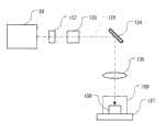
图12是构成本发明加工结构的高分子晶体加工设备的轮廓简图;Fig. 12 is a schematic outline diagram of the polymer crystal processing equipment constituting the processing structure of the present invention;
图13是构成本发明加工结构的高分子晶体加工设备与光学显微镜组合的状态简图。Fig. 13 is a schematic view of the combination of polymer crystal processing equipment and an optical microscope constituting the processing structure of the present invention.
本发明的最佳执行模式BEST MODE FOR CARRYING OUT THE INVENTION
下面将参考附图描述本发明的加工结构。图1表示构成本发明第一加工结构的激光器装置;该简图表示一种将固体激光器发出的激光经过波长转换之后输出的装置。具体地说,该激光器装置由基波产生部分1和波长转换部分2构成。The processing structure of the present invention will be described below with reference to the drawings. Fig. 1 shows a laser device constituting the first processing structure of the present invention; the schematic diagram shows a device for outputting laser light emitted by a solid-state laser after wavelength conversion. Specifically, the laser device is composed of a fundamental
图2是基波产生部分1的结构简图。FIG. 2 is a schematic structural diagram of the fundamental
产生基波的激光源利用附加Er3+的光纤放大器,并且主要由参考光源部分3、EDF部分4和激励光源部分5构成。波长为1547nm的脉冲光从构成参考光源部分3的参考光源的DFB输出,并被EDF部分4放大。EDF部分4由三级即EDF1、EDF2和EDF3的EDF构成。激励光分别从激励光源5a、5b和5c供给这三级。来自EDF3的输出光输入到波长转换部分(后叙)。The laser source for generating the fundamental wave uses an additional Er3+ fiber amplifier, and is mainly composed of a reference light source part 3 , an EDF part 4 and an excitation light source part 5 . Pulsed light with a wavelength of 1547 nm is output from the DFB of the reference light source constituting the reference light source section 3 and amplified by the EDF section 4 . The EDF section 4 is composed of EDFs of three stages, EDF1, EDF2, and EDF3. Excitation light is supplied to these three stages from excitation light sources 5a, 5b, and 5c, respectively. The output light from EDF3 is input to a wavelength converting section (described later).
图3是表示波长转换部分2的结构简图。波长转换部分2对从基波产生部分1输出的波长为1547nm的激光进行波长转换。波长转换部分2设有多个波长转换装置,即后面的各个高阶谐波产生部分:即二倍波产生部分6、三倍波产生部分7、四倍波产生部分8、七倍波产生部分9和八倍波产生部分10。在各个高阶谐波产生部分之间设置用于向下一个高阶谐波产生部分传播高阶谐波的光学元件。FIG. 3 is a schematic diagram showing the structure of the wavelength converting section 2. As shown in FIG. The wavelength converting section 2 wavelength-converts the laser light having a wavelength of 1547 nm output from the fundamental
在此加工结构中,所有的各个高阶谐波产生部分采用非线性光学晶体。具体而言,用LiB3O5(LBO)晶体作为二倍波产生部分6、三倍波产生部分7和四倍波产生部分8,用β-BaB2O4(BBO)晶体作为七倍波产生部分9,用CsLiB6O10(CLBO)晶体作为八倍波产生部分10。二倍波产生部分6、三倍波产生部分7、四倍波产生部分8、七倍波产生部分9和八倍波产生部分10分别产生波长为773nm、516nm、387nm、221nm和193nm的光。In this processing structure, all the various high-order harmonic generation parts use nonlinear optical crystals. Specifically, LiB3O5 (LBO) crystal was used as the double
具体地说,波长为1547nm的入射激光被透镜L1聚焦并导致入射到二倍波产生部分6上。倍频光(二倍波)从二倍波产生部分6与所述基波一起输出。这些光束被透镜L2聚焦,进入三倍波产生部分7并在那儿合成。然后频率为基波三倍的光(即,三倍波)与基波和二倍波一起输出。这些波中,三倍波被二向色镜M1反射,然后通过透镜L3和L4并被反射镜M2反射,再通过二向色镜M3,然后与频率为基波四倍的光(四倍波;后叙)合成。该系统布置成使得透镜L3和L4将三倍波聚焦到七倍波产生部分9上。Specifically, incident laser light having a wavelength of 1547 nm is focused by lens L1 and caused to be incident on double
关于通过二向色镜M1的基波和二倍波,二倍波被二向色镜M4反射并再被透镜L5聚焦,以致于该波入射到四倍波产生部分8。然后,四倍波从四倍波产生部分8与二倍波一起输出。Regarding the fundamental wave and the double wave passing through the dichroic mirror M1 , the double wave is reflected by the dichroic mirror M4 and then focused by the lens L5 so that the wave is incident on the quadruple
如上所述,四倍波的波长为387nm,以致于该光为紫外光。因此,用合成石英玻璃作为透镜。但是,如同现有技术中所述,此玻璃易于受损;因此采用一种通过组合两个构成本发明加工结构的柱状透镜11a和11b构成的光学元件,该元件具有单透镜的效果。此光学元件设计成把从四倍波产生部分8输出的四倍波聚焦到七倍波产生部分9上。具体地说,四倍波被二向色镜M3反射,与上述的三倍波合成并输入到七倍波产生部分9中。因此,频率是基波七倍的光(即,七倍波)从七倍波产生部分9与三倍波和四倍波一起输出。As mentioned above, the wavelength of the quadruple wave is 387 nm, so that the light is ultraviolet light. Therefore, synthetic quartz glass is used as the lens. However, as described in the prior art, this glass is easily damaged; therefore, an optical element constructed by combining two
这些光束通过一种通过组合两个(构成本发明加工结构)的柱状透镜12a和12b构成的具有单透镜的效果的光学元件,并且输入到二向色镜M5中;该处只有七倍波被反射并输入到八倍波产生部分10中。组合两个柱状透镜12a和12b的光学元件设计成将该七倍波聚焦到八倍波产生部分10。These light beams pass through a kind of optical element with the effect of a single lens formed by combining two
透过二向色镜M4的基波通过由反射镜M6、M7、M8和透镜L6和L7组成的光学系统,并且还通过二向色镜M5;此波通过透镜L6和L7的作用聚焦到八倍波产生部分10上。因此,基波和七倍波输入到八倍波产生部分10中,并且输出频率为基波八倍的光(即,八倍波)以及基波和七倍波。The fundamental wave transmitted through dichroic mirror M4 passes through the optical system composed of mirrors M6, M7, M8 and lenses L6 and L7, and also passes through dichroic mirror M5; this wave is focused to eight Double
因而,在图2所示的波长转换部分2中,用普通透镜聚焦基波、二倍波和三倍波,并且用组合两个柱状透镜的光学元件聚焦四倍波和七倍波。Thus, in the wavelength conversion section 2 shown in FIG. 2, the fundamental, double, and triple waves are focused with an ordinary lens, and the quadruple and heptad waves are focused with an optical element combining two cylindrical lenses.
这些柱状透镜11a、11b、12a和12b分别由保持装置13a、13b、14a和14b保持;这些保持装置具有如下结构,即允许在这些透镜的各个母线方向驱动各个柱状透镜11a、11b、12a和12b。另外,各个柱状透镜11a、11b、12a和12b的母线方向垂直于光轴,而柱状透镜11a和11b的母线方向与柱状透镜12a和12b的母线方向彼此垂直。结果,组合柱状透镜11a和11b的光学系统和组合柱状透镜12a和12b的光学系统分别具有与球面透镜相同的光学效果。These
图4是柱状透镜11a和11b的设置实例简图。因为各个透镜都是柱状透镜,所以这些透镜的特征在于如下事实:即使透镜在母线方向移动,光轴也不移位。例如,在透镜的划伤变得显著的情况下,可以通过图中未示的移动机构例如配备有测微仪的平台将透镜在母线方向(箭头所示的方向)上移动并利用透镜的未使用部分而延长激光器装置的使用寿命。柱状透镜12a和12b也有类似的设置。Fig. 4 is a diagram showing an example of arrangement of the
另外,在上述加工结构中,用合成石英玻璃作为各个柱状透镜的材料;但这种设置也可以应用到在除合成石英玻璃以外的材料(如氟石)中类似的划伤成为问题的情形中。另外,在上述加工结构中,采用组合两个柱状透镜的光学元件;但也可以采用组合三个或更多个柱状透镜的光学元件。In addition, in the processing structure described above, synthetic quartz glass is used as the material of each lenticular lens; but this arrangement can also be applied in cases where similar scratches are a problem in materials other than synthetic quartz glass (such as fluorspar) . In addition, in the processing structure described above, an optical element combining two lenticular lenses is employed; however, an optical element combining three or more lenticular lenses may also be employed.
图5是表示本发明第二加工结构的波长转换部分2的简图。波长转换部分2中的波长转换方法和光学系统的结构及其自身效果与图3中所示的波长转换部分完全相同;因此,相同的构件标有相同的符号,并且省去对这些构件的描述。此加工结构与图3所示加工结构的不同之处在于增加了控制机构,该控制机构探测柱状透镜11a、11b、12a和12b衰退、以致于光透射率下降这一事实,并定位光轴区中各个柱状透镜的未使用部分。Fig. 5 is a schematic diagram showing the wavelength converting portion 2 of the second processing structure of the present invention. The wavelength conversion method and the structure of the optical system in the wavelength conversion part 2 and their own effects are exactly the same as the wavelength conversion part shown in Fig. 3; therefore, the same components are marked with the same symbols, and the description of these components is omitted . This processing structure differs from the processing structure shown in FIG. 3 in that a control mechanism is added, which detects the fact that the
具体地说,光学探测器15探测透过二向色镜M3的二倍波的强度。另外,光学探测器16探测透过二向色镜M5的三倍波和四倍波的强度。这些探测值输入到控制装置17中并与特定值比较。然后,当光学探测器15的输出落至特定值之下时,控制装置17向驱动器18发送指令,以致于保持装置13a和13b被驱动特定的距离,由此造成柱状透镜11a和11b的到目前为止还未被使用的部分开始被使用。类似地,当光学探测器16的输出落至特定值之下时,控制装置17向驱动器18发送指令,以致于保持装置14a和14b被驱动特定的距离,由此造成柱状透镜12a和12b的到目前为止还未被使用的部分开始被使用。可以用公知的方法如在电驱动台上承载各个保持装置来移动各个保持装置。Specifically, the optical detector 15 detects the intensity of the double wave transmitted through the dichroic mirror M3. In addition, the
另外,在此加工结构中,光探测器15探测的不是四倍波,光探测器16探测的不是七倍波。但是,应该想到因为当柱状透镜衰退时各个高阶波的光强以同样的方式减弱,所以这不是一个特别的问题。具体地说,在希望直接测量四倍波和七倍波的各自强度的情况下,也可以采用例如将棱镜设置在二向色镜M3和M5之后而将四倍波和七倍波分开并测量的方法。In addition, in this processing structure, what the photodetector 15 detects is not a quadruple wave, and what the
图6至图9是控制装置基本操作的流程图。将参考图6描述主算法,并参考图7~9描述此主算法中的各个具体处理算法。6 to 9 are flowcharts of the basic operation of the control device. The main algorithm will be described with reference to FIG. 6 , and each specific processing algorithm in this main algorithm will be described with reference to FIGS. 7 to 9 .
在图6所示的主算法中,执行根据各个电驱动台的可能驱动范围内外的处理。首先,在步骤S1,执行对各个信号Sig1和Sig2以及各个标志Flag1和Flag2的初始化,信号Sig1和Sig2来自光探测器15和光探测器16,标志Flag1和Flag2用于探查四倍波透镜保持装置13a和13b和七倍波透镜保持装置14a和14b的可能驱动范围。这里,在Flag1和Flag2分别为0的情况下,表示保持装置处于可能的驱动范围之内。当这些标志为1时,表示保持装置处于驱动范围之外。In the main algorithm shown in FIG. 6 , processing according to the possible driving range of each electrically driven stage inside and outside is performed. First, in step S1, initialization of the respective signals Sig1 and Sig2 and the respective flags Flag1 and Flag2, the signals Sig1 and Sig2 coming from the photodetector 15 and the
接下来,在步骤S2,获得Flag1和Flag2的值。接下来,在步骤S3,探查所获Flag1和Flag2的条件。在Flag1和Flag2都为0的情况下,执行完处理1之后处理返回到S2。在只有Flag1为1的情况下,执行完处理2之后处理返回到S2。在只有Flag2为1的情况下,执行完处理3之后处理返回到S2。在Flag1和Flag2都为1的情况下,执行完处理4之后结束处理。Next, in step S2, the values of Flag1 and Flag2 are obtained. Next, in step S3, the conditions of the obtained Flag1 and Flag2 are checked. When both Flag1 and Flag2 are 0, the process returns to S2 after the
在图6所示处理1的算法中(图7所示),对来自各个探测器15和16的信号值Sig1和Sig2与预先储存的值Ref1和Ref2进行比较;另外,探查这些值是否处于可能的驱动范围之内或之外,并且根据获得的结果执行各个电驱动台的驱动或非驱动。In the algorithm of
首先,在步骤S11,获得Sig1和Sig2的值。接下来,在步骤S12,比较Sig1与预先储存的设置值Ref1。在Sig1<Ref1的情况下,探查在步骤S13中是否该值处于可能的驱动范围之内或之外。如果该值处于可能的驱动范围之内,则在步骤S14中将四倍波透镜保持装置13a和13b移动特定的距离;移动透镜之后,结束处理。如果该值处于可能的驱动范围之外,则在步骤S15中设置Flag1=1并结束处理。First, in step S11, the values of Sig1 and Sig2 are obtained. Next, in step S12, Sig1 is compared with the pre-stored setting value Ref1. In the case of Sig1<Ref1, it is checked in step S13 whether the value lies within or outside the possible driving range. If the value is within the possible driving range, the quadruple-wave
在步骤S12中Sig1不小于Ref1的情况下,在步骤S16中比较Sig2与预先储存的设置值Ref2。在Sig2<Ref2的情况下,在步骤S17中探查该值是否在可能的驱动范围内。如果该值处于可能的驱动范围内,则在步骤S18中七倍波透镜保持装置14a和14b移动特定的距离;透镜移动之后,结束处理。在该值处于可能的驱动范围之外的情况下,在步骤S19中设置Flag2=1,并且结束处理。在步骤S16中Sig2不小于Ref2的情况下,同样结束处理。In the case that Sig1 is not smaller than Ref1 in step S12, Sig2 is compared with the pre-stored setting value Ref2 in step S16. In the case of Sig2<Ref2, it is checked in step S17 whether this value is within the possible driving range. If the value is within the possible driving range, the sevenfold wave
在图8所示处理2的算法中,比较来自光探测器16的信号值与预先储存的值,并且探查该值是否处于可能的驱动范围之内或之外。根据结果执行七倍波透镜保持装置14a和14b的驱动或非驱动。In the algorithm of process 2 shown in Figure 8, the signal value from the
首先,在步骤S21中获得Sig2的值。接下来,在步骤S22中比较Sig2与预先储存的设置值Ref2。在Sig2<Ref2的情况下,在步骤S23中探查该值是否处于可能的驱动范围之内。如果该值处于可能的驱动范围之内,则在步骤S24中将七倍波透镜保持装置14a和14b移动特定的距离;在移动透镜之后,结束处理。在该值处于可能的驱动范围之外的情况下,在步骤S25中设置Flag2=1,并且结束处理。在步骤S22中Sig2不小于Ref2的情况下,同样结束处理。First, the value of Sig2 is obtained in step S21. Next, compare Sig2 with the pre-stored setting value Ref2 in step S22. In the case of Sig2<Ref2, it is checked in step S23 whether this value is within the possible driving range. If the value is within the possible driving range, the seven-fold
在图9所示的处理3的算法中,比较来自光探测器15的信号值与预先储存的值,并且探查该值是否处于可能的驱动范围之内或之外。根据所得的结果执行四倍波透镜保持装置13a和13b的驱动或非驱动。In the algorithm of process 3 shown in Fig. 9, the signal value from the photodetector 15 is compared with a pre-stored value and it is checked whether the value is within or outside the possible driving range. Driving or non-driving of the quadruple-wave
首先,在步骤S31中,获得Sig1的值。接下来,在步骤S32中,比较Sig1与预先储存的设置值Ref1。在Sig1<Ref1的情况下,在步骤S33中探查该值是否在可能的驱动范围内。如果该值处于可能的驱动范围内,则在步骤S34中驱动四倍波透镜保持装置13a和13b;透镜移动之后,结束处理。在该值处于可能的驱动范围之外的情况下,在步骤S35中设置Flag1=1,并且结束处理。在步骤S32中Sig1不小于Ref1的情况下,同样结束处理。First, in step S31, the value of Sig1 is obtained. Next, in step S32, Sig1 is compared with the pre-stored setting value Ref1. In the case of Sig1<Ref1, it is checked in step S33 whether this value is within the possible driving range. If the value is within the possible driving range, the quadruple-wave
在处理4中,因为四倍波透镜保持装置13a和13b以及七倍波透镜保持装置14a和14b均在此时处于可能的驱动范围之外,则通知该信息并结束主算法。In Process 4, since both the quadruple-wave
在上述加工结构中,该系统布置成使得当来自光探测器15和16的输出落至约定值之下时移动柱状透镜。但是,也可以将该系统布置成使得柱状透镜根据设备使用的时间来移动。例如,可以把该系统设计成使得控制装置17通过探测来自光探测器15和16的输出来探查正被使用的设备,并且使柱状透镜在每次累计使用时间达到特定时间时移动特定的距离。另外,该系统也可以设计成使得以柱状透镜的移动量正比于设备的累计使用时间的方式实施位置控制。In the processing configuration described above, the system is arranged so that the lenticular lens is moved when the outputs from the
接下来,参考图10描述曝光设备100,该曝光设备100利用激光器装置20(以下也称作“激光器装置”)构成并用在组成一个半导体制作过程的光刻过程中,其中激光器装置20由上述基波产生部分1和波长转换部分2构成。就操作原理来说,用在光刻过程中的曝光设备与用在照相底板制作中的设备一样;在此设备中,精确描绘在光掩模(分划板)上的器件图案通过光学投影转印到涂覆有光致抗蚀剂的半导体晶片、玻璃衬底等上。此曝光设备100构造成使得此设备包括上述的激光器装置20、照明光学系统102、支撑光掩模(分划板)110的掩模支撑台103、投影光学系统104、承载并保持构成曝光对象的半导体晶片115的承载台105、和促使承载台105在水平方向移动的驱动设备106。Next, an
在此曝光设备100中,从上述激光器装置20输出的激光输入到由多个透镜构成的照明光学系统102中,并且支撑在掩模支撑台103上的光掩模110的整个表面通过该照明光学系统照明。作为此照明的结果,透过光掩模110的光含有描绘在光掩模110上的器件图案的图像;此光对承载在承载台105上的半导体晶片115上的特定位置进行照明(该照明通过投影光学系统104完成)。在此情况下,投影光学系统104将光掩模110上器件图案的图像缩小并聚焦为在半导体晶片115上的图像,从而使晶片曝光。In this
另外,曝光设备中照明光量的控制例如可以很容易地通过控制参考光源部分3中的脉冲频率或控制激励光源部分5中激励光的输出来实现。而且,激光的开关控制可以通过参考光源部分3中DFB半导体激光器的开关控制来实现;或者,这种控制可以很容易地通过在光路上安装调制元件如电光调制元件和声光调制元件或安装机械开关来实现。因此,在上述曝光设备中,可以利用具有较高设置自由度的紫外光源的袖珍、质轻等特点获得具有良好的维护特性和操作特性的袖珍曝光设备。In addition, the control of the amount of illumination light in the exposure apparatus can be easily realized by controlling the pulse frequency in the reference light source section 3 or controlling the output of excitation light in the excitation light source section 5, for example. Moreover, the switch control of the laser can be realized by referring to the switch control of the DFB semiconductor laser in the light source part 3; or, this control can be easily achieved by installing a modulation element such as an electro-optic modulation element and an acousto-optic modulation element or installing a mechanical switch to achieve. Therefore, in the above-mentioned exposure equipment, it is possible to obtain a pocket-sized exposure equipment with good maintenance characteristics and operation characteristics by utilizing the characteristics of the ultraviolet light source having a high degree of freedom of arrangement such as being small and light.
在本发明的紫外光源中,如上所述,单模光纤激光器用作光纤放大器的激励光源;因此,可以利用简单的设备结构提供一种实现高峰值功率和高平均输出的紫外光源。In the ultraviolet light source of the present invention, as described above, a single-mode fiber laser is used as an excitation light source for a fiber amplifier; therefore, an ultraviolet light source realizing high peak power and high average output can be provided with a simple device structure.
接下来,下面将参考图11描述利用上述本发明激光器装置20构成的掩模缺陷检测装置。此掩模检测装置把精确描绘在光掩模上的器件图案光学投影到TDI传感器(时间延迟和积分)上,比较传感器图像与特定的参考图像,并且从差异中提取图案缺陷。掩模缺陷检测装置120构造成使得该装置包括上述的激光器装置20、照明光学系统112、支撑光掩模110的掩模支撑台113、在水平方向上驱动掩模支撑台的驱动设备116、投影光学系统114和TDI传感器125。在此掩模缺陷检测装置120中,从上述激光器装置20输出的激光入射到由多个透镜构成的照明光学系统112中,并穿过该系统,从而使得该光对支撑在掩模支撑台113上的光掩模110上的特定区域进行照明。作为此照明的结果,穿过光掩模110的光具有描绘在光掩模110上的器件图案的图像;此光通过投影光学系统114聚焦为在TDI传感器125上的特定位置上的图像。另外,掩模支撑台113的水平移动速度与TDI 125的平移时钟同步。Next, a mask defect inspection apparatus constructed using the
图12是利用本发明的激光器装置20构成的高分子晶体加工设备的简图。此处,从激光器装置20发出的紫外短脉冲激光139经过快门132、强度调节元件133、照明位置控制机构134和聚焦光学系统135聚焦并指向到放置在样品容器136内部的高分子晶体138上。样品容器136安置在平台137上,并布置成使得可以沿x-y-z正交坐标系中的x轴、y轴和z轴三维移动,其中光轴的方向取作z轴,并且使得还可以绕z轴转动。高分子晶体的加工通过聚焦并指向到高分子晶体138表面上的激光执行。FIG. 12 is a schematic diagram of a polymer crystal processing facility constructed using the
顺便说一下,在加工由高分子晶体组成的加工对象的情况下,需要确认加工对象上由激光照明的位置。但是,因为激光通常不是可见光,所以视觉检测不可能;因此,希望与光学显微镜组合使用。Incidentally, in the case of processing a processing object composed of polymer crystals, it is necessary to confirm the position on the processing object illuminated by the laser light. However, since laser light is generally not visible light, visual inspection is not possible; therefore, it is desirable to use it in combination with an optical microscope.
图13表示此例。在图13(a)所示的光学系统中,来自紫外短脉冲激光器系统141的激光(对应于图12中的符号20和132~134)经聚焦光学系统135聚焦到特定点。平台137具有图12所示的功能;容纳高分子晶体138的样品容器136放置在平台137上。来自照明光源142的可见光被反射镜143反射,并对样品容器136进行科勒照明。高分子晶体138由人眼146通过光学显微镜的物镜144和目镜145视觉检测。Figure 13 shows this example. In the optical system shown in FIG. 13( a ), laser light from an ultraviolet short pulse laser system 141 (corresponding to
在光学显微镜的光轴位置上形成十字形标记,以致于可以通过视觉检测来检测光轴的位置。另外,光学显微镜的焦点位置(聚焦位置,即视觉检测期间形成焦点的对象平面)固定。该系统设计成使得被聚焦光学系统135聚焦的激光聚焦在光学显微镜的光轴位置上,并且也在光学显微镜的焦点位置上。因此,在加工对象放置在平台137上的情况下,用光学显微镜观察此加工对象的图像,图像处于焦点处,并且该系统布置成使得来自激光器系统141的激光聚焦在十字形标记的中心位置处。另外,激光器系统141、聚焦光学系统135和光学显微镜的相对位置关系固定;使得只有平台137可相对于这些固定系统移动。A cross-shaped mark is formed on the position of the optical axis of the optical microscope so that the position of the optical axis can be detected by visual inspection. In addition, the focus position of the optical microscope (focus position, that is, the object plane that forms the focus during visual inspection) is fixed. The system is designed such that the laser light focused by the focusing
因此,可以通过在移动平台137的同时进行加工、使得进行加工比较理想的位置处于光学显微镜的光轴位置以及焦点位置,从而加工该理想位置并实现理想形状的加工。如果希望进行自动加工,这可以通过把自动焦点调节装置连接到光学显微镜、根据该自动焦点调节装置的指令驱动平台137、并执行平台137的驱动使得平台137的预定的特定部分位于光学显微镜的光轴上来实现。或者,也可以首先对齐参考位置,再通过伺服机构在二维方向或三维方向上驱动平台137。Therefore, by processing while moving the
Claims (18)
Applications Claiming Priority (2)
| Application Number | Priority Date | Filing Date | Title |
|---|---|---|---|
| JP2003079492 | 2003-03-24 | ||
| JP079492/2003 | 2003-03-24 |
Publications (2)
| Publication Number | Publication Date |
|---|---|
| CN1761907A CN1761907A (en) | 2006-04-19 |
| CN100427994Ctrue CN100427994C (en) | 2008-10-22 |
Family
ID=33094844
Family Applications (1)
| Application Number | Title | Priority Date | Filing Date |
|---|---|---|---|
| CNB2004800076236AExpired - Fee RelatedCN100427994C (en) | 2003-03-24 | 2004-03-22 | Optical element, optical system, laser device, exposure apparatus, mask inspection apparatus, and polymer crystal processing apparatus |
Country Status (6)
| Country | Link |
|---|---|
| US (1) | US7379251B2 (en) |
| EP (1) | EP1615067B1 (en) |
| JP (1) | JP4862398B2 (en) |
| KR (1) | KR20060014359A (en) |
| CN (1) | CN100427994C (en) |
| WO (1) | WO2004086121A1 (en) |
Families Citing this family (12)
| Publication number | Priority date | Publication date | Assignee | Title |
|---|---|---|---|---|
| WO2005026238A1 (en)* | 2003-09-11 | 2005-03-24 | Nikon Corporation | Processing method of polymer crystal, processing system of polymer crystal, and observation system of polymer crystal |
| JP4739188B2 (en) | 2004-03-31 | 2011-08-03 | 株式会社ニコン | Organic crystal processing method, organic crystal processing apparatus, and organic crystal observation apparatus |
| JP5446263B2 (en) | 2006-07-20 | 2014-03-19 | 株式会社ニコン | Optical fiber amplifier, light source device, exposure device, inspection object inspection device, and processing device |
| US20100253769A1 (en)* | 2008-09-04 | 2010-10-07 | Laser Light Engines | Optical System and Assembly Method |
| US10678061B2 (en) | 2009-09-03 | 2020-06-09 | Laser Light Engines, Inc. | Low etendue illumination |
| US9503606B2 (en) | 2011-09-28 | 2016-11-22 | Semiconductor Components Industries, Llc | Time-delay-and-integrate image sensors having variable integration times |
| KR20200030633A (en)* | 2012-07-31 | 2020-03-20 | 가부시키가이샤 니콘 | Laser device, and exposure device and inspection device equipped with said laser device |
| US9608399B2 (en)* | 2013-03-18 | 2017-03-28 | Kla-Tencor Corporation | 193 nm laser and an inspection system using a 193 nm laser |
| JPWO2015029141A1 (en)* | 2013-08-27 | 2017-03-02 | 三菱電機株式会社 | Laser oscillator |
| JP6268949B2 (en)* | 2013-11-07 | 2018-01-31 | セイコーエプソン株式会社 | Light source device and projector |
| KR101771885B1 (en)* | 2014-11-06 | 2017-08-25 | 미쓰비시덴키 가부시키가이샤 | Laser machining method and device |
| CN104759753B (en)* | 2015-03-30 | 2016-08-31 | 江苏大学 | The co-ordination of multisystem automatization improves the method for induced with laser cavitation reinforcement |
Citations (3)
| Publication number | Priority date | Publication date | Assignee | Title |
|---|---|---|---|---|
| JPH0750442A (en)* | 1993-08-05 | 1995-02-21 | Hoya Corp | Laser equipment for processing |
| US5912725A (en)* | 1995-06-23 | 1999-06-15 | Nikon Corporation | Illumination optical system to be used in an exposure apparatus and a method of manufacturing a semiconductor structure using the exposure apparatus |
| CN1256536A (en)* | 1998-12-10 | 2000-06-14 | 山西大学 | Single-frequency frequency-doubling solid laser |
Family Cites Families (12)
| Publication number | Priority date | Publication date | Assignee | Title |
|---|---|---|---|---|
| US4733944A (en)* | 1986-01-24 | 1988-03-29 | Xmr, Inc. | Optical beam integration system |
| US5150151A (en) | 1989-03-09 | 1992-09-22 | Canon Kabushiki Kaisha | Reflecting device and pattern transfer apparatus using the same |
| US5016964A (en)* | 1989-10-04 | 1991-05-21 | Spectranetics Corporation | Optical fiber coupler with linear input |
| JPH0728226A (en) | 1993-04-30 | 1995-01-31 | Internatl Business Mach Corp <Ibm> | Equipment and method for measuring regional image |
| DE19612710A1 (en) | 1996-03-29 | 1997-10-02 | Sick Ag | Light spot generating device |
| JP4032446B2 (en) | 1996-12-12 | 2008-01-16 | ソニー株式会社 | Video data compression apparatus and method |
| WO1999046835A1 (en) | 1998-03-11 | 1999-09-16 | Nikon Corporation | Ultraviolet laser apparatus and exposure apparatus comprising the ultraviolet laser apparatus |
| JP4232130B2 (en)* | 1998-03-11 | 2009-03-04 | 株式会社ニコン | Laser apparatus and light irradiation apparatus and exposure method using this laser apparatus |
| JP2001353176A (en) | 2000-04-13 | 2001-12-25 | Nikon Corp | Laser therapy equipment |
| DE19855106A1 (en)* | 1998-11-30 | 2000-05-31 | Zeiss Carl Fa | Illumination system for VUV microlithography |
| JP2002086938A (en)* | 2000-09-18 | 2002-03-26 | Konica Corp | Laser heat transfer film |
| US6596967B2 (en)* | 2000-10-24 | 2003-07-22 | Edward Miesak | Laser based etching device |
- 2004
- 2004-03-22EPEP04722409.2Apatent/EP1615067B1/ennot_activeExpired - Lifetime
- 2004-03-22KRKR1020057010962Apatent/KR20060014359A/ennot_activeCeased
- 2004-03-22CNCNB2004800076236Apatent/CN100427994C/ennot_activeExpired - Fee Related
- 2004-03-22WOPCT/JP2004/003820patent/WO2004086121A1/enactiveApplication Filing
- 2004-03-22JPJP2005504034Apatent/JP4862398B2/ennot_activeExpired - Fee Related
- 2005
- 2005-09-14USUS11/226,742patent/US7379251B2/ennot_activeExpired - Lifetime
Patent Citations (3)
| Publication number | Priority date | Publication date | Assignee | Title |
|---|---|---|---|---|
| JPH0750442A (en)* | 1993-08-05 | 1995-02-21 | Hoya Corp | Laser equipment for processing |
| US5912725A (en)* | 1995-06-23 | 1999-06-15 | Nikon Corporation | Illumination optical system to be used in an exposure apparatus and a method of manufacturing a semiconductor structure using the exposure apparatus |
| CN1256536A (en)* | 1998-12-10 | 2000-06-14 | 山西大学 | Single-frequency frequency-doubling solid laser |
Also Published As
| Publication number | Publication date |
|---|---|
| US20060078012A1 (en) | 2006-04-13 |
| EP1615067A4 (en) | 2008-09-17 |
| WO2004086121A1 (en) | 2004-10-07 |
| CN1761907A (en) | 2006-04-19 |
| EP1615067A1 (en) | 2006-01-11 |
| JP4862398B2 (en) | 2012-01-25 |
| US7379251B2 (en) | 2008-05-27 |
| EP1615067B1 (en) | 2015-09-23 |
| JPWO2004086121A1 (en) | 2006-06-29 |
| KR20060014359A (en) | 2006-02-15 |
Similar Documents
| Publication | Publication Date | Title |
|---|---|---|
| JP6626997B2 (en) | Inspection system | |
| US7623557B2 (en) | Wavelength converting optical system, laser light source, exposure apparatus, mask examining apparatus, and macromolecular crystal lens machining device | |
| CN100427994C (en) | Optical element, optical system, laser device, exposure apparatus, mask inspection apparatus, and polymer crystal processing apparatus | |
| US7339961B2 (en) | Wavelength converting optical system, laser light source, exposure apparatus, device for inspecting object of inspection, and polymer crystal working apparatus | |
| JP6279565B2 (en) | Projection exposure apparatus for projection lithography | |
| JP6016086B2 (en) | Ultraviolet laser apparatus, exposure apparatus and inspection apparatus equipped with the ultraviolet laser apparatus | |
| KR20150016584A (en) | Solid-state laser and inspection system using 193nm laser | |
| JPH10341054A (en) | Ultraviolet laser device and semiconductor aligner | |
| US7397598B2 (en) | Light source unit and light irradiation unit | |
| KR101618392B1 (en) | Laser apparatus, phototherapy apparatus, exposure apparatus, device manufacturing method, and object inspection apparatus | |
| JP2004086193A (en) | Light source device and light irradiation device | |
| JP2001083472A (en) | Light modulation device, light source device, and exposure device | |
| JP2024038283A (en) | Metrology to improve DUV laser alignment | |
| JP2007279084A (en) | Wavelength conversion optical system, laser light source, exposure apparatus, specimen inspection apparatus, and polymer crystal processing apparatus | |
| JP2003161974A (en) | Light source device and light irradiation device | |
| JP2013044764A (en) | Laser device, method for suppressing photorefractive effect of quasi-phase-matching wavelength conversion optical element, exposure device, and inspection device | |
| JP2011099941A (en) | Wavelength conversion element, optical system for wavelength conversion, wavelength conversion method, light source apparatus, exposure apparatus, apparatus for inspecting mask and apparatus for processing polymer crystal | |
| JP2005326522A (en) | Polarization beam splitter, light separation device, exposure device, laser device, mask inspection device, and polymer crystal processing device | |
| KR101187610B1 (en) | Wavelength conversion optical system, laser light source, exposure apparatus, object inspection device, and polymer crystal processing apparatus | |
| JP2006308908A (en) | DUV light source apparatus and laser processing apparatus | |
| JP2002261361A (en) | Optical amplification device, light source device, and light irradiation device | |
| JP2005109117A (en) | Projection optical system inspection method, inspection apparatus, and projection optical system manufacturing method | |
| JP2005351919A (en) | Wavelength conversion optical system, laser device, and mask defect inspection device | |
| JP2007005541A (en) | Projection optical system inspection apparatus and projection optical system manufacturing method |
Legal Events
| Date | Code | Title | Description |
|---|---|---|---|
| C06 | Publication | ||
| PB01 | Publication | ||
| C10 | Entry into substantive examination | ||
| SE01 | Entry into force of request for substantive examination | ||
| C14 | Grant of patent or utility model | ||
| GR01 | Patent grant | ||
| CF01 | Termination of patent right due to non-payment of annual fee | ||
| CF01 | Termination of patent right due to non-payment of annual fee | Granted publication date:20081022 |