CN100426010C - Light conducting plate and backlight module using the same - Google Patents
Light conducting plate and backlight module using the sameDownload PDFInfo
- Publication number
- CN100426010C CN100426010CCNB021521786ACN02152178ACN100426010CCN 100426010 CCN100426010 CCN 100426010CCN B021521786 ACNB021521786 ACN B021521786ACN 02152178 ACN02152178 ACN 02152178ACN 100426010 CCN100426010 CCN 100426010C
- Authority
- CN
- China
- Prior art keywords
- guide plate
- light guide
- light
- backlight module
- protrusions
- Prior art date
- Legal status (The legal status is an assumption and is not a legal conclusion. Google has not performed a legal analysis and makes no representation as to the accuracy of the status listed.)
- Expired - Fee Related
Links
Images


Landscapes
- Light Guides In General And Applications Therefor (AREA)
- Planar Illumination Modules (AREA)
Abstract
Description
Translated fromChinese【技术领域】【Technical field】
本发明涉及一种背光模块及其导光板,尤指一种出光辉度较高的导光板及采用该导光板的背光模块。The invention relates to a backlight module and a light guide plate thereof, in particular to a light guide plate with high luminance and a backlight module using the light guide plate.
【背景技术】【Background technique】
由于液晶显示装置具轻、薄、耗电小等优点,广泛应用于笔记本计算机、行动电话、个人数字助理等现代化信息设备。因液晶本身不具发光特性,需为其提供背光模块以实现显示功能。Due to the advantages of lightness, thinness, and low power consumption, liquid crystal display devices are widely used in modern information equipment such as notebook computers, mobile phones, and personal digital assistants. Since the liquid crystal itself does not have light-emitting properties, it is necessary to provide a backlight module for it to realize the display function.
现有技术背光模块包括光源及导光板,光源相对导光板的入光面设置,该导光板引导自光源发出光束的传输方向,将线光源或点光源转换成面光源出射。该导光板的底面分布多个网点,用以破坏光束于导光板内部传输的全反射条件,且使其散射以提高导光板出射光束的均匀性,进而提升背光模块的整体性能。该网点的疏密、大小均可有不同设计以适应不同的背光模块。The prior art backlight module includes a light source and a light guide plate. The light source is arranged relative to the light incident surface of the light guide plate. The light guide plate guides the transmission direction of the light beam emitted from the light source, and converts the line light source or point light source into a surface light source to emit. A plurality of dots are distributed on the bottom surface of the light guide plate to destroy the total reflection condition of light beams transmitted inside the light guide plate and scatter them to improve the uniformity of the light beams emitted by the light guide plate, thereby improving the overall performance of the backlight module. The density and size of the dots can be designed in different ways to suit different backlight modules.
一种现有技术背光模块可参阅2002年9月3日公告的美国专利第6,443,583号(图1参照),该背光模块100包括一灯管110、一围绕灯管110的灯罩120及一端部固持于灯罩120的导光板200。该导光板200包括入光面201、底面202及出光面203,其中,该灯管110相对该入光面201设置。工作时,来自灯管110及灯罩120的光束于该导光板200内部传输,并转换为面光源经出光面203出射。为增加光束的利用率,该背光模块100进一步包括一设置于导光板200的底面202一侧的反射板210以反射自底面202出射的部份光束。且该背光模块100于导光板200出光面203一侧依序排列一扩散板220、第一棱镜板230及第二棱镜板240,该扩散板220用以增强导光板200出射光束的均匀度,二棱镜板230及240则起聚光作用,以增强导光板200的辉度。A prior art backlight module can refer to US Patent No. 6,443,583 published on September 3, 2002 (refer to FIG. 1 ). The
但是,该背光模块100需采用二棱镜板230及240以聚集自导光板200出光面203出射的光束以提高辉度,使其结构复杂、材料成本高且组装不便。此外,该背光模块100中存在较多光学接口,光束于其间需经历多次光学作用,造成较大的光学损耗,影响背光模块100的辉度。However, the
【发明内容】【Content of invention】
为解决现有技术导光板出光辉度较低、光学性能较差的第一技术问题,本发明提供一种出光辉度较高、光学性能优良的导光板。In order to solve the first technical problem of the prior art light guide plate with low luminance and poor optical performance, the present invention provides a light guide plate with high luminance and excellent optical performance.
为解决现有技术背光模块结构较复杂、组装不便、成本较高和光学性能较差的第二技术问题,本发明提供一种结构简单、组装便捷、成本低且光学性能优良的背光模块。In order to solve the second technical problem of the prior art backlight module with complex structure, inconvenient assembly, high cost and poor optical performance, the present invention provides a backlight module with simple structure, convenient assembly, low cost and excellent optical performance.
本发明解决第一技术问题所采用的技术方案是:提供一种导光板包括至少一用以接收光束的入射面、一与入射面相交且用以引导光束出射的出射面和一与出射面相对的底面。该底面分布有多个凸起,该多个凸起的散射面构成一曲面,且该底面及该多个凸起的散射面镀有反射膜。The technical solution adopted by the present invention to solve the first technical problem is to provide a light guide plate comprising at least one incident surface for receiving light beams, an exit surface intersecting with the incident surface and used for guiding light beams to exit, and an exit surface opposite to the exit surface. the underside. The bottom surface is distributed with a plurality of protrusions, the scattering surfaces of the plurality of protrusions form a curved surface, and the bottom surface and the scattering surfaces of the plurality of protrusions are coated with reflective film.
本发明解决第二技术问题所采用的技术方案是:提供一种背光模块包括至少一用以发出光束的光源及一用以接收光束的导光板。该导光板包括至少一用以接收光束的入射面、一与入射面相交且用以引导光束出射的出射面和一与出射面相对的底面。该底面分布有多个凸起,该多个凸起的散射面构成一曲面,且该底面及该多个凸起的散射面镀有反射膜。The technical solution adopted by the present invention to solve the second technical problem is to provide a backlight module comprising at least one light source for emitting light beams and a light guide plate for receiving light beams. The light guide plate includes at least one incident surface for receiving light beams, an outgoing surface intersecting with the incident surface and used for guiding light beams to exit, and a bottom surface opposite to the outgoing surface. The bottom surface is distributed with a plurality of protrusions, the scattering surfaces of the plurality of protrusions form a curved surface, and the bottom surface and the scattering surfaces of the plurality of protrusions are coated with reflective film.
相较于现有技术,本发明具有如下优点:因本发明导光板底面分布多个凸起,且该多个凸起的散射面形成一特定形状的曲面,可汇聚经凸起散射后的光束,且该底面及该多个凸起的散射面镀有反射膜,可反射光束至出射面,从而使得导光板出光辉度较高,且具一定的均匀性。本发明背光模块采用导光板及光源的组合,可不使用棱镜板或仅使用一棱镜板,其结构简单、成本较低,且光束的能量损耗较小。Compared with the prior art, the present invention has the following advantages: because the bottom surface of the light guide plate of the present invention is distributed with a plurality of protrusions, and the scattering surfaces of the plurality of protrusions form a curved surface of a specific shape, which can converge the light beams scattered by the protrusions , and the bottom surface and the scattering surfaces of the plurality of protrusions are coated with a reflective film, which can reflect light beams to the exit surface, so that the light output of the light guide plate has a higher luminance and a certain uniformity. The backlight module of the present invention adopts a combination of a light guide plate and a light source, and may not use a prism plate or only use a prism plate. The structure is simple, the cost is low, and the energy loss of the light beam is small.
【附图说明】【Description of drawings】
图1是现有技术背光模块的剖视图。FIG. 1 is a cross-sectional view of a prior art backlight module.
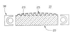
图2是本发明背光模块第一实施方式的立体图。FIG. 2 is a perspective view of the first embodiment of the backlight module of the present invention.
图3是图2所示背光模块沿III-III方向的剖视图。FIG. 3 is a cross-sectional view of the backlight module shown in FIG. 2 along the direction III-III.
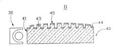
图4是本发明背光模块第二实施方式的立体图。FIG. 4 is a perspective view of the second embodiment of the backlight module of the present invention.
图5是图4所示背光模块沿V-V方向的剖视图。FIG. 5 is a cross-sectional view of the backlight module shown in FIG. 4 along the V-V direction.
图6是本发明背光模块第三实施方式的立体图。FIG. 6 is a perspective view of a third embodiment of the backlight module of the present invention.
图7是图6所示背光模块沿VII-VII方向的剖视图。FIG. 7 is a cross-sectional view of the backlight module shown in FIG. 6 along VII-VII direction.
图8是本发明背光模块第四实施方式的剖视图。FIG. 8 is a cross-sectional view of a fourth embodiment of a backlight module of the present invention.
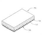
图9是本发明导光板另一实施方式的局部剖视图。Fig. 9 is a partial cross-sectional view of another embodiment of the light guide plate of the present invention.
【具体实施方式】【Detailed ways】
请参阅图2,本发明背光模块第一实施方式,该背光模块10包括一导光板20及二光源30。该导光板20包括二入射面21、一与入射面21相连的出射面22及一与出射面22相对的底面24。该光源30包括一灯管31及一部份围绕灯管31的反射罩32。该二光源30分别相对该导光板20的二入射面21设置。Please refer to FIG. 2 , which shows the first embodiment of the backlight module of the present invention. The
请一起参阅图2及图3,该导光板20的底面24分布多个凸起23。该多个凸起23用以使光束散射,破坏自入射面21进入的光束于导光板20内部传输的全反射条件,且提高自出射面22出射的光束的辉度及均匀性。该多个凸起23均匀分布于该导光板20的底面24,其为矩形状,亦可为圆柱状、圆台状、球状或立方体。该多个凸起23的散射面25形成一曲面,该曲面是部分圆柱面,用以汇聚经凸起23散射的光束,进而增强出射面22出射光束的辉度。该导光板20的底面24及凸起23的散射面25具有反射膜(未标示),该反射膜由SiO2与TiO2交替形成的多层薄膜,使投射于其上的光束反射,以防止光束自导光板20的底面24及凸起23的散射面25逸出,从而降低光束的能量损耗,提高导光板20的整体光学性能。该反射膜可采用化学气相沉积法、电子束蒸镀法、溅镀法等方法形成,其在可见光区的反射率可达98%以上。Please refer to FIG. 2 and FIG. 3 together. A plurality of
相较现有技术,由于本发明导光板20的底面24分布多个凸起23,且凸起23的散射面25形成一特定形状的曲面,可汇聚经凸起23散射的光束,从而使得导光板20出光辉度较高,且具一定的均匀性。本发明背光模块10采用导光板20及光源30的组合,其结构简单、成本较低,且光束的能量损耗较小。Compared with the prior art, since the
请参阅图4及图5,本发明背光模块第二实施方式,该背光模块11包括一光源30及一导光板40。该导光板40包括一入射面41及一与入射面41相交的底面44,该光源30可为线光源(如冷阴极萤光灯管)或点光源(如发光二极管),其相对入射面41设置。该底面44分布多个凸起43,该凸起43的散射面45形成一曲面,该曲面是部分圆柱面,用以汇聚经凸起43散射的光束。该凸起43的大小及密度沿远离入射面41的方向逐渐增加,用以改善导光板40及背光模块11出射光束的均匀性。该底面44凸起43的散射面45具有反射膜(未标示),该反射膜由SiO2与TiO2交替形成的多层薄膜。Please refer to FIG. 4 and FIG. 5 , the second embodiment of the backlight module of the present invention, the
请参阅图6及图7,本发明背光模块第三实施方式。该背光模块12包括一光源30及一导光板60。该导光板60一楔形导光板,其包括一入射面61及一与入射面61倾斜相连的底面64,该光源30相对该入射面61设置。该底面64分布多个凸起63。该多个凸起63均匀分布于该导光板60的底面64,其为立方体,亦可为圆柱状、圆台状、球状或矩形状。该多个凸起63的散射面65形成一曲面,该曲面是部分圆柱面,用以汇聚经凸起63散射的光束,进而增强导光板60出射光束的辉度。该导光板60的底面64凸起63的散射面65具有反射膜(未标示),以防止光束自导光板60的底面64逸出,从而降低光束的能量损耗,提高导光板60的整体光学性能。Please refer to FIG. 6 and FIG. 7 , the third embodiment of the backlight module of the present invention. The
请参阅图8,本发明背光模块第四实施方式。该背光模块13包括一光源30及一导光板70。该导光板70一楔形导光板,其包括一入射面(未标示)及一与入射面倾斜相连的底面74,该光源30相对该入射面设置。该底面74分布多个凸起73。该多个凸起73均匀分布于该导光板70的底面74,其为立方体,亦可为圆柱状、圆台状、球状或矩形状。该多个凸起73的散射面75形成一曲面,该曲面是部分圆柱面,用以汇聚经凸起73散射的光束,进而增强导光板70出射光束的辉度。该导光板70的底面74凸起73的散射面75具有反射膜(未标示),以防止光束自导光板70的底面74逸出,从而降低光束的能量损耗,提高导光板70的整体光学性能。为进一步增强背光模块1 3出射光束辉度的均匀性,于导光板70的出射面72一侧设置一扩散板80,为进一步汇聚经扩散板80散射的光束,提高背光模块13的出光辉度,可于扩散板80与出射面72相邻一侧的另一侧设置一棱镜板90.Please refer to FIG. 8 , the fourth embodiment of the backlight module of the present invention. The
请参阅图9,本发明导光板的另一实施方式。该导光板50与第二图所示导光板20的结构大致相同,其包括一底面54,该底面54分布多个凸起53.该多个凸起53均匀分布于该导光板50的底面54,其为矩形状,亦可为圆柱状、圆台状、球状或立方体。该多个凸起53的散射面55形成一曲面,该曲面是圆弧面,用以汇聚经凸起53散射的光束,进而增强导光板50出射光束的辉度.该导光板50的底面54凸起53的散射面55具有反射膜(未标示),以防止光束自导光板50的底面54凸起53的散射面55逸出,从而降低光束的能量损耗,提高导光板50的整体光学性能。Please refer to FIG. 9 , another embodiment of the light guide plate of the present invention. The structure of the
Claims (10)
Priority Applications (1)
| Application Number | Priority Date | Filing Date | Title |
|---|---|---|---|
| CNB021521786ACN100426010C (en) | 2002-12-02 | 2002-12-02 | Light conducting plate and backlight module using the same |
Applications Claiming Priority (1)
| Application Number | Priority Date | Filing Date | Title |
|---|---|---|---|
| CNB021521786ACN100426010C (en) | 2002-12-02 | 2002-12-02 | Light conducting plate and backlight module using the same |
Publications (2)
| Publication Number | Publication Date |
|---|---|
| CN1504771A CN1504771A (en) | 2004-06-16 |
| CN100426010Ctrue CN100426010C (en) | 2008-10-15 |
Family
ID=34234665
Family Applications (1)
| Application Number | Title | Priority Date | Filing Date |
|---|---|---|---|
| CNB021521786AExpired - Fee RelatedCN100426010C (en) | 2002-12-02 | 2002-12-02 | Light conducting plate and backlight module using the same |
Country Status (1)
| Country | Link |
|---|---|
| CN (1) | CN100426010C (en) |
Families Citing this family (5)
| Publication number | Priority date | Publication date | Assignee | Title |
|---|---|---|---|---|
| CN101261398B (en)* | 2007-03-08 | 2011-05-18 | 苏州璨宇光学有限公司 | Backlight module |
| CN102374390B (en)* | 2010-08-09 | 2014-05-07 | 东莞万士达液晶显示器有限公司 | Columnar light-emitting module |
| CN102606952B (en)* | 2012-03-06 | 2014-10-15 | 深圳市华星光电技术有限公司 | Reflective incidence backlight module and liquid crystal display device |
| JP5621015B1 (en)* | 2013-05-31 | 2014-11-05 | シャープ株式会社 | Light guide plate, illumination device, display device, and television receiver |
| CN106838728B (en)* | 2017-03-16 | 2019-12-24 | 漳州立达信光电子科技有限公司 | A LED panel light |
Citations (4)
| Publication number | Priority date | Publication date | Assignee | Title |
|---|---|---|---|---|
| US5961198A (en)* | 1996-02-02 | 1999-10-05 | Hitachi, Ltd. | Liquid crystal display device and method of manufacturing backlighting light guide panel therefor |
| JPH11306833A (en)* | 1998-04-20 | 1999-11-05 | Mitsubishi Chemical Corp | Surface lighting device |
| CN1296604A (en)* | 1999-03-02 | 2001-05-23 | 松下电器产业株式会社 | Illuminating device and display device provided with the device |
| US6247826B1 (en)* | 1997-07-07 | 2001-06-19 | Seiko Epson Corporation | Illumination device and bulletin board device |
- 2002
- 2002-12-02CNCNB021521786Apatent/CN100426010C/ennot_activeExpired - Fee Related
Patent Citations (4)
| Publication number | Priority date | Publication date | Assignee | Title |
|---|---|---|---|---|
| US5961198A (en)* | 1996-02-02 | 1999-10-05 | Hitachi, Ltd. | Liquid crystal display device and method of manufacturing backlighting light guide panel therefor |
| US6247826B1 (en)* | 1997-07-07 | 2001-06-19 | Seiko Epson Corporation | Illumination device and bulletin board device |
| JPH11306833A (en)* | 1998-04-20 | 1999-11-05 | Mitsubishi Chemical Corp | Surface lighting device |
| CN1296604A (en)* | 1999-03-02 | 2001-05-23 | 松下电器产业株式会社 | Illuminating device and display device provided with the device |
Also Published As
| Publication number | Publication date |
|---|---|
| CN1504771A (en) | 2004-06-16 |
Similar Documents
| Publication | Publication Date | Title |
|---|---|---|
| JP5193987B2 (en) | Light guide plate and backlight module | |
| CN1881023B (en) | Backlight module | |
| CN101382698B (en) | Backlight module unit | |
| CN101644415B (en) | Light guide plate and backlight module | |
| US20050264716A1 (en) | LED package and backlight assembly for LCD comprising the same | |
| TWI254172B (en) | Surface light module and liquid crystal display using the same | |
| CN100395623C (en) | Backlight module | |
| CN101191945B (en) | Backlight module group | |
| CN100426010C (en) | Light conducting plate and backlight module using the same | |
| CN100395627C (en) | Background light board | |
| CN100389350C (en) | light guide plate | |
| TW200916911A (en) | Backlight module | |
| CN100468164C (en) | Backlight module | |
| CN1318865C (en) | Light board and light source system | |
| CN100395610C (en) | light guide plate | |
| CN100426091C (en) | Backlight module and light conducting plate | |
| CN2594821Y (en) | Surface light source mould assembly | |
| CN100370335C (en) | light guide | |
| CN222671987U (en) | Light guide plate with uniform light emitting | |
| CN100462802C (en) | Backlight module and its light guide plate | |
| CN1249493C (en) | Light guide element | |
| CN100395606C (en) | optical guide element | |
| CN100370326C (en) | Backlight module | |
| TWI287126B (en) | Backlight module for LCD | |
| CN219457639U (en) | Light emitting chip, backlight module and display device |
Legal Events
| Date | Code | Title | Description |
|---|---|---|---|
| C06 | Publication | ||
| PB01 | Publication | ||
| C10 | Entry into substantive examination | ||
| SE01 | Entry into force of request for substantive examination | ||
| C14 | Grant of patent or utility model | ||
| GR01 | Patent grant | ||
| CF01 | Termination of patent right due to non-payment of annual fee | Granted publication date:20081015 Termination date:20151202 | |
| EXPY | Termination of patent right or utility model |