CN100418467C - insert support system - Google Patents
insert support systemDownload PDFInfo
- Publication number
- CN100418467C CN100418467CCNB2004800323360ACN200480032336ACN100418467CCN 100418467 CCN100418467 CCN 100418467CCN B2004800323360 ACNB2004800323360 ACN B2004800323360ACN 200480032336 ACN200480032336 ACN 200480032336ACN 100418467 CCN100418467 CCN 100418467C
- Authority
- CN
- China
- Prior art keywords
- image
- vbs
- insertion support
- route
- path
- Prior art date
- Legal status (The legal status is an assumption and is not a legal conclusion. Google has not performed a legal analysis and makes no representation as to the accuracy of the status listed.)
- Expired - Lifetime
Links
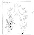
Images


Landscapes
- Apparatus For Radiation Diagnosis (AREA)
- Endoscopes (AREA)
Abstract
Translated fromChinese
Description
Translated fromChinese技术领域technical field
本发明涉及支持内窥镜的插入的插入支持系统。The present invention relates to an insertion support system for supporting insertion of an endoscope.
背景技术Background technique
近年来广泛采用基于图像的诊断,例如,通过利用X线CT(ComputedTomography)装置等拍摄被检体的断层像,在被检体内获得三维图像数据,使用该三维图像数据进行目标部位的诊断。In recent years, image-based diagnosis has been widely used. For example, by taking a tomographic image of a subject with an X-ray CT (Computed Tomography) device or the like, three-dimensional image data is obtained in the subject, and the target site is diagnosed using the three-dimensional image data.
在CT装置中,通过一边连续旋转着进行X线照射/检测,一边向体轴方向连续输送被检体,可以在被检体的三维区域中进行螺旋状的连续扫描(螺旋扫描:helical scan),根据三维区域的连续的切片断层像生成三维图像。In the CT apparatus, by continuously rotating and performing X-ray irradiation/detection, while continuously transporting the subject in the direction of the body axis, it is possible to perform helical continuous scanning (helical scan) in the three-dimensional area of the subject. , generating a three-dimensional image from consecutive slice tomograms of the three-dimensional region.
这种三维图像的一种图像中有肺的支气管的三维图像。支气管的三维图像用来三维掌握例如被怀疑为肺癌等的异常部的位置。并且,为了通过活检来确认异常部,插入支气管内窥镜并从前端部伸出活检针和活检钳子等,采取组织的样本(sample)。One such three-dimensional image is a three-dimensional image of the bronchi of the lungs. The three-dimensional image of the bronchi is used to three-dimensionally grasp the position of an abnormal part suspected of being lung cancer, for example. Then, in order to confirm an abnormal part by biopsy, a bronchoscope is inserted, a biopsy needle, biopsy forceps, etc. are extended from the distal end, and a tissue sample is taken.
在像支气管那样具有多个阶段的分支的管路中,在异常部的所在位置接近分支的末梢时,使内窥镜的前端在短时间内准确到达目标部位比较困难,因此例如在日本国特开2000-135215号公报等中提出了一种装置,根据被检体的三维区域的图像数据生成所述被检体内的管路的三维像,在所述三维像上求出沿着所述管路到达目标地点的路径,根据所述图像数据生成沿着所述路径的所述管路的虚拟内视像,并显示所述虚拟内视像,从而把支气管内窥镜导航到目标部位。In a pipeline with multi-stage branches like the bronchi, when the position of the abnormal part is close to the end of the branch, it is difficult to make the front end of the endoscope reach the target site accurately in a short time. KOKAI Publication No. 2000-135215 and the like propose a device that generates a three-dimensional image of a pipeline in the subject based on image data of a three-dimensional region of the subject, and calculates the distance along the tube from the three-dimensional image. A route to a target site, generating a virtual endoscopic image of the pipeline along the route according to the image data, and displaying the virtual endoscopic image, thereby navigating the bronchoscope to the target site.
但是,作为目标部位的活体组织一般具有一定的范围,所以利用点指定活检时的活检位置并不合适,期望指定为一定大小的目标区域,但在以往的装置中不能把导航的终点指定为这种目标区域,存在不能确定从始点到目标区域的导航路径的问题。However, the living tissue as the target site generally has a certain range, so it is not appropriate to specify the biopsy position when using points. It is desired to specify a target area of a certain size. This kind of target area has the problem that the navigation path from the starting point to the target area cannot be determined.
发明内容Contents of the invention
本发明就是鉴于上述情况而提出的,其目的在于提供一种插入支持系统,能够在任意区域指定关心部位,并且能够恰当地设定到达所指定区域的导航。The present invention has been made in view of the above circumstances, and an object of the present invention is to provide an insertion support system capable of specifying a site of interest in an arbitrary area and appropriately setting navigation to the specified area.
本发明的插入支持系统构成为具有:虚拟图像生成单元,其根据被检体的三维区域的图像数据,生成所述被检体内的体腔管路上的虚拟图像;路径始点设定单元,其在所述虚拟图像上设定内窥镜通往所述被检体内的体腔管路上的插入路径的始点;关心区域设定单元,其在所述虚拟图像上设定所述被检体内的关心部位的区域;路径终点抽取单元,其在所述虚拟图像上根据所述关心部位的区域,抽取所述内窥镜通往所述被检体内的体腔管路上的插入路径的终点。The insertion support system of the present invention is configured to include: a virtual image generating unit that generates a virtual image on a body cavity line in the subject based on image data of a three-dimensional region of the subject; and a path starting point setting unit that setting the starting point of the insertion path of the endoscope leading to the body cavity in the subject on the virtual image; an area of interest setting unit, which sets the position of the site of interest in the subject on the virtual image region: a path end extraction unit, which extracts the end point of the insertion path of the endoscope leading to the body cavity in the subject according to the region of the site of interest on the virtual image.
本发明的插入支持系统具有可以在任意区域指定关心部位,而且能够恰当地设定到达所指定区域的导航的效果。The insertion support system of the present invention has the effect that a site of interest can be specified in an arbitrary area, and navigation to the specified area can be appropriately set.
附图说明Description of drawings
图1是表示本发明的实施例1的支气管插入支持系统的结构的结构图。FIG. 1 is a structural diagram showing the structure of a bronchial insertion support system according to
图2是表示图1的插入支持装置生成导航数据的处理流程的流程图。FIG. 2 is a flowchart showing the flow of processing for generating navigation data by the insertion support device in FIG. 1 .
图3是表示在图2的处理中展开的路径设定画面的第1图。FIG. 3 is a first diagram showing a route setting screen developed in the process of FIG. 2 .
图4是表示在图2的处理中展开的路径设定画面的第2图。FIG. 4 is a second diagram showing a route setting screen developed in the process of FIG. 2 .
图5是表示在图2的处理中展开的路径设定画面的第3图。FIG. 5 is a third diagram showing a route setting screen developed in the process of FIG. 2 .
图6是表示在图2的处理中展开的路径设定画面的第4图。FIG. 6 is a fourth diagram showing a route setting screen developed in the process of FIG. 2 .
图7是表示在图2的处理中展开的路径设定画面的第5图。FIG. 7 is a fifth diagram showing a route setting screen developed in the process of FIG. 2 .
图8是表示图2的路径设定处理的流程的流程图。FIG. 8 is a flowchart showing the flow of route setting processing in FIG. 2 .
图9是说明图8的处理的第1图。FIG. 9 is a first diagram illustrating the processing of FIG. 8 .
图10是说明图8的处理的第2图。FIG. 10 is a second diagram illustrating the processing of FIG. 8 .
图11是表示在图8的处理中展开的路径设定画面的第1图。FIG. 11 is a first diagram showing a route setting screen developed in the process of FIG. 8 .
图12是说明图8的处理的第3图。FIG. 12 is a third diagram illustrating the processing of FIG. 8 .
图13是表示在图8的处理中展开的路径设定画面的第2图。Fig. 13 is a second diagram showing a route setting screen developed in the process of Fig. 8 .
图14是说明图8的处理的第4图。FIG. 14 is a fourth diagram illustrating the processing of FIG. 8 .
图15是表示在图8的处理中展开的路径设定画面的第3图。FIG. 15 is a third diagram showing a route setting screen developed in the process of FIG. 8 .
图16是表示在图2的处理中展开的插入支持画面的图。Fig. 16 is a diagram showing an insertion support screen developed in the process of Fig. 2 .
图17是表示在图8的处理中展开的路径设定画面的第1变形例的图。FIG. 17 is a diagram showing a first modified example of the route setting screen developed in the process of FIG. 8 .
图18是表示在图8的处理中展开的路径设定画面的第2变形例的图。FIG. 18 is a diagram showing a second modified example of the route setting screen developed in the process of FIG. 8 .
图19是表示本发明的实施例2的支气管插入支持系统的结构的结构图。Fig. 19 is a structural diagram showing the structure of a bronchial insertion support system according to
图20是表示图19所示的插入支持装置生成插入支持数据的处理流程的流程图。FIG. 20 is a flowchart showing the flow of processing for generating insertion support data by the insertion support device shown in FIG. 19 .
图21是表示在图20的处理中展开的患者信息选择画面的图。FIG. 21 is a diagram showing a patient information selection screen developed in the process of FIG. 20 .
图22是表示在图20的处理中展开的路径设定画面的图。FIG. 22 is a diagram showing a route setting screen developed in the process of FIG. 20 .
图23是说明图22的支气管断层图像和MPR图像的显示方法的特征的第1图。FIG. 23 is a first diagram illustrating the features of the method of displaying the bronchial tomographic image and the MPR image in FIG. 22 .
图24是说明图22的支气管断层图像和MPR图像的显示方法的特征的第2图。FIG. 24 is a second diagram illustrating the features of the method of displaying the bronchial tomographic image and the MPR image in FIG. 22 .
图25是说明图22的支气管断层图像和MPR图像的显示方法的特征的第3图。FIG. 25 is a third diagram illustrating the features of the method of displaying the bronchial tomographic image and the MPR image in FIG. 22 .
图26是说明图22的支气管断层图像和MPR图像的显示方法的特征的第4图。FIG. 26 is a fourth diagram illustrating the features of the method of displaying the bronchial tomographic image and the MPR image in FIG. 22 .
图27是表示图20的路径设定处理的流程的第1流程图。FIG. 27 is a first flowchart showing the flow of route setting processing in FIG. 20 .
图28是表示图20的路径设定处理的流程的第2流程图。FIG. 28 is a second flowchart showing the flow of route setting processing in FIG. 20 .
图29是说明图27和图28所示的处理的第1图。Fig. 29 is a first diagram for explaining the processing shown in Figs. 27 and 28 .
图30是说明图27和图28所示的处理的第2图。Fig. 30 is a second diagram illustrating the processing shown in Figs. 27 and 28 .
图31是说明图27和图28所示的处理的第3图。Fig. 31 is a third diagram illustrating the processing shown in Figs. 27 and 28 .
图32是说明图27和图28所示的处理的第4图。Fig. 32 is a fourth diagram illustrating the processing shown in Figs. 27 and 28 .
图33是说明图27和图28所示的处理的第5图。Fig. 33 is a fifth diagram illustrating the processing shown in Figs. 27 and 28 .
图34是说明图27和图28所示的处理的第6图。Fig. 34 is a sixth diagram illustrating the processing shown in Figs. 27 and 28 .
图35是说明图27和图28所示的处理的第7图。Fig. 35 is a seventh diagram illustrating the processing shown in Figs. 27 and 28 .
图36是说明图27和图28所示的处理的第8图。Fig. 36 is an eighth diagram illustrating the processing shown in Figs. 27 and 28 .
图37是说明图27和图28所示的处理的第9图。Fig. 37 is a ninth diagram illustrating the processing shown in Figs. 27 and 28 .
图38是表示利用图19的插入支持装置生成的插入支持画面的图。Fig. 38 is a diagram showing an insertion support screen created by the insertion support device of Fig. 19 .
图39是表示本发明的实施例3的支气管插入支持系统的结构的结构图。Fig. 39 is a structural diagram showing the structure of a bronchial insertion support system according to
图40是表示图39的插入支持装置生成插入支持数据的处理流程的流程图。FIG. 40 is a flowchart showing the flow of processing for generating insertion support data by the insertion support device of FIG. 39 .
图41是表示在图40的处理中展开的患者信息选择画面的图。FIG. 41 is a diagram showing a patient information selection screen developed in the process of FIG. 40 .
图42是表示在图40的处理中展开的路径设定画面的图。Fig. 42 is a diagram showing a route setting screen developed in the process of Fig. 40 .
图43是说明图42的支气管图像和MPR图像的显示方法的特征的第1图。FIG. 43 is a first diagram illustrating the features of the method of displaying the bronchial image and the MPR image in FIG. 42 .
图44是说明图42的支气管图像和MPR图像的显示方法的特征的第2图。FIG. 44 is a second diagram illustrating the features of the method of displaying the bronchial image and the MPR image in FIG. 42 .
图45是说明图42的支气管图像和MPR图像的显示方法的特征的第3图。FIG. 45 is a third diagram illustrating the features of the method of displaying the bronchus image and the MPR image in FIG. 42 .
图46是说明图42的支气管图像和MPR图像的显示方法的特征的第4图。FIG. 46 is a fourth diagram illustrating the features of the method of displaying the bronchus image and the MPR image in FIG. 42 .
图47是表示图40的路径设定处理的流程的第1流程图。FIG. 47 is a first flowchart showing the flow of route setting processing in FIG. 40 .
图48是表示图40的路径设定处理的流程的第2流程图。FIG. 48 is a second flowchart showing the flow of route setting processing in FIG. 40 .
图49是说明图47和图48的处理的第1图。Fig. 49 is a first diagram for explaining the processing of Figs. 47 and 48 .
图50是说明图47和图48的处理的第2图。Fig. 50 is a second diagram for explaining the processing of Figs. 47 and 48 .
图51是说明图47和图48的处理的第3图。Fig. 51 is a third diagram illustrating the processing of Figs. 47 and 48 .
图52是说明图47和图48的处理的第4图。Fig. 52 is a fourth diagram illustrating the processing of Figs. 47 and 48 .
图53是说明图47和图48的处理的第5图。Fig. 53 is a fifth diagram illustrating the processing of Figs. 47 and 48 .
图54是说明图47和图48的处理的第6图。Fig. 54 is a sixth diagram illustrating the processing of Figs. 47 and 48 .
图55是说明图47和图48的处理的第7图。Fig. 55 is a seventh diagram illustrating the processing of Figs. 47 and 48 .
图56是说明图47和图48的处理的第8图。FIG. 56 is an eighth diagram illustrating the processing of FIGS. 47 and 48 .
图57是说明图47和图48的处理的第9图。Fig. 57 is a ninth diagram illustrating the processing of Figs. 47 and 48 .
图58是表示利用图39的插入支持装置生成的插入支持画面的图。Fig. 58 is a diagram showing an insertion support screen created by the insertion support device of Fig. 39 .
具体实施方式Detailed ways
以下,参照附图说明本发明的实施例。Hereinafter, embodiments of the present invention will be described with reference to the drawings.
(实施例1)(Example 1)
如图1所示,本实施例1的支气管插入支持系统1由支气管内窥镜装置3和插入支持装置5构成。As shown in FIG. 1 , a bronchial
插入支持装置5根据CT图像数据生成支气管内部的虚拟的内视像(以下表述为VBS图像),并且将通过支气管内窥镜装置3得到的内窥镜图像(以下表述为实时图像)与VBS图像合成,并显示在监视器6上,由此进行支气管内窥镜装置3向支气管的插入支持。The
并且,支气管内窥镜装置3虽然未图示,但是由具有摄像单元的支气管镜、为支气管镜提供照明光的光源、和对来自支气管镜的摄像信号进行信号处理的摄像机控制单元等构成,把支气管镜插入患者体内的支气管中,拍摄支气管内部,对支气管末端的目标组织进行活检,并且将实时图像和VBS图像合成显示在监视器7上。In addition, although not shown in the figure, the
监视器7设有由触摸屏构成的输入部8,能够一面进行插入处理一面容易地操作由触摸屏构成的输入部8。The
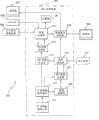
插入支持装置5由以下部分构成:CT图像数据取入部11,其通过例如MO(Magnetic Optical disk:磁光盘)装置或DVD(Digital VersatileDisk:数字通用磁盘)装置等可移动的存储介质,取入由拍摄患者的X线断层像的未图示的公知CT装置生成的三维图像数据;CT图像数据存储部12,其存储通过CT图像数据取入部11取入的CT图像数据;MPR图像生成部13,其根据存储在CT图像数据存储部12中的CT图像数据,生成MPR图像(多断面再构建图像);路径设定部14,其生成具有MPR图像生成部13所生成的MPR图像的后述的路径设定画面,设定支气管内窥镜装置3的通往支气管的支持路径(以下仅表述为路径);作为虚拟图像生成单元的VBS图像生成部15,其根据存储在CT图像数据存储部12中的CT图像数据,以帧为单位生成由路径设定部14设定的路径连续的VBS图像;VBS图像存储部16,其存储VBS图像生成部15生成的VBS图像;作为导航图像生成单元的图像处理部17,其输入来自支气管内窥镜装置3的摄像信号和来自输入部8的输入信号,利用存储器20生成由实时图像、VBS图像和多个缩略VBS图像构成的后述的插入支持画面;图像显示控制部18,其使监视器6显示路径设定部14生成的路径设定画面和图像处理部17生成的插入支持画面;输入装置19,其由向路径设定部14输入设定信息的键盘和指针器件构成。
支气管内窥镜装置3从插入支持装置5的图像处理部17接收VBS图像和缩略VBS图像,与实时图像合成,在监视器7上显示与插入支持装置5显示于监视器6上的插入支持画面相同的画面,并且把来自监视器7的由触摸屏构成的输入部8的输入信息输出给插入支持装置5的图像处理部17。The
另外,CT图像数据存储部12和VBS图像存储部16可以由一个硬盘构成,另外,MPR图像生成部13、路径设定部14、VBS图像生成部15和图像处理部17可以由一个运算处理电路构成。并且,CT图像数据取入部11通过MO或DVD等可移动的存储介质取入CT图像数据,但在CT装置或保存CT图像数据的医院内服务器连接医院内LAN时,也可以由可连接该医院内LAN的接口电路构成CT图像数据取入部11,通过医院内LAN取入CT图像数据。In addition, the CT image
对这样构成的本实施方式的作用进行说明。The operation of this embodiment configured in this way will be described.
如图2所示,在利用支气管内窥镜装置3进行观察/处置之前,插入支持装置5在步骤S1中,通过CT图像数据取入部11取入由CT装置生成的患者的CT图像数据,在步骤S2中把所取入的CT图像数据存储在CT图像数据存储部12中。As shown in FIG. 2 , before the observation/treatment is performed with the
在步骤S3中,通过路径设定部14使监视器6显示图3所示的路径设定画面21,在路径设定画面21上的患者信息标签画面22中选择患者信息。根据该选择,在步骤S4中,生成所选择的患者的例如由3个不同的多断面像构成的MPR图像,在步骤S5中,在路径设定画面21上显示该MPR图像23a、23b、23c。在路径设定画面21中设有显示VBS图像的VBS图像显示区域23d。In step S3 , the
另外,患者信息标签画面22中的患者信息的选择,通过利用输入装置19输入识别患者的患者ID来进行。In addition, selection of patient information on the patient
然后,在步骤S6中,当利用输入装置19选择路径设定画面21上的路径设定标签24(参照图3)时,图4所示的路径设定标签画面25显示在路径设定画面21上,进行后述的路径设定处理,设定支气管镜在支气管内的插入支持路径。Then, in step S6, when using the
在设定了插入支持路径时,在步骤S7中,通过VBS图像生成部15以帧为单位生成所设定的所有路径连续的VBS图像,在步骤S8中,把所生成的VBS图像存储在VBS图像存储部16中。When the insertion support path is set, in step S7, the VBS
通过上述的步骤S1~S8的处理,完成使用支气管镜观察/处置时的插入支持装置5的插入支持的准备。Through the above-described processing of steps S1 to S8 , preparations for insertion support by the
此处,使用图5~图8说明上述步骤S6的路径设定处理。Here, the route setting process in step S6 described above will be described with reference to FIGS. 5 to 8 .
当在路径设定画面21中选择了路径搜索按钮时,开始步骤S6的路径设定处理。具体来讲,图5所示的催促输入路径的始点的始点输入指示窗口31显示在路径设定画面21上,在路径设定画面21上使用光标30在MPR图像23a、23b、23c中的一个断层像上设定始点71。设定始点71后,在MPR图像23a、23b、23c的其他两个断层像上的对应位置处也设定始点71,并且在VBS图像显示区域23d上显示始点71的VBS图像,图6所示的催促设定路径的终点即活检区域72的活检区域输入指示窗口32显示在路径设定画面21上。When the route search button is selected on the
在该图6的路径设定画面21上,使用光标30在MPR图像23中的一个断层像上二维描画活检区域72来进行设定。此时设定的活检区域72的数量不限于一个,也可以指定多个,在图6中示出了指定两个活检区域72a、72b的状态。On the
并且,在活检区域72的设定结束后,图7所示的设定每一个活检区域72的搜索路径数量的路径数量设定窗口33显示在路径设定画面21上。通过设定每一个活检区域72的搜索路径数量,可以搜索出多条导航对象在活检区域72中的靠近路径(approach route)。Then, after the setting of the
根据图5~图7,在设定了始点、活检区域72和搜索路径数量后,按照图8所示的处理搜索路径。According to FIGS. 5 to 7 , after setting the starting point, the
即,如图8所示,在步骤S11中,检测出所设定的活检区域72的数量,在步骤S12中,读入搜索路径数量n,在步骤S13中,读入始点71的位置。That is, as shown in FIG. 8, in step S11, the number of
并且,在步骤S14中,抽取活检区域72的重心位置,在步骤S15中,把r设为Δr后,在步骤S16中,把以重心位置为中心的半径为r的圆内部指定为搜索区域。In addition, in step S14, the center of gravity of the
在步骤S17中,判断搜索区域内是否有支气管,在有支气管时,在步骤S18中,确定把该位置作为终点的路径候选。In step S17, it is judged whether there is a bronchus in the search area, and if there is a bronchus, in step S18, a route candidate with this position as the end point is specified.
在确定了路径候选后,在步骤S19中,判断所确定的路径候选是否已登记,在没有登记的情况下,在步骤S20中,生成基于从始点到终点的分支点名称的路径名称,并作为支持路径登记。After the route candidate is determined, in step S19, it is judged whether the determined route candidate is registered, and in the case of not registered, in step S20, the route name based on the branch point name from the start point to the end point is generated, and used as Support path registration.
并且,在步骤S21中,判断所登记的路径数量是否小于在步骤S12中读入的路径数量n。And, in step S21, it is judged whether the number of registered routes is smaller than the number n of routes read in in step S12.
另外,在步骤S17中判断为搜索区域内没有支气管时,在步骤S19中所确定的路径候选已登记时,或者在步骤S21中已登记的路径数量小于路径数量n时,在步骤S22中,把r设为r+Δr来放大搜索区域,并返回步骤S16。In addition, when it is determined in step S17 that there is no bronchus in the search area, when the route candidates determined in step S19 have been registered, or when the number of registered routes in step S21 is less than the number n of routes, in step S22, the Set r to r+Δr to enlarge the search area, and return to step S16.
在已登记的路径数量达到在步骤S12中读入的路径数量n时,在步骤S23中,判断是否已搜索所设定的所有活检区域72,如果已搜索所有活检区域72则结束处理,在还有未搜索的活检区域72时,在步骤S24中抽取下一个活检区域72的重心位置,并返回步骤S15。When the registered path quantity reaches the path quantity n read in in step S12, in step S23, it is judged whether all
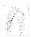
具体来讲,如图9所示,在支气管101的端部被指定了活检区域72时,抽取活检区域72的重心103。Specifically, as shown in FIG. 9 , when the
并且,如图10所示,把以该重心103为中心的圆设为搜索区域104,放大搜索区域104直到支气管101位于搜索区域104内,把支气管101最先位于搜索区域104内的点设为终点105,如图11所示,确定连接始点71和该终点105的第1路径候选106,如果该第1路径候选106尚未登记,则作为第1支持路径进行登记。此时的路径名称根据将要通过的分支点名称来命名。And, as shown in FIG. 10 , set the circle centered on the center of
在确定了第1支持路径后,如图12所示,增大以重心103为中心的搜索区域104的半径,放大搜索区域104,把之后支气管位于搜索区域104内的点设为终点107,如图13所示,确定连接始点71和该终点107的第2路径候选108,如果该第2路径候选108尚未登记,则作为第2支持路径进行登记。在图13中,第2路径候选108与图11中的第1支持路径不同,所以第2路径候选108成为第2支持路径。此时的路径名称也根据将要通过的分支点名称来命名。After the first support path is determined, as shown in Figure 12, increase the radius of the
在本实施例中,由于路径数量为3个,所以在确定了第2支持路径后,完全相同地,如图14所示,进一步增大以重心103为中心的搜索区域104的半径,放大搜索区域104,把之后支气管位于搜索区域104内的点设为终点109,如图15所示,确定连接始点71和该终点109的第3路径候选110,如果该第3路径候选110尚未登记,则作为第3支持路径进行登记。在图15中,由于第3路径候选110与第1和第2支持路径不同,所以第3路径候选110成为第3支持路径。此时的路径名称也根据将要通过的分支点名称来命名。In this embodiment, since the number of paths is 3, after the second support path is determined, as shown in FIG. In the
这样,可以设定所指定的路径数量的支持路径。对所有活检区域72执行这些处理,对每个活检区域72设定所指定的路径数量的支持路径。In this way, the specified number of supported paths can be set. These processes are executed for all
当在插入支持装置5的插入支持下,开始在这样设定的支持路径中的支气管内窥镜检查时,在监视器7上显示如图16所示的插入支持画面51。另外,也在监视器6上显示和监视器7相同的插入支持画面51。When the bronchoendoscopy in the support route thus set is started with the insertion support of the
该插入支持画面51包括:显示来自支气管内窥镜装置3的实时图像的内窥镜实时图像显示区域52;显示VBS图像53a的VBS图像显示区域53;将路径的所有分支点的VBS图像53a缩小显示为分支缩略VBS图像54(a)~54(j)的分支缩略VBS图像区域54,与实时图像所在的分支点对应的虚拟图像即VBS图像53a显示在VBS图像显示区域53上。The
此处,与显示在VBS图像显示区域53上的VBS图像53a相同的分支缩略VBS图像的框显示为粗框或彩色,可以与其他的分支缩略VBS图像区分,手术医生能够容易识别显示在VBS图像显示区域53上的VBS图像是哪个分支的图像。Here, the frame of the same branch thumbnail VBS image as the
另外,也可以按照图17所示那样,将所有的支持路径以区分颜色的方式同时显示在MPR图像23a、23b、23c上。并且,在MPR图像23a、23b、23c上指定始点和活检区域,但不限于此,也可以如图18所示,在路径设定画面21上显示支气管的三维图像151,在三维图像151中指定始点71和活检区域72,以进行路径搜索。In addition, as shown in FIG. 17 , all support paths may be simultaneously displayed on the
(实施例2)(Example 2)
如图19所示,本实施例2的支气管插入支持系统301由支气管内窥镜装置303和插入支持装置305构成。As shown in FIG. 19 , a bronchial insertion support system 301 according to the second embodiment includes a bronchial endoscope device 303 and an insertion support device 305 .
插入支持装置305根据CT图像数据生成支气管内部的虚拟的内视像(以下表述为VBS图像),并且将通过支气管内窥镜装置303得到的内窥镜图像(以下表述为实时图像)与VBS图像合成,并显示在监视器306上,由此进行支气管内窥镜装置303向支气管的插入支持。The insertion support device 305 generates a virtual internal video image (hereinafter referred to as a VBS image) of the inside of the bronchus based on the CT image data, and combines the endoscopic image (hereinafter referred to as a real-time image) obtained by the bronchial endoscope device 303 with the VBS image. The results are synthesized and displayed on the
并且,支气管内窥镜装置303虽然未图示,但是由具有摄像单元的支气管镜、为支气管镜提供照明光的光源、和对来自支气管镜的摄像信号进行信号处理的摄像机控制单元等构成,把支气管镜插入患者体内的支气管中,拍摄支气管内部,对支气管末端的目标组织进行活检,并且将实时图像和VBS图像合成显示在监视器307上。In addition, although not shown, the bronchoendoscopic device 303 is composed of a bronchoscope having an imaging unit, a light source for supplying illumination light to the bronchoscope, and a camera control unit for performing signal processing on imaging signals from the bronchoscope, and the like. A bronchoscope is inserted into the bronchi of the patient, photographs the inside of the bronchi, biopsies the target tissue at the end of the bronchus, and displays the real-time image and the VBS image on the monitor 307 .
监视器307设有由触摸屏构成的输入部308,能够一面进行插入处理一面容易地操作由触摸屏构成的输入部308。The monitor 307 is provided with an input unit 308 made of a touch panel, and the input unit 308 made of a touch panel can be easily operated while performing insertion processing.
插入支持装置305由以下部分构成:CT图像数据取入部311,其通过例如MO(Magnetic Optical disk)装置或DVD(Digital Versatile Disk)装置等可移动的存储介质,取入由拍摄患者的X线断层像的未图示的公知CT装置生成的三维图像数据;CT图像数据存储部312,其存储通过CT图像数据取入部311取入的CT图像数据;脏器抽取部320,其抽取存储在CT图像数据存储部312中的作为CT图像数据的规定脏器即支气管的三维信息的区段(segmentation);MPR图像生成部313,其根据存储在CT图像数据存储部312中的CT图像数据,生成MPR图像(多断面再构建图像),并且在MPR图像上重叠显示脏器抽取部320抽取的支气管的支气管断层图像;路径设定部314,其生成具有MPR图像生成部313生成的MPR图像的后述的路径设定画面,设定支气管内窥镜装置303通往支气管的支持路径(以下仅表述为路径);VBS图像生成部315,其根据存储在CT图像数据存储部312中的CT图像数据,以帧为单位生成由路径设定部314设定的路径连续的VBS图像;VBS图像存储部316,其存储VBS图像生成部315生成的VBS图像;图像处理部317,其输入来自支气管内窥镜装置303的摄像信号和来自输入部308的输入信号,生成由实时图像、VBS图像和多个缩略VBS图像构成的后述的插入支持画面;图像显示控制部318,其使监视器306显示路径设定部314生成的路径设定画面和图像处理部317生成的插入支持画面;输入装置319,其由向路径设定部314输入设定信息的键盘和指针器件构成。The insertion support device 305 is composed of the following parts: CT image data acquisition unit 311, which imports the X-ray tomography of the patient through a removable storage medium such as a MO (Magnetic Optical disk) device or a DVD (Digital Versatile Disk) device. The three-dimensional image data generated by a known CT device not shown in the figure; the CT image data storage unit 312, which stores the CT image data acquired by the CT image data acquisition unit 311; the organ extraction unit 320, which extracts the CT image data stored in the CT image The segment (segmentation) of the three-dimensional information of the bronchi, which is a predetermined organ as CT image data in the data storage unit 312; the MPR image generation unit 313, which generates the MPR based on the CT image data stored in the CT image data storage unit 312. image (multi-sectional reconstructed image), and the bronchial tomographic image of the bronchi extracted by the organ extraction unit 320 is superimposed on the MPR image; The path setting screen of the bronchoscope device 303 sets the support path leading to the bronchi (hereinafter only expressed as path); the VBS image generation part 315, based on the CT image data stored in the CT image data storage part 312, The VBS image of the route set by the route setting part 314 is generated in units of frames; the VBS image storage part 316 stores the VBS image generated by the VBS image generating part 315; the image processing part 317 receives input from the bronchoscope The imaging signal of the device 303 and the input signal from the input unit 308 generate a later-described insertion support screen composed of a live image, a VBS image, and a plurality of thumbnail VBS images; an image display control unit 318 causes the
支气管内窥镜装置303从插入支持装置305的图像处理部317接收VBS图像和缩略VBS图像,并与实时图像合成显示在监视器307上,并且把来自监视器307的由触摸屏构成的输入部308的输入信息输出给插入支持装置305的图像处理部317。The bronchoscope device 303 receives the VBS image and the thumbnail VBS image from the image processing unit 317 of the insertion support device 305, and synthesizes and displays the real-time image on the monitor 307, and transmits the input unit composed of a touch screen from the monitor 307 The input information at 308 is output to the image processing unit 317 of the insertion support device 305 .
另外,CT图像数据存储部312和VBS图像存储部316可以由一个硬盘构成,另外,MPR图像生成部313、路径设定部314、VBS图像生成部315和图像处理部317可以由一个运算处理电路构成。并且,CT图像数据取入部311通过MO或DVD等可移动的存储介质取入CT图像数据,但在CT装置或保存CT图像数据的医院内服务器连接医院内LAN时,也可以由可连接该医院内LAN的接口电路构成CT图像数据取入部311,通过医院内LAN取入CT图像数据。In addition, the CT image data storage unit 312 and the VBS image storage unit 316 can be composed of one hard disk, and the MPR image generation unit 313, the route setting unit 314, the VBS image generation unit 315, and the image processing unit 317 can be composed of one arithmetic processing circuit. constitute. Furthermore, the CT image data acquisition unit 311 acquires CT image data through a removable storage medium such as MO or DVD. The interface circuit of the intra-LAN constitutes the CT image data acquisition unit 311, and acquires CT image data via the intra-hospital LAN.
对这样构成的本实施例的作用进行说明。The operation of the present embodiment thus constituted will be described.
如图20所示,在利用支气管内窥镜装置303进行观察/处置之前,插入支持装置305在步骤S301中,通过CT图像数据取入部311取入由CT装置生成的患者的CT图像数据,在步骤S302中把所取入的CT图像数据存储在CT图像数据存储部312中。As shown in FIG. 20 , before observation/treatment is performed with the bronchoscope apparatus 303, the insertion support apparatus 305, in step S301, imports the CT image data of the patient generated by the CT apparatus through the CT image data acquisition unit 311. In step S302 , the imported CT image data is stored in the CT image data storage unit 312 .
在步骤S303中,通过路径设定部314使监视器306显示图21所示的患者信息选择画面322,在患者信息选择画面322中选择患者信息。并且,利用基于输入装置319的操作的指针324选择患者信息选择画面322的路径设定按钮323,由此,在步骤S304中,在MPR图像生成部313中生成所选择的患者的例如由3个不同的多断面像构成的MPR图像325,在监视器306上显示图22所示的路径设定画面326,该路径设定画面326具有由轴向(axial)图像325a、冠状(coronal)图像325b、径向(sagittal)图像325c构成的MPR图像325、和显示路径信息的路径信息画面328。In step S303 , the route setting unit 314 causes the
另外,在路径设定部314中进行的患者信息选择画面322中的患者信息的选择,通过利用输入装置319输入识别患者的患者ID来进行。In addition, selection of patient information on the patient information selection screen 322 performed in the route setting unit 314 is performed by inputting a patient ID for identifying the patient using the input device 319 .
然后,在步骤S305中,利用脏器抽取部320抽取存储在CT图像数据存储部312中的CT图像数据的规定脏器即支气管,生成所抽取的支气管的支气管断层图像327,并输出给MPR图像生成部313,按照图22所示,在MPR图像325上重叠显示所抽取的支气管的支气管断层图像327。Then, in step S305, the bronchi, which is a predetermined organ of the CT image data stored in the CT image data storage unit 312, is extracted by the organ extraction unit 320, and a bronchial
另外,MPR图像325的轴向图像325a、冠状图像325b、径向图像325c的各个图像例如由黑白图像构成,将要重叠的支气管断层图像327利用蓝色图像(在图22中为斜线阴影部分的图像)显示,可以在视觉上区分显示MPR图像325的轴向图像325a、冠状图像325b、径向图像325c的各个图像和支气管断层图像327。In addition, each of the
然后,在步骤S306中,在路径设定画面321上进行后述的路径设定处理,设定在支气管中的支气管镜的插入支持路径。Then, in step S306 , a path setting process described later is performed on the path setting screen 321 to set an insertion support path for the bronchoscope in the bronchi.
在设定了插入支持路径时,在步骤S307中,通过VBS图像生成部315以帧为单位生成所设定的所有路径连续的VBS图像,在步骤S308中,把所生成的VBS图像存储在VBS图像存储部316中。When the insertion support path is set, in step S307, the VBS image generation unit 315 generates VBS images of all the set paths continuous in frame units, and in step S308, the generated VBS images are stored in the VBS In the image storage unit 316.
通过上述的步骤S301~S308的处理,完成使用支气管镜观察/处置时的插入支持装置305的插入支持的准备。Through the processing of steps S301 to S308 described above, preparations for insertion support by the insertion support device 305 at the time of bronchoscopic observation/treatment are completed.
此处,使用图22~图26说明图22所示的重叠的支气管断层图像327和MPR图像325的显示方法的特征。Here, the characteristics of the method of displaying the superimposed bronchial
在图22的路径设定画面326中,使用输入装置319,通过指针324操作路径信息区域328上的透明度设定框330,可以设定MPR图像325和将要重叠的管腔脏器抽取结果图像即支气管断层图像327在监视器306上的各自透明度,图22表示把MPR图像325和支气管断层图像327的透明度都设为0%时的显示示例。In the
具体来讲,在透明度设定框330中设有MPR图像透明度增减按钮330a和管腔脏器抽取结果图像透明度增减按钮330b,使用输入装置319,通过指针324操作MPR图像透明度增减按钮330a和管腔脏器抽取结果图像透明度增减按钮330b,从而可以增减MPR图像325和支气管断层图像327的透明度。Specifically, the MPR image transparency increase/
图23是把MPR图像325的透明度设为0%、把支气管断层图像327的透明度设为50%时的显示示例,图24是把MPR图像325的透明度设为0%、把支气管断层图像327的透明度设为100%时的显示示例。如图22~图24所示,通过使支气管断层图像327的透明度可变,可以在MPR图像325上进行支气管断层图像327的强调显示(图22、图23),以及进行把支气管断层图像327融合到MPR图像325中的融合显示(图24)。23 is a display example when the transparency of the
图25是把MPR图像325的透明度设为50%、把支气管断层图像327的透明度设为0%时的显示示例,图26是把MPR图像325的透明度设为100%、把支气管断层图像327的透明度设为0%时的显示示例。如图22、图25和图26所示,通过使MPR图像325的透明度可变,可以进行MPR图像325上的支气管断层图像327的强调显示(图22、图25),以及进行只显示支气管断层图像327的支气管单独显示(图26)。25 is a display example when the transparency of the
这样,通过操作MPR图像透明度增减按钮330a和管腔脏器抽取结果图像透明度增减按钮330b,可以任意增减MPR图像325和支气管断层图像327的透明度,通过以所期望的强调程度在MPR图像325上重叠显示基于CT图像数据的支气管的管腔脏器抽取结果即支气管断层图像327,可以使手术医生在正常地观察MPR图像325的过程中确认MPR图像325上的支气管的位置。In this way, by operating the MPR image transparency increase/
另外,不限于支气管,例如当然也可以应用于利用MPR图像325确认肠管、胆道等其他管腔脏器的位置的情况。In addition, it is not limited to the bronchi, and of course it can also be applied to the case of confirming the position of other luminal organs such as intestines and biliary tracts using the
下面,参照图27~图37说明路径设定部314的上述步骤S306的路径设定处理。Next, the route setting process of the above step S306 by the route setting unit 314 will be described with reference to FIGS. 27 to 37 .
如图27所示,在步骤S321中,在MPR图像上获取支气管插入支持的终点位置的标志。具体来讲,如图29所示,例如当利用指针324点击MPR图像325的轴向图像325a时,在所点击的位置处显示出标志400。此时,在冠状图像325b、径向图像325c的各个图像上的对应位置处也显示出标志400。As shown in FIG. 27 , in step S321 , the mark of the terminal position of bronchial insertion support is acquired on the MPR image. Specifically, as shown in FIG. 29 , for example, when the
在利用指针324选择路径信息区域328上的追加按钮411时,路径设定部314获取在轴向图像325a、冠状图像325b、径向图像325c上被指定的标志400的三维坐标。When the
标志400如图30所示,由表示指针324点击的点的标志点400a及区域线400b构成,该区域线400b表示包括标志点400a的规定区域,以便可以在MPR图像325上视认标志点400a。因此,手术医生通过在MPR图像325上视认区域线400b,能够容易确认标志400的位置。As shown in FIG. 30 , the
并且,在步骤S322中,判断标志400是否在支气管内,在支气管内时,在步骤S323中,将标志点登记到通过点列表中。不在支气管内时,在步骤S328中,显示图37所示的确认窗口440。手术医生在把标志点指定到支气管外面时,如果选择“是”,则标志点即被登记到通过点列表中。登记在通过点列表中的标志400的三维坐标在路径信息区域328上的登记信息区域412(参照图29和图32)中被赋予序号并显示。Then, in step S322, it is determined whether the
并且,也可以显示图31所示的通过点确认窗口405。该通过点确认窗口405是用于确认三维显示的支气管像406上的标志400的窗口,手术医生利用通过点确认窗口405判断标志400是否被标记在规定的支气管内的位置处。In addition, the passing
并且,反复把通过点的标志400登记到通过点列表中的处理直到成为所期望的位置。Then, the process of registering the
图32表示登记了5个通过点后,利用标志400新指定第6个通过点的状态,如图32的MPR图像325上示出的那样,已登记的5个通过点400a例如显示为绿色的点。另外,在通过点确认窗口405中,已登记的5个通过点400a例如显示为绿色的点,第6个通过点421例如显示为红色的点。FIG. 32 shows a state in which the 6th passing point is newly designated by the
另外,例如在图32的MPR图像325上利用标志400指定第6个通过点时,手术医生通过图34所示的通过点确认窗口405判断为当前通过点421被标记在不适合对上次利用支气管像406指定的通过点位置进行插入支持的支气管内位置处时,利用指针324选择图32的路径信息区域328上的删除按钮414,从而可以解除标志400的指定。另外,在选择全部删除按钮415时,包括当前通过点421在内的所有通过点被删除。In addition, for example, when using the
这样,如图35所示的通过点确认窗口405那样,在从终点407到开始插入支持的所期望的始点425的期间,把所期望的通过点登记在通过点列表中,之后手术医生判断是否需要通过点的插值。In this way, as shown in the passing
在选择了路径插值按钮416时,在图28的步骤S326中进行规定的插值处理(例如在通过点之间直线插值)。When the
另外,在该插值处理中,在支气管内的通过点之间以规定间隔插值多个虚拟点,由此进行插值,但虚拟点的插值间隔可以在路径信息区域328上的插值间隔框417(参照图32)中任意设定。In addition, in this interpolation process, interpolation is performed by interpolating a plurality of virtual points at predetermined intervals between passing points in the bronchus, but the interpolation interval of the virtual points can be set in the
并且,在步骤S327中,由包括虚拟点在内的通过点构成的路径430被登记在通过点列表中。And, in step S327, the
但是,在步骤S327中登记的通过点未必在支气管内。因此在实施了插值处理的情况下,在步骤S327的处理后,在步骤S329中,从通过点列表中删除不在支气管内的通过点,并结束处理,在图36所示的通过点确认窗口405中显示出路径430。However, the passing point registered in step S327 is not necessarily inside the bronchi. Therefore, when the interpolation process is performed, after the processing in step S327, in step S329, the passing point that is not in the bronchi is deleted from the passing point list, and the processing ends, and the passing
按照上面所述,当利用路径设定部314设定路径430时,转入图20中的步骤S307的处理。如上所述,在步骤S307中,利用VBS图像生成部315以帧为单位生成所设定的路径430连续的VBS图像,在步骤S308中把所生成的VBS图像存储在VBS图像存储部316中。As described above, when the
关于使用这样进行路径设定的插入支持装置305和支气管内窥镜装置303进行观察/处置时的插入支持用的插入支持画面,为了简化说明,以路径的分支点为10个的情况为例进行说明。Regarding the insertion support screen for insertion support when observation/treatment is performed using the insertion support device 305 and the bronchoendoscope device 303 that perform the route setting in this way, for the sake of simplicity of description, a case where there are 10 branch points of the route is taken as an example. illustrate.
当在插入支持装置305的插入支持下,开始支气管内窥镜检查时,在监视器306上显示图38所示那样的插入支持画面451。When the bronchoendoscopy is started with the insertion support of the insertion support device 305 , an
该插入支持画面451由以下部分构成:显示来自支气管内窥镜装置303的实时图像(未图示)的内窥镜实时图像显示区域452;显示VBS图像453a的VBS图像显示区域453;将路径的所有分支点的VBS图像453a缩小显示为分支缩略VBS图像454(a)~454(j)的分支缩略VBS图像区域454,在VBS图像显示区域453上显示路径的第一个分支点的VBS图像453a,在分支缩略VBS图像区域454上显示所有分支点的分支缩略VBS图像454(a)~454(j)。The
另外,在VBS图像453a上,在沿路径行进的路径孔处重叠显示导航标志455。并且,与显示在VBS图像显示区域453上的VBS图像453a相同的分支缩略VBS图像的框显示为粗框或彩色框,可以与其他的分支缩略VBS图像区分,手术医生能够容易地识别显示在VBS图像显示区域453上的VBS图像是哪个分支的图像。在第一个阶段中,分支缩略VBS图像454(a)的框显示为粗框或彩色框。In addition, on the
(实施例3)(Example 3)
如图39所示,本实施例3的支气管插入支持系统501由支气管内窥镜装置503和插入支持装置505构成。As shown in FIG. 39 , a bronchial
插入支持装置505根据CT图像数据生成支气管内部的虚拟的内视像(以下表述为VBS图像),并且将通过支气管内窥镜装置503得到的内窥镜图像(以下表述为实时图像)与VBS图像合成,并显示在监视器506上,由此进行支气管内窥镜装置503向支气管的插入支持。The
并且,支气管内窥镜装置503虽然未图示,但是由具有摄像单元的支气管镜、为支气管镜提供照明光的光源、和对来自支气管镜的摄像信号进行信号处理的摄像机控制单元等构成,把支气管镜插入患者体内的支气管中,拍摄支气管内部,对支气管末端的目标组织进行活检,并且将实时图像和VBS图像合成显示在监视器507上。In addition, although not shown in the figure, the
监视器507设有由触摸屏构成的输入部508,能够一面进行插入处理一面容易地操作由触摸屏构成的输入部508。The
插入支持装置505由以下部分构成:CT图像数据取入部511,其通过例如MO(Magnetic Optical disk)装置或DVD(Digital Versatile Disk)装置等可移动的存储介质,取入由拍摄患者的X线断层像的未图示的公知CT装置生成的三维图像数据;CT图像数据存储部512,其存储通过CT图像数据取入部511取入的CT图像数据;脏器抽取部520,其抽取存储在CT图像数据存储部512中的作为CT图像数据的规定脏器即支气管的三维信息的区段;MPR图像生成部513,其根据存储在CT图像数据存储部512中的CT图像数据,生成MPR图像(多断面再构建图像),并且在MPR图像上重叠显示脏器抽取部520抽取的支气管的支气管断层图像;路径设定部514,其生成具有MPR图像生成部513生成的MPR图像的后述的路径设定画面,设定支气管内窥镜装置503通往支气管的支持路径(以下仅表述为路径);VBS图像生成部515,其根据存储在CT图像数据存储部512中的CT图像数据,以帧为单位生成由路径设定部514设定的路径连续的VBS图像;VBS图像存储部516,其存储VBS图像生成部515生成的VBS图像;图像处理部517,其输入来自支气管内窥镜装置503的摄像信号和来自输入部508的输入信号,生成由实时图像、VBS图像和多个缩略VBS图像构成的后述的插入支持画面;图像显示控制部518,其使监视器506显示路径设定部514生成的路径设定画面、和图像处理部517生成的插入支持画面;输入装置519,其由向路径设定部514输入设定信息的键盘和指针器件构成。The
支气管内窥镜装置503从插入支持装置505的图像处理部517接收VBS图像和缩略VBS图像,并与实时图像合成显示在监视器507上,并且把来自监视器507的由触摸屏构成的输入部508的输入信息输出给插入支持装置505的图像处理部517。The
另外,CT图像数据存储部512和VBS图像存储部516可以由一个硬盘构成,另外,MPR图像生成部513、路径设定部514、VBS图像生成部515和图像处理部517可以由一个运算处理电路构成。并且,CT图像数据取入部511通过MO或DVD等可移动的存储介质取入CT图像数据,但在CT装置或保存CT图像数据的医院内服务器连接医院内LAN时,也可以由可连接该医院内LAN的接口电路构成CT图像数据取入部511,通过医院内LAN取入CT图像数据。In addition, the CT image
对这样构成的本实施例的作用进行说明。The operation of the present embodiment thus constituted will be described.
如图40所示,在利用支气管内窥镜装置503进行观察/处置之前,插入支持装置505在步骤S501中,通过CT图像数据取入部511取入由CT装置生成的患者的CT图像数据,在步骤S502中把所取入的CT图像数据存储在CT图像数据存储部512中。As shown in FIG. 40, before observation/treatment is performed by the
在步骤S503中,通过路径设定部514使监视器506显示图41所示的患者信息选择画面522,在患者信息选择画面522中选择患者信息。并且,利用基于输入装置519的操作的指针524选择患者信息选择画面522的路径设定按钮523,由此,在步骤S504中,在MPR图像生成部513中生成所选择患者的例如由3个不同的多断面像构成的MPR图像,在监视器506上显示图42所示的路径设定画面526,该路径设定画面526具有由轴向图像525a、冠状图像525b、径向图像525c构成的MPR图像525、和显示路径信息的路径信息画面528。In step S503 , the
另外,在路径设定部514中进行的患者信息选择画面522中的患者信息的选择,通过利用输入装置519输入识别患者的患者ID来进行。In addition, selection of patient information on the patient
然后,在步骤S505中,利用脏器抽取部520抽取存储在CT图像数据存储部512中的CT图像数据的规定脏器即支气管,生成所抽取的支气管的支气管断层图像527,并输出给MPR图像生成部513,按照图42所示,在MPR图像525上重叠显示所抽取的支气管的支气管断层图像527。Next, in step S505, the
另外,MPR图像525的轴向图像525a、冠状图像525b、径向图像525c的各个图像例如由黑白图像构成,将要重叠的支气管断层图像527利用蓝色图像(在图42中为斜线阴影部分的图像)显示,可以在视觉上区分显示MPR图像525的轴向图像525a、冠状图像525b、径向图像525c的各个图像和支气管断层图像527。In addition, each of the
然后,在步骤S506中,在路径设定画面521上进行后述的路径设定处理,设定在支气管中的支气管镜的插入支持路径。Then, in step S506 , a path setting process described later is performed on the path setting screen 521 to set an insertion support path for the bronchoscope in the bronchi.
在设定了插入支持路径时,在步骤S507中,通过VBS图像生成部515以帧为单位生成所设定的所有路径连续的VBS图像,在步骤S508中,把所生成的VBS图像存储在VBS图像存储部516中。When the insertion support path is set, in step S507, the VBS
通过上述的步骤S501~S508的处理,完成使用支气管镜观察/处置时的插入支持装置505的插入支持的准备。Through the above-described processing of steps S501 to S508 , preparations for insertion support by the
此处,使用图42~图46说明图42所示的重叠的支气管图像527和MPR图像525的显示方法的特征。Here, the characteristics of the method of displaying the superimposed
在图42所示的路径设定画面526中,使用输入装置519,通过指针524操作路径信息区域528上的透明度设定框530,可以设定MPR图像525和将要重叠的管腔脏器抽取结果图像即支气管断层图像527在监视器506上的各自的透明度,图42表示把MPR图像525和支气管断层图像527的透明度都设为0%时的显示示例。In the
具体来讲,在透明度设定框530内设有MPR图像透明度增减按钮530a和管腔脏器抽取结果图像透明度增减按钮530b,使用输入装置519,通过指针524操作MPR图像透明度增减按钮530a和管腔脏器抽取结果图像透明度增减按钮530b,从而可以增减MPR图像525和支气管断层图像527的透明度。Specifically, the MPR image transparency increase/
图43是把MPR图像525的透明度设为0%、把支气管断层图像527的透明度设为50%时的显示示例,图44是把MPR图像525的透明度设为0%、把支气管断层图像527的透明度设为100%时的显示示例。如图42~图44所示,通过改变支气管断层图像527的透明度,可以在MPR图像525上强调或融合支气管断层图像527。43 is a display example when the transparency of the
图45是把MPR图像525的透明度设为50%、把支气管断层图像527的透明度设为0%时的显示示例,图46是把MPR图像525的透明度设为100%、把支气管断层图像527的透明度设为0%时的显示示例。如图42、图45和图46所示,通过使MPR图像525的透明度可变,可以只进行支气管断层图像527的显示。45 is a display example when the transparency of the
这样,通过操作MPR图像透明度增减按钮530a和管腔脏器抽取结果图像透明度增减按钮530b,可以任意增减MPR图像525和支气管断层图像527的透明度,通过以所期望的强调程度在MPR图像525上重叠显示基于CT图像数据的支气管的管腔脏器抽取结果即支气管断层图像527,可以使手术医生在正常地观察MPR图像525的过程中确认MPR图像525上的支气管的位置。In this way, by operating the MPR image transparency increase/
下面,参照图47~图57说明路径设定部514中的上述步骤S506的路径设定处理。Next, the route setting process in step S506 in the
如图47所示,在步骤S521中,在MPR图像上获取支气管插入支持的终点位置的标志。具体来讲,如图49所示,当例如利用指针524点击MPR图像525的轴向图像525a时,在所点击的位置处显示出标志600。此时,在冠状图像525b、径向图像525c的各个图像上的对应位置处也显示出标志600。As shown in FIG. 47 , in step S521 , the mark of the terminal position of the bronchial insertion support is acquired on the MPR image. Specifically, as shown in FIG. 49 , for example, when the
在利用指针524选择路径信息区域528上的追加按钮611时,路径设定部514获取在轴向图像525a、冠状图像525b、径向图像525c上指定的标志600的三维坐标。When the
标志600如图50所示,由表示指针524点击的点的标志点600a及区域线600b构成,该区域线600b表示包括标志点600a的规定区域,以便可以在MPR图像525上视认标志点600a。因此,手术医生通过在MPR图像525上视认区域线600b,能够容易地确认标志600的位置。As shown in FIG. 50 , the
并且,在步骤S522中,判断标志600是否在支气管内,当在支气管内时,在步骤S523中,将标志点登记到通过点列表中。当不在支气管内时,在步骤S528中,显示图57所示的确认窗口640。手术医生在把标志点指定到支气管外面时,如果选择“是”,则标志点被登记到通过点列表中。登记在通过点列表中的标志600的三维坐标在路径信息区域528上的登记信息区域612(参照图49和图52)中被赋予序号并显示。And, in step S522, it is judged whether the
并且,也可以显示图51所示的通过点确认窗口605。该通过点确认窗口605是用于确认三维显示的支气管像606上的标志600的窗口,手术医生利用通过点确认窗口605判断标志600是否被标记在规定的支气管内的位置处。In addition, the passing
并且,反复把通过点的标志600登记到通过点明显表中的处理直到成为所期望的位置。And, the process of registering the
图52表示登记了5个通过点后,利用标志600新指定第6个通过点的状态,如图52的MPR图像525上示出的那样,已登记的5个通过点600a例如显示为绿色的点。另外,在通过点确认窗口605中,已登记的5个通过点600a例如显示为绿色的点,第6个通过点621例如显示为红色的点。Fig. 52 shows the state of newly designating the 6th passing point with the
另外,例如在图52的MPR图像525上利用标志600指定第6个通过点时,手术医生通过图54所示的通过点确认窗口605判断为当前通过点621被标记在不适合对上次利用支气管像606指定的通过点位置进行插入支持的支气管内位置处时,利用指针524选择图52的路径信息区域528上的删除按钮614,从而可以解除标志600的指定。另外,在选择全部删除按钮615时,包括当前通过点621在内的所有通过点被删除。In addition, for example, when the
这样,如图55所示的通过点确认窗口605那样,在从终点607到开始插入支持的所期望的始点625的期间,把所期望的通过点登记在通过点列表中,然后手术医生判断是否需要通过点的插值。In this way, as shown in the passing
在选择了路径插值按钮616时,在图48中的步骤S526中进行规定的插值处理(例如在通过点之间进行直线插值)。When the
另外,在该插值处理中,在支气管内的通过点之间以规定间隔插值多个虚拟点,由此进行插值,但虚拟点的插值间隔可以在路径信息区域528上的插值间隔框617中任意设定。In addition, in this interpolation process, interpolation is performed by interpolating a plurality of virtual points at predetermined intervals between passing points in the bronchus, but the interpolation interval of the virtual points can be set arbitrarily in the interpolation interval box 617 on the
并且,在步骤S527中,由包括虚拟点在内的通过点构成的路径630被登记在通过点列表中。And, in step S527, the
但是,在步骤S527中登记的通过点未必在支气管内。因此在实施了插值处理的情况下,在步骤S527的处理后,在步骤S529中,从通过点列表中删除不在支气管内的通过点,并结束处理,在图56所示的通过点确认窗口605显示出路径630。However, the passing point registered in step S527 is not necessarily inside the bronchi. Therefore, when the interpolation process is performed, after the processing in step S527, in step S529, the passing point that is not in the bronchi is deleted from the passing point list, and the processing ends, and the passing
按照上面所述,当利用路径设定部514设定路径630时,转入图40中的步骤S507的处理。如上所述,在步骤S507中,利用VBS图像生成部515以帧为单位生成所设定的路径630连续的VBS图像,在步骤S508中把所生成的VBS图像存储在VBS图像存储部516中。As described above, when the
关于使用这样进行路径设定的插入支持装置505和支气管内窥镜装置503进行观察/处置时的插入支持用的插入支持画面,为了简化说明,以路径的分支点为10个的情况为例进行说明。Regarding the insertion support screen for insertion support when observation/treatment is performed using the
当在插入支持装置505的插入支持下,开始支气管内窥镜检查时,在监视器506上显示图58所示那样的插入支持画面651。When the bronchial endoscopy is started with the insertion support of the
该插入支持画面651由以下部分构成:显示来自支气管内窥镜装置503的实时图像(未图示)的内窥镜实时图像显示区域652;显示VBS图像653a的VBS图像显示区域653;将路径的所有分支点的VBS图像653a缩小显示为分支缩略VBS图像654(a)~654(j)的分支缩略VBS图像区域654,在VBS图像显示区域653上显示路径的第一个分支点的VBS图像653a,在分支缩略VBS图像区域654上显示所有分支点的分支缩略VBS图像654(a)~654(j)。The
另外,在VBS图像653a上,在沿路径行进的路径孔处重叠显示导航标志655。并且,与显示在VBS图像显示区域653上的VBS图像653a相同的分支缩略VBS图像的框显示为粗框或彩色框,可以与其他的分支缩略VBS图像区分,手术医生能够容易地识别显示在VBS图像显示区域653上的VBS图像是哪个分支的图像。在第一个阶段中,分支缩略VBS图像654(a)的框显示为粗框或彩色框。In addition, on the
这样,在本实施例中,在从支气管内的终点到始点的期间指定所期望间隔的通过点,对所指定的终点-通过点之间、通过点之间、通过点-始点之间进行插值处理,来设定路径,所以能够算出沿着支气管内的管路的从始点到终点(目标地点)的内窥镜插入的最适合路径(插入支持路径)。In this way, in the present embodiment, passage points at desired intervals are designated during the period from the end point to the start point in the bronchi, and interpolation is performed between the designated end point and the passage point, between the passage points, and between the passage point and the start point. Since the route is set by processing, the most suitable route (insertion support route) for endoscope insertion from the start point to the end point (target point) along the bronchial tube can be calculated.
本发明不限于上述实施例,可以在不改变本发明的宗旨的范围内进行各种变更、改变等。The present invention is not limited to the above-described embodiments, and various modifications, changes, and the like can be made within a range that does not change the gist of the present invention.
Claims (3)
Translated fromChineseApplications Claiming Priority (4)
| Application Number | Priority Date | Filing Date | Title |
|---|---|---|---|
| JP373808/2003 | 2003-10-31 | ||
| JP2003373808AJP4022192B2 (en) | 2003-10-31 | 2003-10-31 | Insertion support system |
| JP128490/2004 | 2004-04-23 | ||
| JP128489/2004 | 2004-04-23 |
Related Child Applications (2)
| Application Number | Title | Priority Date | Filing Date |
|---|---|---|---|
| CN2008100099384ADivisionCN101229049B (en) | 2003-10-31 | 2004-10-28 | Insertion support system and insertion support path setting method |
| CN200810009937XADivisionCN101229048B (en) | 2003-10-31 | 2004-10-28 | Multi-section reconstructed image generation device |
Publications (2)
| Publication Number | Publication Date |
|---|---|
| CN1874716A CN1874716A (en) | 2006-12-06 |
| CN100418467Ctrue CN100418467C (en) | 2008-09-17 |
Family
ID=34649717
Family Applications (3)
| Application Number | Title | Priority Date | Filing Date |
|---|---|---|---|
| CNB2004800323360AExpired - LifetimeCN100418467C (en) | 2003-10-31 | 2004-10-28 | insert support system |
| CN2008100099384AExpired - LifetimeCN101229049B (en) | 2003-10-31 | 2004-10-28 | Insertion support system and insertion support path setting method |
| CN200810009937XAExpired - LifetimeCN101229048B (en) | 2003-10-31 | 2004-10-28 | Multi-section reconstructed image generation device |
Family Applications After (2)
| Application Number | Title | Priority Date | Filing Date |
|---|---|---|---|
| CN2008100099384AExpired - LifetimeCN101229049B (en) | 2003-10-31 | 2004-10-28 | Insertion support system and insertion support path setting method |
| CN200810009937XAExpired - LifetimeCN101229048B (en) | 2003-10-31 | 2004-10-28 | Multi-section reconstructed image generation device |
Country Status (2)
| Country | Link |
|---|---|
| JP (1) | JP4022192B2 (en) |
| CN (3) | CN100418467C (en) |
Cited By (1)
| Publication number | Priority date | Publication date | Assignee | Title |
|---|---|---|---|---|
| CN102119848A (en)* | 2010-01-07 | 2011-07-13 | 株式会社东芝 | Medical image processing system |
Families Citing this family (8)
| Publication number | Priority date | Publication date | Assignee | Title |
|---|---|---|---|---|
| WO2011062035A1 (en)* | 2009-11-17 | 2011-05-26 | オリンパスメディカルシステムズ株式会社 | Biopsy support system |
| JP5535725B2 (en)* | 2010-03-31 | 2014-07-02 | 富士フイルム株式会社 | Endoscope observation support system, endoscope observation support device, operation method thereof, and program |
| JP5628927B2 (en)* | 2010-08-31 | 2014-11-19 | 富士フイルム株式会社 | MEDICAL INFORMATION DISPLAY DEVICE AND METHOD, AND PROGRAM |
| JP5160699B2 (en)* | 2011-01-24 | 2013-03-13 | オリンパスメディカルシステムズ株式会社 | Medical equipment |
| CN109452930B (en) | 2012-05-14 | 2021-10-29 | 直观外科手术操作公司 | Registration system and method for medical devices using reduced search space |
| US10039473B2 (en) | 2012-05-14 | 2018-08-07 | Intuitive Surgical Operations, Inc. | Systems and methods for navigation based on ordered sensor records |
| US9639666B2 (en)* | 2013-03-15 | 2017-05-02 | Covidien Lp | Pathway planning system and method |
| CN106725853B (en)* | 2014-11-07 | 2019-07-02 | 常州朗合医疗器械有限公司 | Navigation path planning device |
Citations (6)
| Publication number | Priority date | Publication date | Assignee | Title |
|---|---|---|---|---|
| JPH10137190A (en)* | 1996-11-13 | 1998-05-26 | Toshiba Iyou Syst Eng Kk | Medical image processing equipment |
| JPH1176228A (en)* | 1997-09-11 | 1999-03-23 | Hitachi Medical Corp | Three-dimensional image construction apparatus |
| JP2000135215A (en)* | 1998-10-30 | 2000-05-16 | Ge Yokogawa Medical Systems Ltd | Conduit guiding method and device thereof and radiation tomographic equipment |
| US6346940B1 (en)* | 1997-02-27 | 2002-02-12 | Kabushiki Kaisha Toshiba | Virtualized endoscope system |
| JP2002150311A (en)* | 2000-11-15 | 2002-05-24 | Hitachi Medical Corp | Image processing device |
| JP2002306403A (en)* | 2001-04-18 | 2002-10-22 | Olympus Optical Co Ltd | Endoscope |
- 2003
- 2003-10-31JPJP2003373808Apatent/JP4022192B2/ennot_activeExpired - Lifetime
- 2004
- 2004-10-28CNCNB2004800323360Apatent/CN100418467C/ennot_activeExpired - Lifetime
- 2004-10-28CNCN2008100099384Apatent/CN101229049B/ennot_activeExpired - Lifetime
- 2004-10-28CNCN200810009937XApatent/CN101229048B/ennot_activeExpired - Lifetime
Patent Citations (6)
| Publication number | Priority date | Publication date | Assignee | Title |
|---|---|---|---|---|
| JPH10137190A (en)* | 1996-11-13 | 1998-05-26 | Toshiba Iyou Syst Eng Kk | Medical image processing equipment |
| US6346940B1 (en)* | 1997-02-27 | 2002-02-12 | Kabushiki Kaisha Toshiba | Virtualized endoscope system |
| JPH1176228A (en)* | 1997-09-11 | 1999-03-23 | Hitachi Medical Corp | Three-dimensional image construction apparatus |
| JP2000135215A (en)* | 1998-10-30 | 2000-05-16 | Ge Yokogawa Medical Systems Ltd | Conduit guiding method and device thereof and radiation tomographic equipment |
| JP2002150311A (en)* | 2000-11-15 | 2002-05-24 | Hitachi Medical Corp | Image processing device |
| JP2002306403A (en)* | 2001-04-18 | 2002-10-22 | Olympus Optical Co Ltd | Endoscope |
Cited By (3)
| Publication number | Priority date | Publication date | Assignee | Title |
|---|---|---|---|---|
| CN102119848A (en)* | 2010-01-07 | 2011-07-13 | 株式会社东芝 | Medical image processing system |
| CN102119848B (en)* | 2010-01-07 | 2013-07-17 | 株式会社东芝 | Medical image processing system |
| US9078568B2 (en) | 2010-01-07 | 2015-07-14 | Kabushiki Kaisha Toshiba | Medical image processing system and a method for processing a medical image |
Also Published As
| Publication number | Publication date |
|---|---|
| CN101229048A (en) | 2008-07-30 |
| CN101229049B (en) | 2011-04-06 |
| CN101229048B (en) | 2010-11-10 |
| JP4022192B2 (en) | 2007-12-12 |
| JP2005131317A (en) | 2005-05-26 |
| CN101229049A (en) | 2008-07-30 |
| CN1874716A (en) | 2006-12-06 |
Similar Documents
| Publication | Publication Date | Title |
|---|---|---|
| CN100413458C (en) | insert support system | |
| JP3820244B2 (en) | Insertion support system | |
| US8049777B2 (en) | Insertion support system for specifying a location of interest as an arbitrary region and also appropriately setting a navigation leading to the specified region | |
| JP4922107B2 (en) | Endoscope device | |
| JP4343723B2 (en) | Insertion support system | |
| CN103298407B (en) | Medical image processing device and medical image diagnosis device | |
| JP4323288B2 (en) | Insertion support system | |
| CN100418467C (en) | insert support system | |
| JP5123615B2 (en) | Endoscope insertion support device | |
| JP4445792B2 (en) | Insertion support system | |
| JP4493423B2 (en) | Endoscope insertion support device | |
| JP4160487B2 (en) | Insertion support system | |
| JP4546064B2 (en) | Insertion simulation device | |
| JP4776954B2 (en) | Endoscope insertion support device | |
| JP4575143B2 (en) | Insertion support system | |
| JP4573517B2 (en) | Insertion support system | |
| JP2005304936A (en) | Multi planar reconstruction image generator | |
| JP4354353B2 (en) | Insertion support system |
Legal Events
| Date | Code | Title | Description |
|---|---|---|---|
| C06 | Publication | ||
| PB01 | Publication | ||
| C10 | Entry into substantive examination | ||
| SE01 | Entry into force of request for substantive examination | ||
| C14 | Grant of patent or utility model | ||
| GR01 | Patent grant | ||
| CX01 | Expiry of patent term | ||
| CX01 | Expiry of patent term | Granted publication date:20080917 |