CN100415316C - Trachea cannula capable of accurately measuring mucosal pressure - Google Patents
Trachea cannula capable of accurately measuring mucosal pressureDownload PDFInfo
- Publication number
- CN100415316C CN100415316CCNB038026295ACN03802629ACN100415316CCN 100415316 CCN100415316 CCN 100415316CCN B038026295 ACNB038026295 ACN B038026295ACN 03802629 ACN03802629 ACN 03802629ACN 100415316 CCN100415316 CCN 100415316C
- Authority
- CN
- China
- Prior art keywords
- cuff
- area
- tube
- treatment device
- medical treatment
- Prior art date
- Legal status (The legal status is an assumption and is not a legal conclusion. Google has not performed a legal analysis and makes no representation as to the accuracy of the status listed.)
- Expired - Lifetime
Links
Images


Classifications
- A—HUMAN NECESSITIES
- A61—MEDICAL OR VETERINARY SCIENCE; HYGIENE
- A61M—DEVICES FOR INTRODUCING MEDIA INTO, OR ONTO, THE BODY; DEVICES FOR TRANSDUCING BODY MEDIA OR FOR TAKING MEDIA FROM THE BODY; DEVICES FOR PRODUCING OR ENDING SLEEP OR STUPOR
- A61M16/00—Devices for influencing the respiratory system of patients by gas treatment, e.g. ventilators; Tracheal tubes
- A61M16/04—Tracheal tubes
- A61M16/0434—Cuffs
- A61M16/0443—Special cuff-wall materials
- A—HUMAN NECESSITIES
- A61—MEDICAL OR VETERINARY SCIENCE; HYGIENE
- A61M—DEVICES FOR INTRODUCING MEDIA INTO, OR ONTO, THE BODY; DEVICES FOR TRANSDUCING BODY MEDIA OR FOR TAKING MEDIA FROM THE BODY; DEVICES FOR PRODUCING OR ENDING SLEEP OR STUPOR
- A61M16/00—Devices for influencing the respiratory system of patients by gas treatment, e.g. ventilators; Tracheal tubes
- A61M16/04—Tracheal tubes
- A61M16/0486—Multi-lumen tracheal tubes
- A—HUMAN NECESSITIES
- A61—MEDICAL OR VETERINARY SCIENCE; HYGIENE
- A61M—DEVICES FOR INTRODUCING MEDIA INTO, OR ONTO, THE BODY; DEVICES FOR TRANSDUCING BODY MEDIA OR FOR TAKING MEDIA FROM THE BODY; DEVICES FOR PRODUCING OR ENDING SLEEP OR STUPOR
- A61M25/00—Catheters; Hollow probes
- A61M25/10—Balloon catheters
Landscapes
- Health & Medical Sciences (AREA)
- Pulmonology (AREA)
- Heart & Thoracic Surgery (AREA)
- Life Sciences & Earth Sciences (AREA)
- General Health & Medical Sciences (AREA)
- Public Health (AREA)
- Anesthesiology (AREA)
- Hematology (AREA)
- Engineering & Computer Science (AREA)
- Animal Behavior & Ethology (AREA)
- Veterinary Medicine (AREA)
- Biomedical Technology (AREA)
- Emergency Medicine (AREA)
- Child & Adolescent Psychology (AREA)
- Biophysics (AREA)
- Media Introduction/Drainage Providing Device (AREA)
- Infusion, Injection, And Reservoir Apparatuses (AREA)
- External Artificial Organs (AREA)
- Examining Or Testing Airtightness (AREA)
- Measuring And Recording Apparatus For Diagnosis (AREA)
Abstract
Description
Translated fromChinese技术领域technical field
本发明涉及一种气管插管。更具体地,本发明涉及这样一种气管插管,该气管插管能准确地测量气管插管的密封套囊施加在气管壁上的力。The invention relates to a tracheal intubation tube. More specifically, the present invention relates to an endotracheal tube capable of accurately measuring the force exerted by the sealing cuff of the endotracheal tube on the wall of the trachea.
背景技术Background technique
图1A示出了现有技术中的气管插管(ETT)1。图1B示出了沿图1A所示线1B-1B剖开的ETT1的放大剖视图。ETT1包括半刚性中空管1a,该中空管1a从近端4向远端6延伸。管1a由聚氯乙烯(PVC)制成。ETT1还包括安装在远端6附近的气囊,或套囊(cuff)2。气囊2在位置8和10处密封到中空管1a上,以在气囊中形成密封空间。ETT1还包括一中心空气管腔1b,该空气管腔1b从中空管1a的近端4向远端6延伸。中空管1a进一步限定了小充气管腔12,该充气管腔12穿过中空管1a的壁部。充气管腔12的远端附近设置有开口18,该开口18位于气囊2的内空间中。在邻近中空管1a近端的位置5处,充气管腔12连接到充气线或管14上。连接到充气线14近端的空气注射器16或其他合适的空气供送构件,选择地控制对气囊2的充气和放气。图1A示出了处于充气状态的气囊2。Figure 1A shows a prior art endotracheal tube (ETT) 1 . FIG. 1B shows an enlarged cross-sectional view of ETT1 taken along
在手术中,ETT1的远端6插入不省人事的病人的嘴中,穿过病人自身的气道,直到远端6延伸到病人的气管中。近端4保持在病人身体之外。当远端6正插入病人嘴中时,气囊2处于放气状态。将远端6位于气管中之后,气囊2被充气(例如,通过注射器16)直到气囊2的外壁和气管内的粘膜形成密封。一旦形成这样的密封,连接到ETT1的近端4的呼吸机被用来间歇地给病人进行正压通气(IPPV)。在IPPV期间,通过呼吸机被供送到ETT1的近端4的医疗气体有效地推动气流穿过空气管腔1b并进入病人的肺部。但是,假如气囊2和气管内的粘膜之间没有形成密封,那么被迫从远端6排出的气体将完全通过气囊2和气管内的粘膜之间的空间从病人的嘴排出,而没有进入病人的肺部。During surgery, the
气囊2通常由相对无弹性的材料(例如,PVC)制成。这种无弹性的气囊在充气状态时很少能准确地与气管直径相适配。例如,假如病人的气管直径小于气囊的膨胀尺寸,那么气囊将在与气管内壁的交界处形成褶皱,从而引起不完全密封。例如,在ETT的长时间放置期间,褶皱或微小的泄漏将会使流体或其他物质进入被充气的套囊和气管内的粘膜之间并进入肺部。在另一方面,如果膨胀气囊相对于气管直径而言太小,那么气囊和气管内的粘膜之间将不能形成密封。因而,因为在实际中很少有人能知道气管的准确直径,因此总是选择大于气管的最大预测直径的气囊尺寸。因而,使用这种无弹性套囊材料而产生微小泄漏是不可避免的。The
Young等在GB2324735中指出了使用这种塑料ETT套囊的另一个问题。当套囊在病人身体内被充气时,产生套囊内的压力或“套囊内压”的因素是:Another problem with the use of such plastic ETT cuffs is pointed out by Young et al. in GB2324735. When the cuff is inflated inside the patient, the factors that create the pressure inside the cuff, or "intra-cuff pressure," are:
1、对套囊材料的伸缩的阻力;1. Resistance to expansion and contraction of the cuff material;
2、气管壁对套囊的膨胀的阻力;或2. The resistance of the tracheal wall to the inflation of the cuff; or
3、上述两种因素的合成因素。3. The combination of the above two factors.
例如,通过连接到充气线14上的压力计可以容易地测量套囊内压。但是,尽管容易测量套囊内压,但不易知道上述三个因素对产生该内压的各自贡献。临床上,防止套囊外壁在脆弱的气管壁内粘膜上施加过大的压力是至关重要的。为了便于阐述,术语“粘膜压力”在此表示由充气套囊的外壁施加到气管内的粘膜上的压力。如果粘膜压力过高,那么气管将会膨胀和/或气管内的循环将会中断,这样将会导致组织坏死。总而言之,粘膜压力应该保持低于30厘米水柱。如果内科医生不知道套囊内压,对套囊进行充气将会引起过大的粘膜压力。另外,即使知道套囊内压,通常粘膜压力也是不知道的。For example, the cuff internal pressure can be easily measured by a manometer connected to the
为了克服这种问题,Young等在GB2324735中提出了使用由弹性更大的材料(例如乳胶或硅树脂)制成的套囊。例如乳胶或硅树脂这样的弹性材料的重要特性是:当上述任何一种材料被拉伸时,到达某一点之后,进一步拉伸不会受到进一步的阻力。当由例如乳胶或硅树脂的弹性材料制成的气囊或套囊被充气时,套囊内压开始随被充气套囊的容积的增加而增加。但是,随着继续充气,套囊材料最终能到达某一点,在该点时,进一步拉伸不会受到进一步的阻力。该点之后,对套囊继续进行充气将使套囊膨胀,但是套囊内压没有相应增加。换句话说,当这种弹性套囊被充气时,套囊内压开始增加,但是然后达到压力稳定值,进一步充气将会增加套囊的容积,但是套囊内压不会超过该压力稳定值。In order to overcome this problem, Young et al. in GB2324735 proposed to use a cuff made of a more elastic material such as latex or silicone. An important property of elastic materials such as latex or silicone is that when any of these materials are stretched, after a certain point there is no further resistance to further stretching. When a balloon or cuff made of an elastic material such as latex or silicone is inflated, the pressure inside the cuff begins to increase as the volume of the inflated cuff increases. However, as inflation continues, the cuff material can eventually reach a point at which there is no further resistance to further stretching. Continued inflation of the cuff after this point will inflate the cuff without a corresponding increase in cuff internal pressure. In other words, when this elastic cuff is inflated, the cuff internal pressure initially increases, but then reaches a pressure plateau, further inflation will increase the volume of the cuff, but the cuff internal pressure will not exceed this pressure plateau .
图2A图解地示出了由乳胶或硅树脂制成的弹性套囊的充气特性。随着被吸入套囊中的气体容积从零增至C值,套囊内压从零增至A值。但是,一旦套囊内压达到A值时,进一步充气使膨胀套囊的容积至少增至D值,但套囊内压没有增加。因此,值A是压力稳定值。接着继续充气会使气囊容积膨胀至超过D值,这样最终引起套囊内压增加了附加压力,并且最终将会使气囊破裂。但是,当容积处于C值至D值的范围内时,套囊内压不会超过压力稳定值A。Figure 2A diagrammatically shows the inflation characteristics of an elastic cuff made of latex or silicone. As the volume of gas drawn into the cuff increases from zero to value C, the pressure inside the cuff increases from zero to value A. However, once the cuff pressure reaches value A, further inflation increases the volume of the inflated cuff to at least value D without increasing the cuff pressure. Therefore, the value A is a pressure stabilization value. Subsequent inflation will expand the balloon volume beyond the D value, which will eventually cause additional pressure in the cuff internal pressure and will eventually rupture the balloon. However, when the volume is in the range of C value to D value, the cuff internal pressure will not exceed the pressure stabilization value A.
Young等在GB2324735中提出了这样构造ETT的套囊,即,在套囊充分膨胀以圆周地接触气管壁之前(即,在套囊充分膨胀以引起套囊和气管内粘膜之间沿气管的整个圆周接触之前),套囊中的压力达到其压力稳定值。由于套囊的压力稳定值是已知常量,因此当气囊被充气以使其在圆周地接触气管壁之前内压达到压力稳定值时,气囊和气管之间的接触(即,通过气管壁抑制气囊过多膨胀而引起的)将会引起套囊内压额外增加(即,套囊内的压力增加至超过压力稳定值)。因此,通过压力差值能准确地知道粘膜压力(即,在这些条件下,粘膜压力等于此时的套囊内压和压力稳定值之差)。粘膜压力的测量或检测将能避免粘膜压力的潜在破坏性。Young et al. in GB2324735 proposed to construct the cuff of ETT in such a way, that is, before the cuff is inflated enough to contact the tracheal wall circumferentially (that is, before the cuff is inflated enough to cause the entire length of the trachea between the cuff and the endotracheal mucosa). before circumferential contact), the pressure in the cuff reaches its pressure plateau. Since the pressure plateau of the cuff is a known constant, when the cuff is inflated so that its internal pressure reaches a plateau pressure before it circumferentially contacts the tracheal wall, contact between the cuff and trachea (i.e., inhibition of the cuff by the tracheal wall caused by excessive inflation) will cause an additional increase in cuff internal pressure (ie, the pressure in the cuff increases beyond the pressure stabilization value). Therefore, the mucosal pressure can be accurately known from the pressure difference (ie, under these conditions, the mucosal pressure is equal to the difference between the cuff internal pressure and the pressure stabilization value at that time). The measurement or detection of mucosal pressure would avoid potentially damaging mucosal pressure.
图2B图解地示出了乳胶套囊的粘膜压力的测量。图2B示出了被充气套囊在其容积足够大以圆周地接触气管之前内压达到压力稳定值。在套囊容积处于T值时,套囊与气管进行圆周接触,而后,套囊内压的额外增加将有助于气管内的粘膜抑制套囊的进一步膨胀。一旦进行了圆周接触,对套囊的进一步充气将引起套囊内压沿基本上是线性的压力曲线x从A值增至B值。压力-容积曲线w表示粘膜压力,该曲线w由曲线x减去压力稳定值A所得。应注意粘膜压力值是零直到套囊和气管内的粘膜之间进行圆周接触。Figure 2B diagrammatically shows the measurement of mucosal pressure of a latex cuff. Figure 2B shows that the internal pressure of the inflated cuff reaches a pressure plateau before its volume is large enough to circumferentially contact the trachea. At a cuff volume of T, the cuff makes circumferential contact with the trachea, and then an additional increase in cuff internal pressure will help the endotracheal mucosa to inhibit further expansion of the cuff. Once circumferential contact is made, further inflation of the cuff will cause the internal pressure of the cuff to increase from value A to value B along a substantially linear pressure curve x. The pressure-volume curve w represents the mucosal pressure, which is obtained by subtracting the pressure stabilization value A from the curve x. It should be noted that the mucosal pressure value is zero until circumferential contact is made between the cuff and the mucosa within the trachea.
图2B中示出的容积轴能替换地表示充气套囊的直径。为了可靠地使用上述用来测量粘膜压力的方法,套囊应该具有下述特性。充气套囊对应于容积C的直径应该小于气管的最小预测直径(这能保证在套囊与气管内的粘膜进行圆周接触之前套囊中的压力能达到压力稳定值)。并且,充气套囊对应于容积D的直径应该大于气管的最大预测直径(这将保证在套囊的未受限制充气引起套囊内压超过压力稳定值之前充气套囊与气管进行圆周接触)。并且,充气套囊对应于容积D的直径应该充分大于气管的最大预测直径,从而在套囊达到容积D之前套囊2和处于最大预测直径的气管之间形成密封(例如,粘膜压力是30厘米水柱)。The volume axis shown in Figure 2B could alternatively represent the diameter of the inflatable cuff. In order to reliably use the method described above for measuring mucosal pressure, the cuff should have the following properties. The diameter of the inflated cuff corresponding to volume C should be smaller than the minimum predicted diameter of the trachea (this ensures that the pressure in the cuff reaches a pressure plateau before the cuff makes circumferential contact with the mucosa within the trachea). Also, the diameter of the inflated cuff corresponding to volume D should be larger than the maximum predicted diameter of the trachea (this will ensure that the inflated cuff makes circumferential contact with the trachea before unrestricted inflation of the cuff causes the internal pressure of the cuff to exceed a pressure stabilization value). Also, the diameter of the inflated cuff corresponding to volume D should be sufficiently larger than the maximum predicted diameter of the trachea so that a seal is formed between
由于人的气管内径相当小(例如,成人的气管内径大约是1.5至2.5厘米),因此通常难以构造这样的ETT的套囊,即,在开始达到压力稳定值时套囊直径可靠地小于气管的最小预测直径。但是乳胶具有一些适合用作套囊材料的优点。例如,达到压力稳定值时,一种减小乳胶套囊直径的方法是在将套囊连接到ETT之前纵向地拉伸套囊,从而保证了在套囊和气管内的粘膜之间进行圆周接触之前套囊内压达到压力稳定值,这种方式Young等在GB2324735中已经提出。另外,与传统的更无弹性材料相比较,乳胶表现出能给气管提供更好的密封,这是由于在这种套囊材料中不会形成纵向褶皱,而这些褶皱将会使外来物质进入套囊密封中,从而进入肺部。Because the inner diameter of the human trachea is relatively small (e.g., about 1.5 to 2.5 cm in an adult), it is often difficult to construct a cuff for an ETT that is reliably smaller than the diameter of the trachea when the pressure plateau is initially reached. Minimum predicted diameter. But latex has some advantages that make it suitable as a cuff material. For example, one way to reduce the diameter of a latex cuff when pressure plateaus are reached is to stretch the cuff longitudinally before attaching the cuff to the ETT, thus ensuring circumferential contact between the cuff and the mucosa within the trachea Before the internal pressure of the cuff reaches a stable pressure value, this method has been proposed by Young et al. in GB2324735. In addition, latex has been shown to provide a better seal for the trachea compared to traditional, more inelastic materials, since no longitudinal folds are formed in the cuff material that would allow foreign material to enter the cuff. The sac seals and thus enters the lungs.
但是,在医疗环境中将乳胶材料用于医疗装置需要进行更加仔细的检查,因为许多人对乳胶材料有过敏反应。在病人处于呼吸机上和处于免疫能力减弱状态时,这种潜在的过敏反应会更复杂。另外,乳胶材料比其他的医疗等级材料更容易老化。因此,找到另一种具有类似于乳胶特性但没有潜在过敏性和有限保存寿命的材料是有益的。However, the use of latex materials for medical devices in medical settings requires more careful scrutiny because many people have allergic reactions to latex materials. This potential allergic reaction is compounded when the patient is on a ventilator and in an immunocompromised state. Plus, latex materials age more easily than other medical-grade materials. Therefore, it would be beneficial to find another material that has properties similar to latex but without the potential for allergies and limited shelf life.
已经表明硅树脂是一种合适的用于ETT的套囊材料。但是,与乳胶不同,硅树脂不能与其他塑料材料(例如PVC)很好地粘接。至少是由于这个原因,在现有技术中,没有使用由PVC管和硅树脂套囊制成的ETT。Silicone has been shown to be a suitable cuff material for ETT. However, unlike latex, silicone does not bond well to other plastic materials such as PVC. For at least this reason, in the prior art, ETTs made of PVC tubing and silicone cuffs have not been used.
一种解决办法是:套囊和管都由硅树脂制成。但是,这样会具有一些现有技术中还未克服的缺点。例如,由于硅树脂的硬度小于PVC,因此硅树脂气管插管的壁需要比由另一种材料制成的管要厚。由于硅树脂管的内径通常由管道内的期望气流特性决定,因此壁越厚就会不利地使外径越大。因为管的外径越大,就越难以在套囊圆周地接触气管壁之前使连接到管上的套囊的内压达到压力稳定值。如果使用具有薄壁的硅树脂管,那么该管无论是在最邻近套囊的管状部分还是在套囊处都倾向于破裂。在任何一种情况下,如果管破裂了,将可能导致病人不能从呼吸机接收到医疗气体。One solution: Both the cuff and tube are made of silicone. However, this has some disadvantages which have not been overcome in the prior art. For example, because silicone is less rigid than PVC, the walls of a silicone endotracheal tube need to be thicker than a tube made of another material. Since the inner diameter of silicone tubing is generally determined by the desired airflow characteristics within the tubing, thicker walls disadvantageously result in larger outer diameters. Because the outer diameter of the tube is larger, it is more difficult to bring the internal pressure of the cuff connected to the tube to a pressure plateau before the cuff circumferentially contacts the tracheal wall. If a silicone tube with thin walls is used, the tube tends to rupture either at the tubular portion closest to the cuff or at the cuff. In either case, if the tube ruptures, it may prevent the patient from receiving medical gas from the ventilator.
因此,对于ETT而言,仍然需要使套囊具有乳胶的优点(例如,能够测量粘膜压力并能提供良好的密封),并且使套囊不具有乳胶的缺点(例如,过敏性质和有限保存寿命)。Thus, there remains a need for a cuff that has the advantages of latex (e.g., the ability to measure mucosal pressure and provides a good seal) without the disadvantages of latex (e.g., allergic properties and limited shelf life) for ETT .
改进的ETT能达到上述和其他目的。在一个实施例中,ETT包括硅树脂管状构件和可充气的硅树脂套囊或气囊,该套囊在管状构件的远端附近连接到管状构件上。通过充气,硅树脂套囊在其足够大以圆周接触气管内的粘膜之前达到压力稳定值,其中,该气管直径是正常人气管的最小直径,该套囊与ETT一起使用。例如,对于成人的气管尺寸而言,当套囊直径小于1.5厘米(即,小于1.5cm)时套囊能达到压力稳定值。管状构件包括第一区域和相邻近的第二区域,该第一区域是直径减小区域,从而第一区域的至少一部分的外径小于第二区域的外径。套囊连接到管状构件上从而套囊至少在第一区域的一部分上延伸。套囊可以在整个第一区域和第二区域的一部分上延伸。The improved ETT achieves the above and other objectives. In one embodiment, the ETT includes a silicone tubular member and an inflatable silicone cuff or balloon attached to the tubular member near its distal end. Upon inflation, the silicone cuff reaches a pressure plateau before it is large enough to circumferentially contact the mucosa within the trachea, which is the smallest diameter of a normal human trachea, which is used with the ETT. For example, for the size of the trachea of an adult, the cuff achieves pressure stabilization when the cuff diameter is less than 1.5 centimeters (ie, less than 1.5 cm). The tubular member includes a first region and an adjacent second region, the first region being a reduced diameter region such that at least a portion of the first region has an outer diameter that is smaller than an outer diameter of the second region. A cuff is attached to the tubular member such that the cuff extends over at least a portion of the first region. The cuff may extend over the entire first region and a portion of the second region.
在套囊连接到管状构件上之前,对用来形成套囊的材料进行预拉伸。例如,套囊可以由弹性材料管形成,该管的特性是具有自然的、固定的未拉伸直径(即,该未拉伸直径是套囊处于未拉伸状态下的直径)。套囊可以被构造成使套囊的未拉伸直径小于管状构件部分的直径,其中套囊连接到该管状构件上,从而当套囊安装在管状构件上时,套囊即使在完全被放气时也会圆周地拉伸。The material used to form the cuff is pre-stretched before the cuff is attached to the tubular member. For example, the cuff may be formed from a tube of elastic material characterized by a natural, fixed, unstretched diameter (ie, the unstretched diameter is the diameter of the cuff in its unstretched state). The cuff may be configured such that the unstretched diameter of the cuff is smaller than the diameter of the portion of the tubular member to which the cuff is attached, so that when the cuff is mounted on the tubular member, the cuff will remain deflated even when fully deflated. is also stretched circumferentially.
在其他方面,套囊材料的肖氏硬度A大约是10。并且,管状构件通过螺旋金属线或加固构件被加固。管状构件的第一区域或直径减小区域也可以包括具有纹条的外表面。具有纹条的外表面可以采用凹槽形式,例如在该外表面上刻出螺旋纹或线性纹。In other aspects, the cuff material has a Shore A hardness of about 10. And, the tubular member is reinforced by a helical wire or a reinforcing member. The first or reduced diameter region of the tubular member may also include a striated outer surface. The striped outer surface may be in the form of grooves, for example spiral or linear grooves are carved into the outer surface.
除了ETT之外,本发明还适用于气管切开插管,该管通过切开的孔插入病人的气道中,其中该孔是采用气管切开术在脖子前部切开的且该孔向气管开口。气管切开插管的长度基本上小于ETT,但是同样需要在套囊和气管之间形成密封。另外,本发明也适用于双腔气管插管,在该管中,ETT的远端分成两个管,每一个管用于一个肺。In addition to the ETT, the present invention is also applicable to tracheostomy tubes, which are inserted into the airway of a patient through a cut hole made in the front of the neck with a tracheotomy and the hole opens toward the trachea. Open your mouth. The tracheostomy tube is substantially shorter in length than the ETT, but also needs to create a seal between the cuff and the trachea. In addition, the invention is also applicable to double lumen endotracheal tubes, in which the distal end of the ETT is divided into two tubes, one for each lung.
在另一方面,管状构件可以不是由硅树脂制成的,而是由塑料材料(例如PVC)制成的。在该实施例中,塑料管状构件也包括外径减小区域,套囊设置在该区域中。用热缩塑料包裹的圆环可用在套囊的任一端或两端上以将套囊固定在管状构件上。将热缩塑料材料设置在直径减小部分将会最小化随着套囊的膨胀而向套囊端部滑动的可能性,由于热缩性塑料材料通过紧靠管状构件的大直径部分而可以抑制这种现象,因此将该材料设置在合适位置。而且,对套囊进行充气的相对低的压力也能保证热缩塑料材料使套囊固定在管状构件上。In another aspect, the tubular member may not be made of silicone, but a plastic material such as PVC. In this embodiment, the plastic tubular member also includes a region of reduced outer diameter in which the cuff is disposed. Rings wrapped in heat shrinkable plastic may be used on either or both ends of the cuff to secure the cuff to the tubular member. Placing the heat-shrinkable plastic material on the reduced diameter portion will minimize the possibility of slipping towards the end of the cuff as the cuff inflates, since the heat-shrinkable plastic material can inhibit This phenomenon, therefore, sets the material in place. Furthermore, the relatively low pressure at which the cuff is inflated ensures that the heat-shrinkable plastic material secures the cuff to the tubular member.
附图说明Description of drawings
结合附图及下面对本发明的详细描述,本发明的这些及其他特征将显得很清楚,附图如下:These and other features of the present invention will be apparent in conjunction with the accompanying drawings and the following detailed description of the invention. The accompanying drawings are as follows:
图1A是现有技术中的ETT的图;FIG. 1A is a diagram of an ETT in the prior art;
图1B是示出了沿图1A所示线1B-1B剖取的ETT的放大剖视图;FIG. 1B is an enlarged cross-sectional view showing an ETT taken along
图2A和2B示出了现有技术中的压力-容积图;Figures 2A and 2B show prior art pressure-volume diagrams;
图3A示出了根据本发明构造的ETT;Figure 3A shows an ETT constructed in accordance with the present invention;
图3B是示出了根据本发明构造的ETT的直径减小区域的放大侧剖视图;Figure 3B is an enlarged side cross-sectional view showing a reduced diameter region of an ETT constructed in accordance with the present invention;
图4是一侧剖视图,示出了根据本发明构造的ETT的另一实施例的直径减小区域,该区域具有加固管;Figure 4 is a side cross-sectional view showing the reduced diameter region of another embodiment of an ETT constructed in accordance with the present invention, the region having reinforcing tubes;
图5是一侧剖视图,示出了根据本发明构造的ETT的又一实施例的直径减小区域,该区域具有条纹外表面;5 is a side cross-sectional view showing a reduced diameter region of yet another embodiment of an ETT constructed in accordance with the present invention, the region having a striated outer surface;
图6是一侧剖视图,示出了根据本发明构造的ETT的又一实施例的直径减小区域,其中该套囊在直径减小区域外侧连接到管上;Figure 6 is a side cross-sectional view showing the reduced diameter region of yet another embodiment of an ETT constructed in accordance with the present invention, wherein the cuff is attached to the tube outside the reduced diameter region;
图7A-7C示出了本发明的方法,即,当套囊连接到ETT上时对套囊材料纵向预拉伸的方法;Figures 7A-7C illustrate the method of the present invention, i.e., the method of longitudinally pre-stretching the cuff material when the cuff is attached to the ETT;
图8A示出了本发明一实施例中的ETT的侧剖视图,该图是沿图3A所示线9-9的大体方向剖取的;Figure 8A shows a side cross-sectional view of an ETT in one embodiment of the invention, taken in the general direction of line 9-9 shown in Figure 3A;
图8B示出了形成图8A所示管的套囊的弹性材料管的侧剖视图,当形成套囊时圆周地拉伸该弹性材料;以及Figure 8B shows a side cross-sectional view of a tube of elastic material forming the cuff of the tube shown in Figure 8A, the elastic material being stretched circumferentially as the cuff is formed; and
图9示出了沿图3B所示9-9线的方向剖取的侧剖视图,表示根据本发明构造的又一实施例中的ETT,该ETT具有偏心空气管腔。Figure 9 shows a side cross-sectional view taken along line 9-9 shown in Figure 3B showing an ETT having an off-center air lumen in yet another embodiment constructed in accordance with the present invention.
具体实施方式Detailed ways
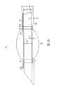
图3A示出了根据本发明构造的ETT19。ETT19包括中空管或管状构件19a和安装在管19a的远端附近的套囊或气囊20。并且,在ETT19中,中空管19a和套囊20都由硅树脂制成。用于制造中空管19a的硅树脂的硬度计标示(或硬度)大约是肖氏硬度A80。用来制造管19a的合适来源是德国的Dow Corning,Midland,Michigan,或Wacker Silicone。成人用的管19a的长度大约是30至40cm。Figure 3A shows an
使用硅树脂套囊20是有益的,因为,如上所述,硅树脂不具有类似于乳胶的过敏效果,并且硅树脂比乳胶寿命长。由于在现有技术中将硅树脂粘接硅树脂的方法是公知的,因此使用硅树脂管19a便于套囊20连接到管19a上。并且,如下所述,调节中空管19a和套囊20的尺寸,以在IPPV期间能充分地将气体供给到病人的肺部,并且保证套囊20在圆周地接触气管内的粘膜之前能达到压力稳定值。因此,ETT19便于测量粘膜压力并进一步便于避免产生过高的粘膜压力。并且,使用硅树脂套囊20能改善与气管的密封并避免产生与无弹性套囊类似的褶皱和微小泄漏。The use of a
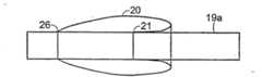
在ETT19中,套囊20安装到中空管19a的直径减小部分或区域32上。即,与管19a的其他部分的直径相比,管19a的区域32的外径减小了。图3B示出了该直径减小区域32的放大视图。如图所示,区域32的外径,即,OD1由中空管19a的其余部分的外径(OD2)减小而得。相反地,中空管19a的内径ID(或空气管腔的直径)从中空管19a的近端至远端基本保持恒定。由于中空管的外径的变化,中空管19a的区域32的壁厚T1小于中空管19a的其余部分的壁厚T2。充气管腔30限定在中空管19a的壁厚为T2的区域(即,在直径减小区域32之外的区域)的壁中。In the
如图所示,套囊20在区域32远端的位置24和26处安装到管19a上(即,位置24和26与区域32和区域32之外的管的其他部分之间的交界处邻近)。典型地,对于适用于成人尺寸的ETT而言,安装位置24和26之间的距离大约是3至5厘米。并且,相对短且硬的延伸管36从管腔30的内侧延伸,穿过套囊的安装位置24,并进入套囊20的内空间。因此,通过连接到充气管腔30的近端(邻近中空管19a的近端)上的气体供送装置,例如注射器来控制对套囊20的充气和放气。As shown,
由于中空管19a由硅树脂制成,因此管壁厚T2大于由更硬的材料(例如PVC)制成的管所要求的厚度值。因此,对于给定的内径ID,中空管19a的外径OD2大于由PVC制成的中空管19a所要求的外径。更大的中空管19a的外径OD2将会增加保证连接到管19a上的套囊在与气管内的粘膜圆周地接触之前达到压力稳定值的难度。但是,为了补偿由于使用硅树脂来制造管19a而引起管的外径增加,管19a具有直径减小区域32。将套囊20连接到直径减小区域32上将增加套囊在与气管内粘膜圆周地接触之前的膨胀量,并由此便于保证套囊在进行这种圆周接触之前能达到其压力稳定值。Since the
在适用于成人尺寸的ETT的一实施例中,管19a的内径ID大约是7毫米,壁厚T2大约是1.625毫米,区域32的壁厚T1大约是1.0毫米,管19a在区域32处的直径OD1大约是9毫米,且管19a的大部分的外径OD2大约是10.25毫米。套囊20的压力稳定值大约是30至35厘米水柱,且当套囊直径小于成人气管的最小预测直径(例如,小于约1.5厘米)时,套囊能达到压力稳定值。In one embodiment of an ETT suitable for adult sizes, the inner diameter ID of the
然而,在适用于成人尺寸的ETT的另一实施例中,管19a的内径ID大约是8毫米,壁厚T2大约是1.625毫米,区域32的壁厚T1大约是1.125毫米,且管19a在区域32处的外径OD1大约是10.25毫米,管19a的大部分的外径OD2大约是11.25毫米。此外,套囊20的压力稳定值大约是30至35厘米水柱,且当套囊直径小于成人气管的最小预测直径(例如,小于约1.5厘米)时,套囊20的压力能达到压力稳定值。However, in another embodiment of an ETT suitable for adult sizes, the inner diameter ID of the
如上所述,充气管腔30限定在中空管19a的壁厚为T2的区域(即,直径减小区域32之外的区域)的壁中。ETT19的一个特点是具有位于中空管19a的壁中的充气管腔30,该充气管腔30限制了管的最小壁厚。有利地,管腔30并没有延伸超过直径减小区域32,例如,管腔从管19a的近端附近向直径减小部分32延伸。相对短且硬的中空管36插入管腔30中,并通过气囊的安装位置24,从而使流体在管腔30和套囊20的内部之间流通。As described above, the
如果直径减小区域32的壁厚T1太薄,那么套囊20的内压(该压力圆周地施加到区域32的外壁上,并有效地向内挤压区域32)将足以使直径减小区域32破裂。当然不期望管19a的任一部分出现这样的破裂,由于这样将会引起ETT的空气管腔出现阻塞,从而阻止了向肺部进行通畅供气。防止这种破裂的一种方法是用肖氏硬度A大约是10的硅树脂制造套囊20。使用具有这样硬度的硅树脂套囊将会使压力稳定值保持在30至35厘米水柱那么低,该压力值在正常的手术条件下不会伤害气管粘膜也不会使管破裂。If the wall thickness T1 of the reduced-
图4示出了防止中空管19a破裂的另一方法,特别地,该方法防止直径减小区域32的破裂。图4示出了当套囊20被放气时本发明又一实施例中的ETT19的区域32的放大剖视图。在图4所示的实施例中,螺旋加固金属线或其他的加强构件42设置在中空管19a的壁中。加固金属线42增加了中空管19a的径向强度,并增加了管的抗碎强度,从而当套囊20被充气时,管19a不会破裂。优选地,加固金属线42位于邻近中空管19a的内表面的位置处。在此处设置加固金属线便于加固金属线42和空气供送管腔30设置在同一管19a中。加固金属线42沿中空管19a的整个长度延伸,或者替换地,加固金属线42仅设置在直径减小区域32的近端。FIG. 4 shows another method of preventing the
应了解许多制造方法可用于制造包括加固金属线42的管19a。例如,将直径减小管(即,一管,其内径ID等于管19a所期望的内径,其外径小于区域32的外径OD1)压制而成,然后将加固金属线42设置在管的外表面上。接着在直径减小管和金属线之上施加或压制第二管。第二管或外管被加热并与直径减小管连接于一体以形成单一的管19a。通过从管外表面的一部分去掉材料而形成直径减小区域32。例如,通过将管19a放置在车床上并从管外表面的一部分切削掉材料从而形成区域32。无论加固金属线是否设置在管中,这种制造技术都可以用来形成直径减小区域32。It should be appreciated that a number of manufacturing methods are available for manufacturing the
再次参见图3B,能看出管19a可以被制造成这样,即,充气管腔30从管19a的近端开始向邻近管19a的远端的位置30d延伸。通过车床或其他装置从管19a的一部分切削掉材料以形成直径减小区域32,从而自动地使充气管腔30在位置30e处与区域32连接,只要从管的外部切削掉足够的材料以暴露管腔30。之后,如上所述,使用硬管36将充气管腔30连接到套囊20的内部空间。Referring again to Figure 3B, it can be seen that the
图5示出了当套囊20被放气时本发明另一实施例中的ETT19的直径减小区域32的放大剖视图。如图所示,管19a的直径减小区域32的外表面的特征在于:该外表面上形成了条纹50或对该外表面进行了粗糙加工。条纹50有利地减小了套囊20粘接到管19a上的可能性。通常并不希望套囊20的任一部分(除了位置24、26之外,在该位置处套囊20连接到管19a上)粘接到管19a的外表面上,因为这种粘接通常将导致不能均匀地对套囊进行充气。对套囊20的不均匀充气是不希望的,因为这将使得与气管不能形成最佳的密封。Figure 5 shows an enlarged cross-sectional view of the reduced
在一优选实施例中,条纹50具有螺纹表面形式(例如,像螺钉的螺纹),条纹50包括一或多个刻入管19a的外表面中的螺旋凹槽。在一实施例中,该凹槽宽0.5毫米,深0.2毫米。例如,该凹槽可通过高速车床切削而成。条纹50是螺旋槽的优点是该条纹能迅速并均匀地将从管腔30引入的气体分配到套囊的整个内表面,从而对套囊20均匀充气。但是,应了解如果条纹50不采用螺旋凹槽的形式也可以。例如,条纹50不包括螺旋凹槽,而包括纵向随意的粗造面或随意的伪粗糙面。In a preferred embodiment, the
图6示出了当套囊20被充气时本发明另一实施例中的ETT的直径减小区域32的放大剖视图。在上述实施例中,位置24、26位于直径减小区域32(即,位置24、26位于管19a的外径是OD1的区域),套囊20在该位置24、26处与管19a连接。但是,如图6所示,位置24、26可以位于区域32之外(即,位置24、26可以位于管19a的外径是OD2的区域)。在该实施例中,可以没有半刚性延伸管36(例如,如图3B所示)。例如,形成套囊20的材料被预拉伸时采用图6所示的实施例,下面将详细描述。Figure 6 shows an enlarged cross-sectional view of the reduced
需要修整直径减小区域32和邻近区域32的管19a的部分,以使管19a具有光滑面,从而在插入和抽出ETT19的期间使对病人自身的气道的伤害减小到最低程度,例如,在图6所示的实施例中,ETT19的外径在位置24、26处稍稍增加从而干扰管19a的另外的光滑外表面,或者在管19a另外的光滑外表面上形成“凸阶”。为了去掉凸阶,期望在位置24、26处切削掉管19a的外表面的小部分,从而当连接套囊20时,ETT19的外表面光滑并在位置24、26处没有凸阶面。类似地,在图3B、4和6所示的实施例中,需要在邻近区域32处削尖管19a的外表面,从而光滑地改变外直径而没有形成凸阶。The reduced
如上所述,设有区域32增加了套囊20的膨胀量,从而增加了套囊20在圆周地接触气管内粘膜之前达到压力稳定值的可能性。因此,设有直径减小区域32便于粘膜压力的测量,并进一步便于避免产生过高的粘膜压力,这是由于使用与图2B相关的上述程序可用于测量由硅树脂套囊引起的粘膜压力。另一种增加套囊20在圆周地接触气管内粘膜之前达到压力稳定值的可能性的方法是:在将套囊20安装到管19a上之前预拉伸套囊20,从而即使对套囊进行完全放气时,套囊材料仍处于拉伸状态(即,超过其自然的固定尺寸)。这种拉伸或预拉伸将减小套囊在达到压力稳定值之前的必须拉伸的额外量。施加于套囊的预拉伸量是有限的。如果套囊被过度预拉伸,那么套囊将不能安全地膨胀至合适直径。并且,如果套囊使用附加的套囊材料可使套囊能膨胀至合适直径,套囊与管的连接的连接点之间会相隔很远。正如上述考虑那样,套囊的希望拉伸百分比范围是50%至100%。即,如果将线性长度为3厘米的套囊拉伸至6厘米,那么拉伸百分比是100%。尽管期望拉伸,但是过度拉伸将减小套囊的保存寿命。因此,本领域的技术人员能够理解在设计上最佳的拉伸量需要考虑保存寿命。As noted above, the presence of
在最后安装之前的拉伸套囊的方法中,套囊可以在未拉伸状态下安装在管19a上,然后对其充气,该套囊可以是由弹性材料制成的管状构件。然后沿管19a轴向地拉动已被充气的套囊以将管19a部分套入套囊中,从而套囊的一部分是“双层的”。然后将套囊的双层部分固定在管上。因此套囊以拉伸方式安装到管19a上。这增加了套囊在圆周地接触气管内粘膜之前达到压力稳定值的可能性。预拉伸套囊也能减小套囊粘接到管上的可能性。In the method of stretching the cuff prior to final installation, the cuff may be mounted on the
图7A-7C简要示出了预拉伸套囊20的方法。如图7A所示,开始将套囊材料20连接到管19a上并进行充气。此时,套囊的左端在位置26处连接到管19a上,套囊的右端在位置21处连接到管19a上。如图7B所示,然后纵向地向右拉动套囊以拉伸套囊材料。通过向右纵向地拉动套囊而拉伸套囊的步骤,例如可以手工地进行操作。如图7B所示,向右拉伸套囊将会使位置21处的连接点右侧的所有套囊材料变成“双层”。如图7C所示,然后朝管19a向内挤压套囊以使套囊材料的右端在位置24处接触管19a。然后,套囊材料的右端在位置24处连接到管19a上。从而有效地使位置24至26之间的所有套囊材料被纵向预拉伸。为了便于阐述,在图7A-7C所示中未示出直径减小区域32,但是,应理解可执行这里示出的步骤以使套囊20位于区域32内。7A-7C schematically illustrate a method of
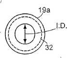
在与图7A-7C相关的上述方法中,在将套囊20安装到管19a上之前,纵向预拉伸套囊材料。作为纵向拉伸的变化形式,在将套囊20安装到管19a上之前,套囊材料也可以被圆周地拉伸。图8A和8B示出了这种圆周预拉伸。图8A示出了根据本发明构造的ETT的管19a的侧剖视图,该侧视图是沿图3B中的线9-9的大体方向剖取的。在图8A中,圆标记19a表示中空管19a(外径是OD2)的大部分的外圆周;虚线圆标记32表示管19a的直径减小区域32(外径是OD1)的外圆周;且圆32的内部(其直径被标记成ID)表示内管腔或空气通道,该内管腔从中空管19a的近端向远端延伸。在图8B中,圆标记20表示用来形成套囊20的弹性材料管,该图是沿与图8A横截面的大体相同的方向剖取的横截面。为了便于阐述,在图8A中未示出充气管腔30。如图所示,当套囊材料处于自然固定(未拉伸)状态时,其直径小于区域32的直径。所以,将套囊材料放置在整个管19a上并使套囊材料位于区域32中,将会有利地对套囊材料圆周地预拉伸。应理解套囊材料也可以同时圆周地和纵向地被预拉伸。In the method described above in relation to Figures 7A-7C, the cuff material is pre-stretched longitudinally prior to installation of the
图8A示出了同心地位于管19a之内的空气通道(其直径是ID)。但是,形成空气通道以使其偏心地位于管19a内也是有益的。图9示出了这种偏心设置的空气管腔的一示例。偏心设置能使管19a更容易地沿具有厚度增加的管的部分弯曲。当ETT19处于合适位置时,偏心设置能有助于减小施加到气管上的压力。为了便于阐述,与图8A一样,在图9中未示出充气管腔30。Figure 8A shows the air passage (whose diameter is ID) located concentrically within the
如上所述,优选地,管19a由硅树脂制成。但是,也可以使用其他材料。特别地,使用比硅树脂硬的材料(例如PVC)来制造管19a是有益的。与硅树脂管相比较,使用更硬的材料(例如PVC)来制造管19a将使区域32之外的管19a的外径OD1减小。在一实施例中,通过在管的一部分(套囊安装在管的该部分上)的长度上将外径减小10%,而使直径减小区域32形成在PVC管19a上。As mentioned above, preferably the
如上所述,将硅树脂套囊20粘接到PVC管19a上比将硅树脂套囊粘接到硅树脂管上更难。但是,可以使用热缩塑料材料将硅树脂套囊20连接到PVC管19a上。热缩塑料材料可以被构造成例如管或圆环,该热缩塑料在这两种材料之上收缩,从而将套囊20固定到管19a上。当使用热缩塑料材料将套囊20固定到管19a上时,在套囊20充气时套囊20将会纵向滚动或滑动。例如,参见图3B,当套囊20被充气,套囊20在位置24处趋于朝左(朝ETT19的近端)滚动或滑动。将位置24、26设置在直径减小区域32之内的优点是:任何一种这样的滚动或滑动都将会使热缩塑料材料邻接管19a的较厚部分(即,在壁厚为T2的部分),并且这种邻接趋于使热缩塑料材料固定在合适位置处。另外,由于热缩塑料材料会使厚度增加,因此在区域32和管19a的其余部分之间的连接处使“凸阶”或硬部分减小到最小或消除。因此,有利地,将位置24、26位于区域32的远端,从而位置24、26邻接管19a的较厚部分。但是,如图6所示,将位置24、26设置在区域32之外也是有益的。替换地,也可以使位置24、26中的一个位置位于区域32之内,而将另一位置处于区域32之外。As mentioned above, bonding the
另外,或者作为替换地,使用热缩塑料材料、其他方法(例如激光焊、热焊)、或使用粘接剂都可以将套囊20连接到中空管19a上。但是,使用热缩塑料材料优选地用来将硅树脂套囊粘接到PVC管上,而其他方法,例如焊接优选地用来将硅树脂套囊连接到硅树脂管上。Additionally, or alternatively,
上述描述意于提供根据权利要求所限定的装置的典型示例。在不脱离权利要求所限定的范围内可以对上述装置进行变化。上述描述及附图所示的内容都是阐述性的,而不是限制性的。例如,尽管已经详细地描述了ETT,但应了解本发明也同样适用于气管切开插管。同样,用来形成本发明的医疗装置的中空管或管状构件不需要是沿其整个长度具有均匀横截面的管。更确切地说,管状构件可以包括预先形成的弯曲部分,或角度(例如在气管切开插管的情况下)。并且,管状构件的直径减小区域或该区域之外的外径不需保持恒定。但是,至少直径减小区域的一部分的外径通常小于邻近于直径减小区域的管状构件部分的外径。并且,尽管已经分别单独地讨论了几种不同的方法和结构(例如,具有条纹的外表面、加固构件、预先拉伸),但是应了解这些方法和构件可以单独使用或者结合使用。例如,根据本发明构造的ETT可以包括加固金属线、具有条纹外表面的直径减小区域和预拉伸套囊。The above description is intended to provide a typical example of an arrangement as defined in the claims. Variations may be made in the arrangement described above without departing from the scope defined by the claims. The foregoing description and the contents shown in the accompanying drawings are illustrative rather than restrictive. For example, although the ETT has been described in detail, it should be understood that the invention is equally applicable to tracheostomy tubes. Likewise, the hollow tube or tubular member used to form the medical device of the present invention need not be a tube of uniform cross-section along its entire length. Rather, the tubular member may include a pre-formed bend, or angle (eg in the case of a tracheostomy tube). Also, the outer diameter of the tubular member need not remain constant at or outside the reduced diameter region. However, the outer diameter of at least a portion of the reduced diameter region is generally smaller than the outer diameter of the portion of the tubular member adjacent to the reduced diameter region. Also, while several different methods and configurations (eg, striated outer surface, reinforcing members, pre-stretching) have been discussed individually, it should be understood that these methods and members may be used alone or in combination. For example, an ETT constructed in accordance with the present invention may include reinforcing wires, a reduced diameter region with a striated outer surface, and a pre-tensioned cuff.
Claims (22)
Applications Claiming Priority (4)
| Application Number | Priority Date | Filing Date | Title |
|---|---|---|---|
| US35112802P | 2002-01-23 | 2002-01-23 | |
| US60/351,128 | 2002-01-23 | ||
| US10/144,397 | 2002-05-13 | ||
| US10/144,397US7360540B2 (en) | 2002-01-23 | 2002-05-13 | Endotracheal tube which permits accurate determination of mucosal pressure |
Publications (2)
| Publication Number | Publication Date |
|---|---|
| CN1620321A CN1620321A (en) | 2005-05-25 |
| CN100415316Ctrue CN100415316C (en) | 2008-09-03 |
Family
ID=26841963
Family Applications (1)
| Application Number | Title | Priority Date | Filing Date |
|---|---|---|---|
| CNB038026295AExpired - LifetimeCN100415316C (en) | 2002-01-23 | 2003-01-08 | Trachea cannula capable of accurately measuring mucosal pressure |
Country Status (16)
| Country | Link |
|---|---|
| US (1) | US7360540B2 (en) |
| EP (1) | EP1467792B1 (en) |
| JP (1) | JP4913987B2 (en) |
| KR (1) | KR100980761B1 (en) |
| CN (1) | CN100415316C (en) |
| AT (1) | ATE551089T1 (en) |
| AU (1) | AU2003236793B2 (en) |
| BR (1) | BRPI0307108B8 (en) |
| CA (1) | CA2473887C (en) |
| ES (1) | ES2395479T3 (en) |
| IL (1) | IL162985A (en) |
| MX (1) | MXPA04007131A (en) |
| NZ (1) | NZ534178A (en) |
| RU (1) | RU2314836C2 (en) |
| TW (1) | TWI252764B (en) |
| WO (1) | WO2003061747A1 (en) |
Families Citing this family (51)
| Publication number | Priority date | Publication date | Assignee | Title |
|---|---|---|---|---|
| US6079409A (en)* | 1997-07-25 | 2000-06-27 | Brain; Archibald Ian Jeremy | Intubating laryngeal mask |
| GB0218868D0 (en) | 2002-08-14 | 2002-09-25 | Nasir Muhammed A | Improved airway management device |
| WO2005016427A2 (en)* | 2003-08-14 | 2005-02-24 | Muhammed Aslam Nasir | Improved airway device |
| GB0411858D0 (en)* | 2004-05-27 | 2004-06-30 | Young Peter J | Device to facilitate airway suctioning |
| US7730888B2 (en)* | 2004-09-09 | 2010-06-08 | Spivan, Llc | Nasopharyngeal airway device and method of use |
| US7100612B2 (en)* | 2004-09-09 | 2006-09-05 | Epic Corporation | Nasopharyngeal airway device and method of use |
| US20060207603A1 (en)* | 2005-02-14 | 2006-09-21 | The Cleveland Clinic Foundation | Ventilator attachment for tracheal T-tubes |
| US20120180796A1 (en)* | 2005-03-19 | 2012-07-19 | Smiths Group Plc | Tracheostomy Tubes |
| US9243650B2 (en) | 2005-10-11 | 2016-01-26 | Steven C. Elsner | Fin array for use in a centrifugal fan |
| US20070289596A1 (en)* | 2006-06-14 | 2007-12-20 | Campbell Shannon E | Endotracheal cuff and technique for using the same |
| US8196584B2 (en) | 2006-06-22 | 2012-06-12 | Nellcor Puritan Bennett Llc | Endotracheal cuff and technique for using the same |
| US7654264B2 (en) | 2006-07-18 | 2010-02-02 | Nellcor Puritan Bennett Llc | Medical tube including an inflatable cuff having a notched collar |
| US8307830B2 (en)* | 2006-09-29 | 2012-11-13 | Nellcor Puritan Bennett Llc | Endotracheal cuff and technique for using the same |
| GB0623535D0 (en)* | 2006-11-25 | 2007-01-03 | Smiths Group Plc | Suction apparatus and connectors |
| GB0700045D0 (en)* | 2007-01-03 | 2007-02-07 | Smiths Group Plc | Cuffed medical tubes |
| GB2452776A (en)* | 2007-09-17 | 2009-03-18 | Internat Patents Inc | Method for monitoring an airway device such as an endotrachael tube |
| GB0810169D0 (en)* | 2008-06-04 | 2008-07-09 | Cosmeplast Ets | Improvements relating to respiratory interface devices |
| USD665495S1 (en) | 2009-07-14 | 2012-08-14 | Muhammed Aslam Nasir | Medical device |
| WO2011106754A1 (en) | 2010-02-27 | 2011-09-01 | King Systems Corporation | Laryngeal tube |
| US8555887B2 (en) | 2010-04-30 | 2013-10-15 | Covidien Lp | Tracheal tube with dividing membrane |
| GB201010647D0 (en) | 2010-06-24 | 2010-08-11 | Docsinnovent Ltd | Stopper device |
| US8602030B2 (en) | 2010-06-30 | 2013-12-10 | Covidien Lp | Tracheal tubes with improved secretion removal systems |
| USD693920S1 (en) | 2011-06-08 | 2013-11-19 | Intersurgical Ag | Airway device |
| USD665254S1 (en) | 2011-06-08 | 2012-08-14 | Intersurgical Ag | Airway device packaging |
| USD688787S1 (en) | 2011-06-08 | 2013-08-27 | Intersurgical Ag | Airway device cap and strap holder |
| US20130000649A1 (en)* | 2011-06-29 | 2013-01-03 | Nellcor Puritan Bennett Llc | Tracheal tube with controlled-profile cuff |
| USD712244S1 (en) | 2011-09-23 | 2014-09-02 | Intersurgical Ag | Medical device package |
| GB201201438D0 (en) | 2012-01-27 | 2012-03-14 | Docsinnovent Ltd | Improved stopper device |
| USD761952S1 (en) | 2012-07-27 | 2016-07-19 | Docsinnovent Limited | Airway device |
| US10569038B2 (en)* | 2012-07-06 | 2020-02-25 | The Regents Of The University Of California | Dual lumen endobronchial tube device |
| GB201303553D0 (en)* | 2013-02-28 | 2013-04-10 | Smiths Medical Int Ltd | Tracheostomy tube assemblies and inner cannulae |
| WO2015013378A1 (en)* | 2013-07-25 | 2015-01-29 | Medical Instrument Ventures, Llc | Cuffed tracheal tube |
| GB201319087D0 (en) | 2013-10-29 | 2013-12-11 | Indian Ocean Medical Inc | Artificial airway device |
| GB2546167B (en) | 2013-12-17 | 2018-02-28 | Aslam Nasir Muhammed | Intubating Airway Device |
| GB201405132D0 (en) | 2014-03-21 | 2014-05-07 | Indian Ocean Medical Inc | Fixation apparatus |
| US20160101253A1 (en)* | 2014-10-08 | 2016-04-14 | Husam Ibrahim ALAHMADI | Protective endotracheal tube |
| USD782658S1 (en) | 2015-02-02 | 2017-03-28 | Indian Ocean Medical Inc. | Airway device |
| USD1051359S1 (en) | 2015-06-15 | 2024-11-12 | Intersurgical Ag | Airway device |
| USD842456S1 (en) | 2015-12-15 | 2019-03-05 | Intersurgical Ag | Airway device |
| CN105477758A (en)* | 2016-01-29 | 2016-04-13 | 青岛大学附属医院 | Novel trachea cannula |
| CN105797252B (en)* | 2016-05-27 | 2019-07-09 | 熊振天 | A kind of double-lumen catheter localization method, device and conduit |
| DE102016120822A1 (en) | 2016-11-02 | 2018-05-03 | Tracoe Medical Gmbh | Bendable tracheostomy device |
| US20180272090A1 (en)* | 2017-03-27 | 2018-09-27 | Hansa Medical Products, Inc. | System and method for protecting a patient's tracheal wall during percutaneous procedures |
| JP6924890B2 (en)* | 2017-07-05 | 2021-08-25 | テレフレックス ライフ サイエンシーズ アンリミテッド カンパニー | Mechanical user control elements for fluid input modules |
| USD848609S1 (en)* | 2017-11-21 | 2019-05-14 | Board Of Regents, The University Of Texas System | Endotracheal tube |
| GB201720733D0 (en) | 2017-12-13 | 2018-01-24 | Ashkal Development Ltd | Airway device |
| US20220118205A1 (en)* | 2018-09-25 | 2022-04-21 | Airway Medix S.A. | Ventilation tubes with inflatable cuffs |
| JP1649726S (en) | 2019-01-18 | 2020-01-14 | ||
| CN110064123B (en)* | 2019-03-28 | 2024-06-07 | 暨南大学 | Stomach tube guide tube special for laparoscopic sleeve gastrectomy |
| USD1025348S1 (en) | 2020-04-16 | 2024-04-30 | Intersurgical Ag | Airway device |
| GB202318479D0 (en)* | 2023-12-04 | 2024-01-17 | Smiths Medical | Cuffed medico-surgical tubes |
Citations (5)
| Publication number | Priority date | Publication date | Assignee | Title |
|---|---|---|---|---|
| US3734100A (en)* | 1973-05-07 | 1973-05-22 | Medical Products Corp | Catheter tubes |
| US5957134A (en)* | 1997-11-18 | 1999-09-28 | Lee; Han Shik | Anesthesia delivery system |
| CN2348861Y (en)* | 1998-10-22 | 1999-11-17 | 杜长军 | Blind plugging type tracheal tube |
| CN1274294A (en)* | 1997-10-08 | 2000-11-22 | 钟渊化学工业株式会社 | Balloon catheter and method of prodn. thereof |
| EP1121955A2 (en)* | 2000-01-19 | 2001-08-08 | Cordis Neurovascular, Inc. | Inflatable balloon catheter seal and method |
Family Cites Families (14)
| Publication number | Priority date | Publication date | Assignee | Title |
|---|---|---|---|---|
| US3407817A (en) | 1965-07-26 | 1968-10-29 | Air Reduction Inc | Catheter with cuff inflater and indicator |
| US3884242A (en)* | 1971-03-29 | 1975-05-20 | Mpc Kurgisil | Catheter assembly |
| GB1399093A (en) | 1971-06-11 | 1975-06-25 | Matburn Holdings Ltd | Nasal tracheal tubes |
| DK625174A (en)* | 1974-12-02 | 1976-06-03 | V N F Lomholt | RESPIRATORY CATHETER |
| US4341210A (en)* | 1978-09-15 | 1982-07-27 | Elam James O | Cuffed endotracheal tube and method |
| JP2736896B2 (en)* | 1988-07-18 | 1998-04-02 | テルモ株式会社 | Balloon catheter |
| JPH0349398U (en)* | 1989-09-20 | 1991-05-14 | ||
| US5447497A (en)* | 1992-08-06 | 1995-09-05 | Scimed Life Systems, Inc | Balloon catheter having nonlinear compliance curve and method of using |
| GB9411215D0 (en)* | 1994-06-04 | 1994-07-27 | Brain Archibald Ian Jeremy | A fibreoptic intubating laryngeal mask airway |
| DE19547538C2 (en)* | 1995-12-20 | 1999-09-23 | Ruesch Willy Ag | Instrument for use in interventional flexible tracheoscopy / bronchoscopy |
| US5792144A (en)* | 1997-03-31 | 1998-08-11 | Cathco, Inc. | Stent delivery catheter system |
| GB2324735B (en) | 1997-04-28 | 2001-06-20 | George Downward | A device to seal the trachea in the intubated patient |
| US6093142A (en)* | 1998-04-30 | 2000-07-25 | Medtronic Inc. | Device for in vivo radiation delivery and method for delivery |
| CA2468108A1 (en)* | 1999-09-27 | 2003-06-05 | Merlyn Associates, Inc. | Endotracheal tube with tip directional control and position preserving mechanism |
- 2002
- 2002-05-13USUS10/144,397patent/US7360540B2/ennot_activeExpired - Lifetime
- 2003
- 2003-01-08NZNZ534178Apatent/NZ534178A/ennot_activeIP Right Cessation
- 2003-01-08BRBRPI0307108Apatent/BRPI0307108B8/ennot_activeIP Right Cessation
- 2003-01-08ESES03731667Tpatent/ES2395479T3/ennot_activeExpired - Lifetime
- 2003-01-08JPJP2003561687Apatent/JP4913987B2/ennot_activeExpired - Lifetime
- 2003-01-08ATAT03731667Tpatent/ATE551089T1/enactive
- 2003-01-08CACA2473887Apatent/CA2473887C/ennot_activeExpired - Lifetime
- 2003-01-08EPEP03731667Apatent/EP1467792B1/ennot_activeExpired - Lifetime
- 2003-01-08AUAU2003236793Apatent/AU2003236793B2/ennot_activeExpired
- 2003-01-08CNCNB038026295Apatent/CN100415316C/ennot_activeExpired - Lifetime
- 2003-01-08KRKR1020047011478Apatent/KR100980761B1/ennot_activeExpired - Fee Related
- 2003-01-08RURU2004122627/14Apatent/RU2314836C2/ennot_activeIP Right Cessation
- 2003-01-08MXMXPA04007131Apatent/MXPA04007131A/enactiveIP Right Grant
- 2003-01-08WOPCT/EP2003/000105patent/WO2003061747A1/enactiveApplication Filing
- 2003-01-16TWTW092100920Apatent/TWI252764B/ennot_activeIP Right Cessation
- 2004
- 2004-07-12ILIL162985Apatent/IL162985A/ennot_activeIP Right Cessation
Patent Citations (5)
| Publication number | Priority date | Publication date | Assignee | Title |
|---|---|---|---|---|
| US3734100A (en)* | 1973-05-07 | 1973-05-22 | Medical Products Corp | Catheter tubes |
| CN1274294A (en)* | 1997-10-08 | 2000-11-22 | 钟渊化学工业株式会社 | Balloon catheter and method of prodn. thereof |
| US5957134A (en)* | 1997-11-18 | 1999-09-28 | Lee; Han Shik | Anesthesia delivery system |
| CN2348861Y (en)* | 1998-10-22 | 1999-11-17 | 杜长军 | Blind plugging type tracheal tube |
| EP1121955A2 (en)* | 2000-01-19 | 2001-08-08 | Cordis Neurovascular, Inc. | Inflatable balloon catheter seal and method |
Also Published As
| Publication number | Publication date |
|---|---|
| PL371249A1 (en) | 2005-06-13 |
| US7360540B2 (en) | 2008-04-22 |
| TWI252764B (en) | 2006-04-11 |
| KR100980761B1 (en) | 2010-09-10 |
| CA2473887C (en) | 2010-09-14 |
| EP1467792B1 (en) | 2012-03-28 |
| BR0307108A (en) | 2004-12-28 |
| BRPI0307108B8 (en) | 2021-06-22 |
| NZ534178A (en) | 2007-05-31 |
| CA2473887A1 (en) | 2003-07-31 |
| KR20040078134A (en) | 2004-09-08 |
| US20030136413A1 (en) | 2003-07-24 |
| RU2314836C2 (en) | 2008-01-20 |
| MXPA04007131A (en) | 2005-05-16 |
| JP2005515040A (en) | 2005-05-26 |
| EP1467792A1 (en) | 2004-10-20 |
| ES2395479T3 (en) | 2013-02-13 |
| TW200302117A (en) | 2003-08-01 |
| CN1620321A (en) | 2005-05-25 |
| RU2004122627A (en) | 2005-04-10 |
| BRPI0307108B1 (en) | 2017-05-09 |
| WO2003061747A1 (en) | 2003-07-31 |
| ATE551089T1 (en) | 2012-04-15 |
| JP4913987B2 (en) | 2012-04-11 |
| IL162985A (en) | 2011-09-27 |
| AU2003236793B2 (en) | 2008-06-05 |
Similar Documents
| Publication | Publication Date | Title |
|---|---|---|
| CN100415316C (en) | Trachea cannula capable of accurately measuring mucosal pressure | |
| AU2003236793A1 (en) | An endotracheal tube which permits accurate determination of mucosal pressure | |
| US3734100A (en) | Catheter tubes | |
| JP4644673B2 (en) | Respiratory aid | |
| US3890976A (en) | Catheter tip assembly | |
| US5620408A (en) | Endoscopic over-tube | |
| US3460541A (en) | Endotracheal intubation tubes | |
| US8833373B2 (en) | Nasally inserted airway opening device for obstructive sleep apnea treatment | |
| US20110073115A1 (en) | Tracheal cuff for providing seal with reduced pressure on the tracheal walls | |
| US4248222A (en) | Endotracheal tube having a relief valve | |
| JP2000167060A (en) | Cuffed tube | |
| US10173022B1 (en) | Laryngeal mask cuff | |
| US10369311B2 (en) | Laryngeal mask cuff | |
| WO2012087841A1 (en) | Endotracheal tube having a cuff elastically expandable and non-elastically expandable portions and method of making and/or using the same | |
| CN213131409U (en) | Inflatable tracheal catheter | |
| US20170087318A1 (en) | Cuffed tubes | |
| CN209645616U (en) | Scope guiding tube | |
| CN209019682U (en) | Endotracheal tube with continuous inflation | |
| GB2225955A (en) | Pharyngeal airway | |
| CN221618245U (en) | Variable-diameter tracheal catheter adapting to trachea | |
| CN204411458U (en) | Automatic pressure-reducing air bags three cavities airway | |
| JP2021514284A (en) | Catheter inflatable cuff pressure ballast | |
| PL203659B1 (en) | An endotracheal tube, enabling an accurate determination of mucosal pressure, and a method of producing an endotracheal tube, enabling an accurate determination of mucosal pressure | |
| CN111904674A (en) | Adjustable esophageal dilator | |
| CN114904108A (en) | Laryngeal mask with good sealing performance, small damage and easiness in insertion and using method thereof |
Legal Events
| Date | Code | Title | Description |
|---|---|---|---|
| C06 | Publication | ||
| PB01 | Publication | ||
| C10 | Entry into substantive examination | ||
| SE01 | Entry into force of request for substantive examination | ||
| C14 | Grant of patent or utility model | ||
| GR01 | Patent grant | ||
| ASS | Succession or assignment of patent right | Owner name:INDIAN OCEAN MEDICAL CO., LTD. Free format text:FORMER OWNER: BRAIN ARCHIBALD IAN JEREMY Effective date:20140103 | |
| C41 | Transfer of patent application or patent right or utility model | ||
| TR01 | Transfer of patent right | Effective date of registration:20140103 Address after:Seychelles Mahe Patentee after:India Ocean Medical Co.,Ltd. Address before:Seychelles Mahe Patentee before:BRAIN ARCHIBALD IAN JEREMY | |
| CX01 | Expiry of patent term | ||
| CX01 | Expiry of patent term | Granted publication date:20080903 |