CN100414694C - Flat plate heat transfer device and manufacturing method thereof - Google Patents
Flat plate heat transfer device and manufacturing method thereofDownload PDFInfo
- Publication number
- CN100414694C CN100414694CCNB031586430ACN03158643ACN100414694CCN 100414694 CCN100414694 CCN 100414694CCN B031586430 ACNB031586430 ACN B031586430ACN 03158643 ACN03158643 ACN 03158643ACN 100414694 CCN100414694 CCN 100414694C
- Authority
- CN
- China
- Prior art keywords
- plate
- wick
- heat transfer
- transfer device
- lower plate
- Prior art date
- Legal status (The legal status is an assumption and is not a legal conclusion. Google has not performed a legal analysis and makes no representation as to the accuracy of the status listed.)
- Expired - Fee Related
Links
Images


Classifications
- F—MECHANICAL ENGINEERING; LIGHTING; HEATING; WEAPONS; BLASTING
- F28—HEAT EXCHANGE IN GENERAL
- F28D—HEAT-EXCHANGE APPARATUS, NOT PROVIDED FOR IN ANOTHER SUBCLASS, IN WHICH THE HEAT-EXCHANGE MEDIA DO NOT COME INTO DIRECT CONTACT
- F28D15/00—Heat-exchange apparatus with the intermediate heat-transfer medium in closed tubes passing into or through the conduit walls ; Heat-exchange apparatus employing intermediate heat-transfer medium or bodies
- F28D15/02—Heat-exchange apparatus with the intermediate heat-transfer medium in closed tubes passing into or through the conduit walls ; Heat-exchange apparatus employing intermediate heat-transfer medium or bodies in which the medium condenses and evaporates, e.g. heat pipes
- F28D15/0233—Heat-exchange apparatus with the intermediate heat-transfer medium in closed tubes passing into or through the conduit walls ; Heat-exchange apparatus employing intermediate heat-transfer medium or bodies in which the medium condenses and evaporates, e.g. heat pipes the conduits having a particular shape, e.g. non-circular cross-section, annular
- F—MECHANICAL ENGINEERING; LIGHTING; HEATING; WEAPONS; BLASTING
- F28—HEAT EXCHANGE IN GENERAL
- F28D—HEAT-EXCHANGE APPARATUS, NOT PROVIDED FOR IN ANOTHER SUBCLASS, IN WHICH THE HEAT-EXCHANGE MEDIA DO NOT COME INTO DIRECT CONTACT
- F28D15/00—Heat-exchange apparatus with the intermediate heat-transfer medium in closed tubes passing into or through the conduit walls ; Heat-exchange apparatus employing intermediate heat-transfer medium or bodies
- F28D15/02—Heat-exchange apparatus with the intermediate heat-transfer medium in closed tubes passing into or through the conduit walls ; Heat-exchange apparatus employing intermediate heat-transfer medium or bodies in which the medium condenses and evaporates, e.g. heat pipes
- F28D15/04—Heat-exchange apparatus with the intermediate heat-transfer medium in closed tubes passing into or through the conduit walls ; Heat-exchange apparatus employing intermediate heat-transfer medium or bodies in which the medium condenses and evaporates, e.g. heat pipes with tubes having a capillary structure
- F28D15/046—Heat-exchange apparatus with the intermediate heat-transfer medium in closed tubes passing into or through the conduit walls ; Heat-exchange apparatus employing intermediate heat-transfer medium or bodies in which the medium condenses and evaporates, e.g. heat pipes with tubes having a capillary structure characterised by the material or the construction of the capillary structure
- H—ELECTRICITY
- H01—ELECTRIC ELEMENTS
- H01L—SEMICONDUCTOR DEVICES NOT COVERED BY CLASS H10
- H01L23/00—Details of semiconductor or other solid state devices
- H01L23/34—Arrangements for cooling, heating, ventilating or temperature compensation ; Temperature sensing arrangements
- H01L23/42—Fillings or auxiliary members in containers or encapsulations selected or arranged to facilitate heating or cooling
- H01L23/427—Cooling by change of state, e.g. use of heat pipes
- F—MECHANICAL ENGINEERING; LIGHTING; HEATING; WEAPONS; BLASTING
- F28—HEAT EXCHANGE IN GENERAL
- F28F—DETAILS OF HEAT-EXCHANGE AND HEAT-TRANSFER APPARATUS, OF GENERAL APPLICATION
- F28F2210/00—Heat exchange conduits
- F28F2210/02—Heat exchange conduits with particular branching, e.g. fractal conduit arrangements
- F—MECHANICAL ENGINEERING; LIGHTING; HEATING; WEAPONS; BLASTING
- F28—HEAT EXCHANGE IN GENERAL
- F28F—DETAILS OF HEAT-EXCHANGE AND HEAT-TRANSFER APPARATUS, OF GENERAL APPLICATION
- F28F2245/00—Coatings; Surface treatments
- F28F2245/02—Coatings; Surface treatments hydrophilic
- H—ELECTRICITY
- H01—ELECTRIC ELEMENTS
- H01L—SEMICONDUCTOR DEVICES NOT COVERED BY CLASS H10
- H01L2924/00—Indexing scheme for arrangements or methods for connecting or disconnecting semiconductor or solid-state bodies as covered by H01L24/00
- H01L2924/0001—Technical content checked by a classifier
- H01L2924/0002—Not covered by any one of groups H01L24/00, H01L24/00 and H01L2224/00
Landscapes
- Engineering & Computer Science (AREA)
- Physics & Mathematics (AREA)
- General Engineering & Computer Science (AREA)
- Thermal Sciences (AREA)
- Sustainable Development (AREA)
- Mechanical Engineering (AREA)
- Life Sciences & Earth Sciences (AREA)
- Condensed Matter Physics & Semiconductors (AREA)
- General Physics & Mathematics (AREA)
- Computer Hardware Design (AREA)
- Microelectronics & Electronic Packaging (AREA)
- Power Engineering (AREA)
- Cooling Or The Like Of Semiconductors Or Solid State Devices (AREA)
- Cooling Or The Like Of Electrical Apparatus (AREA)
- Heat-Exchange Devices With Radiators And Conduit Assemblies (AREA)
Abstract
Translated fromChinese
Description
Translated fromChinese技术领域technical field
本发明涉及一种小尺寸的传热装置,更具体地是涉及用于冷却高发热芯片的平板传热装置。The invention relates to a small-sized heat transfer device, and more particularly relates to a flat plate heat transfer device for cooling high-heat-generating chips.
背景技术Background technique
由于半导体技术和制造半导体装置技术的飞速发展,超细小的电子装置得到了广泛使用,这些超细小的电子装置例如为具有更小厚度和体积、展示了更加卓越性能的膝上型电脑。在超细小的电子装置中,冷却具有更高热值的高发热元件很重要,该高发热元件例如为安装在计算机中的CPU芯片及整个装置。在确定整个装置是否能运转中,电子装置中的大多数高发热元件被认为是重要的。因此,除非从这些高发热元件产生的热被尽可能快地散掉,否则高发热元件的功能将相当大地退化。在更糟糕的情况中,高发热元件可能被完全损坏,在这种情况中,整个装置可能根本不运转。Due to the rapid development of semiconductor technology and the technology of manufacturing semiconductor devices, ultra-small electronic devices are widely used, such as laptop computers with smaller thickness and volume and exhibiting more excellent performance. In ultra-small electronic devices, it is very important to cool high heat-generating components with higher calorific value, such as CPU chips installed in computers and the entire device. Most high heat generating components in an electronic device are considered important in determining whether the entire device will function. Therefore, unless the heat generated from these high-heat-generating elements is dissipated as quickly as possible, the functions of the high-heat-generating elements will degrade considerably. In a worse case, the high heat generating element may be completely damaged, in which case the entire device may not function at all.
近年来,随着对冷却高发热元件重要性了解的增长,提供了各种用于冷却高发热元件的冷却器。In recent years, as awareness of the importance of cooling high heat generating components has grown, various coolers for cooling high heat generating components have been provided.
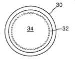
图1至3是传统圆柱热管的剖面图。特别地,图1表示一种在其内部形成槽12的圆柱热管10。图2表示了内部具有烧结金属22的圆柱热管20。图3表示的是内部具有网筛32的圆柱热管30。1 to 3 are cross-sectional views of conventional cylindrical heat pipes. In particular, FIG. 1 shows a
参见图1,被热源(未示出)产生的热量气化的蒸气经热管10中的空腔14被传送到冷凝部(未示出)。由冷凝部提供的液相冷却剂通过槽12流回蒸发部(未示出)。Referring to FIG. 1 , steam vaporized by heat generated by a heat source (not shown) is transferred to a condensation part (not shown) through a
图2和图3中的空腔24和34分别具有和图1中所示空腔14同样的功能。另外,图2和图3中所示的烧结金属22和网筛32的功能也分别和图1中的槽12相对应。The
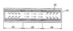
如图4所示,蒸发部44位于圆柱热管40的一端以与热源相接触,用于压缩蒸气的冷凝部48位于圆柱热管40的另一端。附图标记46代表连接在蒸发部44和冷凝部48之间的蒸气通路。热管40中的箭头代表冷却剂的运动方向。通过蒸气通路46进入冷凝部48的蒸气变为液相冷却剂。液相冷却剂透过位于热管40内部的多孔材料42,并在多孔材料42中的毛细作用下移动到蒸发部44。替代多孔材料42,图1到3所示的圆柱热管分别包括槽12、烧结金属22和网筛32。As shown in FIG. 4 , the
图1到3所示的圆柱热管可以被用在如膝上型电脑的超细小的电子装置中,在这种情况下,热管必须被压缩成具有更小的厚度,并被弯曲以增加冷凝部48中风扇热传递面积。尽管热管可被弯曲,但是,弯曲被压缩成具有较小厚度的热管是困难的,因为位于热管内部的毛细装置可能会物理变形,因此可能使热管的性能下降。Cylindrical heat pipes as shown in Figures 1 to 3 can be used in ultra-small electronic devices such as laptop computers, in which case the heat pipe must be compressed to have a smaller thickness and bent to increase condensation The heat transfer area of the fan in
同时,图1到3所示的每个热管内部具有的毛细结构可以被用在超细小的热管中。然而,当把图1中的槽12用在这种超细小热管中时,热管的制造成本上升了,因为在超细小热管中形成精密细槽是非常困难的。如果图2和图3中的烧结金属22或网筛32分别用在超细小热管的毛细结构中时,因为毛细层变薄,流动压降变得极大。另外,因为小孔的尺寸是不规则的,冷却剂的表面张力减弱。最终,热管的冷却效率降低了。Meanwhile, the capillary structure inside each heat pipe shown in FIGS. 1 to 3 can be used in ultrafine heat pipes. However, when the
发明内容Contents of the invention
本发明提供一种适用于超细小电子装置的具有毛细结构的平板传热装置,该装置降低了制造成本,并且蒸发热阻小。The invention provides a flat plate heat transfer device with a capillary structure suitable for ultra-small electronic devices, the device reduces the manufacturing cost and has small evaporation heat resistance.
本发明还提供一种制造平板传热装置的方法。The invention also provides a method of manufacturing the flat heat transfer device.
根据本发明的一个方面,提供一种平板传热装置,该装置包括一个蒸发部,一个冷凝部,液相冷却剂在蒸发部蒸发,在蒸发部产生的蒸气在冷凝部冷凝成液体,液相冷却剂借助于毛细作用力从冷凝部移动到蒸发部。所述平板传热装置包括上板、下板、毛细板和液相冷却剂。下板底部和热源相接触。上板和下板沿着其边缘密封联接以在上板和下板之间形成空隙。毛细板不与所述上板接触,位于上板和下板之间,并通过液相冷却剂的表面张力贴附在下板上。液相冷却剂在蒸发部和冷却部之间循环,把热源传来的热量从蒸发部传递到冷凝部。这里,毛细板包括多个孔和多个平面吸液芯,并使液相冷却剂借助于毛细板和下板之间的毛细作用力从冷凝部向蒸发部流动,其中,平面吸液芯存在于孔之间,并且蒸气穿过所述孔并且通过上板和毛细板之间的蒸气移动空间转移到冷凝部。According to one aspect of the present invention, a flat-plate heat transfer device is provided, which includes an evaporating part and a condensing part, the liquid-phase coolant evaporates in the evaporating part, and the vapor generated in the evaporating part condenses into a liquid in the condensing part, and the liquid phase The coolant moves from the condensing part to the evaporating part by means of capillary force. The flat plate heat transfer device includes an upper plate, a lower plate, a capillary plate and a liquid coolant. The bottom of the lower plate is in contact with the heat source. The upper and lower plates are sealingly coupled along their edges to form a void between the upper and lower plates. The capillary plate is not in contact with the upper plate, is located between the upper plate and the lower plate, and is attached to the lower plate by the surface tension of the liquid-phase coolant. The liquid-phase coolant circulates between the evaporating part and the cooling part, and transfers the heat from the heat source from the evaporating part to the condensing part. Here, the capillary plate includes a plurality of holes and a plurality of planar wicks, and makes the liquid-phase coolant flow from the condensing part to the evaporating part by means of the capillary force between the capillary plate and the lower plate, wherein the planar wicks exist between the holes, and the vapor passes through the holes and is transferred to the condensation part through the vapor moving space between the upper plate and the capillary plate.
优选的是,上板被压纹加工以具有凹部和突出部,并且上板的凹部和一些平面吸液芯接触以使毛细板贴附到下板上,该凹部是凸向毛细板的部分。Preferably, the upper plate is embossed to have recesses and protrusions, and the recesses of the upper plate contact some of the planar wicks to attach the capillary plate to the lower plate, the recesses being the portion protruding towards the capillary plate.
优选的是,平板传热装置还包括垂直隔片(spacer),所述隔片形成在上板的内侧壁上,以在上板和被上板围绕的元件之间形成间隙。Preferably, the flat plate heat transfer device further includes vertical spacers formed on inner side walls of the upper plate to form gaps between the upper plate and elements surrounded by the upper plate.
优选的是,设置到所述隔板的所述多个隔片的高度从冷凝部到蒸发部逐渐减小。Preferably, the heights of the plurality of partitions provided to the partition gradually decrease from the condensation part to the evaporation part.
优选的是,所述隔片集成在所述下板上从而在下板上形成隔片突起,在从冷凝部到蒸发部的范围的下板上,从集成了隔片的下板延伸的隔片突起的高度逐渐减少。Preferably, the spacer is integrated on the lower plate so as to form a spacer protrusion on the lower plate, and on the lower plate in the range from the condensation part to the evaporation part, the spacer extending from the lower plate integrated with the spacer The height of the protrusions gradually decreases.
优选的是,和上板接触的突起从毛细板延伸出,以使毛细板牢固地接触下板。Preferably, the protrusion contacting the upper plate extends from the capillary plate so that the capillary plate firmly contacts the lower plate.
优选的是,具有比平面吸液芯更小宽度的微型结构形成在下板的表面上。Preferably, microstructures having a smaller width than the planar wick are formed on the surface of the lower plate.
根据本发明的另一个方面,提供一种制造平板传热装置的方法,该平板传热装置包括蒸发部和冷凝部,液相冷却剂在蒸发部蒸发,在蒸发部产生的蒸气在冷凝部冷凝成液体,液相冷却剂借助于毛细作用力从冷凝部移动到蒸发部。该方法包括(1)形成一个下板,下板的底面和热源接触;(2)对应下板形成一个上板,这样,当使下板和上板联接时就在安装于上板和下板中的元件之间形成蒸气移动空间;(3)形成具有多个平面吸液芯和多个孔的毛细板,使液相冷却剂从冷凝部移动到蒸发部,其中毛细板不与所述上板接触,所述平面吸液芯存在于所述孔之间,并且蒸气穿过所述孔并且通过上板和毛细板之间的蒸气移动空间转移到冷凝部;(4)把毛细板安装在下板的预定区域中;(5)把上板布置在装有毛细板的下板上方;(6)联接上板和下板;(7)在联接的上板和下板之间注入液相冷却剂。According to another aspect of the present invention, there is provided a method for manufacturing a flat-plate heat transfer device, the flat-plate heat transfer device includes an evaporation part and a condensation part, the liquid-phase coolant evaporates in the evaporation part, and the vapor generated in the evaporation part is condensed in the condensation part The liquid coolant moves from the condensing part to the evaporating part by means of capillary force. The method includes (1) forming a lower plate, the bottom surface of which is in contact with a heat source; (2) forming an upper plate corresponding to the lower plate, so that when the lower plate and the upper plate are connected, they are mounted on the upper plate and the lower plate (3) form a capillary plate with a plurality of planar liquid-absorbing cores and a plurality of holes, so that the liquid-phase coolant moves from the condensing part to the evaporating part, wherein the capillary plate is not in contact with the upper plate contact, the planar liquid wick exists between the holes, and the vapor passes through the holes and is transferred to the condensation part through the vapor movement space between the upper plate and the capillary plate; (4) the capillary plate is installed on the lower (5) arrange the upper plate above the lower plate equipped with the capillary plate; (6) connect the upper plate and the lower plate; (7) inject liquid phase cooling between the connected upper plate and the lower plate agent.
优选的是,在步骤(1)中,使下板的预定区域凹进预定深度以安装毛细板。Preferably, in step (1), a predetermined area of the lower plate is recessed to a predetermined depth to install the capillary plate.
优选的是,在步骤(3)中,在毛细板上朝向上板形成毛细板突起,这样这些突起就和毛细板形成一体。Preferably, in step (3), capillary plate protrusions are formed on the capillary plate toward the upper plate so that these protrusions are integrated with the capillary plate.
优选的是,在步骤(2)中,在对应于蒸发部和冷凝部的上板部分中的一个处形成突起,这样使毛细板贴附到下板上。Preferably, in step (2), a protrusion is formed at one of the upper plate portions corresponding to the evaporating portion and the condensing portion, so that the capillary plate is attached to the lower plate.
该方法还包括形成具有多个隔片的隔板,用于在毛细板和下板之间均匀地保持一间隙,并把隔板安装在毛细板和下板之间。The method also includes forming a spacer having a plurality of spacers for uniformly maintaining a gap between the capillary plate and the lower plate, and installing the spacer between the capillary plate and the lower plate.
优选的是,多个隔片具有逐渐降低的高度,这样这些隔片在冷凝部的高度高于它们在蒸发部的高度。Preferably, the plurality of partitions have a gradually decreasing height such that the partitions are at a higher height in the condensation section than they are in the evaporation section.
优选的是,该方法还包括形成用于使毛细板附着到下板上的弹性元件,并把该弹性元件安装在上板和毛细板之间。Preferably, the method further includes forming an elastic member for attaching the capillary plate to the lower plate, and mounting the elastic member between the upper plate and the capillary plate.
优选的是,在毛细板的形成中,在多个平面吸液芯中的至少一些之间形成桥接。Preferably, bridges are formed between at least some of the plurality of planar wicks in the formation of the capillary sheets.
优选的是,在从多个平面吸液芯中选取的一个平面吸液芯面对下板的内表面上形成突起。Preferably, the protrusion is formed on an inner surface of one of the planar wicks selected from among the plurality of planar wicks facing the lower plate.
优选的是,在多个隔片中的至少一些之间形成隔片桥接。Preferably, spacer bridges are formed between at least some of the plurality of spacers.
优选的是,在步骤(3)中,利用湿蚀、干蚀、或冲压的方法形成多个平面吸液芯或多个孔。Preferably, in step (3), a plurality of planar liquid-absorbent cores or a plurality of holes are formed by means of wet etching, dry etching, or stamping.
优选的是,在步骤(6)中,利用焊接、铜焊、静电联接或热联接的方法联接上板和下板。Preferably, in step (6), the upper plate and the lower plate are joined by means of welding, brazing, electrostatic coupling or thermal coupling.
优选的是,将多个平面吸液芯或孔排列成直线状、放射状或网筛状。Preferably, a plurality of planar liquid-absorbent cores or holes are arranged in a linear, radial or mesh shape.
优选的是,将对应于蒸发部和冷凝部的上板压纹,以形成凹进区和突起区,这样蒸气能顺畅移动,向着毛细板突出的凹进区和多个平面吸液芯中的至少一些接触。Preferably, the upper plate corresponding to the evaporating part and the condensing part is embossed to form a recessed area and a raised area so that the vapor can move smoothly, and the recessed area protruding toward the capillary plate and the plurality of planar liquid-absorbing wicks At least some contact.
优选的是,在下板的表面上形成微型结构,这样来扩大下板的表面积。Preferably, microstructures are formed on the surface of the lower plate, thus enlarging the surface area of the lower plate.
优选的是,在下板上形成隔片突起,该隔片突起向上突出,这样它们就可以和下板形成一体。Preferably, spacer protrusions are formed on the lower plate, and the spacer protrusions protrude upward so that they can be integrally formed with the lower plate.
优选的是,隔片突起的高度在从冷凝部到蒸发部范围的下板上逐渐减小。Preferably, the height of the spacer protrusions gradually decreases on the lower plate ranging from the condensing part to the evaporating part.
优选的是,在将毛细板安装在该下板上之前,在下板要安装毛细板的区域上覆盖一层亲水膜。Preferably, before installing the capillary plate on the lower plate, a layer of hydrophilic film is covered on the area of the lower plate where the capillary plate is to be installed.
优选的是,在上板的内侧壁处形成垂直隔片,这样在上板和毛细板之间形成一个间隙。Preferably, vertical spacers are formed at the inner side walls of the upper plate, thus forming a gap between the upper plate and the capillary plate.
优选的是,该方法还包括在上板的内表面上形成一个和上板的材料不同的材料层。Preferably, the method further includes forming a layer of a material different from that of the upper plate on the inner surface of the upper plate.
优选的是,该方法还包括,面对上板,在下板的整个表面上形成一个和下板的材料不同的材料层。Preferably, the method further includes, facing the upper plate, forming a layer of a material different from that of the lower plate on the entire surface of the lower plate.
根据本发明的平板传热装置可以容易地被运用到多种超细小产品中,如膝上型电脑,并能够提高对发热装置冷却的效率。The flat heat transfer device according to the present invention can be easily applied to various ultra-small products, such as laptop computers, and can improve the cooling efficiency of heat-generating devices.
附图说明Description of drawings
通过参照附图详细描述本发明的优选实施例,本发明的上述目的和优点将会更加明显。在其中的附图中:The above objects and advantages of the present invention will be more apparent by describing in detail preferred embodiments of the present invention with reference to the accompanying drawings. In the attached drawings therein:
图1到3是垂直于传统热管长度方向的剖面图。1 to 3 are cross-sectional views perpendicular to the length direction of a conventional heat pipe.
图4是沿着热管长度方向的传统热管的剖面图。Fig. 4 is a cross-sectional view of a conventional heat pipe along the length direction of the heat pipe.
图5是根据本发明一个实施例的平板传热装置的分解透视图。Fig. 5 is an exploded perspective view of a flat plate heat transfer device according to one embodiment of the present invention.
图6到8是图5中所示毛细板的第一到第三实施例的平面图。6 to 8 are plan views of first to third embodiments of the capillary plate shown in FIG. 5 .
图9A是图5中所示隔板的平面图。FIG. 9A is a plan view of the spacer shown in FIG. 5 .
图9B是沿着图9A中线b-b’的隔板的剖视图。Fig. 9B is a cross-sectional view of the separator along line b-b' in Fig. 9A.
图10、12、13、15到20是沿着垂直于蒸发部方向的、位于图5中所示的平板传热装置上板和下板之间的元件的各种改进例子的剖视图。10, 12, 13, 15 to 20 are cross-sectional views of various modified examples of elements located between the upper plate and the lower plate of the flat heat transfer device shown in FIG. 5 along the direction perpendicular to the evaporation portion.
图13A到13D是位于平面上的各种桥接例子的示意图。13A to 13D are schematic diagrams of various examples of bridges lying on a plane.
图18B到18D是位于上板的第一突起的各种例子示意图。18B to 18D are schematic diagrams of various examples of the first protrusion on the upper plate.
图11、14、16和21分别是图10、13、15和20中所示的元件的透视图。Figures 11, 14, 16 and 21 are perspective views of the elements shown in Figures 10, 13, 15 and 20, respectively.
图11B和11C是隔片各种例子的示意图。11B and 11C are schematic diagrams of various examples of spacers.
图26到30是沿着垂直于蒸发部方向的图5中所示平板传热装置的剖视图,其中示出了在上板和下板之间隔板被搬开的各种修改实例。26 to 30 are cross-sectional views of the flat plate heat transfer device shown in FIG. 5 taken along a direction perpendicular to the evaporating portion, showing various modified examples in which the partition plate is removed between the upper plate and the lower plate.
图31到33A和33B是本发明的平板换热器各种例子的剖面图,其中在散热装置位置方面各不相同。31 to 33A and 33B are sectional views of various examples of the plate heat exchanger of the present invention, which are different in the position of the heat sink.
图34是图31中所示传热装置例子的剖面图,其中包括一个填充端口。Figure 34 is a cross-sectional view of the example heat transfer device shown in Figure 31, including a fill port.
图35是本发明的第二下板的透视图,其中毛细板将被安装的地方凹进预定的深度。Fig. 35 is a perspective view of the second lower plate of the present invention, in which the place where the capillary plate is to be installed is recessed by a predetermined depth.
图36和37是沿着横穿蒸发和冷凝部方向、具有图35中所示第二板的平板传热装置改进例子的剖面图。36 and 37 are sectional views of modified examples of the flat plate heat transfer device having the second plate shown in FIG. 35 along the direction crossing the evaporating and condensing section.
图38是图36中所示的沿着图36中38-38’线的平板传热装置的剖面图,而图39是图37所示的沿着图37中39-39’线的平板传热装置的剖面图。Figure 38 is a cross-sectional view of the flat plate heat transfer device shown in Figure 36 along line 38-38' in Figure 36, and Figure 39 is a cross-sectional view of the flat plate heat transfer device shown in Figure 37 along line 39-39' in Figure 37 Sectional view of the thermal device.
图40是图39中所示平板传热装置的改进例子的剖面图。Fig. 40 is a sectional view of a modified example of the flat plate heat transfer device shown in Fig. 39 .
图41是图39中所示平板传热装置的剖面图。Fig. 41 is a cross-sectional view of the flat plate heat transfer device shown in Fig. 39 .
图42和43分别是本发明优选实施例的包含上板的平板传热装置的剖面图和平面图,其中设置有包括垂直隔片的上板。42 and 43 are respectively a sectional view and a plan view of a flat plate heat transfer device including an upper plate in a preferred embodiment of the present invention, wherein an upper plate including vertical partitions is provided.
图44和45分别是根据本发明优选实施例的包含下板的平板传热装置的剖面图和平面图,其中下板和隔片形成一体。44 and 45 are respectively a cross-sectional view and a plan view of a flat-plate heat transfer device including a lower plate according to a preferred embodiment of the present invention, wherein the lower plate and the spacer are integrally formed.
图46是本发明优选实施例的包含毛细板和毛细板控制工具的平板传热装置的剖面图,该毛细板控制工具用于防止毛细板垂直移动,毛细板和毛细板控制装置形成一体。Fig. 46 is a cross-sectional view of a flat heat transfer device including a capillary plate and a capillary plate control tool according to a preferred embodiment of the present invention. The capillary plate control tool is used to prevent the vertical movement of the capillary plate, and the capillary plate and the capillary plate control device are integrated.
图47是本发明优选实施例的平板传热装置的剖面图,其中在下板表面上宽度小于吸液芯平面的微型结构,该微型结构沿着平面吸液芯延伸。Fig. 47 is a cross-sectional view of a flat plate heat transfer device in a preferred embodiment of the present invention, wherein microstructures on the surface of the lower plate with a width smaller than the plane of the wick extend along the planar wick.
图48是本发明优选实施例的平板传热装置的透视图,其中亲水膜形成在下板的隔板区;Figure 48 is a perspective view of a flat plate heat transfer device in a preferred embodiment of the present invention, wherein a hydrophilic film is formed in the partition area of the lower plate;
图49是本发明优选实施例的平板传热装置的剖面图,其中每个上板和下板都由两个元件组成。Figure 49 is a cross-sectional view of a flat plate heat transfer device in a preferred embodiment of the present invention, wherein each upper and lower plate is composed of two elements.
具体实施方式Detailed ways
下文中,将参照相关附图对根据本发明的平板传热装置及其制造方法做详细描述。在附图中,为了清楚起见,层和区的厚度做了放大。Hereinafter, the flat-plate heat transfer device and its manufacturing method according to the present invention will be described in detail with reference to the relevant drawings. In the drawings, the thicknesses of layers and regions are exaggerated for clarity.
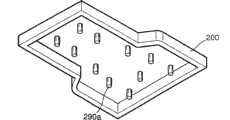
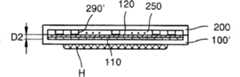
参照图5,本发明一个实施例的平板传热装置包括第一下板100、隔板110和毛细板120以及第一上板200,其中第一下板100的底部和诸如高发热芯片的热源(H)相接触,隔板110和毛细板120依次叠放在第一下板100上,而第一上板200罩着两个板110和120。Referring to Fig. 5, the flat plate heat transfer device of one embodiment of the present invention comprises the first
在制造平板传热装置期间,第一上板200和第一下板100沿着它们的边缘彼此结合,这样它们可以例如使用焊接、静电结合或热结合的方法被密封。具有非常小厚度的毛细板120包括多个平面吸液芯和多个形成在其间的孔。毛细板120可以至少包括两个不同的层。优选的是,在毛细板120上的毛细结构是规则和均匀的。但是,只要它们能把液相冷却剂从冷凝部P2传输到蒸发部P1,就可以采用任何毛细结构。优选的是,隔板110和毛细板120有同样的形状和尺寸。隔板110可以选择性地设置。因此,根据本发明的平板传热装置可以不包括隔板110。毛细板120和隔板110优选地形成为完全装配到第一上板200中,这样在第一上板200的内侧和毛细板120、隔板110的整体圆周之间就没有间隙。结果,即使由于物理碰撞而导致的震动,也能阻止毛细板120和隔板110移动而不整齐。优选地,第一上板200和第一下板100当从上方看时具有相同的形状。另外,优选的是,第一上板200的内部形状和尺寸在底侧与毛细板120和隔板110的形状和尺寸相同。During manufacture of the flat plate heat transfer device, the first
图5中所示的平板传热装置的厚度大约是几个毫米,例如1mm~2mm。必须具有一个空间,冷却热源(H)时产生的蒸气可穿过该空间进入到毛细板120和第一上板200之间的冷凝部P2。由于第一下板100通常比毛细板120和隔板110厚,毛细板120和隔板110的厚度仅占平板传热装置厚度的很小的百分比。换言之,毛细板120和隔板110非常薄。隔板110和毛细板120借助于液相冷却剂的表面张力保持粘附在第一下板100上,液相冷却剂例如为蒸馏水、乙醇、甲醇或丙酮。形成在隔板110隔片形成区110b中的隔片之间的距离大于形成在毛细板120的平面吸液芯形成区120b的平面吸液芯之间的距离。换言之,形成在隔片形成区110b中的隔片的密度远低于形成在平面吸液芯形成区120b中的平面吸液芯的密度。隔片形成区110b包括隔片和形成在其间的孔,通过这些孔,下板100暴露出来。平面吸液芯形成区120b包括平面吸液芯和形成在其间的孔,通过这些孔,第一下板100暴露出来。因此,隔片的密度远小于平面吸液芯的密度的事实意味着,形成在隔片之间孔的尺寸远大于形成在平面吸液芯之间孔的尺寸。在隔片形成区110b和平面吸液芯形成区120b分别形成的隔片和平面吸液芯的排列形式,分别由这两个区中孔的排列方式确定。换言之,如果隔片形成区110b中孔的形状和排列确定了,隔片的形状和排列就自动确定了。同样地,如果平面吸液芯形成区120b中孔的排列和形状确定了,平面吸液芯的排列和形状就自动确定了。因此,通过改变形成在隔片形成区110b和平面吸液芯形成区120b中的孔的尺寸、形状和排列,能在同一形成区110b和平面吸液芯形成区120b中分别形成不同尺寸、形状和排列的隔片和平面吸液芯,这将在后面做更充分地描述。The thickness of the flat heat transfer device shown in FIG. 5 is about several millimeters, for example, 1mm˜2mm. It is necessary to have a space through which vapor generated while cooling the heat source (H) can enter the condensation part P2 between the
如上所述,当形成在隔片形成区110b中的隔片密度远低于形成在平面吸液芯形成区120b中的平面吸液芯密度时,在隔片形成区110b中的孔区域足以包括形成在平面吸液芯形成区120b中的平面吸液芯和孔。即使隔板110位于毛细板120和第一下板100之间,毛细板的大部分底面也直接对着第一下板100。因此,毛细板120和第一下板100之间存在着足够的表面张力,从而使毛细板120和第一下板110保持贴附在一起。隔板110优选的是足够薄以产生甚至更大的毛细作用力。As described above, when the spacer density formed in the
即使假设毛细板120、隔板110和第一下板100的联接被液相冷却剂的表面张力紧紧保持在一起,由于物理冲击或无法预料的某些原因会导致液相冷却剂表面张力减弱,毛细板120也可能非所愿地从第一下板100分开。换言之,毛细板120和隔板110可能向着第一上板200移动。在这种情况下,液相冷却剂的循环可能被阻塞,阻止液相冷却剂有效地把热源(H)产生的热量带走。因此,冷却剂干涸现象可能发生,其中冷却剂停止供应到对应于与热源(H)接触的区H’的第一下板100的顶面上。如果干涸发生在蒸发部P1,则热源(H)的温度持续上升。如果这种现象发生,热源(H),即高发热芯片可能运转缓慢或不运转。一种更坏的情形是,安装高发热芯片的电子装置可能彻底停止运转。Even assuming that the connection of the
为了阻止毛细板120在第一下板100和第一上板200之间由于任何原因而自由移动,设置了各种固定件。图5中的附图标记290代表这种固定件的一个例子,该固定件为突起形状,其从第一上板200内表面凸向毛细板120,固定件290将在后面做更充分地描述。In order to prevent the
参照图5,由虚线标出的第一下板100上的一个区域130指的是和隔板110接触的区域。位于区域130外侧的第一下板110的边缘200a与第一上板200的边缘密封结合。优选的是,第一下板100的边缘200a具有1.5到3.0mm的宽度W0。与第一下板100的热源(H)相接触的蒸发部P1的区域小于不与热源(H)相接触的冷凝部P2的宽度,并且该区域是蒸发部P1产生的蒸气通过相变冷凝的地方。换言之,第一下板100的宽度在蒸发部P1中是常数。但是,该宽度从蒸发部P1和冷凝部P2之间的边界开始变宽了。于是,第一下板100在冷凝部P2中的宽度保持更宽的值。液相冷却剂在第一下板100顶面的特定区域蒸发,这个区域正好在第一下板100底部上的区域H’上方,该区域H’直接和热源(H)相接触。在该区域产生的蒸气通过位于第一上板200和毛细板120之间的空间移动到冷凝部P2。在冷凝部P2中,这些蒸气把热源(H)产生的热传递到外部,并变成液相冷却剂。通过这个过程,液相冷却剂在冷凝部P2中聚集起来。液相冷却剂一抵达冷凝部P2,它就渗透过对应于冷凝部P2的毛细板120的平面吸液芯形成区120b。于是液相冷却剂借助于毛细作用力穿过形成在平面吸液芯形成区120b中的平面吸液芯和第一下板100之间的空间从冷凝部P2到达蒸发部P1。Referring to FIG. 5 , an
隔板110位于毛细板120和第一下板100之间。但是,即使没有隔板110,毛细板120和第一下板100也彼此非常靠近,这样,在第一下板100与毛细板120之间,特别是与形成在平面吸液芯形成区120b中的平面吸液芯之间的间隙足够小,以产生毛细作用力。在图26中,穿过平面吸液芯中的间隙或穿过第一下板100与平面吸液芯140、142和144之间的间隙,聚集在冷凝部P2的液相冷却剂流进蒸发部P1中。毛细板120包括边缘120a,该边缘与第一上板200的内周和边缘120a内的平面吸液芯形成区120b相接触。如图6到8所示,在平面吸液芯形成区120b中,形成各种平面吸液芯。这些平面吸液芯和第一下板100形成多个细槽,冷却剂穿过该细槽流动。隔板110包括边缘110a,该边缘与第一下板100及第一上板200的内周和边缘110a内的隔片形成区110b相接触。The
另一方面,在第一下板100和第一上板200之间必须形成一个空腔。如图10-20所示,该空腔包括蒸气移动空间250和安装有毛细板120或毛细板120及隔板110的空间。因此,考虑到该事实,制造第一上板200是可能的。On the other hand, a cavity must be formed between the first
参照附图6-8,下面更充分描述毛细板120和形成在平面吸液芯形成区120b中的平面吸液芯的平面形状。The planar shape of the
图6示出这样的例子,其中形成在蒸发部P1的平面吸液芯是直线形,图7中示出的是其中平面吸液芯是网筛形的例子,而图8中示出的是其中平面吸液芯是放射型的例子。Fig. 6 shows an example in which the planar liquid wick formed in the evaporation part P1 is linear, Fig. 7 shows an example in which the planar liquid wick is mesh-shaped, and Fig. 8 shows a Among them, the planar liquid wick is an example of the radial type.
参照图6,第一至第三平面吸液芯140、142和144形成在毛细板120的蒸发部P1中。第二平面吸液芯142和围绕着蒸发部P1在边缘120a下的水平部分相接触,并沿着该水平部分延伸到冷凝部P2。和第二平面吸液芯142对称的第三平面吸液芯144与毛细板边缘120a上部的水平部分接触,并沿其延伸到冷凝部P2。如图6所示,第二和第三平面吸液芯142和144有这样的形式,即边缘120a的上、下部分在边缘120a的内侧方向延伸。和蒸发部P1相比,毛细板120在冷凝部P2中的尺寸变得更宽。因此,第二和第三平面吸液芯142和144在冷凝部P2开始的地方扩大范围。Referring to FIG. 6 , first to third
特别地,第二平面吸液芯142在冷凝部P2中被分成多个平面吸液芯。在这些分开的平面吸液芯中,一个作为母体的平面吸液芯实际上成直线地横过冷凝部P2与毛细板120的边缘相连。分开的平面吸液芯的剩余部分,即第四平面吸液芯142a和第五平面吸液芯142c形成在冷凝部P2的延伸区域中。第四平面毛细板142a被弯曲成和毛细板120的边缘的围绕冷凝部P2的部分的形状相同。第四平面吸液芯142a和围绕着冷凝部P2的毛细板120a的右边缘连接。第五平面吸液芯142c形成在第四平面吸液芯142a和作为第四和第五吸液芯142a和142c的母体的一个平面吸液芯之间,并和毛细板120的右边缘连接。第五平面吸液芯142c形成直线型,并和第二平面吸液芯142平行。In particular, the second
以和第二平面吸液芯142同样的方式,第三平面吸液芯144在冷凝部P2开始处被分成多个第六和第七平面吸液芯144a和144c。第六和第七平面吸液芯144a和144c形成在冷凝部的延伸区域中。如第二平面吸液芯142那样,在多个从第三平面吸液芯144分出的多个平面吸液芯中作为母体的一个平面吸液芯,实际上直线地穿过冷凝部P2,和毛细板120的边缘连接。第六和第七平面吸液芯144a和144c与第四和第五平面吸液芯142a和142c对称,因此,省略了它们的详细说明。In the same manner as the second
具有预定宽度的第二孔142b形成在第四平面吸液芯142a之间,并且具有预定宽度的第三孔142d形成在第五平面吸液芯142c之间。第四孔144b和第五孔144d分别形成在第六平面吸液芯144a之间和第七平吸液芯144c之间。这样,毛细板120包括多个平面吸液芯和多个形成在平面吸液芯之间的孔。Second holes 142b having a predetermined width are formed between the fourth
聚集在冷凝部P2中的液相冷却剂穿过第二到第五孔142b、142d、144b和144d流进在第一下板100与第四到第七平面吸液芯142a、142c、144a和144c之间毛细作用力发生作用的空间中,并流到与第二平面吸液芯142相应的蒸发部P1中。液相冷却剂也可以经第二至第五孔142b、142d、144b和144d流动到蒸发部P1。The liquid-phase coolant accumulated in the condensation part P2 flows into the first
如图6中所示,从第二到第七平面吸液芯142、144、142a、142c、144a和144c中选择的至少一些平面吸液芯可以通过平面吸液芯桥接260a相连,从而稳定地把毛细板120贴附在第一下板100上,此时平面吸液芯桥接260a连接两个相邻的平面吸液芯。由于平面吸液芯桥接260a连接相邻平面吸液芯的侧面,这样,平面吸液芯桥接260a和第一下板100之间就可能有这样的毛细作用力发生,该作用力与第一下板100和第四至第七平面吸液芯142a、142c、144a和144c之间毛细作用力同样大。因此,即使液相冷却剂在穿过第二至第五孔142b、142d、144b和144d流向蒸发部P1的路径上遇到平面液芯桥接260a,它的蒸气也能继续穿过平面吸液芯桥接260a和第一下板100之间的空间。As shown in FIG. 6, at least some planar wicks selected from the second to seventh
多个第一平面吸液芯140形成在平面吸液芯形成区120b的剩余区域内,其中第二到第七平面吸液芯142、144、142a、142c、144a和144c不在该剩余区域内形成。第一孔150形成在第一平面吸液芯140之间。换言之,除了平面吸液芯形成区120b中冷凝部P2的延伸区域外的剩余区域中,形成有第一平面吸液芯140。第一平面吸液芯140从边缘120a的围绕蒸发部P1的垂直部分开始,该第一平面吸液芯140与第二及第三吸液芯142和144平行,并以实际成直线穿过蒸发部P2,和边缘120a连接。具有预定宽度的第一孔150形成在第一平面吸液芯140和第二及第三吸液芯142、144的每一个之间。第一孔150也形成在第一平面吸液芯140之间。第一孔150和第一平面吸液芯140一起穿过蒸发部P1和冷凝部P2延伸至毛细板120的边缘120a。因此,如形成在冷凝部P2延伸区域中的第二至第五孔142b、142d、144b和144d中一样的情况,液相冷却剂可以通过毛细作用力穿过第一孔150,在第一吸液芯140和第一下板100之间流动。和第二至第五孔142b、142d、144b和144d不同,第一孔150直接从冷凝部P2延伸至蒸发部P1。而且,由于第一孔150的宽度非常窄,这样毛细作用力可以产生。因此,液相冷却剂通过第一孔150本身也可以穿过第一吸液芯140和第一下板100之间的空间移动到蒸发部P1。在蒸发部P1产生的蒸气通过第一孔150排放到蒸气通路250,并且因此蒸气在蒸发部P2的实际蒸发区域就由第一孔150确定。A plurality of first
如图7所示,和上述平面吸液芯不同的第八平面吸液芯160a位于毛细板120的平面吸液芯形成区160内。多个第六孔160b和多个第七孔160c形成在第八平面吸液芯160a中。第六孔160b形成在蒸发部P1中,该孔并且是蒸气从该处放出的蒸发区域。另一方面,形成在冷凝部P2中的第七孔160c是液相冷却剂流入冷凝部P2的入口。优选的是,第六和第七孔160b和160c具有相同尺寸。然而,第六和第七孔160b和160c也可具有不同尺寸。第六和第七孔160b和160c彼此以预定距离分开布置。因此,第八平面吸液芯160a看起来象网筛。As shown in FIG. 7 , an eighth
如图8所示,和上述平面吸液芯不同的平面吸液芯形成在毛细板120的平面吸液芯形成区170中。在图8中,和图6和7不同,为了方便绘图,平面吸液芯用直线代表。As shown in FIG. 8 , a planar wick different from the above-described planar wick is formed in the planar
参照图8,形成在平面吸液芯形成区170中的平面吸液芯,可以根据它们所属的区域,即根据是蒸发部P1还是冷凝部P2而在形状上有所不同。Referring to FIG. 8, the planar wicks formed in the planar
特别地,形成在蒸发部P1中的第九平面吸液芯170a成放射状从蒸发部P1的中心区(C)开始延伸。第十和第十一平面吸液芯170C和170D形成在冷凝部P2中。第九平面吸液芯170a包括多种放射状平面吸液芯。换言之,第九平面吸液芯170a被分成四个放射状平面吸液芯:形成第一放射状平面吸液芯,从而在中心区C的中心相遇。第二放射状平面吸液芯形成在一放射状平面吸液芯之间,从中心区(C)的边界开始延伸。第三放射状平面吸液芯形成在第二平面吸液芯和第一平面吸液芯之间,从距离中心区(C)边界一定距离的预定点开始延伸。第四放射状平面吸液芯形成在第一和第三放射状平面吸液芯之间,或在第二和第三放射状平面吸液芯之间,并从比第三放射状平面吸液芯开始的预定点更远的特定点开始延伸。第八孔170b形成在第一到第四放射状平面吸液芯之间。蒸气从第八孔170b放出。第八孔170b延伸到冷凝部P2。In particular, the ninth
第十和第十一平面吸液芯170c和170d从第九平面吸液芯170a延伸出,并在冷凝部P2开始的部分变为直线型。第十一平面吸液芯170d在冷凝部P2起点处被分成多个第十二平面吸液芯170d1、170d2、...、170dn和多个第十三平面吸液芯170e。第十平面吸液芯170c形成在冷凝部P2中,并和形成在冷凝部P2的第一平面吸液芯140相同,并且第十一到第十三平面吸液芯170d、170d1、...、170dn和170e实际上和在冷凝部P2中形成的第二或第三平面吸液芯142、144相同。The tenth and eleventh
第一到第四放射状平面吸液芯中的一些,或在冷凝部P2中成直线型的上述平面吸液芯中的一些由平面吸液芯桥接260a连接。Some of the first to fourth radial planar wicks, or some of the above-mentioned planar wicks in a straight line in the condenser part P2 are connected by
如图6-8所示,各种平面吸液芯可以形成在毛细板120的平面吸液芯形成区120b中。除了在图6-8所示的实施例外,具有其它形状的平面吸液芯可以形成在平面吸液芯形成区120b中。例如,多个孔可以形成在平面吸液芯形成区120b中,这样,液相冷却剂可以从冷凝部P2流到蒸发部P1,即,由此聚集在冷凝部P2的液相冷却剂通过平面吸液芯之间的空间和/或通过第一下板100和平面吸液芯之间的空间,顺利流进蒸发部P1。在这种情况下,多个孔可以在蒸发部P1和冷凝部P2的所有区域中被排列成网筛形状,或根据这些孔所在区域的特性成任意形状。孔的尺寸也可以改变。Various planar wicks may be formed in the planar
参照附图9A,多个第一隔片180a和多个第二隔片180b水平排列在隔片形成区110b中。第一隔片180a穿过蒸发部P1和冷凝部P2形成。第二隔片180b在冷凝部P2的延伸区域中被排列成和第一隔片180a平行。隔板桥接190用于连接第一和第二隔片180a和180b中的一些。隔板桥接190是一种示例的部件,其用于稳定隔板110的姿态。隔板桥接190位于第一和第二隔片180a、180b之间及第一隔片180a之间。优选的是,隔板桥接190排列成彼此平行的行。但是,它们可以被排列成锯齿形。Referring to FIG. 9A, a plurality of
第一隔片180a水平穿过蒸发部P1和冷凝部P2,并彼此分开一个第一距离S1。第一距离S1比形成在平面吸液芯形成区120b中的平面吸液芯之间的间隙稍宽。第二隔片180b中的一些形成在横穿蒸发部P1的方向上,其它形成在横穿冷凝部P2的方向上。第二隔片180彼此平行,并隔开一个第二距离S2。第二距离S2比第一距离S1稍宽。同时,第一、第二距离S1、S2比平面吸液芯之间的间隙更宽,每个第一隔片180a的宽度几乎和每个平面吸液芯的宽度相等。The
隔板110可以形成不同的形状。例如,隔板110的形状和/或尺寸可以与毛细板120的形状和或尺寸不同,特别地,隔板110可以替换为形成在毛细板120中与平面吸液芯平行的一些隔片或单独材料。隔片可以和隔板110分开,或永久固定在第一下板100上。The
参照图9B,隔板桥接190位于两个相邻第一隔片180a之间,以及位于边缘110a和第一隔片180a之间,这样,它们就可以连接两个相邻的第一隔片180a,并在每个第一隔片180a的任一侧上部能把第一隔片180a和边缘110连接起来。该事实也用到形成在冷凝部P1中的隔板桥接190。Referring to FIG. 9B, the
接下来,参照附图10-25描述各种平板传热装置的例子,其中毛细板120和隔板110依次叠加在第一下板100上。将参照附图26-30描述其中不具有隔板110的各种平板传热装置的例子。图6中所示的毛细板和图9B中所示的隔板110在前者中被使用。在后者,图6中所示的毛细板120被使用。Next, various examples of flat heat transfer devices will be described with reference to FIGS. 10-25 , in which
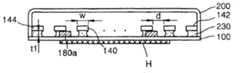
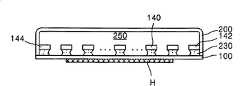
参照图10,当隔板110的第一隔片180a稀疏地形成在第一下板100上时,第一到第三平面吸液芯140、142和144则稠密地形成在第一下板100上。如图10所示,形成在平面吸液芯形成区120b中的平面吸液芯的密度比形成在隔片形成区110b上的隔片密度大得多。这种密度分布保持到冷凝部P2中。因此,液相冷却剂穿过第一到第三平面吸液芯140、142和144从冷凝部P2流到蒸发部P1。从冷凝部P2流到蒸发部P1的液相冷却剂的传输由毛细作用产生。因此,优选的是,第一下板100和第一到第三平面吸液芯140、142及144之间保持一条间隙,这样,液相冷却剂的毛细作用就可以产生。第一隔片180a支撑着第一到第三平面吸液芯140、142和144,因此,第一下板和第一到第三平面吸液芯140、142和144之间的间隙由第一隔片180a的厚度确定。因此,优选的是,第一隔片180a的厚度t1足够小,以对液相冷却剂产生毛细作用,使该液相冷却剂从冷凝部P2流进第一下板100和第一到第三平面吸液芯140、142和144之间。例如,第一隔片180a的厚度t1优选是50μm。附图标记230指的是这样的液相冷却剂,该冷却剂通过毛细作用,穿过第一下板100和第一到第三平面吸液芯140、142和144之间的间隙,从冷凝部P2流到蒸发部P1。附图标记d代表第一和第二吸液芯140和142之间的距离、第一和第三吸液芯140和144之间的距离或第一吸液芯140之间的距离。冷却剂在蒸发部P1蒸发的区域由距离d确定,优选的是,该距离d是一个可以降低蒸发热阻的预定值,该距离例如为100μm。附图标记w代表第一到第三平面吸液芯140、142和144的宽度。优选的是,第一到第三平面吸液芯140、142和144的宽度w根据蒸发部P1中的冷却剂蒸发区和蒸发热阻来确定。例如,第一到第三平面吸液芯140、142和144的宽度是100μm。Referring to FIG. 10 , when the
在图10中,优选的是,第一到第三平面吸液芯140、142和144的厚度比第一隔片180a的厚度大。例如,第一到第三平面吸液芯140、142和144的厚度是100μm。优选的是,第一下板100的顶面和第二上板200的内表面之间的距离根据第一隔片180a的优选厚度、第一到第三平面吸液芯140、142和144的优选厚度及位于毛细板120和第一上板200之间的蒸气移动空间来确定。例如,第一下板100的顶面和第一上板200的内表面之间的距离可以是0.8mm。如图10所示,鉴于第一下板100和第一上板200的厚度优选的是0.5mm,则平板换热器的整个厚度优选的是1.8mm。该装置的整个厚度可能随组成第一下板100和/或第一上板200的材料,或随组成毛细板120和隔板110的材料的不同而不同。在图11A中,第一和第二平面吸液芯140、142及第一隔片180a是三维示出的。In FIG. 10, it is preferable that the thickness of the first to third planar liquid-
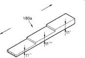
如图11A所示,第一隔片180a的部分可以有不同的厚度。在这种情况中,由于液相冷却剂需要很快地从冷凝端P2供应到蒸发部P1,如图11B所示,优选的是,第一隔片180a具有渐减的厚度,这样第一隔片180a在冷凝部P2的厚度大于其在蒸发部P1的厚度。优选的是,第一隔片180a在冷凝部P2的厚度t1’等于或小于最大厚度,该最大厚度是能使第一到第三毛细结构140、142和144给在冷凝部P2中的液相冷却剂施加毛细作用力的最大厚度。优选的是,蒸发部P1中第一隔片180a的厚度t1”小于冷凝部P2中的第一隔片180a厚度。As shown in FIG. 11A, portions of the
作为替换,如图11c所示,第一隔片180a可以具有不规则变化的厚度t1。换言之,在冷凝部P2的隔片180a具有厚度t1’,在蒸发部P1具有厚度t1”,在冷凝部P2和蒸发部P1之间的一些地方具有厚度t1”’。在这里,厚度t1”’小于厚度t1’,但是大于厚度t1”。Alternatively, as shown in FIG. 11c, the
如图11C所示,如果隔片180形成阶梯状,则安装在第一隔片180a上的毛细板120优选地也形成阶梯状。As shown in FIG. 11C, if the spacer 180 is formed in a stepped shape, the
如上所述,第一隔片180a在冷凝部P2具有比蒸发部P1更大的厚度,毛细作用力在在蒸发部P1比在冷凝部P2变得更强,这样,液相液相冷却剂可以更迅速地从冷凝部P2传输到蒸发部P1。As described above, the
图12示出液相冷却剂的蒸发,该冷却剂吸收来自热源H的热量,穿过第一到第三平面吸液芯140、142和144之间的孔。在图12中,附图标记230a代表蒸气。在蒸发部P1产生的蒸气230a穿过位于第一上板200和第一到第三平面吸液芯140、142和144之间的蒸气移动空间250,转移到冷凝部P2。FIG. 12 shows the evaporation of the liquid-phase coolant, which absorbs heat from the heat source H, passing through the holes between the first to third
图13A到13D示出了这样一种方式,其中该方式阻止第一到第三平面吸液芯140、142和144由于外部冲击或其它原因在垂直于第一下板100的方向上移动。在这些附图中,第一到第三平面吸液芯中的至少一些通过平面吸液芯桥接260a彼此连接。优选的是,平面吸液芯桥接260a的厚度比第一到第三平面吸液芯140、142和144的厚度薄。但是,如图13B所示,平面吸液芯桥接260a的厚度可以和第一到第三平面吸液芯140、142和144的厚度相同。如图13A所示,在平面吸液芯桥接260a的厚度比第一到第三平面吸液芯140、142和144厚度薄的情形中,优选的是,该平面吸液芯桥接和第一到第三平面吸液芯140、142和144的任一侧的上部连接。作为替换,如图13C所示,平面吸液芯桥接260a可以用于连接第一到第三平面吸液芯140、142和144的任一侧的中部。如图13D所示,平面吸液芯桥接260a可以用于连接第一到第三平面吸液芯140、142和144的任一侧的下部。在上述任一种情形中,与第一下板100和第一到第三平面吸液芯140、142和144之间存在的毛细作用力相同的毛细作用力存在于平面吸液芯桥接260a和第一下板100之间。因此,液相冷却剂在其从冷凝部P2到蒸发部P1的流路上遇到平面吸液芯桥接260a,液相冷却剂可以穿过第一下板100和平面吸液芯桥接260a之间的间隙在同一方向继续流动。另外,由于平面吸液芯桥接260a的数量远小于平面吸液芯的数量,平面吸液芯桥接260a不会显著影响液相冷却剂的流动。13A to 13D show a manner in which the first to third
图14示出通过平面吸液芯桥接260a连接的第一到第三平面吸液芯140、142和144的三维结构。参照图14,每个平面吸液芯桥接260a连接两个相邻平面吸液芯的部分。为了增加毛细板120所在位置的稳定性,优选的是毛细板桥接260a被排列成锯齿状而不是排成行。优选的是,蒸发部P1中平面吸液芯桥接260a的数量应考虑蒸发区和蒸发热阻进行限定。Figure 14 shows the three-dimensional structure of the first to third
图15示出一种平板传热装置,该装置包括一种阻止第一到第三平面吸液芯140、142和144在垂直于第一下板100的方向上移动的结构。图15中所示的平板传热装置包括一个弹性元件280,例如片簧,该元件位于第一上板200和第三平面吸液芯140、142和144之间。该弹性元件280可以吸收施加给平板传热装置的外部冲击,这样可以防止第一到第三平面吸液芯140、142和144在垂直于第一下板100的方向上运动。在图16中,弹性元件280和第一到第三平面吸液芯140、142和144是三维显示的。参照图16,弹性元件280具有比第一到第三平面吸液芯140、142和144长度小的宽度。并且,弹性元件280不占位于第一上板200和第一到第三平面吸液芯140、142和144之间的蒸气移动空间250中的大量空间。因此,可以忽略弹性元件280对蒸气从蒸发部P1到冷凝部P2运动的影响。FIG. 15 shows a flat plate heat transfer device including a structure for preventing the movement of the first to third
图17示出一种平板传热装置,该传热装置包括一种用于阻止第一到第三平面吸液芯140、142和144在垂直于第一下板100方向上移动的部件,该部件例如为弹性元件280和平面吸液芯桥接260a。Fig. 17 shows a flat heat transfer device, which includes a component for preventing the first to
图18A示出一种平板传热装置,该传热装置包括凸向第一到第三平面吸液芯140、142和144的第一突起290,作为图17所示的部件。如图18B所示,该第一突起290稀疏地形成,象第一隔片180a一样具有低密度。如图18A所示,优选的是,第一突起290具有矩形截面,并沿着第一上板200的长度方向延伸。但是,分别如图18C和18D所示,第一突起290可以具有圆形或多边形截面。FIG. 18A shows a flat plate heat transfer device including a
第一突起290突出得非常接近第一到第三平面吸液芯140、142和144的表面,这样,它们几乎可以接触第一到第三平面吸液芯140、142和144。在类似这种情况的状态,如图19所示,平面桥接260a可以进一步位于第一到第三平面吸液芯140、142和144之间。The
图20示出一种平板传热装置,该传热装置包括位于第一下板100上的第十四平面吸液芯300,该第十四平面吸液芯300是一个由毛细板120和隔板组成的整体作为图17中所示的部件。每个第十四平面吸液芯300包括一个载体300b和翼300a,该载体具有和第一隔片180a相同的厚度和功能,该翼象第一到第三平面吸液芯140、142和144一样,使液相冷却剂230从冷凝部P2流向蒸发部P1。每个第十四平面吸液芯300可以具有载体300b,或者作为替换的实施例,第十四平面吸液芯300中只有一些具有载体300b。在图21中,第十四平面吸液芯300以三维显示。Fig. 20 shows a flat heat transfer device, which includes a fourteenth
上述形成在毛细板120的平面吸液芯形成区120b中所有的平面吸液芯和/或孔,和第十四平面吸液芯300一起用干蚀或湿蚀或冲压的手段形成。因此,本发明实施例所述的平面吸液芯和孔是容易制造的。另外,平面吸液芯的和孔的制造成本也可以降低。并且,根据蒸发部P1和冷凝部P2的特征来形成平面吸液芯、隔片和平面吸液芯桥接是可能的。All the planar wicks and/or holes formed in the planar
图22所示的情形是突起290作为图17所示的部件,位于第一上板200的内表面处,其结果如图20所示的情况。图23表示这样一种情形,其中平面桥接260a形成在第十四平面吸液芯300之间,作为图17所示的部件。图24表示这样一种情形,其中,弹性元件280形成在第一上板200和第十四平面吸液芯300之间,作为图17所示的部件。The situation shown in FIG. 22 is that the
图25表示这样一种情形,其中,作为图17中所示部件的弹性元件280和平面吸液芯桥接260a位于平板传热元件中,该传热装置包括第十四平面吸液芯300。FIG. 25 shows a situation in which the
不包括隔板的平板传热装置及其变化将参照附图26-30在下文中描述。A flat plate heat transfer device that does not include baffles and variations thereof will be described hereinafter with reference to Figures 26-30.
参照图26,只有第一到第三平面吸液芯140、142和144位于第一下板100和第一上板200之间,其中这些吸液芯140、142和144构成了由图1中所示毛细板120的平面吸液芯形成区120b。第一到第三平面吸液芯140、142和144被排列成和第一下板100非常接近。第一到第三平面吸液芯140、142和144和第一下板100通过其间存在的液相冷却剂230的表面张力粘在一起。液相冷却剂230在冷凝部P2中第一下板100和第一到第三平面吸液芯140、142和144之间流动,并借助于第一下板100和第一到第三平面吸液芯140、142和144之间通过它们的贴附产生的毛细作用力而从蒸发部P1移动到冷凝部P2。Referring to FIG. 26, only the first to third planar liquid-
即使毛细板120和第一下板100之间没有隔板110,液相冷却剂230也可以在第一下板100和毛细板120之间流动。液相冷却剂230于是借助于毛细作用力穿过第一下板100与第一到第三平面吸液芯140、142和144之间的间隙,从冷凝部P2移动到蒸发部P1,并被热源(H)产生的热量蒸发。该过程中产生的蒸气穿过形成在第一到第三平面吸液芯140、142和144之间的孔,在形成在第一上板200和第一到第三平面吸液芯140、142和144之间、延伸到冷凝部P2的蒸气移动空间250放出。于是,蒸气经过蒸气移动空间250移动到冷凝部P2。Even without the
图27表示一种情况,其中第一突起290位于第一上板内表面,以面向图26所示平板传热装置的第一到第三平面吸液芯140、142和144。第一突起290突向第一到第三平吸液芯140、142和144。第一突起装置290是一种辅助装置,用于把毛细板120紧密地固定在第一下板100上,并阻止由于外部冲击或其它原因导致的第一下板100和第一到第三平面吸液芯140、142和144之间距离增加,超出液相冷却剂230的表面张力起作用的范围。第一突起290也阻止第一上下板200和100在冷却热源H的过程中被弯曲或扭曲。FIG. 27 shows a case where the
图28表示一种情形,其中平面吸液芯桥接260a位于图26中所示的平板传热装置中的第一到第三平面吸液芯140、142和144之间。参照图13A-13D已经作过描述的平面吸液芯桥接260在这里就不再描述。另一方面,图27所示的第一突起290也可以与图28所示平板传热装置中的平面吸液芯桥接260a一起设置。FIG. 28 shows a situation where the
图29示出了这样的情况,其中弹性元件280设置在图26所示的最终的蒸气移动空间250中,该弹性元件作为一种把毛细板120固定到第一下板100上的辅助装置。例如,弹性元件280可以是上面已经提及过的片簧。另一方面,图28中所示的平面吸液芯桥接260a也可以和弹性元件280一起设置在第一到第三平面吸液芯140、142和144之间。FIG. 29 shows a case where an
如平面吸液芯桥接260a、弹性元件280和在第一上板200内表面的第一突起290的用于固定毛细板120的辅助部件,可以是单独的材料或用金属蚀刻的方式形成。并且,第一上板200和辅助部件可以使用压制加工制成一体。The auxiliary parts for fixing the
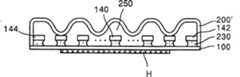
图30表示这样一个例子。如图30所示,第二上板200’面对毛细板120的表面是不平的。第二上板200’接触第一到第三平面吸液芯140、142和144的突起部分可以作为固定毛细板120的辅助部件。第二上板200’的不平部分从冷凝部P1到蒸发部P1形成。因此,突起部分之间的凹部用做蒸气移动到冷凝部P2的通道,其中凹部不和第一到第三平面吸液芯140、142和144接触。Fig. 30 shows such an example. As shown in FIG. 30, the surface of the second upper plate 200' facing the
如图30所示,第一上板200面对毛细板120的不平表面可以是波浪形的,也可以是未示出的方形锯齿形。As shown in FIG. 30 , the uneven surface of the first
例如,用于把蒸发部P1供应的蒸气冷凝成液体的散热装置可以是风扇,根据本发明实施例,该风扇位于平板传热装置冷凝部P2的外侧。图31A到33A和33B示出了根据本发明的散热装置和平板传热装置的位置关系。在图31A到33A和33B中,平板传热装置没有使用用于固定毛细板120的辅助部件。但是,也可以使用包括用于固定毛细板120的辅助部件的平板散热装置。为了便于绘图,第一到第三平面吸液芯140、142和144在图31A到33A和33B没有明确表示。For example, the cooling device for condensing the vapor supplied by the evaporating part P1 into a liquid may be a fan, and according to an embodiment of the present invention, the fan is located outside the condensing part P2 of the flat heat transfer device. 31A to 33A and 33B show the positional relationship of the heat dissipation device and the flat heat transfer device according to the present invention. In FIGS. 31A to 33A and 33B , the flat plate heat transfer device does not use auxiliary parts for fixing the
图31示出了安装在对应于冷凝部P2第一上板200的预定区域上的散热装置400。FIG. 31 shows the
图32示出了和热源(H)一起放在第一下板100底面上的散热装置400。在图32中,散热装置400被放在第一下板100对应于冷凝部P2的底面上。散热装置400被放在其上的第一下板100的部分可以比第一下板100的剩余部分薄。FIG. 32 shows the
图33A-33B所示的平板传热装置和图31中所示的平板传热装置的颠倒过来的图是相同的。在图33A和33B中,第一下板100位于平板传热装置的上部,作为上板,在下部的第一上板200作为下板,并且热源(H)是个发热芯片,被贴附在平板传热装置的顶面。图33A和33B代表了一种情况,其中图31所示的平板传热装置被颠倒过来。因此,热源(H)位于第一下板100对应于蒸发部P1的预定部分,该第一下板被用做上板。如图33A所示,散热装置400可以被放在第一上板200对应于冷凝部P2的预定部分,该上板被用作下板。如图33B所示,作为替换,散热装置400和热源(H)一起可以位于第一下板100上,在该种情况下,毛细板120几乎是从第一下板100悬挂下来,因此在向下方向受重力影响。即使毛细板120可以借助于毛细板120和第一下板100之间存在的液相冷却剂的表面张力,保持贴附在第一下板100上,和本发明前面的实施例相比,毛细板120和第一下板的贴附状态也会不稳定得多。因此,优选的是,在蒸气移动通道250中提供把毛细板120固定到第一下板100上的辅助部件。另外,为了使液相冷却剂流动顺畅,毛细板120可以延伸到第一上板200对应于散热装置400的预定部分,其中该第一上板200用作下板。The flat plate heat transfer device shown in Figures 33A-33B is the same as the inverted view of the flat plate heat transfer device shown in Figure 31. In FIGS. 33A and 33B, the first
在图31到图33A和33B所示的平板传热装置中,多个可以任意控制、尺寸更小的散热装置可以代替散热装置400。在制造平板传热装置的最后步骤中,液相冷却剂被注入平板传热装置。为了把液相冷却剂注入平板传热装置,一个具有任意形状的填充端口,例如,具有圆管形状的填充端口位于第一上板200或第一下板100上,或二者均有填充端口。图34示出了包含填充端口的平板传热装置。如图34所示,第一上板200的任一端都有填充端口。换言之,填充端口450a围绕着蒸发部P2被安装在第一上板200侧壁上,第二填充端口450b安装在蒸发部P1中的第一上板200的另一端。In the flat heat transfer device shown in FIG. 31 to FIGS. 33A and 33B , multiple controllable heat sinks of smaller size can replace the
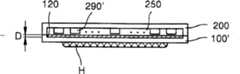
上面已经做过描述的第一下板100具有平的顶面和均匀的厚度。但是,如图35所示,可以有第二下板100’,在该第二下板中有一个区域130,毛细板120或隔板110被安装在该区130中,该区130具有比与上板200边缘接触的区域200a深的深度D。就第二下板100’而言,区域130的厚度比与上板200的边接触的区域200a薄。下文中,将描述包括第二下板100’的平板传热装置。在该平板传热装置中,只有毛细板120在第二下板100’和第一上板200之间。但是,平板传热装置可以进而包括与毛细板120一起的隔板110。The first
图36是包括第二下板100’的平板传热装置的剖面图。在这里,第二突起290’面对毛细板120形成在第一上板200的内表面上,作为固定毛细板120的部件。第二突起290’和第一突起290的功能是相同的,因此省略了它们的说明。优选的是,对应于冷凝部P2的散热装置400形成在第一上板200的预定区域。但是,如图37中的虚线所示,散热装置400也可以被附着在第二下板100’的底面。第一上板200和第二下板100’用各种联接方法联接在一起,如焊接、静电联接或热联接。该事实可以运用到下述的上板和下板的联接中。Fig. 36 is a cross-sectional view of a flat plate heat transfer device including a second lower plate 100'. Here, the second protrusion 290' is formed on the inner surface of the first
图37是包括第三下板100”和第三上板200”的平板传热装置的剖面图。在图37中,将要安装毛细板120的第三下板100”的特定区域130凹进一个第二深度D1,第三上板200”是具有均匀厚度的平板。D1大于D2。蒸气移动空间250由第三下板100”提供,该下板除了边缘以外的部分凹进第二深度D1。一个空隙,即蒸气移动空间250位于第三上板200”和毛细板120之间。和本发明前述的实施例不同,第三上板200”的厚度是均匀的,蒸气移动空间250由第三下板100”提供,该第三下板除了边缘以外,剩余部分凹进第二深度D1。第二突起290’形成在蒸气移动空间250中。图37中虚线表示对应于冷凝部P2的散热装置400,安装在第三上板200”的预定区域的该散热装置也可以被附着到第三下板100”的底面上。Fig. 37 is a cross-sectional view of a flat plate heat transfer device including a third
图38是沿着图36中38-38’线截取的平板传热装置的剖面图,图39是沿着图37中39-39’线截取的平板传热装置的剖面图。在图38和39中,可设置图28所示的平面吸液芯桥接260a或图29所示的弹性元件280,用于代替第二突起290’作为固定毛细板120的辅助部件。这个事实也可以应用于图40和图41。Figure 38 is a cross-sectional view of the flat-plate heat transfer device taken along line 38-38' in Figure 36, and Figure 39 is a cross-sectional view of the flat-plate heat transfer device taken along line 39-39' in Figure 37. In FIGS. 38 and 39, the
在图38和39中,隔板110可以还设置在毛细板120与第二或第三下板100’或100”任一板之间。图40表示一种情形,其中隔板100位于毛细板120和第二下板100’之间,图41的情形是,隔板110位于毛细板120和第三下板100”之间。在前者中,考虑到隔板110的厚度,第二下板除了边缘以外的剩余部分都凹进一个第三深度D2(D2>D)。在后者中,考虑到隔板110的厚度,第三下板100”除了边缘以外的剩余部分都凹进一个第四深度D3(D3>D1>D2)。In Figures 38 and 39, the
图40和41所示的隔板110可以具有与毛细板120不同的形状和尺寸。例如,隔板110可以形成包含多个孔的任意形状,在这种情况下,优选的是,孔的尺寸大于形成在毛细板120中孔的尺寸。The
隔板110可以被多个具有不影响液相冷却剂运动的简单结构的多个隔片所代替。The
毛细板120包括平面吸液芯和位于平面吸液芯之间的孔。平面吸液芯的形状和排列取决于孔的形状和排列。因此,液相冷却剂从冷凝部P2到蒸发部P1的运动方向也取决于所述孔。正如前面的本发明的每一个实施例,孔的排列方式根据液相冷却剂的运动方向来确定。
如图42和43所示,根据本发明实施例的平板传热装置还包括位于上板200内侧壁上的垂直隔片500。引进垂直隔片500来在上板200与位于由上板200和下板100围绕的空间中的元件、即毛细板120之间保持一条细间隙。As shown in FIGS. 42 and 43 , the flat plate heat transfer device according to the embodiment of the present invention further includes
如果上板200和下板100所限定的空间中的元件接触上板200的内表面,则用于密封上板200和下板100的粘接剂有可能沿着下板100的表面渗透过下板100和上板200之间的粘合体。因此,垂直隔片500位于上板200内侧壁中,因而确保了在上板200和元件之间的间隙。If components in the space defined by the
如图18所示,在根据本发明的传热装置中,第一隔片180a和下板100可以形成一体(下文中,指的是第一实施例)或位于上板200内表面的第一突起290和毛细板120可以形成一体(指的是第二实施例)。作为替换,预定的部件可以形成在下板100的表面处来扩大蒸发部P1中液相冷却剂和下板100的接触面积(指的是第三实施例)。作为替换,用于协助将液相冷却剂从冷凝部P2向蒸发部P1传输的辅助部件可以位于下板100的表面处,这样,液相冷却剂可以通过该辅助部件传输(指的是第四实施例)。作为替换,上下板200和100每个都由两个不同的元件组成(指的是第五实施例)。As shown in FIG. 18, in the heat transfer device according to the present invention, the
图44是根据本发明第一实施例的传热装置的剖面图。在图44中,附图标记510和510a分别代表与隔片一体形成一个主体的下板和设置在下板上的隔片突起。隔片突起510a和图10和12所示的第一隔片180的功能几乎相同,并具有与第一隔片180a的厚度相同的高度(h)。隔片突起510a在区和区中的高度可以不同,这与图11B和11C中所示的情形相似。例如,隔片突起510a在冷凝部P2的高度可以大于其在蒸发部P1的高度。从冷凝部P2到蒸发部P1范围的隔片突起510a的高度可以是规则或不规则地在下板510上减少。如图45所示,隔片突起510a优选的是沿着下板510的长度方向排列。Fig. 44 is a sectional view of the heat transfer device according to the first embodiment of the present invention. In FIG. 44,
图46是根据本发明第二实施例的传热装置的剖面图。在图46中,附图标记600代表集成了控制部件的毛细板,其通过集成毛细板和第一突起290而形成一体,其中毛细板包括第一到第三平面吸液芯140、142和144,而第一突起290是平面吸液芯控制部件,如图18和19所示,用于阻止第一到第三平面吸液芯140、142和144在垂直方向运动。在图46中,附图标记600a代表从集成了控制部件的毛细板600向上突出的突起(指的是毛细板突起)。毛细板突起600a与如图18、19所示的第一突起290的功能相同,优选的是,该毛细板突起和第一突起290具有同样的高度。换言之,毛细板突起600a优选地具有预定高度,这样它们和上板200的内表面不形成任何间隙。换言之,优选的是,毛细板突起600a具有矩形截面,并沿着第一到第三平面吸液芯140、142和144延伸。然而,毛细板突起600a可以有不同的截面,即圆截面(类似图18C所示的突起290a)、多边形截面(类似图18D所示的突起290b)。优选的是,毛细板突起600a具有比第一到第三平面吸液芯140、142和144更小的宽度。Fig. 46 is a sectional view of a heat transfer device according to a second embodiment of the present invention. In FIG. 46,
图48是根据本发明第三实施例的传热装置的剖面图。参照图47,微型结构100b形成在下板100的表面处。微型结构100b可以位于蒸发部P1或既在蒸发部P1又在冷凝部P2处。优选的是,微型结构100形成比第一到第三平面吸液芯140、142和144更小宽度的半球形或等边三角形槽。微型结构100b在彼此之间分开一定距离。微型结构100b之间的距离优选的是至少和第一隔片180a的宽度相同,优选的是,在该情况中第一隔片180a在微型结构100b之间与下板100接触。Fig. 48 is a sectional view of a heat transfer device according to a third embodiment of the present invention. Referring to FIG. 47 ,
下板100的表面积由于微型结构100b的存在而扩展得更大。因此,下板100和进入蒸发部P1的液相冷却剂的接触面积增加了,和没有微型结构相比,每预定时间单位传递给液相冷却剂的热量显著增加了。这意味着由于微型结构100b的存在,冷却被热源H加热的元件的冷却效率也显著提高。The surface area of the
优选的是,微型结构100b沿着下板的长度方向形成。但是,只要微型结构100b的安装目的成功达到,微型结构100b可以具有多种形状,即,螺旋形、圆形和多边形。Preferably, the
图48是根据本发明第四实施例的传热装置透视图。参照图48,下板100的顶面除了和上板200相接触的边缘以外,都覆盖着亲水膜520,即多孔膜。亲水膜520比隔板110薄,并由与上板200和下板100不同的材料制成。亲水膜520用于把聚集在冷凝部P2的一些液相冷却剂传输到蒸发部P1。由于亲水膜520比毛细板120可以承载更少的液相冷却剂,如果没有其它元件的辅助,让亲水膜向蒸发部P1提供所要求的足够量的液相冷却剂是困难的。因此,优选的是,提供亲水膜作为毛细板120的辅助部件来承载液相冷却剂。这样,毛细板120位于亲水膜520上。在图46中,毛细板120可以被集成了控制装置的毛细板600所代替。另外,如图42和43所示,在垂直隔片500位于毛细板200内表面上的情形下,可以使用亲水膜520。Fig. 48 is a perspective view of a heat transfer device according to a fourth embodiment of the present invention. Referring to FIG. 48 , the top surface of the
图49是根据本发明第五实施例的传热装置的剖面图。本发明的第五实施例主要涉及上板和下板的结构,在图49中,为了方便绘图,因此不直接与上板和下板结构相关的元件,如隔板、毛细板和突起没有绘出。Fig. 49 is a sectional view of a heat transfer device according to a fifth embodiment of the present invention. The fifth embodiment of the present invention mainly relates to the structure of the upper plate and the lower plate. In FIG. 49, for the convenience of drawing, the elements not directly related to the structure of the upper plate and the lower plate, such as partitions, capillary plates and protrusions, are not drawn. out.
在图49中,附图标记700和800分别代表平板传热装置的上板和下板。上板700包括外罩700a和内罩700b,该内罩直接与隔板、毛细板和蒸发部P1产生的蒸气接触。上板700的外罩700a由铝(AL)形成,内罩700b由铜(Cu)组成。下板包括外罩800a和内罩800b,该外罩和热源(未示出)相接触,该内罩直接和隔板(未示出)及液相冷却剂接触。下板800的外罩800a由铝形成,内罩800b由铜形成。In FIG. 49, reference numerals 700 and 800 denote upper and lower plates of the flat-plate heat transfer device, respectively. The upper plate 700 includes an outer cover 700a and an inner cover 700b that directly contacts the separator, the capillary plate, and the vapor generated from the evaporation part P1. The outer cover 700a of the upper plate 700 is formed of aluminum (AL), and the inner cover 700b is composed of copper (Cu). The lower plate includes an outer cover 800a, which is in contact with a heat source (not shown), and an inner cover 800b, which is in direct contact with a separator (not shown) and a liquid-phase coolant. The outer cover 800a of the lower plate 800 is made of aluminum, and the inner cover 800b is made of copper.
如果必要,上下板700和800的材料可以和这里罗列的材料不同。If necessary, the materials of the upper and lower plates 700 and 800 may be different from those listed here.
如图49所示,图48中的亲水膜520可以位于下板800的内罩800b的表面处,同时垂直隔片还可与下板800上的亲水膜520一起或单独地位于上板700的内罩700b的内表面处。各种形状的隔片可以与毛细板和垂直隔片一起位于下板800的内罩800b上。As shown in Figure 49, the
下文中,将描述根据本发明的制造平板传热装置的方法。Hereinafter, a method of manufacturing a flat-plate heat transfer device according to the present invention will be described.
具体地,首先形成图5中元件的第一下板100或第一上板200。利用铸造、精密仪器加工工艺加工、冲压加工或压纹加工制成第一上板200,形成位于第一上板200内表面的如突起290的辅助部件,该辅助部件用于把毛细板120固定到第一下板100上。其中第一下板100是具有凹进区域130(如图35所示)的第二下板100’的情况下。以同样的方式形成第一下板100和第一上板200。Specifically, firstly, the first
如图47所示,在形成第一下板100的过程中,为了扩张第一下板的表面积,在第一板100的表面上形成微型结构100b。优选的是,微型结构100b形成槽,该槽彼此之间分开预定距离。在这里,该槽可以有各种截面,即半球形截面和三角形截面。优选的是,微型结构100b的宽度小于第一到第三平面吸液芯140,142和144的宽度。优选的是,微型结构100b的宽度大于第一隔片180a的宽度。As shown in FIG. 47 , in the process of forming the first
如图44所示,从下板510向上突起形成隔片突起510a。隔片突起510a的功能和图11或12中所示的第一隔片180a的功能相同。因此,优选的是,隔片突起510a具有和第一隔片180a相同的高度。优选的是,使下板510和隔片突起510a形成一体。在从冷凝部P2到蒸发部P1范围的下板100上,隔片突起510a的高度规则或不规则地减少。As shown in FIG. 44, a
如图42和43所示,形成第一上板200的过程中,垂直隔片500可以进而形成在第一上板200的内表面上,以在第一上板200和毛细板120之间形成间隙。As shown in FIGS. 42 and 43 , in the process of forming the first
在形成上板700的过程中,可以进而在外罩700a的内表面上形成内罩700b。上板700的内罩700b由和外罩700a不同的材料制成。可以进而在外罩800a的表面上、面对上板700形成内罩800b。下板800的内罩800b由和外罩800a不同的材料形成。In the process of forming the upper plate 700, the inner cover 700b may further be formed on the inner surface of the outer cover 700a. The inner cover 700b of the upper plate 700 is made of a different material from the outer cover 700a. The inner cover 800b may further be formed on the surface of the outer cover 800a facing the upper plate 700 . The inner cover 800b of the lower plate 800 is formed of a different material from the outer cover 800a.
在形成第一上板和下板200和100后,形成毛细板120和/或隔板110。基于液相冷却剂可以顺畅流动的假设,形成具有多种平面吸液芯和不同形状和尺寸孔的毛细板120和/或隔板110。平面吸液芯和孔的形状和尺寸可以改变。在前面讲述平板传热装置组成时,已经对平面吸液芯进行了详细说明。因此,另外的解释就省略了。毛细板120和/或隔板110用湿蚀、干蚀或冲压的方式形成。After the first upper and
在形成毛细板120的过程中,代替第一上板200,可以在毛细板120上形成图46中的毛细板突起600a,此时优选的是,毛细板突起600a和毛细板120形成一体。In the process of forming the
根据本发明的第一实施例,将毛细板120安装到第一下板100的区域130中,将第一上板200安装在第一下板100上方,其中将毛细板120安装在该第一下板100中。接下来,用铜焊、焊接、静电联接或热联接的方式沿着第一上板200和第一下板100的边缘将其联接在一起。According to the first embodiment of the present invention, the
根据本发明的第二实施例,将隔板110和毛细板120依次安装在第一下板100的区域130中。然后,将第一上板布置在依次安装有隔板110和毛细板120的第一下板100的上方。接下来的过程和本发明的第一实施例相同。According to the second embodiment of the present invention, the
在本发明的第一和第二实施例中,也可将弹性元件290设置在第一上板200和毛细板120之间,或者使第一上板200形成为具有固定毛细板120的辅助部件以及上板的功能的一体结构,例如,图30中所示的第二上板200’。In the first and second embodiments of the present invention, the
在本发明的第一和第二实施例中,将第一上板200和第一下板100联接起来之后,将诸如水(优选的是蒸馏水)、乙醇、甲醇或丙酮的液相冷却剂通过形成在第一上板200或第一下板100、或第一上板200和第一下板100两者上的填充端口,注入到毛细板120上。然后密封所述填充端口。In the first and second embodiments of the present invention, after the first
在本发明的第一实施例中,毛细板120也可以被形成能作为本发明第二实施例中隔板110。例如,形成在毛细板120中的平面吸液芯中的至少一些被形成具有向下朝着第一下板100延伸的突起。优选的是,该突起形成具有预定的长度,这样,当毛细板120被安装在第一下板100上时,第一下板100和毛细板120之间的液相冷却剂的表面张力可以保持。借助于所述突起,第一下板100可以和毛细板120之间保持分开一个恒定的距离。In the first embodiment of the present invention, the
如图47所示,在把毛细板(未示出)安装在第一下板100上之前,可以在装有毛细板的第一下板100的表面上形成亲水膜520。As shown in FIG. 47 , before mounting a capillary plate (not shown) on the first
虽然参照优选实施例对本发明进行了具体示出和描述,但是本领域的熟练技术人员应该理解的是,在不脱离附属权利要求限定的本发明精神和范围的情况下,可以进行各种形式和细节的改变。例如,压紧毛细板的部件可以位于上板。可设置集成毛细板,其中平面吸液芯、隔片和压紧装置形成一体。例如,可以设置一种集成的毛细板,其中突起形成在图20或21所示的第十四平面吸液芯300上。此时,突起和支撑件300b对称,并向着第一上板200延伸。在集成毛细板中的突起可以代替图22中所示的第一突起290或第二突起290’。While the invention has been particularly shown and described with reference to preferred embodiments, it will be understood by those skilled in the art that various forms and modifications may be made without departing from the spirit and scope of the invention as defined in the appended claims. Changes in details. For example, components that compress the capillary plate can be located on the upper plate. Integrated capillary plates can be provided in which the planar wick, spacer and hold-down are integrated. For example, an integrated capillary plate may be provided in which protrusions are formed on the fourteenth
如上所述,根据本发明的平板传热装置包括用金属蚀刻形成的用于超细小装置的毛细板和/或隔板。毛细板和隔板用金属蚀刻制成。因此,可以说,制造过程非常简单,制造成本就比传统技术低得多。另外,考虑到蒸发区和蒸发热阻,可能制造一种毛细结构,该结构具有既能用于面积相对大的蒸发部和又能用于面积相对大的冷凝部的最佳结构。因此,可以把本发明的平板传热装置应用到各种超细小装置,并提高冷却发热元件的效率。As described above, the flat plate heat transfer device according to the present invention includes capillary plates and/or spacers for ultrafine devices formed by metal etching. Capillary plates and separators are etched in metal. Therefore, it can be said that the manufacturing process is very simple, and the manufacturing cost is much lower than the conventional technology. In addition, considering the evaporation area and evaporation heat resistance, it is possible to manufacture a capillary structure having an optimal structure that can be used for both a relatively large-area evaporation portion and a relatively large-area condensation portion. Therefore, the flat heat transfer device of the present invention can be applied to various ultra-small devices, and the efficiency of cooling heating elements can be improved.
Claims (77)
Applications Claiming Priority (6)
| Application Number | Priority Date | Filing Date | Title |
|---|---|---|---|
| KR49426/2002 | 2002-08-21 | ||
| KR20020049426 | 2002-08-21 | ||
| KR49426/02 | 2002-08-21 | ||
| KR22218/2003 | 2003-04-09 | ||
| KR10-2003-0022218AKR100493173B1 (en) | 2002-08-21 | 2003-04-09 | Flat type heat transferring device and method of fabricating the same |
| KR22218/03 | 2003-04-09 |
Publications (2)
| Publication Number | Publication Date |
|---|---|
| CN1494138A CN1494138A (en) | 2004-05-05 |
| CN100414694Ctrue CN100414694C (en) | 2008-08-27 |
Family
ID=31190430
Family Applications (1)
| Application Number | Title | Priority Date | Filing Date |
|---|---|---|---|
| CNB031586430AExpired - Fee RelatedCN100414694C (en) | 2002-08-21 | 2003-08-21 | Flat plate heat transfer device and manufacturing method thereof |
Country Status (5)
| Country | Link |
|---|---|
| US (1) | US7044201B2 (en) |
| EP (1) | EP1391673A3 (en) |
| JP (1) | JP3967697B2 (en) |
| CN (1) | CN100414694C (en) |
| TW (1) | TWI247873B (en) |
Families Citing this family (57)
| Publication number | Priority date | Publication date | Assignee | Title |
|---|---|---|---|---|
| US7306027B2 (en)* | 2004-07-01 | 2007-12-11 | Aavid Thermalloy, Llc | Fluid-containing cooling plate for an electronic component |
| US7011145B2 (en)* | 2004-07-12 | 2006-03-14 | Industrial Technology Research Institute | Method for enhancing mobility of working fluid in liquid/gas phase heat dissipating device |
| TWI284190B (en)* | 2004-11-11 | 2007-07-21 | Taiwan Microloops Corp | Bendable heat spreader with metallic screens based micro-structure and method for fabricating same |
| TWI289651B (en)* | 2005-03-25 | 2007-11-11 | Foxconn Tech Co Ltd | Method for making wick structure of heat pipe |
| WO2007029359A1 (en) | 2005-09-01 | 2007-03-15 | Fuchigami Micro Co., Ltd. | Heat pipe and method for manufacturing same |
| CN100495692C (en)* | 2005-11-18 | 2009-06-03 | 华南理工大学 | Capillary pump cooling device with micro-groove fin structure and manufacturing method thereof |
| CN100561106C (en)* | 2006-02-18 | 2009-11-18 | 富准精密工业(深圳)有限公司 | Heat pipe |
| CN100413059C (en)* | 2006-03-23 | 2008-08-20 | 胡凯 | Integratively formed chip superconducting radiator |
| US20070272391A1 (en)* | 2006-05-25 | 2007-11-29 | Foxconn Technology Co., Ltd. | Heat dissipation device |
| KR100795753B1 (en)* | 2006-06-26 | 2008-01-21 | (주)셀시아테크놀러지스한국 | Plate heat transfer device and its manufacturing method |
| WO2008012960A1 (en) | 2006-07-28 | 2008-01-31 | Molex Kiire Co., Ltd. | Heat pipe and method of manufacturing it |
| SG142174A1 (en)* | 2006-10-11 | 2008-05-28 | Iplato Pte Ltd | Method for heat transfer and device therefor |
| KR100809587B1 (en) | 2007-02-02 | 2008-03-04 | 이용덕 | Plate Heat Transfer |
| JP5117101B2 (en)* | 2007-05-08 | 2013-01-09 | 株式会社東芝 | Evaporator and circulating cooling device using the same |
| US20090151906A1 (en)* | 2007-12-18 | 2009-06-18 | Fu Zhun Precision Industry (Shen Zhen) Co., Ltd. | Heat sink with vapor chamber |
| TW200946855A (en)* | 2008-05-08 | 2009-11-16 | Golden Sun News Tech Co Ltd | Vapor chamber |
| DK2294496T3 (en)* | 2008-05-21 | 2017-10-02 | Asetek As | Thermal insertion component for graphics card |
| TWM347809U (en)* | 2008-05-26 | 2008-12-21 | Xu xiu cang | Fast temperature-averaging heat conductive device |
| DE112008003920B4 (en) | 2008-06-27 | 2019-10-10 | Hewlett-Packard Development Company, L.P. | Dissipating heat within housings for electrical components |
| US9426930B2 (en) | 2010-12-07 | 2016-08-23 | Hewlett-Packard Development Company, L.P. | Dissipating heat within housings for electrical components |
| WO2010113252A1 (en)* | 2009-03-31 | 2010-10-07 | トヨタ車体 株式会社 | Fuel battery |
| JP5246331B2 (en)* | 2009-03-31 | 2013-07-24 | トヨタ車体株式会社 | Fuel cell |
| CN102440086B (en)* | 2009-05-18 | 2015-03-25 | 华为技术有限公司 | Heat spreading device and method therefore |
| TWI423015B (en)* | 2010-07-21 | 2014-01-11 | Asia Vital Components Co Ltd | Pressure gradient driven thin plate type low pressure heat siphon plate |
| TWI398616B (en)* | 2011-01-26 | 2013-06-11 | Asia Vital Components Co Ltd | Micro - temperature plate structure improvement |
| US20130037242A1 (en)* | 2011-08-09 | 2013-02-14 | Cooler Master Co., Ltd. | Thin-type heat pipe structure |
| US8638498B2 (en) | 2012-01-04 | 2014-01-28 | David D. Bohn | Eyebox adjustment for interpupillary distance |
| US9606586B2 (en)* | 2012-01-23 | 2017-03-28 | Microsoft Technology Licensing, Llc | Heat transfer device |
| US8934235B2 (en)* | 2012-01-23 | 2015-01-13 | Microsoft Corporation | Heat transfer device with phase change material |
| US9311909B2 (en) | 2012-09-28 | 2016-04-12 | Microsoft Technology Licensing, Llc | Sensed sound level based fan speed adjustment |
| TWM451518U (en)* | 2012-11-14 | 2013-04-21 | Cooler Master Co Ltd | Heat dissipating device |
| CN205119894U (en) | 2013-01-25 | 2016-03-30 | 古河电气工业株式会社 | Heat pipe |
| US20140246176A1 (en)* | 2013-03-04 | 2014-09-04 | Asia Vital Components Co., Ltd. | Heat dissipation structure |
| US20140352926A1 (en)* | 2013-05-31 | 2014-12-04 | Cooler Master Co., Ltd. | Shell structure for handheld device |
| US9592864B2 (en)* | 2014-12-05 | 2017-03-14 | Caterpillar Global Mining America, LLC | Upper transition assembly for a track-type machine |
| JP6799503B2 (en)* | 2016-12-14 | 2020-12-16 | 新光電気工業株式会社 | Heat pipe and its manufacturing method |
| CN108666230B (en)* | 2017-03-28 | 2020-12-18 | 至成精密工业股份有限公司 | Leveling equipment for electronics |
| WO2018198360A1 (en)* | 2017-04-28 | 2018-11-01 | 株式会社村田製作所 | Vapor chamber |
| WO2019008634A1 (en)* | 2017-07-03 | 2019-01-10 | 三菱電機株式会社 | Heat sink |
| US11209216B2 (en) | 2017-07-28 | 2021-12-28 | Dana Canada Corporation | Ultra thin heat exchangers for thermal management |
| JP7137783B2 (en)* | 2017-08-24 | 2022-09-15 | 大日本印刷株式会社 | Wick sheet for vapor chamber, vapor chamber and method for manufacturing vapor chamber |
| JP2021036175A (en)* | 2017-09-29 | 2021-03-04 | 株式会社村田製作所 | Vapor chamber |
| US11201102B2 (en)* | 2018-05-10 | 2021-12-14 | International Business Machines Corporation | Module lid with embedded two-phase cooling and insulating layer |
| US11181323B2 (en)* | 2019-02-21 | 2021-11-23 | Qualcomm Incorporated | Heat-dissipating device with interfacial enhancements |
| JP6640401B1 (en)* | 2019-04-18 | 2020-02-05 | 古河電気工業株式会社 | heatsink |
| JP6697112B1 (en) | 2019-05-10 | 2020-05-20 | 古河電気工業株式会社 | heatsink |
| US20210022266A1 (en)* | 2020-09-25 | 2021-01-21 | Intel Corporation | Cooling apparatus with two-tier vapor chamber |
| US11785740B2 (en)* | 2020-06-26 | 2023-10-10 | Lear Corporation | High-voltage junction box coolant baffle |
| TWI764215B (en)* | 2020-07-31 | 2022-05-11 | 艾姆勒車電股份有限公司 | Sloped wall structure of heat sink |
| US11506458B2 (en) | 2020-09-10 | 2022-11-22 | Amulaire Thermal Technology, Inc. | Enclosed heat sink with side wall structure |
| US12262508B2 (en)* | 2020-12-18 | 2025-03-25 | Intel Corporation | Heat pipe for improved thermal performance at cold plate interface |
| CN116964401A (en)* | 2021-03-10 | 2023-10-27 | 大日本印刷株式会社 | Evaporation chamber, core sheet for evaporation chamber, and electronic apparatus |
| KR102527272B1 (en)* | 2021-10-07 | 2023-05-02 | 전남대학교산학협력단 | Manufacturing method for metal graphene composite structure heat spreader and metal graphene composite structure heat spreader manufactured thereby |
| CN218888890U (en)* | 2021-11-16 | 2023-04-18 | 株式会社村田制作所 | Thermal diffusion device and electronic device |
| WO2023171408A1 (en)* | 2022-03-09 | 2023-09-14 | 株式会社村田製作所 | Thermal diffusion device and electronic apparatus |
| US12287152B2 (en)* | 2022-03-31 | 2025-04-29 | Honda Motor Co., Ltd. | Heat pipe, heat exchange device, and method for manufacturing heat pipe |
| WO2024219131A1 (en)* | 2023-04-19 | 2024-10-24 | 株式会社村田製作所 | Thermal diffusion device and electronic apparatus |
Citations (4)
| Publication number | Priority date | Publication date | Assignee | Title |
|---|---|---|---|---|
| JPH10339592A (en)* | 1997-06-05 | 1998-12-22 | Akutoronikusu Kk | Pressure proof structured thin plate heat pipe and manufacture thereof |
| US6148906A (en)* | 1998-04-15 | 2000-11-21 | Scientech Corporation | Flat plate heat pipe cooling system for electronic equipment enclosure |
| US6302192B1 (en)* | 1999-05-12 | 2001-10-16 | Thermal Corp. | Integrated circuit heat pipe heat spreader with through mounting holes |
| JP2002039693A (en)* | 2000-07-21 | 2002-02-06 | Toufuji Denki Kk | Flat type heat pipe |
Family Cites Families (13)
| Publication number | Priority date | Publication date | Assignee | Title |
|---|---|---|---|---|
| GB1355422A (en)* | 1970-07-04 | 1974-06-05 | Philips Nv | Heat-transporting device |
| JPS4715741A (en)* | 1971-01-27 | 1972-08-25 | ||
| US4899812A (en)* | 1988-09-06 | 1990-02-13 | Westinghouse Electric Corp. | Self-securing turbulence promoter to enhance heat transfer |
| DE4240082C1 (en)* | 1992-11-28 | 1994-04-21 | Erno Raumfahrttechnik Gmbh | Heat pipe |
| US5725049A (en)* | 1995-10-31 | 1998-03-10 | The United States Of America As Represented By The Administrator Of The National Aeronautics And Space Administration | Capillary pumped loop body heat exchanger |
| JP3164518B2 (en)* | 1995-12-21 | 2001-05-08 | 古河電気工業株式会社 | Flat heat pipe |
| US6167948B1 (en)* | 1996-11-18 | 2001-01-02 | Novel Concepts, Inc. | Thin, planar heat spreader |
| US6269866B1 (en)* | 1997-02-13 | 2001-08-07 | The Furukawa Electric Co., Ltd. | Cooling device with heat pipe |
| US6227287B1 (en)* | 1998-05-25 | 2001-05-08 | Denso Corporation | Cooling apparatus by boiling and cooling refrigerant |
| JP2001255085A (en)* | 2000-03-14 | 2001-09-21 | Hitachi Ltd | Variable conductance heat pipe |
| US20020020518A1 (en)* | 2000-05-22 | 2002-02-21 | Li Jia Hao | Supportive wick structure of planar heat pipe |
| US20030024691A1 (en)* | 2001-07-31 | 2003-02-06 | Leu-Wen Tsay | High efficiency heat sink |
| KR100438825B1 (en)* | 2001-10-29 | 2004-07-05 | 삼성전자주식회사 | Heat transferring device having adiabatic means |
- 2003
- 2003-08-21CNCNB031586430Apatent/CN100414694C/ennot_activeExpired - Fee Related
- 2003-08-21USUS10/645,116patent/US7044201B2/ennot_activeExpired - Fee Related
- 2003-08-21EPEP03019012.8Apatent/EP1391673A3/ennot_activeWithdrawn
- 2003-08-21JPJP2003297629Apatent/JP3967697B2/ennot_activeExpired - Fee Related
- 2003-08-21TWTW092122829Apatent/TWI247873B/ennot_activeIP Right Cessation
Patent Citations (4)
| Publication number | Priority date | Publication date | Assignee | Title |
|---|---|---|---|---|
| JPH10339592A (en)* | 1997-06-05 | 1998-12-22 | Akutoronikusu Kk | Pressure proof structured thin plate heat pipe and manufacture thereof |
| US6148906A (en)* | 1998-04-15 | 2000-11-21 | Scientech Corporation | Flat plate heat pipe cooling system for electronic equipment enclosure |
| US6302192B1 (en)* | 1999-05-12 | 2001-10-16 | Thermal Corp. | Integrated circuit heat pipe heat spreader with through mounting holes |
| JP2002039693A (en)* | 2000-07-21 | 2002-02-06 | Toufuji Denki Kk | Flat type heat pipe |
Also Published As
| Publication number | Publication date |
|---|---|
| TWI247873B (en) | 2006-01-21 |
| US7044201B2 (en) | 2006-05-16 |
| EP1391673A3 (en) | 2013-05-01 |
| US20040040696A1 (en) | 2004-03-04 |
| EP1391673A2 (en) | 2004-02-25 |
| JP2004077120A (en) | 2004-03-11 |
| JP3967697B2 (en) | 2007-08-29 |
| TW200412415A (en) | 2004-07-16 |
| CN1494138A (en) | 2004-05-05 |
Similar Documents
| Publication | Publication Date | Title |
|---|---|---|
| CN100414694C (en) | Flat plate heat transfer device and manufacturing method thereof | |
| JP3946078B2 (en) | Flat plate vaporizer | |
| KR100775013B1 (en) | Plate heat transfer device | |
| KR100495699B1 (en) | Flat plate heat transferring apparatus and manufacturing method thereof | |
| TW512507B (en) | Apparatus for dense chip packaging using heat pipes and thermoelectric coolers | |
| KR101205715B1 (en) | Heat spreader with flat plate and manufacturing method thereof | |
| KR20210058909A (en) | Titanium thermal module | |
| TW591984B (en) | Micro-circulating flow channel system and its manufacturing method | |
| US20100018678A1 (en) | Vapor Chamber with Boiling-Enhanced Multi-Wick Structure | |
| WO2018003957A1 (en) | Vapor chamber | |
| EP0107706A1 (en) | Heat pipe cooling module for high power circuit boards. | |
| JP2003035470A (en) | Evaporator of CPL cooling device having fine wick structure | |
| JP2010522996A (en) | Thin thermal diffusion liquid chamber using boiling | |
| WO2007124028A2 (en) | Support structure for planar cooling devices and methods | |
| JP4216533B2 (en) | Micro cooling device | |
| KR100493173B1 (en) | Flat type heat transferring device and method of fabricating the same | |
| WO2007124652A1 (en) | Micro-slot group integrated heat-pipe radiator | |
| JP2002349975A (en) | Heat transport system | |
| JP2005142513A (en) | Cooling device and electronic equipment | |
| CN100582637C (en) | Micro heat pipe with wedge capillaries | |
| US7168479B2 (en) | Heat transfer apparatus | |
| KR100506087B1 (en) | Electronic apparatus having high efficient cooling means | |
| JP2004028508A (en) | Cooling device, electronic appliance device, and manufacturing method for cooling device | |
| JP3085205U (en) | Heat exchange equipment | |
| JPH1187583A (en) | Boiling cooler |
Legal Events
| Date | Code | Title | Description |
|---|---|---|---|
| C06 | Publication | ||
| PB01 | Publication | ||
| C10 | Entry into substantive examination | ||
| SE01 | Entry into force of request for substantive examination | ||
| C14 | Grant of patent or utility model | ||
| GR01 | Patent grant | ||
| CF01 | Termination of patent right due to non-payment of annual fee | Granted publication date:20080827 Termination date:20140821 | |
| EXPY | Termination of patent right or utility model |