Movatterモバイル変換


[0]ホーム

URL:


CN100413635C - A device for controlling welding stress and deformation with welding friction extrusion - Google Patents

A device for controlling welding stress and deformation with welding friction extrusion
Download PDF

Info

Publication number
CN100413635C
CN100413635CCNB2006101508524ACN200610150852ACN100413635CCN 100413635 CCN100413635 CCN 100413635CCN B2006101508524 ACNB2006101508524 ACN B2006101508524ACN 200610150852 ACN200610150852 ACN 200610150852ACN 100413635 CCN100413635 CCN 100413635C
Authority
CN
China
Prior art keywords
friction
welding
support
base plate
fixed
Prior art date
Legal status (The legal status is an assumption and is not a legal conclusion. Google has not performed a legal analysis and makes no representation as to the accuracy of the status listed.)
Expired - Fee Related
Application number
CNB2006101508524A
Other languages
Chinese (zh)
Other versions
CN1927530A (en
Inventor
方洪渊
杨建国
刘雪松
徐文利
李军
Current Assignee (The listed assignees may be inaccurate. Google has not performed a legal analysis and makes no representation or warranty as to the accuracy of the list.)
Harbin Institute of Technology Shenzhen
Original Assignee
Harbin Institute of Technology Shenzhen
Priority date (The priority date is an assumption and is not a legal conclusion. Google has not performed a legal analysis and makes no representation as to the accuracy of the date listed.)
Filing date
Publication date
Application filed by Harbin Institute of Technology ShenzhenfiledCriticalHarbin Institute of Technology Shenzhen
Priority to CNB2006101508524ApriorityCriticalpatent/CN100413635C/en
Publication of CN1927530ApublicationCriticalpatent/CN1927530A/en
Application grantedgrantedCritical
Publication of CN100413635CpublicationCriticalpatent/CN100413635C/en
Expired - Fee Relatedlegal-statusCriticalCurrent
Anticipated expirationlegal-statusCritical

Links

Images

Landscapes

Abstract

The invention relates to a device for controlling the welding stress deformation. Wherein, it uses three rotation friction rods at special shape to friction and compress different areas at the welding contactor, to deform and flow the metal at said part; and it has front and back friction rods (6, 11), while the end of front one (6) is compressed at the welding toe of welding seam, and back one (11) is vertical to the welding seam; the friction rods will pressurize the welding seam when moving forwards; the fixed platform (4) is under the lifting plate (3); the fixed platform (4) has front friction rod installer and back friction rod installer under. The maximum longitudinal deformation and transverse reduction of inventive product are reduced significantly.

Description

Translated fromChinese
一种随焊摩擦挤压控制焊接应力变形的装置A device for controlling welding stress and deformation with welding friction extrusion

技术领域technical field

本发明涉及一种可以控制焊接应力变形的装置。The invention relates to a device capable of controlling welding stress deformation.

背景技术Background technique

钛、铝合金等材质的薄壁焊接构件具有重量轻、比强度高等优点,但这些结构特别是一些铝合金结构,在焊接加工时,热裂倾向大,焊接应力变形问题非常突出,往往需要焊后进行矫形、消应力处理,甚至由于热裂纹造成废品,使加工周期和成本大幅度增加。为解决上述问题,国内外曾提出预拉伸法、静态和动态温差拉伸法、随焊碾压法、随焊锤击法、随焊冲击碾压法等多种方法。这些方法在控制焊接残余应力变形防止热裂纹方面均有一定效果,但也都存在不足之处。预拉伸法由于受到拉伸设备及焊缝形式的限制难以广泛应用;静态温差拉伸法为了达到所需的温差,需要较长时间的预热,容易使加热区金属软化,并且恶化了工作条件,操作复杂、生产效率低、生产成本较高;动态温差拉伸法喷水容易污染焊接熔池,导致焊缝缺欠、影响焊接效率及质量,而液氮冷却柔性接触式激冷源的成本又太高。另外,无论是静态温差拉伸还是动态温差拉伸都不能降低焊缝的横向收缩,不利于封闭焊缝失稳变形控制和防止热裂纹,因而温差拉伸法不适用于封闭焊缝的焊接;随焊碾压法设备庞大,制造成本高,应用对象主要集中于长直平板的拼焊焊缝、较大型筒体纵缝及环缝的焊接,且对被焊件形状要求比较严格,由于主要靠碾压轮轴施加压力,所以碾压轮的尺寸较大,可到达性差,无法满足实际生产的要求;随焊锤击法由于锤尖直接锤击焊道两侧,锤击面粗糙,工作表面光洁度差,同时锤头偏摆振动较大,需要额外添加导向机构,在实际焊接封闭焊缝时实现起来比较困难;随焊冲击碾压法有效克服了随焊锤击和随焊碾压法的一些缺点,实现了铝合金薄壁结构平板对接低应力小变形焊接,但作业时噪音较大,工作环境差,且受冲击碾压轮和焊枪尺寸的影响,轮枪距无法满足理论理想值,即前轮缘下方的焊缝金属不在脆性温度区间内,影响了对焊接热裂纹的控制效果。Thin-walled welded components made of titanium and aluminum alloys have the advantages of light weight and high specific strength. However, these structures, especially some aluminum alloy structures, have a large tendency of hot cracking during welding processing, and the problem of welding stress and deformation is very prominent. Orthopedics and stress relief treatment are carried out afterward, and even waste products are caused due to thermal cracks, which greatly increase the processing cycle and cost. In order to solve the above problems, various methods such as pre-stretching method, static and dynamic temperature difference stretching method, welding rolling method, welding hammering method, and welding impact rolling method have been proposed at home and abroad. These methods have certain effects in controlling welding residual stress and deformation to prevent thermal cracks, but there are also shortcomings. The pre-stretching method is difficult to be widely used due to the limitation of the stretching equipment and the form of the weld; in order to achieve the required temperature difference, the static temperature difference stretching method requires a long period of preheating, which tends to soften the metal in the heating zone and deteriorate the work Conditions, complex operation, low production efficiency, high production cost; water spraying by dynamic temperature difference stretching method is easy to pollute the welding pool, resulting in weld defects, affecting welding efficiency and quality, and the cost of liquid nitrogen cooling flexible contact chilling source It's too high. In addition, neither the static temperature difference stretching nor the dynamic temperature difference stretching can reduce the transverse shrinkage of the weld, which is not conducive to the control of instability and deformation of the closed weld and the prevention of thermal cracks, so the temperature difference stretching method is not suitable for welding of closed welds; The welding rolling method has huge equipment and high manufacturing cost. Its application objects mainly focus on the tailor welding seams of long straight flat plates, the welding of the longitudinal seams and circular seams of larger cylinders, and the requirements for the shape of the welded parts are relatively strict. Due to the main The pressure is applied by the rolling wheel shaft, so the size of the rolling wheel is large, the accessibility is poor, and it cannot meet the requirements of actual production; the hammering with welding method directly hammers both sides of the weld bead with the hammer tip, the hammering surface is rough, and the working surface The finish is poor, and the yaw vibration of the hammer head is large at the same time, and an additional guide mechanism is required, which is difficult to achieve in actual welding to close the weld; the welding impact rolling method effectively overcomes the disadvantages of the welding hammering and welding rolling methods. Some disadvantages, realize the low stress and small deformation welding of aluminum alloy thin-walled flat plates, but the noise is loud during operation, the working environment is poor, and affected by the size of the impact roller and welding torch, the distance between the wheel and the torch cannot meet the theoretical ideal value. That is, the weld metal under the front rim is not in the brittle temperature range, which affects the control effect on welding hot cracks.

发明内容Contents of the invention

针对人们为了解决焊接应力变形而采用的装置存在设备庞大、成本高、噪音大及工作环境差的问题,以及现有的解决焊接应力变形方法存在操作复杂、效率低、质量差的弊端,本发明提供一种随焊摩擦挤压控制焊接应力变形的装置,它可以极好地控制焊接应力变形和防止热裂纹的产生,从而可以提高焊接接头的质量。本发明包括支撑座1和与支撑座1通过升降螺杆2连接的升降板3,在升降板3的下方设有固定平台4,在所述固定平台4的下方设有两个结构相同的前摩擦杆装配装置24和一个后摩擦杆装配装置25,两个前摩擦杆装配装置24并排设置在固定平台的一端,所述后摩擦杆装配装置25设置在两个前摩擦杆装配装置24后部的中间位置,所述两个前摩擦杆装配装置24和后摩擦杆装配装置25的端面都与驱动装置10连接;所述前摩擦杆装配装置24包括一号电机5和与一号电机5的输出轴同轴连接的前摩擦杆6;前摩擦杆装配装置24还包括一号下底板7和与一号下底板7固定连接的一号导柱8,所述一号电机5固定在一号上底板13上,一号上底板13上固定有两个滑座,分别为一号滑座9-1和二号滑座9-2,所述两个滑座设置在一号导柱8上;所述前摩擦杆装配装置24通过一号下底板7与固定平台4连接;所述后摩擦杆装配装置25包括二号电机5′和与二号电机5′的输出轴同轴连接的后摩擦杆11;后摩擦杆装配装置25还包括二号下底板7′和与二号下底板7′固定连接的二号导柱8′,所述二号电机5′固定在二号上底板13′上,二号上底板13′上固定有两个滑座,分别为三号滑座9-1′和四号滑座9-2′,所述两个滑座设置在二号导柱8′上;所述后摩擦杆装配装置25通过二号下底板7′与固定平台4连接;所述两个前摩擦杆装配装置24的下底板7的端头通过加强板12进行相对位置固定。Aiming at the problems that the devices used by people to solve welding stress deformation have huge equipment, high cost, high noise and poor working environment, and the existing methods for solving welding stress deformation have the disadvantages of complicated operation, low efficiency and poor quality, the present invention A device for controlling welding stress and deformation along with welding friction and extrusion is provided, which can control welding stress and deformation excellently and prevent hot cracks, thereby improving the quality of welding joints. The present invention includes asupport base 1 and alifting plate 3 connected with thesupport base 1 through alifting screw 2, afixed platform 4 is provided below thelifting plate 3, and two front friction plates with the same structure are provided below thefixed platform 4.Rod assembly device 24 and a rear frictionrod assembly device 25, two front frictionrod assembly devices 24 are arranged side by side on one end of the fixed platform, and described rear frictionrod assembly device 25 is arranged on two front frictionrod assembly devices 24 rear parts In the middle position, the end faces of the two front frictionrod assembly devices 24 and the rear frictionrod assembly device 25 are all connected to thedrive device 10; the front frictionrod assembly device 24 includes the No. Thefront friction rod 6 connected coaxially; the front frictionrod assembly device 24 also includes a No. 1lower base plate 7 and a No. 1guide post 8 fixedly connected with the No. 1lower base plate 7, and the No. 1motor 5 is fixed on the No. 1 On thebase plate 13, two slide seats are fixed on the No. 1upper base plate 13, respectively No. 1 slide seat 9-1 and No. 2 slide seat 9-2, and the two slide seats are arranged on the No. 1guide post 8; The front frictionrod assembly device 24 is connected to thefixed platform 4 through the No. 1bottom plate 7; the rear frictionrod assembly device 25 includes the No. 2 motor 5' and the rear friction rod coaxially connected with the output shaft of the No. 2 motor 5'.Rod 11; the rear frictionrod assembly device 25 also includes the No. 2 lower base plate 7' and the No. 2 guide post 8' fixedly connected with the No. 2 lower base plate 7', and the No. 2 motor 5' is fixed on the No. 2 upper base plate 13' On the No. 2 upper bottom plate 13', there are two sliding seats fixed, respectively No. 3 sliding seat 9-1' and No. 4 sliding seat 9-2'. The two sliding seats are set on the No. 2 guide post 8' Above; the rear frictionrod assembly device 25 is connected to thefixed platform 4 through the secondlower bottom plate 7 ′;

采用本发明所述随焊摩擦挤压控制焊接应力变形的装置对薄板铝合金平直焊缝进行随焊摩擦挤压处理后,试件的最大纵向挠曲变形量和横向收缩明显下降;改善了焊接接头残余应力幅值和分布状态,无论是纵向残余应力还是横向残余应力,幅值均可降至较低的水平,焊缝中心部位纵向应力由拉应力状态转变为压应力状态。对薄板铝合金平面封闭焊缝进行随焊摩擦挤压处理后,焊缝外侧大部分区域的压应力峰值小于临界失稳应力,工件最大残余变形量很小,试件非常平整。随焊摩擦挤压焊缝区晶粒明显细化,气孔、缩松、微裂纹等焊接缺陷大大减少,组织致密;接头得到强化,抗拉强度和疲劳寿命等性能均有较大提高。并且本发明随焊进行,不需要预热,因此操作简单、生产效率高、成本低;另外,本发明对焊件形状没有要求,可以应用于各种形状的焊件,因而可以满足各种实际需要;所述装置具有体积小、设备投资小、作业环境噪音小的优点,采用该装置控制焊后残余应力变形和防止热裂纹效果极好,能有效保证焊后接头的良好质量,因此利于推广应用。After using the device for controlling welding stress and deformation with welding friction extrusion of the present invention to perform friction extrusion treatment on thin plate aluminum alloy flat weld seams, the maximum longitudinal deflection deformation and lateral shrinkage of the test piece are significantly reduced; improved The amplitude and distribution state of the residual stress of the welded joint, whether it is the longitudinal residual stress or the transverse residual stress, the amplitude can be reduced to a lower level, and the longitudinal stress at the center of the weld changes from a tensile stress state to a compressive stress state. After the frictional extrusion treatment of the thin aluminum alloy planar closed weld, the peak value of the compressive stress in most areas outside the weld is less than the critical instability stress, the maximum residual deformation of the workpiece is small, and the specimen is very flat. With the welding friction and extrusion, the grains in the weld area are obviously refined, welding defects such as pores, shrinkage porosity, and microcracks are greatly reduced, and the structure is compact; the joint is strengthened, and the tensile strength and fatigue life are greatly improved. Moreover, the present invention is carried out with welding without preheating, so the operation is simple, the production efficiency is high, and the cost is low; in addition, the present invention has no requirements on the shape of the weldment, and can be applied to weldments of various shapes, so it can meet various practical requirements. Need; the device has the advantages of small size, small investment in equipment, and low noise in the working environment. Using this device to control post-weld residual stress deformation and prevent thermal cracks has an excellent effect, and can effectively ensure the good quality of post-weld joints, so it is conducive to popularization application.

本发明是基于焊接应力变形和热裂纹产生的机理而提出的,它的工作原理如图1所示,它是通过三个特定形状的旋转摩擦杆对焊接接头不同区域施加摩擦挤压作用,迫使这部分金属沿着需要的方向发生塑性变形流动,控制金属塑性流变的方向和大小,从而达到降低残余应力、减小变形、防止焊接热裂纹的目的。图1中标号21为焊枪,直线箭头所指方向为焊接方向。工作原理具体表述为:两个前摩擦杆6由电机带动异向旋转,且由气动装置或液压装置施加一定压力,成一定角度对称布置在焊缝中心的两侧,使两个前摩擦杆的摩擦端面紧紧地压在焊趾部位。两个前摩擦杆6在焊接方向上紧随在焊接电弧的后面,适当调节前摩擦杆与焊接电弧之间的距离,使前摩擦杆摩擦端面下方的焊缝金属处于脆性温度区间内。后摩擦杆11也由电机带动旋转,由气动装置或液压装置施加一定压力,垂直作用于焊缝部位。焊接时选择恰当的前后杆间距,使后摩擦杆摩擦端面下方的焊缝金属冷却到脆性温度区间以下,但仍处于高塑性状态。两个前摩擦杆6迫使焊缝金属从焊趾向焊缝中心流动,从而对处于脆性温度区间的焊缝金属施加了一个横向挤压应变,减小甚至抵消了致裂的拉伸应变,防止了焊接热裂纹的产生。后摩擦杆11高速旋转的同时对焊缝金属进行挤压,迫使焊缝金属向两侧流动,将焊缝金属在冷却过程中形成的纵向和横向压缩塑性变形以及由两前摩擦杆在焊缝中引起的横向压缩变形都充分延展,起到降低残余应力、减小焊接变形的效果。工作时,前后摩擦杆高速旋转作用于焊缝金属,对熔池中液态金属有强烈的振动搅拌作用,使焊缝金属在结晶过程中的形核率大大增加,且扰乱了金属结晶的方向性,从而使焊缝金属晶粒细化,成分分布均匀。由于两个前摩擦杆对焊缝金属的高速摩擦作用,改变了熔池周围的焊接温度场,使脆性温度区间的后沿到熔池中心的最大距离加大,两个前摩擦杆摩擦端面下方的焊缝金属位于脆性温度区间内,因而控制焊接热裂纹的效果极佳。The present invention is proposed based on the mechanism of welding stress deformation and thermal crack generation. Its working principle is shown in Figure 1. It applies friction and extrusion to different areas of the welded joint through three rotating friction bars of specific shape, forcing This part of the metal undergoes plastic deformation and flows along the required direction, and controls the direction and size of the plastic flow of the metal, so as to achieve the purpose of reducing residual stress, reducing deformation, and preventing welding hot cracks. Thenumber 21 in Fig. 1 is a welding torch, and the direction indicated by the straight arrow is the welding direction. The working principle is specifically expressed as follows: the twofront friction rods 6 are driven by the motor to rotate in different directions, and a certain pressure is applied by a pneumatic device or a hydraulic device, and they are symmetrically arranged on both sides of the center of the weld at a certain angle, so that the two front friction rods The rubbing end faces are pressed tightly against the weld toe. The twofront friction rods 6 are closely behind the welding arc in the welding direction, and the distance between the front friction rods and the welding arc is properly adjusted so that the weld metal under the friction end faces of the front friction rods is in the brittle temperature range. Therear friction rod 11 is also driven to rotate by the motor, and a certain pressure is applied by a pneumatic device or a hydraulic device to act vertically on the weld seam. When welding, choose an appropriate distance between the front and rear rods, so that the weld metal under the friction end face of the rear friction rod is cooled below the brittle temperature range, but it is still in a high plastic state. The twofront friction rods 6 force the weld metal to flow from the weld toe to the center of the weld, thus exerting a transverse extrusion strain on the weld metal in the brittle temperature range, reducing or even offsetting the tensile strain that causes cracking, and preventing The occurrence of welding heat cracks. While therear friction rod 11 rotates at high speed, it squeezes the weld metal, forcing the weld metal to flow to both sides, and the longitudinal and transverse compression plastic deformation of the weld metal formed during the cooling process and the friction between the two front friction rods in the weld. The lateral compression deformation caused by the welding process is fully extended, which can reduce the residual stress and reduce the welding deformation. When working, the front and rear friction rods rotate at high speed to act on the weld metal, which has a strong vibration and stirring effect on the liquid metal in the molten pool, which greatly increases the nucleation rate of the weld metal in the crystallization process and disturbs the directionality of metal crystallization , so that the weld metal grains are refined and the components are evenly distributed. Due to the high-speed friction of the two front friction rods on the weld metal, the welding temperature field around the molten pool is changed, and the maximum distance from the rear edge of the brittle temperature range to the center of the molten pool is increased, and the two front friction rods rub against the bottom of the end surface The weld metal is located in the brittle temperature range, so the effect of controlling welding hot cracking is excellent.

附图说明Description of drawings

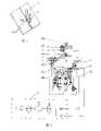
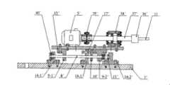
图1是本发明的工作原理示意图,图2是本发明的整体结构示意图,图3是前摩擦杆装配装置24的结构示意图,图4是后摩擦杆装配装置25的结构示意图,图5是具体实施方式六所述随焊摩擦挤压控制焊接应力变形的装置结构示意图,图6是图5的左视图。Fig. 1 is a schematic diagram of the working principle of the present invention, Fig. 2 is a schematic diagram of the overall structure of the present invention, Fig. 3 is a schematic structural diagram of the front frictionrod assembly device 24, Fig. 4 is a structural schematic diagram of the rear frictionrod assembly device 25, and Fig. 5 is a specific The sixth embodiment is a schematic structural diagram of a device for controlling welding stress and deformation with welding friction and extrusion. FIG. 6 is a left side view of FIG. 5 .

具体实施方式Detailed ways

具体实施方式一:(参见图2、图5)本实施方式由支撑座1、升降螺杆2、升降板3、两个结构相同的前摩擦杆装配装置24和一个后摩擦杆装配装置25组成,支撑座1通过升降螺杆2与升降板3连接,使用时可以在升降螺杆2上设置用于转动的手柄22;在升降板3的下方设有固定平台4,在所述固定平台4的下方设有两个结构相同的前摩擦杆装配装置24和一个后摩擦杆装配装置25,两个前摩擦杆装配装置24并排设置在固定平台的一端,所述后摩擦杆装配装置25设置在两个前摩擦杆装配装置24后部的中间位置,所述两个前摩擦杆装配装置24和后摩擦杆装配装置25的端面都与驱动装置10连接;所述两个前摩擦杆6之间形成的角度可依据焊缝宽度和焊缝余高的形状来确定,一般为30-60度,当焊缝宽度较宽且焊缝余高较大时,两个前摩擦杆6之间形成的角度取下限,反之,则取上限。Specific embodiment one: (see Fig. 2, Fig. 5) this embodiment is made up ofsupport base 1,lifting screw rod 2,lifting plate 3, two front frictionrod assembly devices 24 with the same structure and a rear frictionrod assembly device 25, Thesupport base 1 is connected with thelifting plate 3 by thelifting screw rod 2, and ahandle 22 for rotation can be set on thelifting screw rod 2 during use; There are two front frictionrod assembly devices 24 and one rear frictionrod assembly device 25 with the same structure, the two front frictionrod assembly devices 24 are arranged side by side at one end of the fixed platform, and the rear frictionrod assembly device 25 is arranged At the middle position of the rear part of the frictionrod assembly device 24, the end faces of the two front frictionrod assembly devices 24 and the rear frictionrod assembly device 25 are all connected to thedriving device 10; the angle formed between the twofront friction rods 6 It can be determined according to the shape of the weld width and weld reinforcement, generally 30-60 degrees. When the weld width is wide and the weld reinforcement is large, the angle formed between the twofront friction bars 6 takes the lower limit , otherwise, take the upper limit.

所述支撑座1通过升降螺杆2与升降板3连接的具体结构为:参照图5,所述升降板3下端设有中心阶梯孔3-1,中心阶梯孔3-1内装有推力轴承19,所述升降螺杆2的下端设有轴肩,轴肩设置在推力轴承19的下端;所述支撑座1上设有螺母1-1,所述升降螺杆2与支撑座1上的螺母1-1配合连接。The specific structure of thesupport base 1 connected with thelifting plate 3 through thelifting screw 2 is as follows: Referring to Figure 5, the lower end of thelifting plate 3 is provided with a central stepped hole 3-1, and a thrust bearing 19 is housed in the central stepped hole 3-1. The lower end of thelifting screw 2 is provided with a shoulder, and the shoulder is arranged on the lower end of the thrust bearing 19; thesupport base 1 is provided with a nut 1-1, and thelifting screw 2 and the nut 1-1 on thesupport base 1 Mate connection.

所述前摩擦杆装配装置24包括一号电机5和与一号电机5的输出轴同轴连接的前摩擦杆6;前摩擦杆装配装置24还包括一号下底板7和与一号下底板7固定连接的一号导柱8,所述一号电机5固定在一号上底板13上,一号上底板13上固定有两个滑座,分别为一号滑座9-1和二号滑座9-2,所述两个滑座设置在一号导柱8上;所述前摩擦杆装配装置24通过一号下底板7与固定平台4连接;The front frictionbar assembly device 24 includes the No. 1motor 5 and thefront friction bar 6 coaxially connected with the output shaft of the No. 1motor 5; the front frictionbar assembly device 24 also includes the No. 1lower base plate 7 and the No. 1lower base plate 7. The No. 1guide column 8 fixedly connected, the No. 1motor 5 is fixed on the No. 1upper base plate 13, and two sliding seats are fixed on the No. 1upper base plate 13, which are No. 1 sliding seat 9-1 and No. 2 sliding seat 9-1 respectively. The sliding seat 9-2, the two sliding seats are arranged on the No. 1guide post 8; the front frictionrod assembly device 24 is connected with thefixed platform 4 through the No. 1lower bottom plate 7;

所述后摩擦杆装配装置25包括二号电机5′和与二号电机5′的输出轴同轴连接的后摩擦杆11;后摩擦杆装配装置25还包括二号下底板7′和与二号下底板7′固定连接的二号导柱8′,所述二号电机5′固定在二号上底板13′上,二号上底板13′上固定有两个滑座,分别为三号滑座9-1′和四号滑座9-2′,所述两个滑座设置在二号导柱8′上;所述后摩擦杆装配装置25通过二号下底板7′与固定平台4连接;The rear frictionrod assembly device 25 includes the second motor 5' and therear friction rod 11 coaxially connected with the output shaft of the second motor 5'; the rear frictionrod assembly device 25 also includes the second bottom plate 7' and the second motor 5'. The No. 2 guide post 8' fixedly connected to the No. 2 lower base plate 7', the No. 2 motor 5' is fixed on the No. 2 upper base plate 13', and two sliding seats are fixed on the No. 2 upper base plate 13', which are respectively No. 3 Sliding seat 9-1' and No. 4 sliding seat 9-2', said two sliding seats are arranged on No. 4 connections;

所述两个前摩擦杆装配装置24的一号下底板7的端头通过加强板12进行相对位置固定。可以在固定平台4上设置三个连接件18,其中两个并排设置在固定平台的一侧,另一个连接件设置在另一侧的中间位置,所述两个前摩擦杆装配装置24上的一号下底板7分别通过心轴27与并排设置的两个连接件18连接,所述后摩擦杆装配装置25上的二号下底板7′与另一个连接件连接。所述连接件18与固定平台4的连接以及和加强板12与一号下底板7和二号下底板7′的连接可以是孔与长圆孔的连接,可通过调整该两处的螺栓在长圆孔上的位置来调整前摩擦杆6的倾斜角度,并保证随焊控制过程中两个前摩擦杆6能对称布置在焊缝中心的两侧,同时保证后摩擦杆11的轴线垂直于焊接工件表面并位于通过焊缝中心线的平面内,后摩擦杆11的摩擦端面与固定平台4下表面的距离通过摩擦杆的长短和装卡位置来调整。The ends of the No. 1lower bottom plate 7 of the two front frictionbar assembly devices 24 are fixed relative to each other through the reinforcingplate 12 . Threeconnectors 18 can be set on thefixed platform 4, two of which are arranged side by side on one side of the fixed platform, and the other connector is arranged in the middle of the other side, and the two front frictionrod assembly devices 24 The No. 1lower bottom plate 7 is respectively connected to two connectingpieces 18 arranged side by side through themandrel 27 , and the No. 2lower bottom plate 7 ′ on the rear frictionbar assembly device 25 is connected to the other connecting piece. The connection between the connectingpiece 18 and thefixed platform 4 and the connection between thereinforcement plate 12 and the No. 1lower base plate 7 and the No. 2 lower base plate 7' can be the connection between the hole and the oblong hole, and the two bolts can be adjusted in the oblong circle. The position on the hole is used to adjust the inclination angle of thefront friction rod 6, and ensure that the twofront friction rods 6 can be symmetrically arranged on both sides of the weld center during the welding control process, and at the same time ensure that the axis of therear friction rod 11 is perpendicular to the welding workpiece The surface is also located in the plane passing through the center line of the weld seam, and the distance between the friction end surface of therear friction rod 11 and the lower surface of thefixed platform 4 is adjusted by the length of the friction rod and the clamping position.

工作前,将支撑座1固定在工作台23上,调整两个前摩擦杆之间的对称倾斜的角度和后摩擦杆的垂直度,完成后,转动手柄22,使整个装置降下,使摩擦杆端面与待焊工件表面保持一定距离,前摩擦杆端面与工件表面的距离一般应小于焊缝余高的三分之一,后摩擦杆的端面与工件表面的距离一般应小于焊缝余高的三分之二,具体数值可根据焊缝的形状进行适当的调整。工作时,先引燃电弧施焊,待熔池出现后使焊接工件向电弧后方行进,紧接着开动一号电机5和二号电机5′并启动驱动装置10对焊缝进行随焊控制。两个前摩擦杆6紧随焊接电弧之后,并紧紧压在焊缝两侧的焊趾部位对焊缝金属进行旋转挤压。由于前摩擦杆6旋转挤压时,其端面对焊缝金属有一向焊缝中心挤压的横向分力,同时,前摩擦杆端面作用的区域离焊接熔池较近,温度较高,焊缝中心部位的温度高于焊趾部位温度,当受到挤压时塑性金属更容易向焊缝中心流动,这样前摩擦杆端面就对处于脆性温度区间的金属施加一个横向挤压应变,从而抵消能致裂的拉伸应变,达到防止焊接热裂纹的目的。后摩擦杆11垂直作用于焊缝部位,对冷却到脆性温度区间以下但仍处于高塑性状态的焊缝金属进行旋转挤压。后摩擦杆11的端面向下挤压旋转时,迫使焊缝金属向两侧流动,将焊缝金属在冷却过程中形成的纵向和横向压缩塑性变形以及由两前摩擦杆在焊缝中引起的横向压缩变形都充分延展,主要起到降低残余应力减小焊接变形的效果。Before work, fix thesupport seat 1 on theworkbench 23, adjust the angle of symmetrical inclination between the two front friction rods and the verticality of the rear friction rod, after completion, turn thehandle 22 to lower the whole device, and make the friction rod Keep a certain distance between the end face and the surface of the workpiece to be welded. The distance between the end face of the front friction rod and the surface of the workpiece should generally be less than one third of the weld reinforcement, and the distance between the end face of the rear friction rod and the surface of the workpiece should generally be less than one third of the weld reinforcement. Two-thirds, the specific value can be properly adjusted according to the shape of the weld. During work, first ignite the arc and perform welding, and after the molten pool appears, the welding workpiece is advanced to the rear of the arc, and then the No. 1motor 5 and the No. 2 motor 5' are started and thedriving device 10 is started to carry out follow-up welding control on the weld seam. The twofront friction rods 6 closely follow the welding arc and press tightly against the welding toes on both sides of the weld to rotate and squeeze the weld metal. When thefront friction rod 6 is rotated and extruded, its end faces the weld metal and has a lateral force that presses toward the center of the weld. The temperature at the center of the seam is higher than that at the weld toe. When squeezed, the plastic metal is more likely to flow to the center of the weld. In this way, the end face of the front friction rod exerts a transverse extrusion strain on the metal in the brittle temperature range, thereby offsetting the energy. Cracking tensile strain, to achieve the purpose of preventing welding hot cracks. Therear friction rod 11 acts vertically on the weld seam, and rotates and squeezes the weld metal that has cooled below the brittle temperature range but is still in a high plastic state. When the end face of therear friction rod 11 is squeezed and rotated downward, the weld metal is forced to flow to both sides, and the longitudinal and transverse compression plastic deformation of the weld metal formed during the cooling process and the deformation caused by the two front friction rods in the weld The transverse compression deformation is fully extended, which mainly plays the role of reducing residual stress and reducing welding deformation.

具体实施方式二:(参见图3、图4)本实施方式与具体实施方式一的不同点在于在一号下底板7上设有两个支座,分别为一号支座14-1和二号支座14-2,所述一号导柱8的两端通过一号支座14-1和二号支座14-2进行固定;在二号滑座9-2与二号支座14-2之间安装有压缩弹簧15。其它组成和连接关系与具体实施方式一相同。压缩弹簧15的作用在于可以适当地控制摩擦杆与焊缝之间的距离,工作时通过驱动装置10推动摩擦杆下降对焊缝施加压力,停止工作时驱动装置10停止对摩擦杆加压,则摩擦杆在压缩弹簧15的推动下弹起,避免不工作时摩擦杆的重力对焊缝加压而产生负面效果。Specific embodiment two: (see Fig. 3, Fig. 4) the difference between this embodiment and specific embodiment one is that there are two supports on the No. No. support 14-2, the two ends of the No. 1guide post 8 are fixed by No. 1 support 14-1 and No. 2 support 14-2; Acompression spring 15 is installed between -2. Other compositions and connections are the same as in the first embodiment. The function of thecompression spring 15 is to properly control the distance between the friction rod and the welding seam. When working, the drivingdevice 10 pushes the friction rod down to apply pressure to the welding seam. When the work stops, the drivingdevice 10 stops pressurizing the friction rod. The friction bar bounces up under the promotion of thecompression spring 15, so as to avoid negative effects caused by the gravity of the friction bar to pressurize the weld seam when not working.

具体实施方式三:(参见图3、图4)本实施方式与具体实施方式二不同之处在于,在一号支座14-1与二号支座14-2之间还设有三号支座14-3,三号支座14-3设置在一号滑座9-1和二号滑座9-2之间,在三号支座14-3与二号滑座9-2之间的一号导柱8上设有滑块16,在三号支座14-3上设有加压螺栓17。工作时,可以通过旋转加压螺栓17在三号支座上的前进度从而通过滑块16控制二号滑座9-2在一号导柱8上的位置,从而起到限制滑座及其连接部件的轴向位移和预紧弹簧的作用。Specific embodiment 3: (see Fig. 3, Fig. 4) The difference between this embodiment andspecific embodiment 2 is that a No. 3 support is also provided between No. 1 support 14-1 and No. 2 support 14-2 14-3, No. 3 support 14-3 is arranged between No. 1 slide seat 9-1 and No. 2 slide seat 9-2, between No. 3 support 14-3 and No. 2 slide seat 9-2A slide block 16 is provided on the No. 1guide post 8, and apressure bolt 17 is provided on the No. 3 support 14-3. During work, the position of No. 2 slider 9-2 on No. 1guide post 8 can be controlled byslider 16 by rotating the forward progress ofpressure bolt 17 on No. 3 support, thereby limiting the slider and its The axial displacement of the connecting parts and the action of the preload spring.

具体实施方式四:(参见图2-图4)本实施方式所述驱动装置10作用在一号电机5的端面上,所述驱动装置10是气缸,以气缸作为驱动装置具有方便操作容易控制的优点,直接作用在电机的端面上可以将力直接传递给摩擦杆,易于控制。实际操作时也可以使用液压缸代替气缸,也可以将力作用在上底板13上,也都可以实现本发明目的,因此都在本发明的保护范围之内。Specific embodiment four: (referring to Fig. 2-Fig. 4) described drivingdevice 10 of this embodiment acts on the end face of No. 1motor 5, and described drivingdevice 10 is a cylinder, has convenient operation and easy control with cylinder as driving device Advantages, directly acting on the end face of the motor can directly transmit the force to the friction rod, which is easy to control. Also can use hydraulic cylinder to replace air cylinder during actual operation, also can force on theupper base plate 13, also can realize the object of the present invention, therefore all within the scope of protection of the present invention.

具体实施方式五:(参见图5)本实施方式还增加有导柱20,在升降板3上还设有两个阶梯孔3-2,导柱20的下端通过阶梯孔3-2进行固定,所述支撑座1上设有供导柱20通过的孔。导柱20的作用在于可以使升降板3和固定平台4保持与升降螺杆2轴向一致的移动,避免了径向移动而可能导致摩擦杆不能有效对正焊缝而影响最终效果。Specific embodiment five: (referring to Fig. 5) this embodiment also increases guidepost 20, is also provided with two step holes 3-2 on liftingplate 3, the lower end ofguide post 20 is fixed by step hole 3-2, Thesupport base 1 is provided with a hole for theguide post 20 to pass through. The function of theguide post 20 is to keep the liftingplate 3 and the fixedplatform 4 moving in the same axial direction as the liftingscrew 2, avoiding the radial movement that may cause the friction rod to be unable to effectively align the weld seam and affect the final effect.

具体实施方式六:(参见图2、图3、图5和图6)本实施方式提供一种实现所述发明目的的详细装置结构,它由前摩擦杆装配装置24、后摩擦杆装配装置25、加强板12、螺栓26、连接件18、心轴27、固定平台4、螺栓28、升降板3、螺栓29、螺栓30、支撑座1、导柱20、螺栓31、透盖32、手柄22、螺母1-1、升降螺杆2、推力轴承19、紧定螺钉33、螺栓34、螺栓35和气动加压系统(驱动装置)10组成。标号23为工作台。前摩擦杆装配装置24通过心轴27与连接件18连接,连接件18通过螺栓28与固定平台4连接,升降板3通过螺栓29与固定平台4连接。升降板3上设有三个阶梯孔,正中间的阶梯孔3-1是为了装入推力轴承19和穿过升降螺杆2,升降螺杆2上设有轴肩,其挡在推力轴承19的紧圈上,两侧的阶梯孔3-2是为了穿过并固定导柱20。与升降螺杆2配合的螺母1-1嵌入支撑座1中并被紧定螺钉33紧定,其端面被透盖32用螺栓31轴向固定。支撑座1上设有两个导孔,其与两个导柱20配合。支撑座1通过螺栓30固定在工作台23的上表面。升降螺杆2的上端装有手柄22。后摩擦杆装配装置25通过螺栓35与连接件18连接固定,连接件18通过螺栓34连接在固定平台4上。两个前摩擦杆装配装置24参照整个装置的中心面对称布置,它们在末端处被加强板12通过螺栓26固定连接。本实施方式的压力来源由气动加压系统10提供,它是通过气动驱动元件(气缸)作用在电动机的端面或其它部位而产生摩擦杆端面对焊缝的挤压力。Specific Embodiment Six: (See Fig. 2, Fig. 3, Fig. 5 and Fig. 6) This embodiment provides a detailed device structure for realizing the purpose of the invention, which consists of a front frictionrod assembly device 24 and a rear frictionrod assembly device 25 ,reinforcement plate 12,bolt 26,connector 18,mandrel 27, fixedplatform 4,bolt 28, liftingplate 3,bolt 29,bolt 30,support seat 1, guidepost 20,bolt 31,transparent cover 32, handle 22 , nut 1-1, liftingscrew rod 2, thrustbearing 19, setscrew 33,bolt 34,bolt 35 and pneumatic pressurization system (driver) 10 to form.Label 23 is a workbench. The front frictionrod assembly device 24 is connected with the connectingpiece 18 through themandrel 27, the connectingpiece 18 is connected with the fixedplatform 4 through thebolt 28, and thelifting plate 3 is connected with the fixedplatform 4 through thebolt 29. The liftingplate 3 is provided with three stepped holes, the middle stepped hole 3-1 is for loading thethrust bearing 19 and passing through the liftingscrew 2, the liftingscrew 2 is provided with a shaft shoulder, which blocks the tight ring of thethrust bearing 19 Above, the stepped holes 3-2 on both sides are for passing through and fixing theguide post 20. The nut 1 - 1 cooperating with the liftingscrew 2 is embedded in thesupport seat 1 and is tightened by theset screw 33 , and its end surface is axially fixed by the throughcover 32 with thebolt 31 . Thesupport base 1 is provided with two guide holes, which cooperate with the two guide posts 20 . Thesupport base 1 is fixed on the upper surface of theworkbench 23 bybolts 30 . The upper end of liftingscrew rod 2 is equipped withhandle 22. The rear frictionrod assembly device 25 is connected and fixed to the connectingpiece 18 throughbolts 35 , and the connectingpiece 18 is connected to the fixedplatform 4 throughbolts 34 . The two front frictionbar assembly devices 24 are symmetrically arranged with reference to the central plane of the whole device, and they are fixedly connected by thereinforcement plate 12 at the ends bybolts 26 . The pressure source of the present embodiment is provided by thepneumatic pressurization system 10, which acts on the end face of the motor or other parts through the pneumatic drive element (air cylinder) to generate the extrusion force of the end face of the friction rod on the weld seam.

参照图3,前摩擦杆装配装置24由前摩擦杆6、一号夹头36、一号轴37、一号轴承座38、一号加压螺栓17、一号联轴器39、一号电机5、一号底板13、一号端盖40、一号支座14-1、二号支座14-2、三号支座14-3、一号滑座9-1、二号滑座9-2、一号导柱8、一号滑块16、一号压缩弹簧15和一号下底板7组成。一号电机5的输出轴通过一号联轴器39与一号轴37联结,一号轴37通过一号夹头36与前摩擦杆6连接,一号轴承座38、一号电机5、一号滑座9-1和二号滑座9-2通过螺栓固定在一号上底板13上,一号支座14-1、二号支座14-2、三号支座14-3通过螺栓固定在一号下底板7上。两根平行布置的一号导柱8由一号支座14-1、二号支座14-2和三号支座14-3支撑并由一号支座14-1、二号支座14-2和一号端盖40轴向定位。一号滑座9-1和二号滑座9-2通过其上的导孔坐在两根一号导柱8上,可带动一号上底板13及其连接部件在一号导柱8上滑动。二号滑座9-2和二号支座14-2间的导柱上放置有一号压缩弹簧15,一号加压螺栓17从三号支座14-3的螺孔旋入顶在一号滑块16的表面,推动二号支座14-2向前滑移,一号压缩压缩弹簧15从而起到限制二号滑座9-2及其连接部件的轴向位移和预紧弹簧的作用。Referring to Fig. 3, the front frictionrod assembly device 24 is composed of thefront friction rod 6, the No. 1chuck 36, the No. 5. No. 1bottom plate 13, No. 1end cover 40, No. 1 support 14-1, No. 2 support 14-2, No. 3 support 14-3, No. 1 sliding seat 9-1, No. 2 sliding seat 9 -2. The No. 1guide post 8, the No. 1slide block 16, the No. 1compression spring 15 and the No. 1bottom plate 7 are composed. The output shaft of the No. 1motor 5 is connected with the No. 1shaft 37 through the No. 1shaft coupling 39, and the No. 1shaft 37 is connected with thefront friction rod 6 through the No. 1chuck 36. The No. 1bearing block 38, the No. 1motor 5, and the No. 1 shaft No. 9-1 slide seat and No. 2 slide seat 9-2 are fixed on the No. 1upper base plate 13 by bolts, and No. 1 support 14-1, No. 2 support 14-2, and No. 3 support 14-3 are fixed by bolts Be fixed on No. 1bottom plate 7. Two No. 1guide pillars 8 arranged in parallel are supported by No. 1 support 14-1, No. 2 support 14-2 and No. 3 support 14-3, and are supported by No. 1 support 14-1 and No. 2 support 14. -2 and the No. 1end cap 40 are positioned axially. No. 1 sliding seat 9-1 and No. 2 sliding seat 9-2 sit on two No. 1guide posts 8 through the guide holes thereon, and can drive No. 1upper base plate 13 and its connecting parts on No. 1guide post 8 slide. A No. 1compression spring 15 is placed on the guide post between No. 2 sliding seat 9-2 and No. 2 support 14-2, and No. 1pressurizing bolt 17 is screwed into the screw hole of No. 3 support 14-3 and topped on No. 1 The surface of theslider 16 pushes the No. 2 bearing 14-2 to slide forward, and the No. 1 compresses thecompression spring 15 to play the role of limiting the axial displacement of the No. 2 slider 9-2 and its connecting parts and the pre-tension spring .

后摩擦杆装配装置25的结构与前摩擦杆装配装置24的结构相同,参照图4,后摩擦杆装配装置25由后摩擦杆11、二号夹头36′、二号轴37′、二号轴承座38′、二号加压螺栓17′、二号联轴器39′、二号电机5′、二号底板13′、二号端盖40′、四号支座14-1′、五号支座14-2′、六号支座14-3′、三号滑座9-1′、四号滑座9-2′、二号导柱8′、二号滑块16′、二号压缩弹簧15′和二号下底板7′组成。二号电机5′的输出轴通过二号联轴器39′与二号轴37′联结,二号轴37′通过二号夹头36′与后摩擦杆11连接,二号轴承座38′、二号电机5′、三号滑座9-1′和四号滑座9-2′通过螺栓固定在二号上底板13′上,四号支座14-1′、五号支座14-2′、六号支座14-3′通过螺栓固定在二号下底板7′上。两根平行布置的二号导柱8′由四号支座14-1′、五号支座14-2′和六号支座14-3′支撑并由四号支座14-1′、五号支座14-2′和二号端盖40′轴向定位。三号滑座9-1′和四号滑座9-2′通过其上的导孔坐在两根二号导柱8′上,可带动二号上底板13′及其连接部件在二号导柱8′上滑动。四号滑座9-2′和五号支座14-2′间的导柱上放置有二号压缩弹簧15′,二号加压螺栓17′从六号支座14-3′的螺孔旋入顶在二号滑块16′的表面,推动五号支座14-2′向前滑移,二号压缩压缩弹簧15′从而起到限制四号滑座9-2′及其连接部件的轴向位移和预紧弹簧的作用。The structure of the rear frictionrod assembly device 25 is the same as that of the front frictionrod assembly device 24. With reference to Fig. 4, the rear frictionrod assembly device 25 is composed ofrear friction rod 11, No. Bearing seat 38', No. 2 pressure bolt 17', No. 2 coupling 39', No. 2 motor 5', No. 2 bottom plate 13', No. 2 end cover 40', No. 4 support 14-1', No. 5 No. support 14-2', No. 6 support 14-3', No. 3 slide 9-1', No. 4 slide 9-2', No. 2 guide post 8', No. 2 slide 16', No. 2 No. compression spring 15 ' and No. two bottom plate 7 ' form. The output shaft of the No. 2 motor 5' is connected with the No. 2 shaft 37' through the No. 2 shaft coupling 39', and the No. 2 shaft 37' is connected with therear friction rod 11 through the No. 2 chuck 36'. The No. 2 bearing seat 38', No. 2 motor 5', No. 3 sliding seat 9-1' and No. 4 sliding seat 9-2' are fixed on No. 2 upper base plate 13' by bolts, No. 4 support 14-1', No. 5 support 14- 2', the No. 6 support 14-3' is fixed on the No. 2 lower base plate 7' by bolts. Two No. 2 guide columns 8' arranged in parallel are supported by No. 4 support 14-1', No. 5 support 14-2' and No. 6 support 14-3' and are supported by No. 4 support 14-1', The fifth support 14-2' and the second end cover 40' are positioned axially. No. 3 sliding seat 9-1' and No. 4 sliding seat 9-2' sit on two No. 2 guide posts 8' through the guide holes thereon, which can drive No. 2 upper base plate 13' and its connecting parts on No. 2 Slide on the guide post 8'. On the guide post between No. 4 sliding seat 9-2' and No. 5 support 14-2', No. 2 compression spring 15' is placed, and No. 2 pressurizing bolt 17' passes through the screw hole of No. 6 support 14-3'. Screw into the surface of the No. 2 slider 16', push the No. 5 support 14-2' to slide forward, and No. 2 compresses the compression spring 15' so as to limit the No. 4 slider 9-2' and its connecting parts The axial displacement and the effect of the preload spring.

Claims (8)

Translated fromChinese
1. 一种随焊摩擦挤压控制焊接应力变形的装置,其特征在于它包括支撑座(1)和与支撑座(1)通过升降螺杆(2)连接的升降板(3),在升降板(3)的下方设有固定平台(4),在所述固定平台(4)的下方设有两个结构相同的前摩擦杆装配装置(24)和一个后摩擦杆装配装置(25),两个前摩擦杆装配装置(24)并排设置在固定平台的一端,所述后摩擦杆装配装置(25)设置在两个前摩擦杆装配装置(24)后部的中间位置,所述两个前摩擦杆装配装置(24)和后摩擦杆装配装置(25)的端面都与驱动装置(10)连接;1. A device for controlling welding stress and deformation with welding friction and extrusion, characterized in that it includes a support base (1) and a lifting plate (3) connected with the support base (1) through a lifting screw (2). (3) is provided with a fixed platform (4) below the fixed platform (4), and two front friction rod assembly devices (24) and a rear friction rod assembly device (25) with the same structure are provided under the fixed platform (4). Two front friction bar assembly devices (24) are arranged side by side at one end of the fixed platform, and the rear friction bar assembly device (25) is arranged at the middle position of the rear parts of the two front friction bar assembly devices (24). The end faces of the friction rod assembly device (24) and the rear friction rod assembly device (25) are all connected with the driving device (10);所述前摩擦杆装配装置(24)包括一号电机(5)和与一号电机(5)的输出轴同轴连接的前摩擦杆(6);前摩擦杆装配装置(24)还包括一号下底板(7)和与一号下底板(7)固定连接的一号导柱(8),所述一号电机(5)固定在一号上底板(13)上,一号上底板(13)上固定有两个滑座,分别为一号滑座(9-1)和二号滑座(9-2),所述两个滑座设置在一号导柱(8)上;所述前摩擦杆装配装置(24)通过一号下底板(7)与固定平台(4)连接;The front friction bar assembly device (24) includes a No. 1 motor (5) and a front friction bar (6) coaxially connected with the output shaft of the No. 1 motor (5); the front friction bar assembly device (24) also includes a The No. 1 lower base plate (7) and the No. 1 guide post (8) fixedly connected with the No. 1 lower base plate (7), the No. 1 motor (5) is fixed on the No. 1 upper base plate (13), and the No. 1 upper base plate ( 13) There are two sliding seats fixed on it, namely the No. 1 sliding seat (9-1) and the No. 2 sliding seat (9-2), and the two sliding seats are arranged on the No. 1 guide post (8); The front friction rod assembly device (24) is connected with the fixed platform (4) through the No. 1 lower base plate (7);所述后摩擦杆装配装置(25)包括二号电机(5′)和与二号电机(5′)的输出轴同轴连接的后摩擦杆(11);后摩擦杆装配装置(25)还包括二号下底板(7′)和与二号下底板(7′)固定连接的二号导柱(8′),所述二号电机(5′)固定在二号上底板(13′)上,二号上底板(13′)上固定有两个滑座,分别为三号滑座(9-1′)和四号滑座(9-2′),所述两个滑座设置在二号导柱(8′)上;所述后摩擦杆装配装置(25)通过二号下底板(7′)与固定平台(4)连接;The rear friction rod assembling device (25) comprises a No. 2 motor (5') and a rear friction rod (11) coaxially connected with the output shaft of the No. 2 motor (5'); the rear friction rod assembling device (25) also It includes the No. 2 lower base plate (7') and the No. 2 guide post (8') fixedly connected with the No. 2 lower base plate (7'), and the No. 2 motor (5') is fixed on the No. 2 upper base plate (13') On the No. 2 upper base plate (13'), there are two sliding seats fixed, namely the No. 3 sliding seat (9-1') and the No. 4 sliding seat (9-2'). The two sliding seats are set on On the No. 2 guide post (8'); the rear friction rod assembly device (25) is connected with the fixed platform (4) through the No. 2 lower base plate (7');所述两个前摩擦杆装配装置(24)的下底板(7)的端头通过加强板(12)进行相对位置固定。The ends of the lower bottom plates (7) of the two front friction bar assembly devices (24) are fixed in relative position through the reinforcing plate (12).2. 根据权利要求1所述的一种随焊摩擦挤压控制焊接应力变形的装置,其特征在于两个前摩擦杆(6)之间形成的角度为30-60度。2. A device for controlling welding stress deformation with welding friction extrusion according to claim 1, characterized in that the angle formed between the two front friction bars (6) is 30-60 degrees.3. 根据权利要求1或2所述的一种随焊摩擦挤压控制焊接应力变形的装置,其特征在于在一号下底板(7)上设有两个支座,分别为一号支座(14-1)和二号支座(14-2),所述一号导柱(8)的两端通过一号支座(14-1)和二号支座(14-2)进行固定;在二号滑座(9-2)与二号支座(14-2)之间安装有压缩弹簧(15)。3. A device for controlling welding stress deformation with welding friction and extrusion according to claim 1 or 2, characterized in that two supports are provided on the No. 1 lower bottom plate (7), which are No. 1 supports respectively (14-1) and No. 2 support (14-2), the two ends of the No. 1 guide post (8) are fixed by No. 1 support (14-1) and No. 2 support (14-2) ; A compression spring (15) is installed between No. two sliding seat (9-2) and No. two support (14-2).4. 根据权利要求3所述的一种随焊摩擦挤压控制焊接应力变形的装置,其特征在于在一号支座(14-1)与二号支座(14-2)之间还设有三号支座(14-3),三号支座(14-3)设置在一号滑座(9-1)和二号滑座(9-2)之间,在三号支座(14-3)与二号滑座(9-2)之间的一号导柱(8)上设有滑块(16),在三号支座(14-3)上设有加压螺栓(17)。4. A device for controlling welding stress deformation with welding friction extrusion according to claim 3, characterized in that there is also a set between No. There are No. 3 bearings (14-3), and No. 3 bearings (14-3) are arranged between No. 1 sliding seat (9-1) and No. 2 sliding seat (9-2), and No. 3 bearings (14 -3) There is a slide block (16) on the No. 1 guide column (8) between No. 2 slide seat (9-2), and a pressure bolt (17) is provided on the No. ).5. 根据权利要求1、2或4所述的一种随焊摩擦挤压控制焊接应力变形的装置,其特征在于所述驱动装置(10)作用在一号电机(5)的端面上,所述驱动装置(10)是气缸。5. A device for controlling welding stress deformation with welding friction extrusion according to claim 1, 2 or 4, characterized in that said driving device (10) acts on the end face of No. 1 motor (5), so Said driving device (10) is an air cylinder.6. 根据权利要求1、2或4所述的一种随焊摩擦挤压控制焊接应力变形的装置,其特征在于支撑座(1)通过升降螺杆(2)与升降板(3)连接的具体结构为:所述升降板(3)下端设有中心阶梯孔(3-1),中心阶梯孔(3-1)内装有推力轴承(19),所述升降螺杆(2)的下端设有轴肩,轴肩设置在推力轴承(19)的下端;所述支撑座(1)上设有螺母(1-1),所述升降螺杆(2)与支撑座(1)上的螺母(1-1)配合连接。6. A device for controlling welding stress deformation with welding friction extrusion according to claim 1, 2 or 4, characterized in that the support base (1) is connected with the lifting plate (3) through the lifting screw (2) The structure is: the lower end of the lifting plate (3) is provided with a central stepped hole (3-1), the central stepped hole (3-1) is equipped with a thrust bearing (19), and the lower end of the lifting screw (2) is provided with a shaft Shoulder, the shaft shoulder is arranged on the lower end of the thrust bearing (19); the nut (1-1) is provided on the support base (1), and the nut (1-1) on the support base (1) is connected with the lifting screw (2) 1) Mating connection.7. 根据权利要求1所述的一种随焊摩擦挤压控制焊接应力变形的装置,其特征在于它还包括导柱(20),在升降板(3)上还设有两个阶梯孔(3-2),导柱(20)的下端通过阶梯孔(3-2)进行固定,所述支撑座(1)上设有供导柱(20)通过的孔。7. A device for controlling welding stress deformation with welding friction extrusion according to claim 1, characterized in that it also includes guide posts (20), and two stepped holes ( 3-2), the lower end of the guide post (20) is fixed through the stepped hole (3-2), and the support seat (1) is provided with a hole for the guide post (20) to pass through.8. 根据权利要求1、2或4所述的一种随焊摩擦挤压控制焊接应力变形的装置,其特征在于在固定平台(4)上设有三个连接件(18),其中两个并排设置在固定平台的一侧,另一个连接件设置在另一侧的中间位置,所述两个前摩擦杆装配装置(24)上的一号下底板(7)分别通过心轴(27)与并排设置的两个连接件(18)连接,所述后摩擦杆装配装置(25)上的二号下底板(7′)与另一个连接件连接。8. A device for controlling welding stress deformation with welding friction extrusion according to claim 1, 2 or 4, characterized in that three connectors (18) are arranged on the fixed platform (4), two of which are side by side It is arranged on one side of the fixed platform, and the other connecting piece is arranged in the middle of the other side. The No. 1 lower bottom plate (7) on the two front friction bar assembly devices (24) passes through the mandrel (27) and the The two connecting pieces (18) arranged side by side are connected, and the No. 2 lower bottom plate (7') on the rear friction bar assembly device (25) is connected with another connecting piece.
CNB2006101508524A2006-09-292006-09-29 A device for controlling welding stress and deformation with welding friction extrusionExpired - Fee RelatedCN100413635C (en)

Priority Applications (1)

Application NumberPriority DateFiling DateTitle
CNB2006101508524ACN100413635C (en)2006-09-292006-09-29 A device for controlling welding stress and deformation with welding friction extrusion

Applications Claiming Priority (1)

Application NumberPriority DateFiling DateTitle
CNB2006101508524ACN100413635C (en)2006-09-292006-09-29 A device for controlling welding stress and deformation with welding friction extrusion

Publications (2)

Publication NumberPublication Date
CN1927530A CN1927530A (en)2007-03-14
CN100413635Ctrue CN100413635C (en)2008-08-27

Family

ID=37857750

Family Applications (1)

Application NumberTitlePriority DateFiling Date
CNB2006101508524AExpired - Fee RelatedCN100413635C (en)2006-09-292006-09-29 A device for controlling welding stress and deformation with welding friction extrusion

Country Status (1)

CountryLink
CN (1)CN100413635C (en)

Families Citing this family (5)

* Cited by examiner, † Cited by third party
Publication numberPriority datePublication dateAssigneeTitle
CN101138817B (en)*2007-10-122010-04-21哈尔滨工业大学 A device for controlling welding stress and deformation by rotating and extruding with welding impact
CN101554693B (en)*2009-05-152011-05-04哈尔滨工业大学Device for controlling welding stress deformation by welding with point-to-point extrusion
CN101786212B (en)*2010-03-242012-03-07中国电子科技集团公司第二研究所Mechanical compaction welding set for processing laminated ceramic chips
CN102728972A (en)*2012-06-062012-10-17辽宁工程技术大学Control device for residual stress and strain along with welding of titanium alloy
CN103817452B (en)*2014-03-182015-10-28哈尔滨工业大学A kind of trailing peening method of multi-pass welding

Citations (10)

* Cited by examiner, † Cited by third party
Publication numberPriority datePublication dateAssigneeTitle
JPS5956988A (en)*1982-09-281984-04-02Setsuya FujiwakaMethod and device for decreasing welding strain in welded annular pipe by plural torches
CN87100959A (en)*1987-02-281988-09-07航空工业部六二五研究所 Low stress non-deformation welding method and device for thin plate members
CN1075277A (en)*1993-02-251993-08-18北京航空工艺研究所Dynamically control thin-plate element low stress does not have distortion welding and device thereof
JPH07236994A (en)*1994-02-281995-09-12Toshiba Corp Welding distortion prevention method and apparatus
CN1313159A (en)*1997-07-232001-09-19株式会社日立制作所Friction stirring welding method, frame component therefor and products hterefrom
CN1369336A (en)*2001-02-152002-09-18株式会社日立制作所Friction stirring connecting method of structural body, structural body and extruded bar section
JP2004017105A (en)*2002-06-182004-01-22Tadano LtdMethod and apparatus for relieving welding distortion in long size welded structure having box section
JP2004114064A (en)*2002-09-242004-04-15Toshiba Corp Method and apparatus for controlling welding deformation of welded structure
CN1490116A (en)*2003-08-262004-04-21哈尔滨工业大学 A device for controlling welding stress and deformation with welding impact rolling
CN1739902A (en)*2005-09-282006-03-01中国航空工业第一集团公司北京航空制造工程研究所Medium cooling, stirring and rubbing welding method and device

Patent Citations (10)

* Cited by examiner, † Cited by third party
Publication numberPriority datePublication dateAssigneeTitle
JPS5956988A (en)*1982-09-281984-04-02Setsuya FujiwakaMethod and device for decreasing welding strain in welded annular pipe by plural torches
CN87100959A (en)*1987-02-281988-09-07航空工业部六二五研究所 Low stress non-deformation welding method and device for thin plate members
CN1075277A (en)*1993-02-251993-08-18北京航空工艺研究所Dynamically control thin-plate element low stress does not have distortion welding and device thereof
JPH07236994A (en)*1994-02-281995-09-12Toshiba Corp Welding distortion prevention method and apparatus
CN1313159A (en)*1997-07-232001-09-19株式会社日立制作所Friction stirring welding method, frame component therefor and products hterefrom
CN1369336A (en)*2001-02-152002-09-18株式会社日立制作所Friction stirring connecting method of structural body, structural body and extruded bar section
JP2004017105A (en)*2002-06-182004-01-22Tadano LtdMethod and apparatus for relieving welding distortion in long size welded structure having box section
JP2004114064A (en)*2002-09-242004-04-15Toshiba Corp Method and apparatus for controlling welding deformation of welded structure
CN1490116A (en)*2003-08-262004-04-21哈尔滨工业大学 A device for controlling welding stress and deformation with welding impact rolling
CN1739902A (en)*2005-09-282006-03-01中国航空工业第一集团公司北京航空制造工程研究所Medium cooling, stirring and rubbing welding method and device

Also Published As

Publication numberPublication date
CN1927530A (en)2007-03-14

Similar Documents

PublicationPublication DateTitle
CN212371092U (en)Clamping and rotating device for forging processing
CN101890603B (en)Device for trimming weld with trailing impact rolling of high-strength low-matching equivalent-load welding joint
CN103008893B (en)Laser tailor welding method for stainless steel plate and fixing device for laser tailor welding
CN107570860B (en) A Welding Device for Butt Longitudinal Seam Welding for Vertical Assembly of Arc Wall Plates
CN101138817B (en) A device for controlling welding stress and deformation by rotating and extruding with welding impact
CN100413635C (en) A device for controlling welding stress and deformation with welding friction extrusion
CN103692070B (en)Welding method
CN101618479A (en)Control method of stir friction welding seam deformation
CN106903432B (en)Based on the laser assembly solder device and its control method rolled with weldering
CN202037785U (en)Horizontal solar foaming clamp vehicle
CN111136394B (en)Two-way welding jig that laser welding used
CN103692063B (en)A kind of Novel welding device
CN203649621U (en)Novel welding device
CN201950392U (en)Equipment for manufacturing surfacing welded composite wear-resistant steel sheet
CN214444284U (en)Clamping device for welding
CN102728972A (en)Control device for residual stress and strain along with welding of titanium alloy
CN112276309A (en)Four-gun automatic welding device for hydraulic torque converter assembly
CN103521902B (en)Weld seam force application apparatus and utilize this device to improve the method for weld seam form and performance
CN112756428A (en)Solid-web steel beam web amplitude deformation correction tool and correction method thereof
CN208960677U (en)A kind of device rebuild for welding back part
CN113084379A (en)Device and method for regulating and controlling residual stress and deformation after welding
CN211248942U (en) Universal tool for assembly and welding of coupler beam
CN212598630U (en)Forging equipment with high forging uniformity
CN203610829U (en)Submerged-arc welding pipe welding line form and performance improving device
CN113275722A (en)Vertical butt welding machine

Legal Events

DateCodeTitleDescription
C06Publication
PB01Publication
C10Entry into substantive examination
SE01Entry into force of request for substantive examination
C14Grant of patent or utility model
GR01Patent grant
C17Cessation of patent right
CF01Termination of patent right due to non-payment of annual fee

Granted publication date:20080827

Termination date:20110929


[8]ページ先頭

©2009-2025 Movatter.jp