CN100413619C - Quick chuck and portable machine tool - Google Patents
Quick chuck and portable machine toolDownload PDFInfo
- Publication number
- CN100413619C CN100413619CCNB2004100452005ACN200410045200ACN100413619CCN 100413619 CCN100413619 CCN 100413619CCN B2004100452005 ACNB2004100452005 ACN B2004100452005ACN 200410045200 ACN200410045200 ACN 200410045200ACN 100413619 CCN100413619 CCN 100413619C
- Authority
- CN
- China
- Prior art keywords
- quick chuck
- spring
- locking
- tool
- clamping
- Prior art date
- Legal status (The legal status is an assumption and is not a legal conclusion. Google has not performed a legal analysis and makes no representation as to the accuracy of the status listed.)
- Expired - Fee Related
Links
Images


Classifications
- B—PERFORMING OPERATIONS; TRANSPORTING
- B23—MACHINE TOOLS; METAL-WORKING NOT OTHERWISE PROVIDED FOR
- B23B—TURNING; BORING
- B23B31/00—Chucks; Expansion mandrels; Adaptations thereof for remote control
- B23B31/02—Chucks
- B23B31/10—Chucks characterised by the retaining or gripping devices or their immediate operating means
- B23B31/12—Chucks with simultaneously-acting jaws, whether or not also individually adjustable
- B23B31/1207—Chucks with simultaneously-acting jaws, whether or not also individually adjustable moving obliquely to the axis of the chuck in a plane containing this axis
- B23B31/123—Chucks with simultaneously-acting jaws, whether or not also individually adjustable moving obliquely to the axis of the chuck in a plane containing this axis with locking arrangements
- B—PERFORMING OPERATIONS; TRANSPORTING
- B23—MACHINE TOOLS; METAL-WORKING NOT OTHERWISE PROVIDED FOR
- B23B—TURNING; BORING
- B23B2231/00—Details of chucks, toolholder shanks or tool shanks
- B23B2231/06—Chucks for handtools having means for opening and closing the jaws using the driving motor of the handtool
- B—PERFORMING OPERATIONS; TRANSPORTING
- B23—MACHINE TOOLS; METAL-WORKING NOT OTHERWISE PROVIDED FOR
- B23B—TURNING; BORING
- B23B2231/00—Details of chucks, toolholder shanks or tool shanks
- B23B2231/38—Keyless chucks for hand tools
- Y—GENERAL TAGGING OF NEW TECHNOLOGICAL DEVELOPMENTS; GENERAL TAGGING OF CROSS-SECTIONAL TECHNOLOGIES SPANNING OVER SEVERAL SECTIONS OF THE IPC; TECHNICAL SUBJECTS COVERED BY FORMER USPC CROSS-REFERENCE ART COLLECTIONS [XRACs] AND DIGESTS
- Y10—TECHNICAL SUBJECTS COVERED BY FORMER USPC
- Y10T—TECHNICAL SUBJECTS COVERED BY FORMER US CLASSIFICATION
- Y10T279/00—Chucks or sockets
- Y10T279/17—Socket type
- Y10T279/17615—Obliquely guided reciprocating jaws
- Y10T279/17623—Threaded sleeve and jaw
- Y10T279/17632—Conical sleeve
- Y—GENERAL TAGGING OF NEW TECHNOLOGICAL DEVELOPMENTS; GENERAL TAGGING OF CROSS-SECTIONAL TECHNOLOGIES SPANNING OVER SEVERAL SECTIONS OF THE IPC; TECHNICAL SUBJECTS COVERED BY FORMER USPC CROSS-REFERENCE ART COLLECTIONS [XRACs] AND DIGESTS
- Y10—TECHNICAL SUBJECTS COVERED BY FORMER USPC
- Y10T—TECHNICAL SUBJECTS COVERED BY FORMER US CLASSIFICATION
- Y10T279/00—Chucks or sockets
- Y10T279/17—Socket type
- Y10T279/17615—Obliquely guided reciprocating jaws
- Y10T279/17658—Reciprocating jaw advancing sleeve
- Y—GENERAL TAGGING OF NEW TECHNOLOGICAL DEVELOPMENTS; GENERAL TAGGING OF CROSS-SECTIONAL TECHNOLOGIES SPANNING OVER SEVERAL SECTIONS OF THE IPC; TECHNICAL SUBJECTS COVERED BY FORMER USPC CROSS-REFERENCE ART COLLECTIONS [XRACs] AND DIGESTS
- Y10—TECHNICAL SUBJECTS COVERED BY FORMER USPC
- Y10T—TECHNICAL SUBJECTS COVERED BY FORMER US CLASSIFICATION
- Y10T279/00—Chucks or sockets
- Y10T279/32—Means to prevent jaw loosening
Landscapes
- Engineering & Computer Science (AREA)
- Mechanical Engineering (AREA)
- Gripping On Spindles (AREA)
- Percussive Tools And Related Accessories (AREA)
Abstract
Description
Translated fromChinese技术领域technical field
本发明涉及一种快速卡盘、尤其是用于便携式工具机。The invention relates to a quick chuck, especially for portable power tools.
背景技术.Background technique.
DE 101 09 490 A1公开了一种用于便携式工具机的上述类型的快速卡盘,它具有一个用于控制止动装置的控制装置,止动装置用于承受夹紧支承力。该快速卡盘有一个轴向移动的操作件,该操作件与控制装置的一个可摆动地被支承的锁紧钮联接。如果操作件在背离快速卡盘的容纳区域的轴向被向后移动,锁紧钮被摆动,由此通过一个传递装置在盘形弹簧组成的止动装置和快速卡盘的基体之间形成一个构成传力链的连接,用于承受夹紧支承力。DE 101 09 490 A1 discloses a quick chuck of the above-mentioned type for a portable machine tool, which has a control device for controlling a stop device for bearing the clamping support force. The quick chuck has an axially displaceable actuating part which is coupled to a pivotably mounted locking knob of the control device. If the operating part is moved backwards in the axial direction away from the receiving area of the quick chuck, the locking button is swiveled, thus forming a gap between the stop device consisting of a disc spring and the base body of the quick chuck via a transmission device. The connection that forms the force transmission chain and is used to bear the clamping support force.
发明内容Contents of the invention
本发明涉及一种快速卡盘,特别是用于便携式工具机的快速卡盘,它具有一个操作件和控制装置,该控制装置包括至少一个用于控制至少一个止动装置的装置,该止动装置承受夹紧支承力。The invention relates to a quick chuck, in particular a quick chuck for a portable machine tool, which has an operating element and a control device, the control device including at least one device for controlling at least one stop device, the stop The device bears the clamping support force.
根据本发明,提出一种快速卡盘,用于便携式工具机,它具有一个操作件和控制装置,它包括至少一个用于控制至少一个止动装置的装置,该止动装置用来承受夹紧支承力,其中,通过所述可由该控制装置控制的止动装置可形成用于承受夹紧支承力的形状配合连接,其中,用于形成所述形状配合连接的止动装置可相对于基体旋转,其中,基体具有至少一个滑动面,止动装置在其上轴向可移动。According to the invention, a quick chuck is proposed for a portable machine tool, which has an operating part and a control device, which includes at least one device for controlling at least one stop device, which is used to withstand clamping Bearing force, wherein a form-fit connection for bearing clamping support forces can be formed by means of the stop device controllable by the control device, wherein the stop device for forming the form-fit connection is rotatable relative to the base body , wherein the base body has at least one sliding surface on which the stop device is axially displaceable.
在此建议,通过所述可由该控制装置控制的止动装置可形成用于承受夹紧支承力的形状配合连接。可获得能特别舒适和简单地操作的快速卡盘。还能避免用于止动装置的力作用固定所需要的大的操作力,达到在长的寿命上止动装置的较少磨损。能达到高的冲击钻孔强度,并且刀具能用一个适合于冲击钻孔工作的高的夹紧力可靠地固定在该快速卡盘中。此外,能简单地保证加工步骤的规定次序,由此可避免由多部件组成的操作装置和/或需由操作者做的复杂的操作顺序。It is proposed here that a form-fit connection for absorbing the clamping bearing force can be formed by means of the locking device which can be controlled by the control device. Quick chucks are available which are particularly comfortable and easy to handle. The high actuating forces required for force-action fixing of the locking device can also be avoided, resulting in less wear of the locking device over a long service life. High percussion drilling strength can be achieved, and the tool can be securely fixed in the quick chuck with a high clamping force suitable for percussion drilling work. In addition, a defined sequence of processing steps can be ensured in a simple manner, whereby handling devices consisting of multiple parts and/or complex operating sequences to be carried out by an operator can be avoided.
有利的是,止动装置相对于基体可旋转,用于形成形状配合连接,尤其沿着圆周方向可旋转。因而该形状配合连接能通过止动装置旋转来实现。It is advantageous if the locking device is rotatable relative to the base body for forming a form-fit connection, in particular in the circumferential direction. The form-fit connection can thus be achieved by rotation of the locking device.
一个安全和可靠的止动装置控制可这样实现,即由锁紧弹簧构成所述装置。这里锁紧弹簧可由普通技术人员认为合适的各种类型弹簧构成,例如螺旋压力弹簧等等。如果锁紧弹簧具有基本上环状的构型,它特别能节省空间地被集成上。A safe and reliable control of the locking device can be achieved in that the device is formed by a locking spring. Here, the locking spring can be formed by various types of springs considered appropriate by those skilled in the art, such as helical pressure springs and the like. If the locking spring has a substantially annular configuration, it can be integrated in a space-saving manner in particular.
如果刀具可通过一个可被操作件操作的弹簧装置间接地夹紧,卡盘的可靠性能被提高。如果用于将刀具间接夹紧的弹簧装置具有基本上环状的构型,则该装置对灰尘不敏感。对此,弹簧装置最好至少具有两个在圆周的相反侧上的用于在操作件中止动的卡接件。能有利地夹紧具有很大不同直径大小的刀具,例如从1.5毫米至13毫米。The reliability of the chuck can be increased if the tool can be clamped indirectly via a spring device which can be operated by the operating member. If the spring device for the indirect clamping of the tool has an essentially ring-shaped configuration, it is insensitive to dust. For this purpose, the spring device preferably has at least two catches on opposite sides of the circumference for locking in the actuating part. Tools with very different diameter sizes, for example from 1.5 mm to 13 mm, can advantageously be clamped.
本发明的有益的进一步构型是,操作件至少在一段操作范围内与止动装置可在作用方面脱联。紧的公差和由此联系的不希望有的影响,如高的制造费用,灰尘敏感性等等即可避免。它能有利地首先锁住,然后夹紧。如果操作件通过锁紧弹簧与所述装置可联接和脱联,则特别能达到设计上简单的解决方案。An advantageous further development of the invention is that the actuating element can be functionally decoupled from the locking device at least in an actuating range. Tight tolerances and the undesired effects associated therewith, such as high manufacturing costs, dust sensitivity, etc., can be avoided. It can advantageously be locked first and then clamped. A solution that is particularly simple in design is achieved if the actuating part can be coupled and decoupled from the device via a locking spring.
如果用于将刀具夹紧的操作件可转动地被支承,结构简单,特别是螺纹连接可得到有利的传动比,可用小的操作力获得大的夹紧力。在夹紧时通过控制装置就能简单地使操作件只要转动少于250度就可特别舒服地夹紧刀具了。然而原则上还会想到可用杠杆机构等替代螺纹连接。If the operating element for clamping the tool is mounted rotatably, the structure is simple, especially the threaded connection can obtain a favorable transmission ratio, and a large clamping force can be obtained with a small operating force. During clamping, the control device can simply rotate the operating part by less than 250 degrees, and the tool can be clamped particularly comfortably. In principle, however, it is also conceivable to use a lever mechanism or the like instead of the threaded connection.
操作件在轴向上被可移动地支承是有利的,由此可对于快速移动对应一个轴向操作,并且能达到简单不言自明的操作。有利的是,基体至少具有一个滑动面,止动装置可在其上轴向移动。Advantageously, the actuating part is mounted displaceably in the axial direction, whereby an axial actuation can be assigned to the rapid movement and a simple and self-explanatory operation can be achieved. Advantageously, the basic body has at least one sliding surface on which the locking device is axially displaceable.
在另一构型中建议,快速卡盘具有至少一个在至少一个工作位置上被一个弹簧元件轴向加载荷的夹爪。快速卡盘能自动闭合至一个规定程度,这提高了舒适度。有利的是,快速卡盘至少具有一个夹爪,它在至少一个工作状态中被一个装置在径向、特别是在径向向内加载荷。由此能可靠避免夹爪的不希望的卡死。该装置在这里由具有一个斜面的传递装置和/或由一个弹簧装置等构成。In a further embodiment it is proposed that the quick chuck has at least one clamping jaw which is axially loaded by a spring element in at least one working position. The quick chuck closes automatically to a defined degree, which increases comfort. Advantageously, the quick chuck has at least one clamping jaw, which is loaded radially, in particular radially inwards, by a device in at least one operating state. Undesirable jamming of the jaws can thereby be reliably avoided. The device is here formed by a transfer device with a ramp and/or by a spring device or the like.
有利的是,操作件经锁紧弹簧与基体可联接和脱联。Advantageously, the actuating element can be coupled and decoupled from the base body via a locking spring.
此外提出了一种便携式工具机,它具有一个快速卡盘,在该便携式工具机中,刀具通过一个可被操作件操作的弹簧装置夹紧。本发明特别有利地用于钻孔机,冲击钻机和/或拧螺丝机中。Furthermore, a portable power tool is proposed which has a quick chuck, in which the tool is clamped by a spring device which can be actuated by an operating element. The invention is particularly advantageously used in drilling machines, hammer drills and/or screwdrivers.
附图说明Description of drawings
其它优点在以下附图说明中给出。在附图中示出了本发明的一个实施例。附图,说明书和权利要求书包含了多个特征组合。普通技术人员可对这些特征有目的地单独看待,也可有意义地进一步组合起来。Further advantages are given in the following description of the figures. An exemplary embodiment of the invention is shown in the drawing. The drawings, description and claims contain numerous features in combination. A person skilled in the art can consider these features individually or in meaningful further combinations.
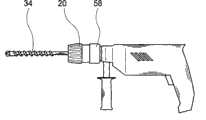
图1一个具有本发明快速卡盘的冲击钻机,Fig. 1 a percussion drill with quick chuck of the present invention,
图2一个带有刀具的本发明快速卡盘斜向上纵剖图,该刀具具有小直径,Fig. 2 is a longitudinal sectional view obliquely upwards of the quick chuck of the present invention with a cutter, the cutter has a small diameter,
图3是图2快速卡盘的细节图,具有可看见的用于夹紧刀具的弹簧装置,Figure 3 is a detailed view of the quick chuck of Figure 2, with visible spring means for clamping the tool,
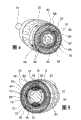
图4快速卡盘的IV-IV截面图,Figure 4 IV-IV sectional view of quick chuck,
图5快速卡盘的V-V截面图,Figure 5 V-V sectional view of the quick chuck,
图6相应于图4剖切快速卡盘的截面图,具有卡入的锁紧弹簧,FIG. 6 corresponds to FIG. 4 through a cross-sectional view of the quick chuck with snap-in locking springs,
图7相应于图5剖切快速卡盘的截面图,具有在反时针方向转动90度的操作件,Fig. 7 corresponds to the sectional view of Fig. 5 cutting the quick chuck, with the operating member rotated 90 degrees in the counterclockwise direction,
图8快速卡盘在止动和夹紧刀具时的截面图,Fig. 8 The cross-sectional view of the quick chuck when stopping and clamping the tool,
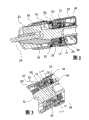
图9一个优选的基体的视图,和Figure 9 is a view of a preferred substrate, and
图10一个优选的止动装置的视图。Figure 10 is a view of a preferred stop device.
具体实施方式Detailed ways
图1示出了一个具有本发明快速卡盘及装有刀具34的冲击钻机,该刀具借助于一个操作件20可被止动和夹紧。操作件20的部分区域被覆盖套筒58包围。FIG. 1 shows a percussion drill with a quick chuck according to the invention and equipped with a
在附图中和说明书中基本上相同的部件原则上使用相同的参考标号。In principle, the same reference numerals are used for substantially the same components in the figures and in the description.
在图2至8中进一步说明的快速卡盘具有一个操作件20,该操作件在一个操作范围内可与一个固定套筒36在作用关系上脱联,确切地说,通过一个锁紧弹簧22(图4),在固定套简内固定有止动装置10,该锁紧弹簧由一个带状弹簧钢构成,基本上成环状以及设置在固定套筒36的一个圆周槽中。固定套筒36包围一个基体32,固定套筒的刀具近端的圆周小于它的刀具远端的圆周。刀具近端和刀具远端分别指固定套筒36的一个区域,它接近或远离已装刀具34,或者说设置得离用于刀具34的夹爪26近或远。在刀具近端,固定套筒36被一个由螺母构成的夹紧套筒50包围。与固定套筒36的刀具近端相邻设置了一个止推轴承52,它又和一个导向套筒42邻接。The quick chuck further explained in FIGS. ( FIG. 4 ), the
在固定套筒36的刀具远端上,不仅其外圆周而且其内径扩大了,其中约在固定套筒36的轴向中心构造了一个台阶状的扩大部分。在基体32和固定套筒36之间的如此构成的空腔内,在基体32的圆周上设置了一个或多个止动装置10。在固定套筒36的刀具远端上该固定套筒36围作用着一个固定环44,它和一个防脱环46一起阻止止动装置10脱出。在固定套筒36扩大的圆周上,与台肩毗邻,该固定套筒36被一个作为固定弹簧构成的弹簧装置12包围,其功能在以后的图5中做进一步说明。At the tool distal end of the
如果朝向自由端观察,该操作件20位于一个确定的、与一个打开位置对应的终端位置中,则止动装置10处于基体32的一个未详细画出的滑动面上。两个止动装置10在圆周方向上例如错开180度设置在相应的滑动面上。If the
如果刀具34要被插入快速卡盘,将操作件20在离开自由端方向沿轴向向后拉,由此,经导向套筒42在轴向与操作件20形状配合连接的夹爪26在离开自由端方向被向后和径向朝外操作。夹爪26张开,刀具34能被插入。If the
导向套筒42可轴向移动地支承在基体32上,并且经过一个未示出的键槽连接与基体32无相对转动地连接。也可行的是,将导向套筒42可转动地支承在基体32上,并且在夹爪26上获得导向套筒42的一个切向导向。The
如果刀具34已被插入夹爪26中,操作者松开操作件20,则它被一个构造成螺旋压力弹簧的弹性元件24向快速卡盘的自由端方向推。该螺旋压力弹簧构成的弹性元件24支撑在覆盖套筒58上,经固定环44作用在操作件20上,它又以一个轴向力经止推轴承52和导向套筒42作用在夹爪26上。通过该轴向力使得夹爪26沿基体32中的一些槽的斜面径向向内导行和用一个小的夹紧力固定刀具34。If the
在图3中图示了图2的快速卡盘的细节。该装置被这样转动,使得既看到用于夹紧刀具的弹簧装置12又能看到用于锁紧止动装置10的锁紧弹簧22。A detail of the quick chuck of FIG. 2 is illustrated in FIG. 3 . The device is turned in such a way that both the
关于相同的特征和功能基本上可参见图2中实施例的说明。基本上为环状的锁紧弹簧22径向向里穿过固定套筒36。Regarding the same features and functions, reference can basically be made to the description of the embodiment in FIG. 2 . The substantially
图4示出了沿着图3中线IV-IV剖切快速卡盘的横截面,这里观察方向是从固定套筒36的刀具远端至刀具近端。通过反时针方向转动操作件20,通过固定在操作件20的槽66中的锁紧弹簧22使固定套筒36转动,并且因此使止动装置10在基体32的圆周上移动。凸起30构成用于在槽66中的锁紧弹簧22的挡块。在松开位置,止动装置10位于基体32的一个滑动面64上,这些止动装置可在其上轴向移动。夹紧套筒50也同样跟着转动。最后止动装置10与基体32的齿48(图9)啮合。止动装置10通过与齿48啮合被轴向固定在基体32上。FIG. 4 shows a cross-section of the quick chuck taken along the line IV-IV in FIG. 3 , where the viewing direction is from the distal end of the fixed
一旦锁紧弹簧22用其指40卡入基体32的槽28中,被操作件20驱动的锁紧弹簧22的凸出部38从槽66中弹出并到达一个导出(auslaufende)槽68中。现在,在固定套筒36中的装入件通过锁紧弹簧22既在轴向又在径向相对基体32固定。As soon as the locking
当操作件20继续转动时仅仅只有夹紧套筒50经由固定弹簧构成的弹簧件12驱动,如在图5中作进一步说明的,在图5中示出了快速卡盘沿图3的V-V线的横截面。When the operating
弹簧装置12基本上由环状止动弹簧构成,具有两个大约相对地位于基体32的圆周上的卡接件14,16。卡接件14啮合到操作件20的槽70中并且以其在图中的右侧靠在操作件20的凸起76的一个边78上,该凸起在圆周方向远离卡接件14具有另一个边80。第二卡接件16啮合到操作件20的槽72中,并且具有第一止挡82和第二止挡84。槽72在远离卡接件16处由一个凸起86的边74构成边界。The
如图3中说明,当锁紧弹簧22已啮合到基体32的槽28中时,为了用一个适于运行的夹紧力手动夹紧刀具34,朝自由端观察,在反时针方向继续转动操作件20。该情况在类似图4的图6中示出,锁紧弹簧22卡入基体32的槽28中,由此使止动装置10在轴向和径向上被固定。As illustrated in Figure 3, when the locking
现在仅仅只有夹紧套筒50可由操作件20通过由止动弹簧构成的弹簧装置12驱动。由此使刀具34的夹紧开始。Now only the clamping
一旦作用在弹簧装置12上的力矩大于预调节设计的大小,所述边74就将卡接件16向下压向基体32,凸起86移动到卡接件14上。因此弹簧装置12的指状卡接件18嵌入固定套筒36的卡接结构60中,并且该弹簧装置12与固定套筒36卡接。同时自此位置开始继续转动时,操作件20通过卡接件14贴靠在凸起76的边80上被固定。这些在类似图5的图7中示出了,其中这些元件相对基体32现在转动了90度。As soon as the torque acting on the
这些元件和操作件20在刀具夹紧时的终端位置在图8中示出。止动装置10与基体32卡接,弹簧装置12固定了操作件20。The end positions of these elements and of the operating
为了松开快速卡盘,操作件20在朝向快速卡盘的自由端观察,顺时针方向转动。操作件20的固定被松开,凸起76的边80通过卡接件14卡接。凸起86使得第二卡接件16自由,卡接件18与固定套筒36脱开啮合。夹紧套筒50相对于固定套筒36转动,并且夹紧被消除。锁紧弹簧22卡接在槽66中,止动装置10的锁紧被松开,它们被移动到基体32的滑动面64上。To release the quick chuck, the operating
图9示出了一个优选的基体32。基体32具有一个圆柱形区域,其圆周部分地设置有齿48,未示出的止动装置10可以啮合到该齿结构48中。此外圆柱形区域至少具有一个滑动面64,它被弄平并且设有光滑表面。在基体32的离开观察者侧上,在圆柱形区域的另一侧上设有另一个这样的滑动面64,因此可以设置例如2个止动装置10。FIG. 9 shows a
图10图示了一个优选的止动装置10。它在其朝向一个未示出的基体32的一侧具有齿结构62,借助它止动装置10可啮合到基体32的齿48中。FIG. 10 illustrates a
参考标号说明Description of reference numerals
10止动装置 48齿10
12弹簧装置 50夹紧套筒12
14卡接件 52止推轴承14
16卡接件 58覆盖套筒16 Snap-in
18卡接件 60卡接结构18 snap-in
20操作件 62齿20 operating
22锁紧弹簧 64滑动面22 locking
24弹性元件 66槽24
26夹爪 68槽26
28槽 70槽28
30凸起 72槽30
32基体 74边32
34刀具 76凸起34
36固定套筒 78边36 fixed
38凸出部 80边38
40指部 82止挡40
42导向套筒 84止挡42
44固定环 86凸起44 fixed
46防脱环46 anti-drop ring
Claims (12)
Translated fromChineseApplications Claiming Priority (4)
| Application Number | Priority Date | Filing Date | Title |
|---|---|---|---|
| DE10315407.8 | 2003-04-04 | ||
| DE10315407 | 2003-04-04 | ||
| DE102004012434.5 | 2004-03-13 | ||
| DE102004012434ADE102004012434A1 (en) | 2003-04-04 | 2004-03-13 | Keyless chuck |
Publications (2)
| Publication Number | Publication Date |
|---|---|
| CN1541795A CN1541795A (en) | 2004-11-03 |
| CN100413619Ctrue CN100413619C (en) | 2008-08-27 |
Family
ID=32851861
Family Applications (1)
| Application Number | Title | Priority Date | Filing Date |
|---|---|---|---|
| CNB2004100452005AExpired - Fee RelatedCN100413619C (en) | 2003-04-04 | 2004-04-02 | Quick chuck and portable machine tool |
Country Status (4)
| Country | Link |
|---|---|
| US (1) | US7258351B2 (en) |
| EP (1) | EP1464426B1 (en) |
| CN (1) | CN100413619C (en) |
| DE (1) | DE502004005307D1 (en) |
Families Citing this family (21)
| Publication number | Priority date | Publication date | Assignee | Title |
|---|---|---|---|---|
| EP1464425B1 (en)* | 2003-04-04 | 2007-03-28 | Robert Bosch Gmbh | Quick release chuck |
| CN2715890Y (en)* | 2004-08-03 | 2005-08-10 | 山东威达机械股份有限公司 | self-locking drill chuck with sound |
| FR2883208B1 (en)* | 2005-03-16 | 2007-05-11 | Amyot Sa Sa Ets | TOOL HOLDER CHUCK FOR ROTATING MACHINE HAVING LOCKING MEANS |
| US7644930B2 (en)* | 2005-04-20 | 2010-01-12 | Black & Decker Inc. | Mechanism for providing residual thrust load on chuck actuating screw |
| US7478979B2 (en)* | 2005-04-27 | 2009-01-20 | Eastway Fair Company Limited | Rotatable chuck |
| US7481608B2 (en)* | 2005-04-27 | 2009-01-27 | Eastway Fair Company Limited | Rotatable chuck |
| CN100578036C (en)* | 2005-09-28 | 2010-01-06 | 山东威达机械股份有限公司 | One-way clutch device and handle tool clamping structure adopting same |
| US7637510B2 (en) | 2005-10-12 | 2009-12-29 | Shandong Weida Machinery Company Limited | Chuck with gripping mechanism stop |
| US8925931B2 (en) | 2010-04-29 | 2015-01-06 | Black & Decker Inc. | Oscillating tool |
| US9186770B2 (en) | 2010-04-29 | 2015-11-17 | Black & Decker Inc. | Oscillating tool attachment feature |
| US9073195B2 (en) | 2010-04-29 | 2015-07-07 | Black & Decker Inc. | Universal accessory for oscillating power tool |
| US9149923B2 (en) | 2010-11-09 | 2015-10-06 | Black & Decker Inc. | Oscillating tools and accessories |
| WO2012138876A2 (en)* | 2011-04-05 | 2012-10-11 | Milwaukee Electric Tool Corporation | Auto sizing chuck |
| DE102012211907A1 (en) | 2012-07-09 | 2014-01-09 | Robert Bosch Gmbh | Rotary impact wrench with a striking mechanism |
| USD832666S1 (en) | 2012-07-16 | 2018-11-06 | Black & Decker Inc. | Oscillating saw blade |
| CN104416187B (en) | 2013-08-28 | 2017-06-16 | 苏州宝时得电动工具有限公司 | Power tools and methods of operation for fast locking and releasing work attachments thereof |
| DE102016201530A1 (en) | 2016-02-02 | 2017-08-03 | Deutsches Zentrum für Luft- und Raumfahrt e.V. | Docking station for mobile robots and method for operating a mobile robot |
| US10265778B2 (en) | 2017-01-16 | 2019-04-23 | Black & Decker Inc. | Accessories for oscillating power tools |
| USD814900S1 (en) | 2017-01-16 | 2018-04-10 | Black & Decker Inc. | Blade for oscillating power tools |
| US11084105B2 (en)* | 2017-10-18 | 2021-08-10 | Milwaukee Electric Tool Corporation | Chuck assembly for a rotary power tool |
| CN113119362B (en)* | 2021-04-20 | 2023-01-13 | 山东玲珑机电有限公司 | Quick-change type vulcanization capsule clamping device |
Citations (7)
| Publication number | Priority date | Publication date | Assignee | Title |
|---|---|---|---|---|
| DE347557C (en)* | 1922-01-21 | Emil Pawel | Lathe chuck | |
| US2544088A (en)* | 1943-12-31 | 1951-03-06 | Hollis Albert Charles | Drill chuck |
| US4711457A (en)* | 1985-06-07 | 1987-12-08 | Hilti Aktiengesellschaft | Drill chuck for hand-held tools |
| US4968191A (en)* | 1988-05-27 | 1990-11-06 | Milwaukee Electric Tool Corporation | Chuck mount |
| US5741016A (en)* | 1996-10-02 | 1998-04-21 | Power Tool Holders Incorporated | Chuck |
| US6505840B2 (en)* | 2000-12-06 | 2003-01-14 | Power Tool Holders Incorporated | Quick change chuck |
| CN1535782A (en)* | 2003-04-04 | 2004-10-13 | ���ء����߸� | Fast clamping device |
Family Cites Families (22)
| Publication number | Priority date | Publication date | Assignee | Title |
|---|---|---|---|---|
| GB191959A (en)* | 1922-01-13 | 1923-01-25 | Alfred Herbert | Improvements in chucks |
| US1907553A (en)* | 1932-09-13 | 1933-05-09 | American Mach & Foundry | Automatic chuck |
| US2253345A (en)* | 1939-08-12 | 1941-08-19 | Carl A Palmgren | Chuck |
| US4682918A (en)* | 1984-04-16 | 1987-07-28 | Milwaukee Electric Tool Corporation | Keyless impacting chuck |
| DE3416964C2 (en)* | 1984-05-08 | 1986-05-07 | Günter Horst 7927 Sontheim Röhm | Chuck for a tool, especially for hammer drilling |
| DE3422195C2 (en)* | 1984-06-15 | 1987-04-09 | Günter Horst 7927 Sontheim Röhm | Impact drilling device |
| DE3434076A1 (en)* | 1984-09-17 | 1986-04-17 | Hilti Ag, Schaan | TOOL HOLDER FOR DRILLING AND CHISEL TOOLS |
| DE3510020A1 (en)* | 1985-01-22 | 1986-09-25 | Heinrich Dipl.-Phys. 7000 Stuttgart Quarder | Quick-change chuck II |
| DE3501870A1 (en)* | 1985-01-22 | 1986-07-24 | Heinrich Dipl.-Phys. 7000 Stuttgart Quarder | Quick-change chuck |
| DE4100186A1 (en)* | 1991-01-05 | 1992-07-09 | Bosch Gmbh Robert | HAND MACHINE TOOL WITH REMOVABLE TOOL HOLDER |
| DE4238461C1 (en)* | 1992-11-16 | 1994-02-17 | Roehm Guenter H | Drill chuck |
| DE4407854B4 (en)* | 1994-03-09 | 2008-03-27 | Röhm Gmbh | chuck |
| DE4445858B4 (en) | 1994-12-22 | 2008-05-08 | Röhm Gmbh | drilling |
| US5921563A (en)* | 1997-04-21 | 1999-07-13 | Power Tool Holders Incorporated | Quick release integrated collet and chuck device |
| US6260857B1 (en)* | 1999-01-06 | 2001-07-17 | James L. Wienhold | Quick-change three-jaw drill chuck |
| US6257596B1 (en)* | 1999-08-18 | 2001-07-10 | Wen Yung Yang | Self Locking device for power tool |
| US6247706B1 (en)* | 1999-11-03 | 2001-06-19 | Chum Power Machinery Corp. | Self-locking chuck |
| DE10109490B4 (en)* | 2001-02-28 | 2006-08-10 | Metabowerke Gmbh | chuck |
| DE10109474C1 (en) | 2001-02-28 | 2002-06-20 | Sandler Helmut Helsa Werke | Production of fleece, useful as a filter material in e.g. clean room filters, comprises passing a web between spray nozzles which act as electrodes, so that surfaces of the web are coated with nano- or microfibers of opposite polarity |
| DE10127103B4 (en)* | 2001-06-02 | 2008-08-21 | Robert Bosch Gmbh | tool holder |
| US6843484B2 (en) | 2002-07-08 | 2005-01-18 | Monte L. Schroeder | Quick change chuck |
| DE10335500A1 (en)* | 2003-07-31 | 2005-03-03 | Röhm Gmbh | keyless |
- 2004
- 2004-03-31DEDE502004005307Tpatent/DE502004005307D1/ennot_activeExpired - Lifetime
- 2004-03-31USUS10/814,756patent/US7258351B2/ennot_activeExpired - Fee Related
- 2004-03-31EPEP04007773Apatent/EP1464426B1/ennot_activeExpired - Lifetime
- 2004-04-02CNCNB2004100452005Apatent/CN100413619C/ennot_activeExpired - Fee Related
Patent Citations (7)
| Publication number | Priority date | Publication date | Assignee | Title |
|---|---|---|---|---|
| DE347557C (en)* | 1922-01-21 | Emil Pawel | Lathe chuck | |
| US2544088A (en)* | 1943-12-31 | 1951-03-06 | Hollis Albert Charles | Drill chuck |
| US4711457A (en)* | 1985-06-07 | 1987-12-08 | Hilti Aktiengesellschaft | Drill chuck for hand-held tools |
| US4968191A (en)* | 1988-05-27 | 1990-11-06 | Milwaukee Electric Tool Corporation | Chuck mount |
| US5741016A (en)* | 1996-10-02 | 1998-04-21 | Power Tool Holders Incorporated | Chuck |
| US6505840B2 (en)* | 2000-12-06 | 2003-01-14 | Power Tool Holders Incorporated | Quick change chuck |
| CN1535782A (en)* | 2003-04-04 | 2004-10-13 | ���ء����߸� | Fast clamping device |
Also Published As
| Publication number | Publication date |
|---|---|
| EP1464426A3 (en) | 2006-03-01 |
| CN1541795A (en) | 2004-11-03 |
| DE502004005307D1 (en) | 2007-12-06 |
| US7258351B2 (en) | 2007-08-21 |
| EP1464426B1 (en) | 2007-10-24 |
| EP1464426A2 (en) | 2004-10-06 |
| US20040251641A1 (en) | 2004-12-16 |
Similar Documents
| Publication | Publication Date | Title |
|---|---|---|
| CN100413619C (en) | Quick chuck and portable machine tool | |
| US6311787B1 (en) | Power driven rotary device | |
| US4460296A (en) | Keyless chuck gripping device | |
| US8641049B2 (en) | Tool-less blade clamping apparatus for a reciprocating tool | |
| EP1993763B1 (en) | Tool chuck with sliding sleeve and chuck mechanism | |
| US7469909B2 (en) | Chuck for receiving tools operated by rotating around the axis thereof | |
| US7096972B2 (en) | Hammer drill attachment | |
| US8070168B2 (en) | Drill chuck | |
| US8820431B2 (en) | Power tool with integrated bit retention device | |
| US5437465A (en) | Tool changing device on a hand-operated machine tool | |
| US4395170A (en) | Drill, drill chuck, and methods of chucking and unchucking | |
| CN106984860B (en) | Miter saw | |
| US7503734B2 (en) | Drill chuck actuator | |
| CN101340996B (en) | Drill chuck | |
| US6691799B2 (en) | Tool holder | |
| JP2008513230A (en) | Tool chuck with power transfer mechanism | |
| JPH11267937A (en) | Device for locking shaft | |
| CN107999824B (en) | Power tool | |
| US4800785A (en) | Dual-drive ratchet wrench | |
| CN104227094B (en) | drilling device | |
| JPH04269106A (en) | Drill/chisel device | |
| US20060186611A1 (en) | Non-slip reverse device for impacting-type chuck | |
| US20060186612A1 (en) | Dust cover for automatic chuck | |
| GB2322576A (en) | Tool holder | |
| CN112203788A (en) | Chuck with automatic jaw adjustment |
Legal Events
| Date | Code | Title | Description |
|---|---|---|---|
| C06 | Publication | ||
| PB01 | Publication | ||
| C10 | Entry into substantive examination | ||
| SE01 | Entry into force of request for substantive examination | ||
| C14 | Grant of patent or utility model | ||
| GR01 | Patent grant | ||
| CF01 | Termination of patent right due to non-payment of annual fee | ||
| CF01 | Termination of patent right due to non-payment of annual fee | Granted publication date:20080827 Termination date:20170402 |