CN100412611C - Multi-wavelength spectroscopic device - Google Patents
Multi-wavelength spectroscopic deviceDownload PDFInfo
- Publication number
- CN100412611C CN100412611CCNB2006100764398ACN200610076439ACN100412611CCN 100412611 CCN100412611 CCN 100412611CCN B2006100764398 ACNB2006100764398 ACN B2006100764398ACN 200610076439 ACN200610076439 ACN 200610076439ACN 100412611 CCN100412611 CCN 100412611C
- Authority
- CN
- China
- Prior art keywords
- wavelength
- polarized light
- diffraction
- diffraction grating
- light
- Prior art date
- Legal status (The legal status is an assumption and is not a legal conclusion. Google has not performed a legal analysis and makes no representation as to the accuracy of the status listed.)
- Active
Links
Images


Classifications
- G—PHYSICS
- G01—MEASURING; TESTING
- G01J—MEASUREMENT OF INTENSITY, VELOCITY, SPECTRAL CONTENT, POLARISATION, PHASE OR PULSE CHARACTERISTICS OF INFRARED, VISIBLE OR ULTRAVIOLET LIGHT; COLORIMETRY; RADIATION PYROMETRY
- G01J3/00—Spectrometry; Spectrophotometry; Monochromators; Measuring colours
- G01J3/12—Generating the spectrum; Monochromators
- G01J3/18—Generating the spectrum; Monochromators using diffraction elements, e.g. grating
- G—PHYSICS
- G01—MEASURING; TESTING
- G01J—MEASUREMENT OF INTENSITY, VELOCITY, SPECTRAL CONTENT, POLARISATION, PHASE OR PULSE CHARACTERISTICS OF INFRARED, VISIBLE OR ULTRAVIOLET LIGHT; COLORIMETRY; RADIATION PYROMETRY
- G01J3/00—Spectrometry; Spectrophotometry; Monochromators; Measuring colours
- G01J3/02—Details
- G01J3/0205—Optical elements not provided otherwise, e.g. optical manifolds, diffusers, windows
- G01J3/0208—Optical elements not provided otherwise, e.g. optical manifolds, diffusers, windows using focussing or collimating elements, e.g. lenses or mirrors; performing aberration correction
- G—PHYSICS
- G01—MEASURING; TESTING
- G01J—MEASUREMENT OF INTENSITY, VELOCITY, SPECTRAL CONTENT, POLARISATION, PHASE OR PULSE CHARACTERISTICS OF INFRARED, VISIBLE OR ULTRAVIOLET LIGHT; COLORIMETRY; RADIATION PYROMETRY
- G01J3/00—Spectrometry; Spectrophotometry; Monochromators; Measuring colours
- G01J3/02—Details
- G01J3/0205—Optical elements not provided otherwise, e.g. optical manifolds, diffusers, windows
- G01J3/021—Optical elements not provided otherwise, e.g. optical manifolds, diffusers, windows using plane or convex mirrors, parallel phase plates, or particular reflectors
- G—PHYSICS
- G01—MEASURING; TESTING
- G01J—MEASUREMENT OF INTENSITY, VELOCITY, SPECTRAL CONTENT, POLARISATION, PHASE OR PULSE CHARACTERISTICS OF INFRARED, VISIBLE OR ULTRAVIOLET LIGHT; COLORIMETRY; RADIATION PYROMETRY
- G01J3/00—Spectrometry; Spectrophotometry; Monochromators; Measuring colours
- G01J3/02—Details
- G01J3/0291—Housings; Spectrometer accessories; Spatial arrangement of elements, e.g. folded path arrangements
- G—PHYSICS
- G01—MEASURING; TESTING
- G01J—MEASUREMENT OF INTENSITY, VELOCITY, SPECTRAL CONTENT, POLARISATION, PHASE OR PULSE CHARACTERISTICS OF INFRARED, VISIBLE OR ULTRAVIOLET LIGHT; COLORIMETRY; RADIATION PYROMETRY
- G01J3/00—Spectrometry; Spectrophotometry; Monochromators; Measuring colours
- G01J3/02—Details
- G01J3/0294—Multi-channel spectroscopy
- G—PHYSICS
- G01—MEASURING; TESTING
- G01J—MEASUREMENT OF INTENSITY, VELOCITY, SPECTRAL CONTENT, POLARISATION, PHASE OR PULSE CHARACTERISTICS OF INFRARED, VISIBLE OR ULTRAVIOLET LIGHT; COLORIMETRY; RADIATION PYROMETRY
- G01J3/00—Spectrometry; Spectrophotometry; Monochromators; Measuring colours
- G01J3/02—Details
- G01J3/0297—Constructional arrangements for removing other types of optical noise or for performing calibration
- G—PHYSICS
- G02—OPTICS
- G02B—OPTICAL ELEMENTS, SYSTEMS OR APPARATUS
- G02B5/00—Optical elements other than lenses
- G02B5/18—Diffraction gratings
- G02B5/1866—Transmission gratings characterised by their structure, e.g. step profile, contours of substrate or grooves, pitch variations, materials
- G—PHYSICS
- G02—OPTICS
- G02B—OPTICAL ELEMENTS, SYSTEMS OR APPARATUS
- G02B6/00—Light guides; Structural details of arrangements comprising light guides and other optical elements, e.g. couplings
- G02B6/24—Coupling light guides
- G02B6/26—Optical coupling means
- G02B6/28—Optical coupling means having data bus means, i.e. plural waveguides interconnected and providing an inherently bidirectional system by mixing and splitting signals
- G02B6/293—Optical coupling means having data bus means, i.e. plural waveguides interconnected and providing an inherently bidirectional system by mixing and splitting signals with wavelength selective means
- G02B6/29304—Optical coupling means having data bus means, i.e. plural waveguides interconnected and providing an inherently bidirectional system by mixing and splitting signals with wavelength selective means operating by diffraction, e.g. grating
- G02B6/29305—Optical coupling means having data bus means, i.e. plural waveguides interconnected and providing an inherently bidirectional system by mixing and splitting signals with wavelength selective means operating by diffraction, e.g. grating as bulk element, i.e. free space arrangement external to a light guide
- G02B6/29311—Diffractive element operating in transmission
- G—PHYSICS
- G02—OPTICS
- G02B—OPTICAL ELEMENTS, SYSTEMS OR APPARATUS
- G02B6/00—Light guides; Structural details of arrangements comprising light guides and other optical elements, e.g. couplings
- G02B6/24—Coupling light guides
- G02B6/26—Optical coupling means
- G02B6/28—Optical coupling means having data bus means, i.e. plural waveguides interconnected and providing an inherently bidirectional system by mixing and splitting signals
- G02B6/293—Optical coupling means having data bus means, i.e. plural waveguides interconnected and providing an inherently bidirectional system by mixing and splitting signals with wavelength selective means
- G02B6/29346—Optical coupling means having data bus means, i.e. plural waveguides interconnected and providing an inherently bidirectional system by mixing and splitting signals with wavelength selective means operating by wave or beam interference
- G02B6/29358—Multiple beam interferometer external to a light guide, e.g. Fabry-Pérot, etalon, VIPA plate, OTDL plate, continuous interferometer, parallel plate resonator
- G—PHYSICS
- G02—OPTICS
- G02B—OPTICAL ELEMENTS, SYSTEMS OR APPARATUS
- G02B6/00—Light guides; Structural details of arrangements comprising light guides and other optical elements, e.g. couplings
- G02B6/24—Coupling light guides
- G02B6/26—Optical coupling means
- G02B6/28—Optical coupling means having data bus means, i.e. plural waveguides interconnected and providing an inherently bidirectional system by mixing and splitting signals
- G02B6/293—Optical coupling means having data bus means, i.e. plural waveguides interconnected and providing an inherently bidirectional system by mixing and splitting signals with wavelength selective means
- G02B6/29379—Optical coupling means having data bus means, i.e. plural waveguides interconnected and providing an inherently bidirectional system by mixing and splitting signals with wavelength selective means characterised by the function or use of the complete device
- G02B6/29397—Polarisation insensitivity
Landscapes
- Physics & Mathematics (AREA)
- Spectroscopy & Molecular Physics (AREA)
- General Physics & Mathematics (AREA)
- Optics & Photonics (AREA)
- Diffracting Gratings Or Hologram Optical Elements (AREA)
- Polarising Elements (AREA)
- Spectrometry And Color Measurement (AREA)
- Mechanical Light Control Or Optical Switches (AREA)
Abstract
Translated fromChinese
Description
Translated fromChinese技术领域technical field
本发明涉及分光装置,其具有同时处理多个波长的特征,更具体地,本发明涉及一种分光单元的结构,该结构实现了光学系统的小型化,并在工作波长范围内实现了低偏振依赖性和低插入损耗。The present invention relates to a spectroscopic device having the feature of simultaneously processing multiple wavelengths, and more particularly, the present invention relates to a structure of a spectroscopic unit which realizes miniaturization of an optical system and realizes low polarization within an operating wavelength range dependence and low insertion loss.
背景技术Background technique
过去,分光装置主要在测量仪器和观察设备中用来检测单色光谱等。然而,近年来,由于在一定波长范围内的多路复用使得通信容量扩大,以及期待利用波长的差别来获得系统工作的灵活性,所以寻求一种基于同时利用多个波长的分光装置。In the past, spectroscopic devices were mainly used in measuring instruments and observation equipment to detect monochromatic spectra, etc. However, in recent years, due to the expansion of communication capacity by multiplexing in a certain wavelength range, and the expectation of using the difference in wavelength to obtain the flexibility of system operation, a kind of optical splitting device based on the simultaneous utilization of multiple wavelengths is sought.
为了在光通信系统中应用包括分光装置的设备,如过去在测量仪器中所要求的,除了低偏振依赖性以外,实现低插入损耗、小型化和低成本也是至关重要的。In order to apply a device including a spectroscopic device in an optical communication system, as has been required in measuring instruments in the past, it is crucial to achieve low insertion loss, miniaturization, and low cost in addition to low polarization dependence.
在同时使用多个波长的设备中,当分光单元(装置)由衍射光栅组成时,功能元件(例如光电二极管和偏转开关)在发散方向上以所希望的波长间隔被设置为阵列。功能元件之间的间距必须使得它们根据衍射光栅的角色散量(每单位波长的色散角大小)而分离,因此光(已获得了该光的光谱)的波长间隔分散到功能元件的阵列间距上。该距离是确定仪器尺寸的重要因素之一,衍射光栅的大角色散量是实现小型化的关键。In a device using multiple wavelengths simultaneously, when the spectroscopic unit (device) is composed of a diffraction grating, functional elements such as photodiodes and deflection switches are arranged in an array at desired wavelength intervals in the diverging direction. The spacing between the functional elements must be such that they are separated according to the amount of angular dispersion (the magnitude of the dispersion angle per unit wavelength) of the diffraction grating, so that the wavelength interval of the light (for which the spectrum of this light has been obtained) is spread over the array spacing of the functional elements . This distance is one of the important factors in determining the size of the instrument, and the large angular dispersion of the diffraction grating is the key to miniaturization.
另一方面,在分光单元中,提高衍射光栅的衍射效率(波长与在波长分散方向上的功率集中的比率)是降低设备的插入损耗的关键。On the other hand, in the splitting unit, improving the diffraction efficiency of the diffraction grating (the ratio of the wavelength to the power concentration in the direction of wavelength dispersion) is the key to reducing the insertion loss of the device.
然而,p偏振光的衍射效率的波长特性与s偏振光的不同,从而产生了偏振依赖性损耗(PDL)。However, the wavelength characteristic of the diffraction efficiency of p-polarized light is different from that of s-polarized light, resulting in polarization-dependent loss (PDL).
通常,在特定的波长范围之外保持低偏振依赖性的同时,很难获得大的角色散和高的衍射效率。或者当指定了特定的波长范围时,很难选择能够提供低偏振依赖性和高衍射效率的任何角色散。例如,在反射型衍射光栅中,对于大约1550nm的波长,通过600/mm的栅距而获得的角色散是提供低偏振依赖性和高衍射效率的角色散。In general, it is difficult to obtain large angular dispersion and high diffraction efficiency while maintaining low polarization dependence outside a specific wavelength range. Or when a specific wavelength range is specified, it is difficult to choose any angular dispersion that provides low polarization dependence and high diffraction efficiency. For example, in a reflective diffraction grating, the angular dispersion obtained by a grating pitch of 600/mm is one that provides low polarization dependence and high diffraction efficiency for a wavelength of about 1550 nm.
考虑到上述问题,通常采用或建议使用以下三种方法。Considering the above problems, the following three methods are usually adopted or suggested.
第一种方法是在过去已经使用过的普通方法,在非专利文献1中对其进行了描述。在这种情况下,忽略了偏振依赖性,并选择使得对于一种偏振状态优先考虑工作波长的角色散和衍射效率的衍射光栅参数。通过用于使偏振光分散的光学材料(例如金红石)使得入射到衍射光栅上的光的偏振状态在空间上分散,并且通过使用1/2波片,使得分散光的一部分与另一偏振状态相匹配。于是,通过入射到衍射光栅上,可以实现低偏振依赖性、高衍射效率和高角色散。The first method is an ordinary method that has been used in the past, and it is described in Non-Patent Document 1. In this case, the polarization dependence is ignored, and the diffraction grating parameters are chosen such that angular dispersion and diffraction efficiency of the operating wavelength are prioritized for one polarization state. The polarization state of light incident on the diffraction grating is spatially dispersed by the optical material used to disperse the polarized light, such as rutile, and by using a 1/2 wave plate, a portion of the dispersed light is made to have the same polarization state as the other match. Thus, by being incident on the diffraction grating, low polarization dependence, high diffraction efficiency, and high angular dispersion can be achieved.
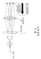
图1为第一种传统方法的分光装置的结构框图。Fig. 1 is a structural block diagram of a spectroscopic device of the first conventional method.
从光纤和准直器10输出的多波长光被偏振分束器/转换器单元11分束为p偏振光和s偏振光,并且可以通过波片将一个分束光的偏振状态转换为另一分束光的偏振状态。例如,当图1中的分光装置具有对于p偏振光最佳的工作结构时,通过偏振分束器/转换器单元11将s偏振光转换为p偏振光。通过这种方式,由棱镜对12使通过偏振分束器/转换器的光束的宽度扩大,并使其入射到会聚透镜13。由会聚透镜13会聚的光被MEMS反射镜阵列14反射,并被输入到分解透镜15。该分解透镜15例如通过p偏振光以及从s偏振光转换为p偏振光的光对衍射光栅16进行照射。通过衍射光栅16获得光的光谱。从图1中可以清楚地看到,为了接收两个分离的光束,衍射光栅16必须具有很大的面积。随着面积的增大,衍射光栅16的生产变得更加困难,产量也会降低。因此,如果要使用大面积的衍射光栅,则整个分光装置的价格将会很高。分光装置本身的尺寸也会变得很大,这与当前小尺寸和低价格装置的要求相悖。The multi-wavelength light output from the optical fiber and
图2A-2B和图3为说明第二种传统方法的示意图。2A-2B and FIG. 3 are schematic diagrams illustrating the second conventional method.
第二种方法是在专利文献1和其它文献中所述的方法。忽略了第一衍射光栅的角色散,并选择衍射光栅的参数,以使得可以在指定的波长处获得低偏振依赖性和高衍射效率。如图2A和图2B所示,为了对不足的角色散进行补偿,设置了两个(或者偶数个)衍射光栅,以使得它们的角色散相加。此外,为了防止在包含所指定波长的波长范围内发生PDL,在衍射光栅之间设置波片。通过使两个衍射光栅之间的偏振状态反转来消除PDL。这种方法使得能够获得低偏振依赖性、高衍射效率和高角色散。The second method is the method described in Patent Document 1 and other documents. The angular dispersion of the first diffraction grating is ignored, and the parameters of the diffraction grating are chosen such that low polarization dependence and high diffraction efficiency can be obtained at the specified wavelength. As shown in FIG. 2A and FIG. 2B , in order to compensate for insufficient angular dispersion, two (or an even number) diffraction gratings are set such that their angular dispersions are summed. Furthermore, in order to prevent PDL from occurring in the wavelength range including the specified wavelength, a wave plate is provided between the diffraction gratings. The PDL is eliminated by inverting the polarization state between the two diffraction gratings. This approach enables low polarization dependence, high diffraction efficiency and high angular dispersion.
如图2A所示,为了通过聚焦光学系统21对光(通过衍射光栅20获得了该光的光谱)进行会聚,并且该光适当地入射到光学接收器元件或者可移动反射器阵列22上,在分光分束之后会聚的光的空间间隔必须与光学接收器元件或者可移动反射阵列22的阵列间隔相对应。因此,当衍射光栅的角色散不足时,衍射光栅20与光学接收器元件或可移动反射器阵列22之间的间距必须更长。然而,这导致装置尺寸的增大。因此,如图2B所示,通过使用两个或者更多个衍射光栅20来获得大的角色散。通过这样做,可以减小衍射光栅20与光学接收器元件或可移动反射器阵列22之间的间距,使得整个装置能够保持得较小。此外,在第二种方法中,在衍射光栅20之间设置了波片23以减小偏振依赖性。As shown in FIG. 2A , in order to converge the light (the spectrum of which is obtained by the diffraction grating 20 ) by the focusing optics 21 , and for the light to be properly incident on the optical receiver element or the movable reflector array 22 , the The spatial spacing of the convergent light after beam splitting must correspond to the array spacing of the optical receiver elements or the movable reflective array 22 . Therefore, when the angular dispersion of the diffraction grating is insufficient, the spacing between the diffraction grating 20 and the optical receiver elements or movable reflector array 22 must be longer. However, this leads to an increase in the size of the device. Therefore, a large angular dispersion is obtained by using two or
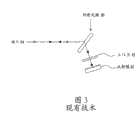
图3是专利文献1中所述的分光装置的基本结构示意图。在这种结构中,光穿过衍射光栅20两次来获得角色散,而不是穿过两个衍射光栅20。通过衍射光栅20来获得从端口24进入的光的光谱。经分光分束的光穿过1/4波片23,并由反射镜22反射。由反射镜22反射的光再一次穿过1/4波片23。这里,光穿过1/4波片两次,并且该光的偏振状态从p偏振光转换为s偏振光,或者从s偏振光转换为p偏振光。在处于偏振状态已转换的状态下,该光第二次穿过衍射光栅。由于光穿过衍射光栅20两次,所以角色散加倍;然而,在光第一次穿过衍射光栅20时偏振状态发生转换,并在第二次穿过衍射光栅20时再次发生转换。当光在偏振状态发生转换的情况下两次穿过同一衍射光栅20时,衍射光栅20的偏振特性被抵消。换言之,假设第一次对于p偏振的光产生的损耗是a,第二次对于s偏振的光产生的损耗是b,则光两次穿过衍射光栅20所导致的总损耗是a+b。另一方面,由穿过衍射光栅20两次且每一次都转换偏振状态的光(第一次为s偏振)导致的损耗是b+a。因此,可以获得下述的效果:在光两次穿过衍射光栅20之后,两种偏振分量产生相同的损耗。FIG. 3 is a schematic diagram of the basic structure of the spectroscopic device described in Patent Document 1. As shown in FIG. In this configuration, light passes through the diffraction grating 20 twice to obtain angular dispersion, instead of passing through two
图4为说明第三种传统方法的示意图。Fig. 4 is a schematic diagram illustrating a third conventional method.
在专利文献2和专利文献3中描述了第三种方法。与第二种方法相似,忽略了一个衍射光栅的角色散,并选择该衍射光栅的参数,以使得可以在指定的波长处获得低偏振依赖性和高衍射效率。为了对不足的角色散进行补偿,设置了两个(或者偶数个)衍射光栅,以使得它们的角色散相加。此时,这些衍射光栅被设置为使得它们的刻槽(groove)互相垂直。由于这些刻槽互相垂直,p偏振光和s偏振光的入射状态反转,所以可以获得与在衍射光栅之间设置波片时获得的效果相同的效果。这种方法使得能够获得低偏振依赖性、高衍射效率和高角色散(与第二种方法相比,这种方法的优点是不需要波片)。The third method is described in Patent Document 2 and Patent Document 3. Similar to the second method, the angular dispersion of one diffraction grating is ignored, and the parameters of this diffraction grating are chosen such that low polarization dependence and high diffraction efficiency can be obtained at a specified wavelength. In order to compensate for the insufficient angular dispersion, two (or an even number) diffraction gratings are arranged such that their angular dispersions add up. At this time, these diffraction gratings are arranged such that their grooves are perpendicular to each other. Since these grooves are perpendicular to each other, the incident states of p-polarized light and s-polarized light are reversed, so that the same effect as that obtained when a wave plate is provided between the diffraction gratings can be obtained. This approach enables low polarization dependence, high diffraction efficiency and high angular dispersion (compared to the second approach, which has the advantage of not requiring waveplates).
在图4中,从光纤25输入的光由准直透镜26准直,并通过第一衍射光栅27获得该光的光谱。经分光分束的光传播到第二衍射光栅28。第二衍射光栅的刻槽与第一衍射光栅27的刻槽正交。通过第二衍射光栅28沿与第一衍射光栅27正交的方向获得该光的光谱。通过第二衍射光栅28获得的分光分束光通过聚焦透镜29会聚到阵列元件30上。在这种情况下,由于第一衍射光栅27和第二衍射光栅28的角色散的方向彼此正交,所以角色散不是第一衍射光栅27和第二衍射光栅28两者的角色散的简单相加。因此,角色散变得小于该简单总和。In FIG. 4 , light input from an optical fiber 25 is collimated by a collimator lens 26 , and the spectrum of the light is obtained through a first diffraction grating 27 . The spectroscopically split light travels to the
[专利文献1][Patent Document 1]
美国专利No.6765724US Patent No.6765724
[专利文献2][Patent Document 2]
日本专利申请公报No.H02-61529Japanese Patent Application Publication No.H02-61529
[专利文献3][Patent Document 3]
日本专利申请公报No.2001-13006Japanese Patent Application Publication No.2001-13006
[非专利文献1][Non-Patent Document 1]
D.M.Marom″Wavelength Selective lxK Switching System″Optical MEMS 2003 pp.43-44D.M.Marom″Wavelength Selective lxK Switching System″Optical MEMS 2003 pp.43-44
然而,上述三种方法具有下列问题。However, the above three methods have the following problems.
在第一种方法中,由于图1中的偏振分束器,而使得在该偏振分束器后面的元件(包括衍射光栅在内)的有效面积必须是两倍大,结果使光学元件的尺寸增大,导致成本增加。具体地,如果衍射光栅的面积加倍,则产量的降低通常会超过两倍,并且成本通常也会增加两倍。In the first method, due to the polarizing beam splitter in Fig. 1, the effective area of the elements behind the polarizing beam splitter (including the diffraction grating) must be twice as large, resulting in the size of the optical element increase, leading to an increase in cost. Specifically, if the area of the diffraction grating is doubled, the reduction in yield is typically more than doubled, and the cost is also typically tripled.
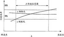
图5A-5B是表示第二种方法中的衍射效率的示意图。第二种方法使用具有相同特性的衍射光栅。因此,当使p偏振光的衍射效率与s偏振光的衍射效率相同的波长不具备在工作波长范围的中心的任意一侧对称的特性时,在工作波长范围内,整个插入损耗产生波长依赖性。对称的衍射效率和角色散特性通常还是很难获得,其仅能对工作波长实现。换言之,如果衍射光栅具有图5A的特性,则在图5B中示出了s偏振光和p偏振光转换和叠加的特征。在这种情况下,衍射效率在工作波长范围内仍具有波长依赖性。5A-5B are graphs showing diffraction efficiency in the second method. The second method uses a diffraction grating with the same properties. Therefore, when the wavelength at which the diffraction efficiency of p-polarized light is the same as that of s-polarized light does not have the characteristic of being symmetrical on either side of the center of the operating wavelength range, the entire insertion loss is wavelength-dependent in the operating wavelength range . Symmetrical diffraction efficiency and angular dispersion properties are generally still difficult to obtain, which can only be achieved for the operating wavelength. In other words, if the diffraction grating has the characteristics of FIG. 5A, the characteristics of conversion and superposition of s-polarized light and p-polarized light are shown in FIG. 5B. In this case, the diffraction efficiency remains wavelength-dependent in the operating wavelength range.
除了第二种方法的问题之外,第三种方法还具有下述的问题,例如,设备内部的光学结构是三维的(阵列元件相对于衍射光栅的刻槽倾斜45度),并且整个角色散大约为第二种方法的
发明内容Contents of the invention
本发明的一个目的在于提供一种多波长分光装置,该多波长分光装置可以低成本地实现,并且可以通过实现低偏振依赖性、高衍射效率和高角色散,通过保持光学元件的尺寸,以及通过控制组件数量,来控制整个衍射效率的波长依赖性,以消除偏振依赖性。An object of the present invention is to provide a multi-wavelength spectroscopic device that can be realized at low cost, and can achieve low polarization dependence, high diffraction efficiency, and high angular dispersion, by maintaining the size of the optical elements, and By controlling the number of components, the wavelength dependence of the overall diffraction efficiency can be controlled to eliminate the polarization dependence.
根据本发明的多波长分光装置包括:分光单元,该分光单元具有至少两个衍射光栅,该分光单元被设置为使得这些衍射光栅的刻槽平行,并且使得一些衍射光栅的波长特性为:p偏振光和s偏振光的衍射效率相等处的波长位于工作波长范围内的短波长端附近,另外使得其它衍射光栅的波长特性为:p偏振光和s偏振光的衍射效率相等处的波长位于工作波长范围内的长波长端附近。The multi-wavelength spectroscopic device according to the present invention includes: a spectroscopic unit having at least two diffraction gratings, the spectroscopic unit is arranged so that the grooves of these diffractive gratings are parallel, and the wavelength characteristics of some diffractive gratings are: p-polarization The wavelength at which the diffraction efficiencies of light and s-polarized light are equal is located near the short-wavelength end of the working wavelength range, and the wavelength characteristics of other diffraction gratings are: the wavelength at which the diffraction efficiencies of p-polarized light and s-polarized light are equal is at the working wavelength near the long wavelength end of the range.
根据本发明的多波长分光装置,能够以低成本实现尺寸小并且具有良好光学特性(例如,低偏振依赖性和高衍射效率)的多波长同时控制设备。According to the multi-wavelength spectroscopic device of the present invention, a multi-wavelength simultaneous control device that is small in size and has good optical characteristics (for example, low polarization dependence and high diffraction efficiency) can be realized at low cost.
本发明还涉及一种光学设备,其包括:光学输入端口;根据上述多波长分光装置,用于对来自所述输入端口的光进行分光分束;聚焦光学系统,用于会聚所述分光分束光;以及在所述聚焦光学系统的焦点位置附近沿一维设置的光学元件。The present invention also relates to an optical device, which includes: an optical input port; according to the above-mentioned multi-wavelength splitting device, used for splitting and splitting the light from the input port; focusing optical system, used for converging the split beams light; and an optical element disposed along one dimension near a focal position of the focusing optical system.
附图说明Description of drawings
图1是表示第一种传统方法的分光装置的结构的框图。FIG. 1 is a block diagram showing the configuration of a spectroscopic device of a first conventional method.
图2A-2B为说明第二种传统方法的示意图(1)。2A-2B are schematic diagrams (1) illustrating the second conventional method.
图3为说明第二种传统方法的示意图(2)。Fig. 3 is a schematic diagram (2) illustrating the second conventional method.
图4为说明第三种传统方法的示意图。Fig. 4 is a schematic diagram illustrating a third conventional method.
图5A-5B是表示第二种方法的衍射效率的概况的示意图。5A-5B are graphs showing the outline of the diffraction efficiency of the second method.
图6A-6C是说明本发明实施例的第一原理的示意图。6A-6C are schematic diagrams illustrating a first principle of an embodiment of the present invention.
图7A-7C是说明本发明实施例的第二原理的示意图。7A-7C are schematic diagrams illustrating a second principle of an embodiment of the present invention.
图8是表示衍射光栅的衍射效率特性的示例的示意图。FIG. 8 is a schematic diagram showing an example of diffraction efficiency characteristics of a diffraction grating.
图9是描述使用根据本发明实施例的分光装置的设备示例的示意图。Fig. 9 is a schematic diagram describing an example of an apparatus using a spectroscopic device according to an embodiment of the present invention.
图10是表示应用于波长选择开关的本发明实施例的具体结构示例的示意图。Fig. 10 is a diagram showing a specific structural example of an embodiment of the present invention applied to a wavelength selective switch.
图11是说明应用了本发明实施例的光学器件的详细点的示意图。Fig. 11 is a schematic diagram illustrating detailed points of an optical device to which an embodiment of the present invention is applied.
具体实施方式Detailed ways
本发明实施例的多波长分光装置采用了多个衍射光栅,其中,对于至少一对光栅,存在使p偏振光和s偏振光的衍射效率相等并且分别位于工作波长范围的各个端部附近的波长,该多个衍射光栅被设置为使得这些衍射光栅的刻槽大致平行;或者采用下述的多个衍射光栅,对于该多个衍射光栅,p偏振光和s偏振光的最大/最小衍射效率在工作波长范围内反转,该多个衍射光栅被设置为使得这些衍射光栅的刻槽大致平行。The multi-wavelength spectroscopic device of the embodiment of the present invention adopts a plurality of diffraction gratings, wherein, for at least one pair of gratings, there are wavelengths that make the diffraction efficiencies of p-polarized light and s-polarized light equal and are respectively located near the respective ends of the working wavelength range , the plurality of diffraction gratings are arranged so that the grooves of these diffraction gratings are approximately parallel; or adopt the following plurality of diffraction gratings, for the plurality of diffraction gratings, the maximum/minimum diffraction efficiencies of p-polarized light and s-polarized light are at Inverted within the working wavelength range, the plurality of diffraction gratings are arranged such that the grooves of these diffraction gratings are approximately parallel.
图6A-6C是说明本发明实施例的第一原理的示意图。6A-6C are schematic diagrams illustrating a first principle of an embodiment of the present invention.
在图6A-6C的示例中,如图6A所示,第一衍射光栅是下述的衍射光栅,该衍射光栅被设计为使得p偏振光和s偏振光的衍射效率共享工作波长范围的短波长侧的一个相同的点;如图6B所示,第二衍射光栅是下述的衍射光栅,该衍射光栅被设计为使得p偏振光和s偏振光的衍射效率共享长波长侧的相同点。如图6C所示,在光通过第一衍射光栅和第二衍射光栅之后,对于各种波长的光的各种偏振状态的衍射效率为第一衍射效率和第二衍射效率之积。当在第一衍射光栅中和第二衍射光栅中两种偏振状态的衍射效率之间的差异的最大量相等时,可以获得与在任一衍射光栅中使用波片时所获得的特性相同的效果。如图6C所示,根据上述结构,对于s偏振光和p偏振光,两个衍射光栅的组合衍射效率表现出窄的变化范围,从而使得衍射效率的变化范围落入工作波长范围内的指定范围内。通过将两个衍射光栅设置为使得刻槽大致平行,使发散方向基本相同,由此使两个衍射光栅的角色散相加。结果,可以增大角色散。In the example of FIGS. 6A-6C , as shown in FIG. 6A , the first diffraction grating is a diffraction grating designed such that the diffraction efficiencies of p-polarized light and s-polarized light share the short wavelength of the operating wavelength range A same point on the side; as shown in FIG. 6B, the second diffraction grating is a diffraction grating designed so that the diffraction efficiency of p-polarized light and s-polarized light shares the same point on the long-wavelength side. As shown in FIG. 6C , after light passes through the first diffraction grating and the second diffraction grating, the diffraction efficiencies for various polarization states of light of various wavelengths are the product of the first diffraction efficiency and the second diffraction efficiency. When the maximum amount of the difference between the diffraction efficiencies of the two polarization states is equal in the first diffraction grating and in the second diffraction grating, the same effect as that obtained when a wave plate is used in either diffraction grating can be obtained. As shown in Figure 6C, according to the above structure, the combined diffraction efficiency of the two diffraction gratings exhibits a narrow variation range for s-polarized light and p-polarized light, so that the variation range of the diffraction efficiency falls within the specified range within the operating wavelength range Inside. By arranging the two diffraction gratings so that the grooves are approximately parallel, the directions of divergence are made substantially the same, thereby adding the angular dispersion of the two diffraction gratings. As a result, angular dispersion can be increased.
图7A-7C是本发明实施例的第二原理的示意图。7A-7C are schematic diagrams of the second principle of the embodiment of the present invention.
在图7A-7C的示例中,图7A中的第一衍射光栅和图7B中的第二衍射光栅是下述的衍射光栅,这些衍射光栅被设计为使得使p偏振光和s偏振光的偏振效率相同的波长大致相同,并且对于p偏振光(或s偏振光)的衍射效率反转。如图7C所示,各种偏振状态在各个波长处的衍射效率为第一衍射光栅和第二衍射光栅的衍射效率之积。图6A-6C的示例之间的差别在于使p偏振光和s偏振光的衍射效率相等的波长的相对位置。这表示,当衍射效率的设计受到限制或者由于制造公差而导致特性发生变化时,可以通过图6A-6C中的结构或者通过图7A-7C中的结构,来实现降低偏振依赖性的效果,因此,也可以实现降低用于获得所需特性的成本的效果。In the example of FIGS. 7A-7C , the first diffraction grating in FIG. 7A and the second diffraction grating in FIG. 7B are diffraction gratings designed such that the polarization of p-polarized light and s-polarized light Wavelengths with the same efficiency are approximately the same, and the diffraction efficiency for p-polarized light (or s-polarized light) is reversed. As shown in FIG. 7C , the diffraction efficiency of each polarization state at each wavelength is the product of the diffraction efficiencies of the first diffraction grating and the second diffraction grating. The difference between the examples of FIGS. 6A-6C is the relative position of the wavelengths that equate the diffraction efficiencies of p-polarized and s-polarized light. This means that when the design of the diffraction efficiency is limited or the characteristics change due to manufacturing tolerances, the effect of reducing the polarization dependence can be achieved by the structures in Figures 6A-6C or by the structures in Figures 7A-7C, so , can also achieve the effect of reducing the cost for obtaining desired characteristics.
在本发明实施例中使用的衍射光栅的特性可以通过对第一衍射光栅的光栅形状等进行精细调整来获得。然而,涉及衍射光栅的衍射效率的设计通常并不简单,因此通过使用模拟来进行设计。在Applied OpticsVol.16,No.10,p.2711、Vol.18,No.13,p.2262以及Vol.37,No.25,p.5823及其它文献中公开了反射型光栅的设计示例。在US6765724B1、日本专利申请特开公报No.2004-206039以及其他文献中公开了透射型光栅的设计示例。The characteristics of the diffraction grating used in the embodiment of the present invention can be obtained by finely adjusting the grating shape and the like of the first diffraction grating. However, the design involving the diffraction efficiency of the diffraction grating is generally not simple, and thus the design is performed by using simulation. Design examples of reflective gratings are disclosed in Applied Optics Vol.16, No.10, p.2711, Vol.18, No.13, p.2262 and Vol.37, No.25, p.5823, and others. Design examples of transmission type gratings are disclosed in US6765724B1, Japanese Patent Application Laid-Open Publication No. 2004-206039, and other documents.
图8是表示衍射光栅的衍射效率特性的示例的示意图。FIG. 8 is a schematic diagram showing an example of diffraction efficiency characteristics of a diffraction grating.
图8表示对于各个λ/D值的衍射效率,其中λ为工作波长,D为衍射光栅的栅距。在设计过程中,首先,设定工作波长范围。然后,通过调整栅距D来调整衍射光栅,以使得第一和第二衍射光栅在工作波长范围内具有如图6A-6C和图7A-7C所示的衍射效率特性。第一衍射光栅和第二衍射光栅中的不同栅距提供了图6A-6C和图7A-7C所示的特性。Fig. 8 shows the diffraction efficiency for various values of λ/D, where λ is the operating wavelength and D is the pitch of the diffraction grating. In the design process, first, set the operating wavelength range. Then, the diffraction grating is adjusted by adjusting the pitch D, so that the first and second diffraction gratings have the diffraction efficiency characteristics shown in FIGS. 6A-6C and FIGS. 7A-7C within the working wavelength range. The different pitches in the first and second diffraction gratings provide the characteristics shown in FIGS. 6A-6C and 7A-7C.
在上述实施例中,说明了使用两个衍射光栅的情况;然而,也可以组合三个或者更多个衍射光栅。换言之,只要将衍射光栅组合为使得在工作波长范围内衍射效率特性的变化相互消除,就可以使用任意数量的衍射光栅。In the above-described embodiments, the case of using two diffraction gratings has been described; however, three or more diffraction gratings may also be combined. In other words, any number of diffraction gratings may be used as long as the diffraction gratings are combined such that variations in diffraction efficiency characteristics within the operating wavelength range cancel each other out.
与现有技术相比,本发明的实施例还在多波长分光装置的整个工作波长范围内具有更小的效率变化,此外,可以通过采用波片来减小波长依赖性。在使用波片时,该结构应该包括偶数个衍射光栅,并且光应该恰好在穿过波片之前或之后通过衍射光栅。该波片具有实现p偏振光和s偏振光的转换,以及使p偏振光的特性和s偏振光的特性均衡的效果。该波片例如为1/4波片。Compared with the prior art, the embodiment of the present invention also has smaller efficiency variation in the entire working wavelength range of the multi-wavelength spectroscopic device, and in addition, wavelength dependence can be reduced by using a wave plate. When using a wave plate, the structure should include an even number of diffraction gratings, and the light should pass through the diffraction gratings just before or after passing through the wave plate. The wave plate has the effect of realizing the conversion of p-polarized light and s-polarized light, and balancing the characteristics of p-polarized light and s-polarized light. The wave plate is, for example, a 1/4 wave plate.
图9是描述使用根据本发明实施例的分光装置的设备示例的示意图。Fig. 9 is a schematic diagram describing an example of an apparatus using a spectroscopic device according to an embodiment of the present invention.
本结构的设备被称为波长选择开关,并且作为最小的组件包括:分光单元34,用于获得波长复用光信号的光谱;输入/输出光学系统(输入光学系统和输出光学系统),其具有输入/输出端口等(光纤31,准直器32和光学扩展系统33);光学聚焦系统35;根据波长设置的MEMS反射镜阵列或光电二极管阵列36。根据本发明的实施例,分光单元34应该包括两个或者更多个衍射光栅。通过准直器32使来自光纤31的com的光输入成为准直光束,并通过光学扩展系统33使其光束宽度增大。通过分光单元34的衍射光栅来获得该光束的光谱,并且通过光学聚焦系统35的聚焦透镜将该分光分束光会聚到MEMS反射镜阵列或光电二极管阵列36的元件上。当光会聚到MEMS反射镜阵列上时,所会聚的光被反射,按照光学聚焦系统35、分光单元34、光学扩展系统33、准直器32的顺序传播,并连接到光纤31中的任何一个,以进行输出。当光被会聚到光电二极管上时,通过光电二极管将光转换为电信号,并且不反射。The device of this structure is called a wavelength selective switch, and includes as minimum components: a light splitting unit 34 for obtaining a spectrum of a wavelength-multiplexed optical signal; an input/output optical system (an input optical system and an output optical system) having Input/output ports etc. (optical fiber 31, collimator 32 and optical extension system 33); optical focusing system 35; MEMS mirror array or photodiode array 36 set according to wavelength. According to an embodiment of the present invention, the light splitting unit 34 should include two or more diffraction gratings. The light input from the com of the optical fiber 31 is turned into a collimated beam by the collimator 32 , and the width of the beam is enlarged by the optical expansion system 33 . The spectrum of the light beam is obtained by the diffraction grating of the light splitting unit 34 , and the split beam is converged onto elements of the MEMS mirror array or photodiode array 36 by the focusing lens of the optical focusing system 35 . When the light converges onto the MEMS mirror array, the converged light is reflected, propagates in the order of the optical focusing system 35, the light splitting unit 34, the optical expansion system 33, and the collimator 32, and is connected to any one of the optical fibers 31 , for output. When light is condensed onto a photodiode, it is converted into an electrical signal by the photodiode and is not reflected.
图9所示的分光元件是透射型衍射光栅的示例,在沿不同的方向对将各个波长进行衍射之后,该分光元件输出所输入光束的多个波长分量。各个可移动反射器(MEMS反射镜阵列)位于其沿波长的衍射方向与波长相对应的位置。通过沿着端口的排列方向改变该可移动反射器的角度,可以使从输入端口输入的波长分布到输出端口中的任何一个上。此外,在这种结构中,可以在一对透射型衍射光栅42之间设置1/4波片49。通过这样做,进一步减小了光学设备的偏振依赖性,从而产生具有更高性能的光学设备。该波片可以设置在MEMS反射镜阵列或光电二极管36之前,即在孔径48的第二偏转反射镜45侧,而不是在衍射光栅之间。The spectroscopic element shown in FIG. 9 is an example of a transmission type diffraction grating, which outputs a plurality of wavelength components of an input light beam after diffracting respective wavelengths in different directions. Each movable reflector (MEMS mirror array) is located at a position where its diffraction direction along the wavelength corresponds to the wavelength. By changing the angle of the movable reflector along the arrangement direction of the ports, the wavelength input from the input port can be distributed to any one of the output ports. Furthermore, in this structure, a 1/4 wave plate 49 may be provided between a pair of transmission type diffraction gratings 42 . By doing so, the polarization dependence of the optical device is further reduced, resulting in an optical device with higher performance. The waveplate may be placed before the MEMS mirror array or photodiode 36, ie on the second deflection mirror 45 side of the aperture 48, rather than between the diffraction gratings.
图10是表示在将本发明的实施例应用于波长选择开关时的具体结构示例的示意图。FIG. 10 is a schematic diagram showing a specific structural example when an embodiment of the present invention is applied to a wavelength selective switch.
在图10中,光如箭头所示传播。首先,光从准直器阵列40进入,并通过扩束器(扩展光学系统)41。通过扩束器41扩大光束的宽度。然后,通过穿过一对透射型衍射光栅42来获得该光的光谱。根据本发明的实施例,该对透射型衍射光栅42应该包括两个或者更多个衍射光栅。图10示出了使用两个衍射光栅的示例。该对衍射光栅42的光输出被第一折返反射镜(folding mirror)43反射,并且入射到聚焦透镜44上。通过聚焦透镜44会聚的光的传播方向被第二折返反射镜45改变,并被导向MEMS反射镜阵列46所在的位置。MEMS反射镜阵列46通常被构造为一个封装,并且固定在设置在壳体47中的孔径48处。In Fig. 10, light propagates as indicated by arrows. First, light enters from a
根据本发明的实施例,图10中的波长选择开关的尺寸小,并具有良好的光学特性(在宽波长范围内的低偏振依赖性和高衍射效率)。According to an embodiment of the present invention, the wavelength selective switch in FIG. 10 is small in size and has good optical properties (low polarization dependence and high diffraction efficiency over a wide wavelength range).
图11是说明应用了本发明实施例的光学设备的详细点的示意图。Fig. 11 is a schematic diagram illustrating detailed points of an optical device to which an embodiment of the present invention is applied.
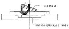
出于对产品的考虑,希望MEMS反射镜阵列或光电二极管阵列51是单独的封装。然而,在本结构中,光学输入以相对于封装窗口50大致垂直的角度进入,并且封装窗口50处的反射损耗是有限的。结果,在输出端口产生光学重像。For product considerations, it is desirable that the MEMS mirror array or photodiode array 51 be a separate package. However, in the present configuration, the optical input enters at a substantially perpendicular angle relative to the
在本结构中,当MEMS反射镜阵列或光电二极管阵列51位于单独的封装中时,如图11所示,可以通过倾斜封装窗口50来防止光学重像的产生。换言之,如果不倾斜封装窗口50,则光由封装窗口50反射,从而产生重像。当封装窗口倾斜时,由封装窗口50反射的光偏离光路,从而光学重像不会到达输出端口。通过这样做,可以提高使用本发明实施例的多波长分光装置的光学设备的性能。In this structure, when the MEMS mirror array or photodiode array 51 is located in a separate package, as shown in FIG. 11 , optical ghosting can be prevented by tilting the
此外,在波长选择开关的该结构中,由于光通过同一衍射光栅两次,所以不仅可以通过在衍射光栅之间设置波片,而且可以通过在可移动反射器阵列之前设置波片来获得相同的效果。然而,如图11所示,在设置波片时,为了避免由波片反射的光作为输出端口处的光学重像出现的问题,最好如在封装窗口50的情况下那样使波片倾斜。应当注意,该波片例如为1/4波片。Furthermore, in this structure of the wavelength selective switch, since the light passes through the same diffraction grating twice, the same can be obtained not only by disposing the wave plate between the diffraction gratings but also by disposing the wave plate before the movable reflector array. Effect. However, as shown in FIG. 11 , when setting the wave plate, it is preferable to tilt the wave plate as in the case of the
如上所述,在本发明的实施例中,分光单元具有使用多个衍射光栅的结构,其中至少一对光栅具有下述的波长,该波长使p偏振光和s偏振光的衍射效率相等并且位于各个光栅的工作波长范围的不同端部附近,该多个衍射光栅被设置为使得这些衍射光栅的刻槽大致平行。或者该单元具有使用多个衍射光栅的结构,其中p偏振光和s偏振光的最大/最小衍射效率在工作波长范围内反转,该多个衍射光栅被设置为使得这些衍射光栅的刻槽大致平行。在存在偶数个衍射光栅的结构中,通过在至少一对衍射光栅之间设置用于转换p偏振光和s偏振光的波片,可以提高分光装置的性能。当在光通信中使用本发明实施例的分光装置时,希望选择下述的范围作为衍射光栅的工作波长范围:C波段1520-1567nm、L波段1567-1618nm、或者包括C波段和L波段的1520-1618nm中的各个范围的±10%的范围。As described above, in an embodiment of the present invention, the spectroscopic unit has a structure using a plurality of diffraction gratings, wherein at least one pair of gratings has wavelengths that equalize the diffraction efficiencies of p-polarized light and s-polarized light and are located at Near different ends of the operating wavelength range of the respective gratings, the plurality of diffraction gratings are arranged such that grooves of the diffraction gratings are substantially parallel. Or the unit has a structure using a plurality of diffraction gratings in which the maximum/minimum diffraction efficiencies of p-polarized light and s-polarized light are reversed in the operating wavelength range, the plurality of diffraction gratings being arranged such that the grooves of these diffraction gratings are approximately parallel. In a structure in which there is an even number of diffraction gratings, the performance of the spectroscopic device can be improved by disposing a wave plate for converting p-polarized light and s-polarized light between at least one pair of diffraction gratings. When using the spectroscopic device of the embodiment of the present invention in optical communication, it is desirable to select the following range as the working wavelength range of the diffraction grating: C-band 1520-1567nm, L-band 1567-1618nm, or 1520nm including C-band and L-band The range of ±10% of each range in -1618nm.
此外,当构造包括MEMS反射镜阵列或光电二极管的光学设备时,希望构成MEMS反射镜阵列或光电二极管的封装的封装窗口相对于光路倾斜。经验证明该倾斜的角度应该为5度或更大。当在衍射光栅之间或在MEMS反射镜阵列或光电二极管之前设置波片时,该波片也应该是倾斜的。根据经验,将该波片的倾斜角度确定为5度或更大。Furthermore, when constructing an optical device including a MEMS mirror array or photodiode, it is desirable that the package window of the package constituting the MEMS mirror array or photodiode be inclined with respect to the optical path. Experience has shown that the angle of inclination should be 5 degrees or more. When the waveplate is placed between the diffraction gratings or before the MEMS mirror array or photodiode, the waveplate should also be tilted. According to experience, the tilt angle of the wave plate is determined to be 5 degrees or more.
如前所述,本发明实施例中的多波长分光装置和使用该装置的设备尺寸小,并具有良好的光学特性(在宽波长范围内的低偏振依赖性和高衍射效率)。As described above, the multi-wavelength spectroscopic device in the embodiment of the present invention and the equipment using the device are small in size and have good optical characteristics (low polarization dependence and high diffraction efficiency in a wide wavelength range).
Claims (10)
Applications Claiming Priority (2)
| Application Number | Priority Date | Filing Date | Title |
|---|---|---|---|
| JP2005359307 | 2005-12-13 | ||
| JP2005359307AJP4908838B2 (en) | 2005-12-13 | 2005-12-13 | Multi-wavelength spectrometer |
Publications (2)
| Publication Number | Publication Date |
|---|---|
| CN1982944A CN1982944A (en) | 2007-06-20 |
| CN100412611Ctrue CN100412611C (en) | 2008-08-20 |
Family
ID=37813829
Family Applications (1)
| Application Number | Title | Priority Date | Filing Date |
|---|---|---|---|
| CNB2006100764398AActiveCN100412611C (en) | 2005-12-13 | 2006-04-20 | Multi-wavelength spectroscopic device |
Country Status (4)
| Country | Link |
|---|---|
| US (1) | US7359051B2 (en) |
| EP (1) | EP1798534B1 (en) |
| JP (1) | JP4908838B2 (en) |
| CN (1) | CN100412611C (en) |
Cited By (1)
| Publication number | Priority date | Publication date | Assignee | Title |
|---|---|---|---|---|
| CN103676010A (en)* | 2012-09-13 | 2014-03-26 | 住友电气工业株式会社 | Wavelength selective switch |
Families Citing this family (21)
| Publication number | Priority date | Publication date | Assignee | Title |
|---|---|---|---|---|
| US8164747B2 (en)* | 2006-12-14 | 2012-04-24 | ASD, Inc | Apparatus, system and method for optical spectroscopic measurements |
| US8284489B2 (en)* | 2007-09-11 | 2012-10-09 | Aegis Lightwave, Inc. | Spectrally adjustable filter |
| CN101809661B (en)* | 2007-09-27 | 2012-07-11 | 柯尼卡美能达精密光学株式会社 | Objective lens for optical pickup devices and optical pickup device |
| JP4453785B2 (en)* | 2007-10-11 | 2010-04-21 | コニカミノルタオプト株式会社 | Objective lens for optical pickup device and optical pickup device |
| US20090273840A1 (en)* | 2008-05-02 | 2009-11-05 | Mclaughlin Sheldon | Wavelength dispersing device |
| WO2010096081A1 (en)* | 2008-09-04 | 2010-08-26 | University Of Florida Research Foundation, Inc. | Mems-based ftir spectrometer |
| JP5182049B2 (en) | 2008-12-09 | 2013-04-10 | 富士通株式会社 | Polarization conversion device and polarization multiplexing modulator |
| CA2776235C (en) | 2009-10-01 | 2018-03-13 | Tornado Medical Systems, Inc. | Optical slicer for improving the spectral resolution of a dispersive spectrograph |
| US8526005B1 (en) | 2010-01-21 | 2013-09-03 | Lockheed Martin Corporation | System and method for calibrating optical measurement systems that utilize polarization diversity |
| JP2011179979A (en)* | 2010-03-01 | 2011-09-15 | Furukawa Electric Co Ltd:The | Double-path monochromater, wavelength selection optical switch, and optical channel monitor |
| US8917390B2 (en)* | 2011-06-24 | 2014-12-23 | Tornado Spectral Systems Inc. | Spectrograph with anamorphic beam expansion |
| CN102375245B (en)* | 2011-11-16 | 2013-03-27 | 合肥工业大学 | Light splitting system for naked eye three-dimensional display |
| JP6182988B2 (en) | 2013-06-12 | 2017-08-23 | 住友電気工業株式会社 | Spectroscopic device and wavelength selective switch |
| JP6278180B2 (en)* | 2014-02-05 | 2018-02-14 | 株式会社リコー | Optical scanning device, image display device, and moving body |
| JP6344068B2 (en)* | 2014-06-05 | 2018-06-20 | 住友電気工業株式会社 | Wavelength selective switch |
| JP6349980B2 (en)* | 2014-06-05 | 2018-07-04 | 住友電気工業株式会社 | Wavelength selective switch |
| EP3248050B1 (en) | 2015-01-21 | 2020-06-03 | Tornado Spectral Systems, Inc. | Hybrid image-pupil optical reformatter |
| CN111061015A (en)* | 2019-12-27 | 2020-04-24 | 武汉邮电科学研究院有限公司 | Wavelength selective switch with double gratings and design method thereof |
| DE102020202819A1 (en)* | 2020-03-05 | 2021-09-09 | Robert Bosch Gesellschaft mit beschränkter Haftung | LiDAR device |
| CN112394436B (en)* | 2020-11-25 | 2021-07-06 | 中国科学院上海光学精密机械研究所 | Asymmetric Structure All-Dielectric Reflective Beam Combining Grating in 1064 nm Band |
| US20220271859A1 (en)* | 2021-02-19 | 2022-08-25 | Nokia Solutions And Networks Oy | Wavelength selective switch with direct grating interface |
Citations (5)
| Publication number | Priority date | Publication date | Assignee | Title |
|---|---|---|---|---|
| US5559597A (en)* | 1993-04-21 | 1996-09-24 | Kaiser Optical Systems, Inc. | Spectrograph with multiplexing of different wavelength regions onto a single opto-electric detector array |
| CN1402022A (en)* | 2001-08-09 | 2003-03-12 | 阿尔卑斯电气株式会社 | Diffraction grating member |
| US20030170024A1 (en)* | 2001-09-05 | 2003-09-11 | Kimihiko Nishioka | Deformable mirror and optical device using the same |
| US20040033010A1 (en)* | 2002-06-12 | 2004-02-19 | Mcguire James P. | Wavelength selective optical switch |
| US6765724B1 (en)* | 2001-01-16 | 2004-07-20 | Holotek, Llc | Diffraction grating-based wavelength selection unit having improved polarization dependent performance |
Family Cites Families (14)
| Publication number | Priority date | Publication date | Assignee | Title |
|---|---|---|---|---|
| JPS6192835A (en)* | 1984-10-13 | 1986-05-10 | Hitachi Chem Co Ltd | Lamination of composite material |
| JP2550651B2 (en)* | 1988-03-28 | 1996-11-06 | 株式会社島津製作所 | Double monochromator |
| JP2755958B2 (en)* | 1988-08-29 | 1998-05-25 | アンリツ株式会社 | Double grating spectrometer |
| JPH02159528A (en)* | 1988-12-12 | 1990-06-19 | Ando Electric Co Ltd | Two-stage type spectroscope |
| US6263127B1 (en)* | 1999-05-13 | 2001-07-17 | Lucent Technologies Inc. | Free-space/arrayed-waveguide router |
| JP2001013006A (en) | 1999-06-30 | 2001-01-19 | Asahi Glass Co Ltd | Spectrometer |
| US6487019B2 (en)* | 2000-03-27 | 2002-11-26 | Chromaplex, Inc. | Optical diffraction grating structure with reduced polarization sensitivity |
| CA2441934C (en)* | 2001-03-19 | 2009-05-26 | Capella Photonics, Inc. | Reconfiguration optical add-drop multiplexers |
| AU2002367061A1 (en) | 2001-12-21 | 2003-07-30 | Polychromix Corporation | Method and apparatus providing reduced polarization-dependent loss |
| JP2004206039A (en) | 2002-11-01 | 2004-07-22 | Sumitomo Electric Ind Ltd | Transmission type diffractive optical element |
| JP2004240215A (en)* | 2003-02-06 | 2004-08-26 | Sumitomo Electric Ind Ltd | Optical communication device and optical communication system |
| EP2214037B1 (en)* | 2003-02-18 | 2012-11-14 | Sumitomo Electric Industries, Ltd. | Diffraction grating element, and production method of diffraction grating element |
| JP4500720B2 (en)* | 2005-03-29 | 2010-07-14 | 富士通株式会社 | Light switch |
| JP2007010966A (en)* | 2005-06-30 | 2007-01-18 | Olympus Corp | Optical switch apparatus |
- 2005
- 2005-12-13JPJP2005359307Apatent/JP4908838B2/enactiveActive
- 2006
- 2006-03-30EPEP06006711.3Apatent/EP1798534B1/enactiveActive
- 2006-03-30USUS11/278,037patent/US7359051B2/enactiveActive
- 2006-04-20CNCNB2006100764398Apatent/CN100412611C/enactiveActive
Patent Citations (5)
| Publication number | Priority date | Publication date | Assignee | Title |
|---|---|---|---|---|
| US5559597A (en)* | 1993-04-21 | 1996-09-24 | Kaiser Optical Systems, Inc. | Spectrograph with multiplexing of different wavelength regions onto a single opto-electric detector array |
| US6765724B1 (en)* | 2001-01-16 | 2004-07-20 | Holotek, Llc | Diffraction grating-based wavelength selection unit having improved polarization dependent performance |
| CN1402022A (en)* | 2001-08-09 | 2003-03-12 | 阿尔卑斯电气株式会社 | Diffraction grating member |
| US20030170024A1 (en)* | 2001-09-05 | 2003-09-11 | Kimihiko Nishioka | Deformable mirror and optical device using the same |
| US20040033010A1 (en)* | 2002-06-12 | 2004-02-19 | Mcguire James P. | Wavelength selective optical switch |
Cited By (1)
| Publication number | Priority date | Publication date | Assignee | Title |
|---|---|---|---|---|
| CN103676010A (en)* | 2012-09-13 | 2014-03-26 | 住友电气工业株式会社 | Wavelength selective switch |
Also Published As
| Publication number | Publication date |
|---|---|
| JP4908838B2 (en) | 2012-04-04 |
| CN1982944A (en) | 2007-06-20 |
| EP1798534A1 (en) | 2007-06-20 |
| EP1798534B1 (en) | 2018-08-15 |
| JP2007163780A (en) | 2007-06-28 |
| US20070132993A1 (en) | 2007-06-14 |
| US7359051B2 (en) | 2008-04-15 |
Similar Documents
| Publication | Publication Date | Title |
|---|---|---|
| CN100412611C (en) | Multi-wavelength spectroscopic device | |
| JP5726407B2 (en) | Wavelength selective switch with characteristic operating surface | |
| US7263254B2 (en) | Optical switch and control method therefor | |
| US8811823B2 (en) | Dynamic optical devices | |
| US8391654B2 (en) | Wavelength selection switch | |
| JP2008541187A (en) | Monopolar optical wavelength selector | |
| US7054561B2 (en) | Reduction of polarization-dependent loss from grating used in double-pass configuration | |
| US7221452B2 (en) | Tunable optical filter, optical apparatus for use therewith and method utilizing same | |
| US7558447B2 (en) | Single-pole optical wavelength selector | |
| JPWO2018167975A1 (en) | Laser oscillator | |
| JP2003114402A (en) | Optical multiplexer / demultiplexer and adjustment method thereof | |
| US20130258470A1 (en) | Reduction of polarization-dependent loss in double-pass grating configurations | |
| JP2014056004A (en) | Wavelength selection optical switch device | |
| US20120224181A1 (en) | Wide-Band/High-Resolution Tunable Spectral Filter | |
| JP6117158B2 (en) | Optical operation device and control method thereof | |
| JP4407382B2 (en) | Optical filter device | |
| WO2014141469A1 (en) | Wavelength selection switch | |
| JP3460960B2 (en) | Broadband spatial light phase modulator | |
| CN115085815A (en) | Wavelength selective switching device and related method | |
| JP3951881B2 (en) | Optical parts | |
| KR101929472B1 (en) | Wavelength selective switch | |
| JP2003149497A (en) | Optical signal processing components | |
| JP2005148363A (en) | Optical signal processor |
Legal Events
| Date | Code | Title | Description |
|---|---|---|---|
| C06 | Publication | ||
| PB01 | Publication | ||
| C10 | Entry into substantive examination | ||
| SE01 | Entry into force of request for substantive examination | ||
| C14 | Grant of patent or utility model | ||
| GR01 | Patent grant |