CN100409045C - Polarization conversion element, optical illumination device, exposure device, and exposure method - Google Patents
Polarization conversion element, optical illumination device, exposure device, and exposure methodDownload PDFInfo
- Publication number
- CN100409045C CN100409045CCNB2005800031865ACN200580003186ACN100409045CCN 100409045 CCN100409045 CCN 100409045CCN B2005800031865 ACNB2005800031865 ACN B2005800031865ACN 200580003186 ACN200580003186 ACN 200580003186ACN 100409045 CCN100409045 CCN 100409045C
- Authority
- CN
- China
- Prior art keywords
- light
- polarization
- conversion element
- optical
- polarization conversion
- Prior art date
- Legal status (The legal status is an assumption and is not a legal conclusion. Google has not performed a legal analysis and makes no representation as to the accuracy of the status listed.)
- Expired - Lifetime
Links
Images


Landscapes
- Polarising Elements (AREA)
- Exposure Of Semiconductors, Excluding Electron Or Ion Beam Exposure (AREA)
Abstract
Description
Translated fromChinese技术领域technical field
本发明是有关于偏光变换元件、光学照明装置、曝光装置、以及曝光方法,且特别是有关于一种曝光装置,用于制成半导体元件、影像摄取元件、液晶显示元件、薄膜磁性头等的微元件的微影制程中。The present invention relates to a polarization conversion element, an optical lighting device, an exposure device, and an exposure method, and in particular relates to an exposure device for making microstructures such as semiconductor elements, image pickup elements, liquid crystal display elements, and thin film magnetic heads. In the lithography process of components.
背景技术Background technique
关于一些典型的曝光装置,从光源射出的光束藉由做为光学积分器(optical integrator)的复眼(fly eye)透镜,以形成由多个光源所构成的实质面光源的二次光源。由二次光源(一般是光学照明装置的照明瞳或是被形成于其附近的照明瞳分布)射出的光束,藉由被配置于复眼透镜的后侧焦点面附近的光圈而被限制后,入射于集光透镜。Regarding some typical exposure devices, the light beam emitted from the light source passes through a fly eye lens as an optical integrator to form a secondary light source of a substantial surface light source composed of multiple light sources. The light beam emitted by the secondary light source (generally the illumination pupil of the optical illumination device or the illumination pupil distribution formed near it) is limited by the aperture arranged near the rear focal plane of the fly-eye lens, and enters the in the collecting lens.
利用集光透镜而被集光的光束,与被形成有所定图案的罩幕重迭地照明。穿过罩幕的图案的光,藉由投影光学系统成像于晶圆上。接着,在晶圆上,罩幕图案被投影曝光(转印)。又,被形成于罩幕的图案,在被高积集化时,对于此微细图案要正确地被转印到晶圆上,在晶圆上要得到均一照度分布是不可缺少的。The luminous flux collected by the condensing lens is overlapped with the mask formed with a predetermined pattern and illuminated. The light passing through the pattern of the mask is imaged on the wafer by the projection optical system. Next, on the wafer, the mask pattern is projected and exposed (transferred). Also, when the pattern formed on the mask is highly integrated, it is essential to obtain a uniform illuminance distribution on the wafer for the fine pattern to be accurately transferred to the wafer.
例如在发明人的日本专利第3246615号公开资料,揭示为了实现将任意方向的微细图案以忠实地转印的照明条件,在复眼透镜的后侧焦点面形成轮带状的二次光源,且设定使穿过此轮带状二次光源的光束,在周方向的偏光方向为直线偏光状态(以下简称为「周方向偏光状态」)。For example, in the inventor's Japanese Patent No. 3246615 publication, it is disclosed that in order to realize the lighting conditions for faithfully transferring fine patterns in any direction, a ring-shaped secondary light source is formed on the rear focal plane of the fly-eye lens, and a The light beam passing through the belt-shaped secondary light source is determined to be in a linear polarization state in the circumferential direction of polarization (hereinafter referred to as "circumferential polarization state").
但是,上述公开资料的技术,利用藉由复眼透镜所形成的圆形光束,限制具有轮带状开口的光圈,以形成轮带状二次光源。此结果,对于传统技术,会使光圈产生大量光损失,进而使曝光装置的产能低下,因此不适合。However, in the technology disclosed above, the circular light beam formed by the fly-eye lens is used to limit the aperture with the ring-shaped opening to form the ring-shaped secondary light source. As a result, for the conventional technology, a large amount of light loss will be caused by the aperture, and then the throughput of the exposure device will be reduced, so it is not suitable.
发明内容Contents of the invention
有鉴于前述的问题,本发明提出一种偏光变换元件,可以将有约为单一方向的偏光方向的直线偏光状态的入射光,变换成有约为周方向的偏光方向的周方向偏光状态的光,且可以防止光量损失。In view of the foregoing problems, the present invention proposes a polarization conversion element, which can convert incident light having a linear polarization state with a polarization direction approximately in a single direction into light having a polarization state in a circumferential direction with a polarization direction approximately in a circumferential direction. , and can prevent light loss.
又,本发明的目的是提供光学照明装置,使用偏光变换元件,可以将有约为单一方向的偏光方向的直线偏光状态的入射光,变换成有约为周方向的偏光方向的周方向偏光状态的光,可以良好防止光量损失,形成周方向偏光状态的轮带状照明瞳分布。Furthermore, the object of the present invention is to provide an optical lighting device that can convert incident light having a linearly polarized state with a polarization direction approximately in a single direction into a circumferentially polarized state with a polarization direction approximately in a circumferential direction by using a polarization conversion element. The light can well prevent the loss of light quantity and form a ring-shaped illumination pupil distribution in the circumferential polarization state.
又,本发明提供曝光装置与曝光方法,使用光学照明装置可以良好防止光量损失,形成周方向偏光状态的轮带状照明瞳分布,用适当的照明条件,可以将微细图案忠实地且高产能转印。In addition, the present invention provides an exposure device and an exposure method. The use of an optical illumination device can well prevent loss of light quantity, and form a ring-shaped illumination pupil distribution in a polarized state in the circumferential direction. With appropriate illumination conditions, fine patterns can be faithfully transferred with high productivity. print.
为了解决前述问题,本发明的第一实施例提供一种偏光变换元件,配置在光学照明装置的照明光路中,所述光学照明装置基于直线偏光状态的光而对被照射面进行照明,且所述直线偏光状态的光是来自于提供直线偏光的光源,在所述直线偏光状态的光入射所述偏光变换元件后,所述偏光变换元件射出在周方向具有偏光方向的周方向偏光状态的光、或是在径方向具有偏光方向的径方向偏光状态的光,此偏光变换元件利用有旋光性的光学材料,以形成在周方向有厚度变化分布;且将入射的直线偏光的偏光方向进行旋转。In order to solve the aforementioned problems, the first embodiment of the present invention provides a polarization conversion element, which is arranged in the illumination light path of an optical illumination device that illuminates an illuminated surface based on light in a linearly polarized state, and the The light in the linearly polarized state comes from a light source that provides linearly polarized light, and after the light in the linearly polarized state is incident on the polarization conversion element, the polarization conversion element emits light in a circumferentially polarized state that has a polarization direction in the circumferential direction , or light in a radially polarized state with a polarization direction in the radial direction, the polarization conversion element uses an optically active optical material to form a thickness change distribution in the circumferential direction; and rotates the polarization direction of the incident linearly polarized light .
根据本发明第二实施例,提供一光学照明装置,包括提供照明光的光源,以及该光源与被照射面之间的光路被配置第一实施例的偏光变换元件。According to the second embodiment of the present invention, an optical lighting device is provided, including a light source for providing illumination light, and the optical path between the light source and the illuminated surface is configured with the polarization conversion element of the first embodiment.
于本发明第三实施例,提供光学照明装置,对于根据由光源供给的照明光,照明于被照射面的光学照明装置,In the third embodiment of the present invention, an optical lighting device is provided. For the optical lighting device that illuminates the irradiated surface based on the lighting light supplied from the light source,
前述光学照明装置的照明瞳面或与该照明瞳面共轭的面内被形成的光强度分布,关于在其所定的有效光源区域的第1方向偏光的平均特定偏光率以RSPh(Ave)表示,关于第2方向偏光的平均特定偏光率以RSPv(Ave)表示,满足The light intensity distribution formed in the illumination pupil plane of the aforementioned optical illumination device or in a plane conjugate to the illumination pupil plane, with respect to the average specific polarization rate of the first direction polarized light in the effective light source area defined by it in RSPh (Ave) Indicates that the average specific polarization ratio of polarized light in the second direction is represented by RSPv (Ave), which satisfies
RSPh(Ave)>70%,RSPv(Ave)>70%。RSPh (Ave) > 70%, RSPv (Ave) > 70%.
又,again,
RSPh(Ave)=Ix(Ave)/(Ix+Iy)Ave;RSPh (Ave)=Ix(Ave)/(Ix+Iy)Ave;
RSPv(Ave)=Iy(Ave)/(Ix+Iy)Ave。RSPv (Ave)=Iy(Ave)/(Ix+Iy)Ave.
于此,Ix(Ave)为通过所定的有效光源区域到达像面的一点的光束,在第1方向偏光成分的强度平均。Iy(Ave)为通过所定的有效光源区域到达像面的一点的光束,在第2方向偏光成分的强度平均。(Ix+Iy)Ave为通过所定的有效光源区域的全部光束强度的强度平均。又,前述光学照明装置的照明瞳面,定义成对应前述被照射面的光学傅立叶转换关系的面,在前述光学照明装置与投影光学系统组合的情形,可以定义出与投影光学系统的光圈光学共轭的光学照明装置内的面。又,与前述光学照明装置的照明瞳面共轭的面,不限定于前述光学照明装置内的面,例如前述光学照明装置与投影光学系统组合时,也可以投影光学系统内的面。更也可以是用以检出光学照明装置(或投影曝光装置)的偏光状态的偏光测定器内的面。Here, Ix(Ave) is the average intensity of the polarization component in the first direction of the light beam passing through the predetermined effective light source area and reaching one point on the image plane. Iy(Ave) is the average intensity of the polarization component in the second direction of the light beam passing through the predetermined effective light source area and reaching a point on the image plane. (Ix+Iy)Ave is the intensity average of all beam intensities passing through the predetermined effective light source area. Also, the illumination pupil surface of the aforementioned optical lighting device is defined as a surface corresponding to the optical Fourier transform relationship of the aforementioned illuminated surface, and in the case of combining the aforementioned optical lighting device with the projection optical system, it can define an The face inside the optical illuminator of the yoke. Also, the surface conjugate to the illumination pupil plane of the optical illumination device is not limited to the surface in the optical illumination device, for example, when the optical illumination device is combined with a projection optical system, it may be a surface in the projection optical system. Furthermore, it may be a surface in a polarimeter for detecting the polarization state of an optical illumination device (or a projection exposure device).
本发明第四实施例,提供曝光装置,包括第二实施例或第第三实施例的光学照明装置,穿过该光学照明装置将罩幕上的图案曝光于感光性基板上。A fourth embodiment of the present invention provides an exposure device, including the optical lighting device of the second embodiment or the third embodiment, through which the pattern on the mask is exposed on the photosensitive substrate.
本发明第五实施例,提供曝光方法,使用第二实施例或第三实施例的光学照明装置,将罩幕上的图案曝光于感光性基板上。The fifth embodiment of the present invention provides an exposure method, using the optical lighting device of the second embodiment or the third embodiment to expose the pattern on the mask to the photosensitive substrate.
本发明第六实施例,提供一种制造偏光变换元件的方法,是将入射光的直线偏光状态变换成在周方向具有变更状态的周方向偏光状态、或是在径方向具有偏光方向的径方向变更状态的偏光变换元件的制造方法,其包括:准备有旋光性的光学材料;以及设定该光学材料在周方向变化的厚度分布。The sixth embodiment of the present invention provides a method for manufacturing a polarization conversion element, which is to convert the linear polarization state of incident light into a circumferential polarization state with a changed state in the circumferential direction, or a radial direction with a polarization direction in the radial direction A method of manufacturing a state-changed polarization conversion element, comprising: preparing an optically active optical material; and setting a thickness distribution of the optical material that changes in a circumferential direction.
本发明的偏光变换元件,例如利用有如水晶旋光性的光学材料被形成,在周方向有变化厚度分布。于此,厚度分布,例如,被设定使约为单一方向的偏光方向的直线偏光状态的光,变换成有约为周方向的偏光方向的周方向偏光状态的光。其结果,于本发明,可以实现防止光量损失,将有约为单一方向的偏光方向的直线偏光状态的入射光,变换成有约为周方向的偏光方向的周方向偏光状态的光的偏光变换装置。特别是,因为利用有旋光性的光学材料以形成偏光变换装置,进而有波长板在相对上很容易制造的优点。The polarization conversion element of the present invention is formed, for example, by using an optical material with optical activity such as crystal, and has a variable thickness distribution in the circumferential direction. Here, the thickness distribution is set such that, for example, light in a linearly polarized state with a polarization direction approximately in a single direction is converted into light in a circumferentially polarized state with a polarization direction approximately in a circumferential direction. As a result, in the present invention, it is possible to realize the polarization conversion that prevents loss of light quantity and converts incident light having a linearly polarized state with a polarization direction approximately in a single direction into light having a circumferentially polarized state with a polarization direction approximately in a circumferential direction. device. In particular, since the polarization conversion device is formed by using optically active optical materials, there is an advantage that the wave plate is relatively easy to manufacture.
另外,于本发明的光学照明装置,因为使用偏光变换装置,可以将约为单一方向的偏光方向的直线偏光状态的入射光,变换成有约为周方向的偏光方向的周方向偏光状态的光,可以良好防止光量损失,而形成周方向偏光状态的轮带状照明瞳分布。又,本发明的曝光装置与曝光方法,使用光学照明装置,可以良好防止光量损失,而形成周方向偏光状态的轮带状照明瞳分布,于适当的照明条件,可以忠实且高产能地转印微细图案,进而元件制造也有良好的产能。In addition, in the optical lighting device of the present invention, since the polarization conversion device is used, the incident light in the linearly polarized state with the polarization direction of approximately one direction can be converted into the light with the polarization state of the circumferential direction with the polarization direction approximately in the circumferential direction. , can well prevent the loss of light quantity, and form a ring-shaped illumination pupil distribution in the circumferential polarization state. In addition, the exposure device and the exposure method of the present invention use an optical illumination device, which can well prevent the loss of light quantity, and form a ring-shaped illumination pupil distribution in the polarization state in the circumferential direction. Under appropriate illumination conditions, it can transfer faithfully and with high productivity. Fine pattern, and then component manufacturing also has good productivity.
为让本发明的上述和其他目的、特征和优点能更明显易懂,下文特举较佳实施例,并配合所附图式,作详细说明如下。In order to make the above and other objects, features and advantages of the present invention more comprehensible, preferred embodiments will be described in detail below together with the accompanying drawings.
附图说明Description of drawings
图1绘示根据本发明实施例的曝光装置结构示意图。FIG. 1 is a schematic diagram illustrating the structure of an exposure device according to an embodiment of the present invention.
图2绘示相对轮带状二次光源,圆锥柱状镜系统的作用说明。FIG. 2 shows the description of the function of the conical cylindrical mirror system relative to the belt-shaped secondary light source.
图3绘示相对轮带状二次光源,伸缩透镜的作用说明。FIG. 3 illustrates the function of the telescopic lens relative to the belt-shaped secondary light source.
图4绘示图1的偏光监视器的内部结构示意斜视图。FIG. 4 is a schematic oblique view of the internal structure of the polarizing monitor shown in FIG. 1 .
图5绘示图1的偏光变换元件的内部结构示意图。FIG. 5 is a schematic diagram of the internal structure of the polarization conversion element of FIG. 1 .
图6绘示水晶旋光性说明图。Fig. 6 is an explanatory diagram of crystal optical activity.
图7绘示利用偏光变换元件的作用,被设定成周方向偏光状态的轮带状二次光源示意图。FIG. 7 is a schematic diagram of a ring-shaped secondary light source set in a peripheral polarization state by utilizing the function of a polarization conversion element.
图8绘示利用偏光变换元件的作用,被设定成径方向偏光状态的轮带状二次光源示意图。FIG. 8 is a schematic diagram of a ring-shaped secondary light source set in a radially polarized state by utilizing the function of a polarization conversion element.
图9绘示多个偏光变换元件可以交换的变化示意图。FIG. 9 is a schematic diagram showing a change in which a plurality of polarization conversion elements can be exchanged.
图10绘示做为图9的交换机构的转台10T被载置多种偏光变换元件10a~10e示意图。FIG. 10 is a schematic diagram of a
图11A~11E绘示多种偏光变换元件10a~10e分别的结构示意图。11A-11E are schematic diagrams showing the structures of various
图12A~12C绘示利用偏光变换元件的作用被设定成周方向偏光状态的二次光源的一例示意图。12A to 12C are schematic diagrams showing an example of a secondary light source set to a circumferentially polarized state by utilizing the function of a polarization conversion element.
图13绘示设置成回绕光轴AX可以旋转的偏光变换元件10f的结构示意图。FIG. 13 is a schematic structural diagram of a
图14A~14C绘示利用偏光变换元件10f的作用,被设定成周方向偏光状态的二次光源的一例示意图。14A to 14C are diagrams showing an example of a secondary light source set in a circumferentially polarized state by utilizing the function of the
图15A~15C绘示由8个扇形基本构件所构成的偏光变换元件,得到回绕光轴AX可以旋转的二次光源的一例示意图。FIGS. 15A-15C show a schematic diagram of an example of a polarization conversion element composed of 8 fan-shaped basic components to obtain a secondary light source that can be rotated around the optical axis AX.
图16绘示偏光变换元件,被配置在照明光学系统的瞳附近位置内、圆锥柱状镜系统8的正前面位置(入射侧附近位置)一例示意图。FIG. 16 is a schematic diagram showing an example of a polarization conversion element disposed in the vicinity of the pupil of the illumination optical system at the position directly in front of the conical cylindrical mirror system 8 (position near the incident side).
图17绘示如图16所示的变化例,为满足条件式(1)与(2)的说明示意图。FIG. 17 shows a modification example shown in FIG. 16 , which is a schematic illustration for satisfying conditional expressions (1) and (2).
图18绘示偏光变换元件,配置在照明光学系统的瞳附近位置内、成像光学系统15的瞳附近位置一例示意图。FIG. 18 is a schematic diagram showing an example of a position near the pupil of the imaging
图19绘示为了检出照明晶圆W的光的偏光状态以及光强度的晶圆面偏光监视器90的结构示意图。FIG. 19 is a schematic structural diagram of a wafer surface polarization monitor 90 for detecting the polarization state and light intensity of the light illuminating the wafer W. Referring to FIG.
图20绘示使用4分割的偏光变换元件10f,进行4分割周方向偏光轮带照明,以得到轮带状二次光源31示意图。FIG. 20 shows a schematic diagram of using a 4-divided
图21绘示得到做为微元件的半导体元件的实际制程。FIG. 21 shows the actual manufacturing process for obtaining semiconductor elements as microelements.
图22绘示得到做为微元件的液晶显示元件的实际制程。FIG. 22 illustrates the actual manufacturing process for obtaining liquid crystal display elements as microelements.
1:光源 4:偏光状态变换部1: Light source 4: Polarization state conversion unit
4a:1/4波长板 4b:1/2波长板4a: 1/4
4c:消偏振镜 5:绕射光学元件4c: Depolarizing filter 5: Diffractive optical element
6:无焦点透镜 8:圆锥柱状镜系统6: Afocal lens 8: Conical cylindrical mirror system
9:伸缩透镜 10:偏光变换元件9: Retractable lens 10: Polarization conversion element
10A~10D:各基本元件 10E:中央光通过区域10A~10D: Each
11:微复眼透镜 12:偏光监视器11: Micro fly eye lens 12: Polarized monitor
12a:分光器 13:集光系统12a: Optical splitter 13: Light collecting system
14:罩幕遮板 15:成像光学系统14: Curtain shutter 15: Imaging optical system
104c:偏光消解部材 M:罩幕104c: polarized light digestion parts M: cover screen
PL:投影光学系统 W:晶圆PL: projection optical system W: wafer
具体实施方式Detailed ways
图1绘示根据本发明实施例的曝光装置示意图。于图1中,分别设定沿着感光性基板即晶圆W的法线方向为Z轴,晶圆W的面内与图1的纸面平行的方向为Y轴,晶圆W的面内与图1的纸面垂直的方向为X轴。请参照图1,本实施例的曝光装置,包含用以供给曝光的光(照明光)的光源1。FIG. 1 is a schematic diagram of an exposure device according to an embodiment of the present invention. In FIG. 1, the normal direction along the photosensitive substrate, ie, the wafer W, is set as the Z-axis, and the direction parallel to the plane of the wafer W in FIG. 1 is set as the Y-axis, and the in-plane direction of the wafer W is The direction perpendicular to the paper surface of FIG. 1 is the X axis. Referring to FIG. 1 , the exposure apparatus of this embodiment includes a
做为光源1,例如可以使用供给248nm波长光的KrF准分子激光光源或是供给193nm波长光的ArF准分子激光光源。从光源1沿着Z方向射出的约平行光束,沿着X方向有细长延伸的矩形状断面,且入射于由一对透镜2a与2b所构成的光束扩展器2(expander)。各别的透镜2a与2b,在图1的纸面内(YZ平面内)分别具有负屈折力与正屈折力。因此,入射于光束扩展器2的光束,在图1的纸面内被放大,并被整形为有所定的矩形断面的光束。As the
穿过做为整形光学系统的光束扩展器2之大约平行的光束,其由反射镜3折曲偏向到Y方向后,穿过1/4波长板4a、1/2波长板4b、消偏振镜(depolarizer)4c、以及轮带照明用的绕射光学元件5,而入射于无焦点(afocal)透镜6。于此,1/4波长板4a、1/2波长板4b以及消偏振镜4c,如后述,构成偏光状态变换部4。无焦点光学系统设定为:使无焦点透镜6,其前侧焦点位置与绕射光学元件5的位置大约一致,且后侧焦点位置与如图中虚线所示的所定面7的位置大约一致。The approximately parallel light beam passing through the
一般,绕射光学元件,基板形成有高度差其间隔为曝光的光(照明光)波长程度,使入射光束在所要的角度有绕射作用。具体地,轮带照明用的绕射光学元件5,在具有断面为矩形状的平行光束入射时,具有在远场(far-field)(或是Fraunhofer绕射区域)形成轮带状光强度分布的功能。Generally, in a diffractive optical element, the substrate is formed with a height difference at an interval equal to the wavelength of the exposure light (illumination light), so that the incident light beam is diffracted at a desired angle. Specifically, the diffractive
因此,入射于做为光束变换元件的绕射光学元件5的约平行光束,在无焦点透镜6的瞳面形成轮带状的光强度分布后,约平行光束从无焦点透镜6被射出。又,无焦点透镜6的前透镜群6a与后透镜群6b之间的光路中的瞳面或其附近,被配置圆锥柱状镜(axicon)系统8,其详细结构与作用描述于后。以下,为简单说明,忽略圆锥柱状镜系统8,说明基本的结构与作用。Therefore, the approximately parallel light beams incident on the diffractive
穿过无焦点透镜6的光束,穿过可变σ值用的伸缩透镜9(zoom lens)与偏光变换元件10,而入射于做为光学积分器(opticalin tegrator)的微复眼透镜(或是复眼透镜)11。偏光变换元件10的结构与作用说明于后。微复眼透镜11是由纵横且密集配列的多个具有正屈折力的微小透镜所构成的光学元件。一般而言,微复眼透镜例如是利用平行平面板施加蚀刻处理以形成微小透镜群所制成。The light beam passing through the
接着,构成微复眼透镜的各微小透镜,比构成复眼透镜的各透镜单元(lens element)微小。又,微复眼透镜,与由相互被隔绝的透镜单元所构成的复眼透镜不同,多个微小透镜(微小屈折面),不相互被隔绝而一体成形。然而,在具有正屈折力的透镜单元被纵横配置的观点上,微复眼透镜是与复眼透镜相同之波面分割型的光学积分器。Next, each microlens constituting the micro-fly-eye lens is smaller than each lens element constituting the fly-eye lens. In addition, the micro fly's eye lens is different from a fly's eye lens composed of lens units isolated from each other, and a plurality of micro lenses (micro refractive surfaces) are integrally formed without being isolated from each other. However, the micro-fly-eye lens is a wavefront-divided optical integrator similar to the fly-eye lens from the viewpoint that lens units having positive refractive power are arranged vertically and horizontally.
所定面7的位置被配置于伸缩透镜9的前侧焦点位置的附近,而微复眼透镜11的入射面被配置于伸缩透镜9的后侧焦点位置的附近。换言之,伸缩透镜9配置成所定面7与微复眼透镜11的入射面实质上为傅立叶转换关系,进而配置成无焦点透镜6的瞳面与微复眼透镜11的入射面为大致光学共轭。The
接着,微复眼透镜11的入射面上,与无焦点透镜6的瞳面相同,例如被形成以光轴AX做为中心的轮带状照射范围。此轮带状照射范围的全体形状是与伸缩透镜9的焦点距离依存而相似地变化。构成微复眼透镜11的各微小透镜具有矩形状的断面,其与在罩幕M上要形成照射范围的形状(进而在晶圆W上要形成曝光区域的形状)相似。Next, the incident surface of the micro-fly-
入射微复眼透镜11的光束是利用多个微小透镜而被二维分割,其后侧焦点面或是其附近(进而照明瞳),藉由入射光束,有与被形成的照射范围大约相同光强度分布的二次光源,即是以光轴AX做为中心的轮带状的实质面光源所构成的二次光源被形成。从微复眼透镜11的后侧焦点面或是其附近被形成的二次光源的光束,穿过分光器12a(beam splitter)及集光系统13后,与罩幕遮板(mask blind)重迭地照明。The light beam incident on the micro-fly-
接着,作为照明视野光圈的罩幕遮板14,形成了矩形状的照射范围,其对应构成微复眼透镜11之各个微小透镜的形状与焦点距离。再者,内部设置有分光器12a的偏光监视器12,其内部结构与作用如后所述。穿过罩幕遮板14的矩形状开口部(透光部)的光束,在受到成像光学系统15的集光作用后,重迭地照射在形成有所定图案的罩幕M上。Next, as the
即是,成像光学系统15,使罩幕遮板14的矩形状开口部的像被形成于罩幕M上。穿过罩幕M的图案的光束,又穿过投影光学系统PL,将罩幕图案的像形成于感光性基板即晶圆W上。接着,在与投影光学系统PL的光轴AX垂直的平面(XY面)内,利用二维地驱动控制晶圆W进行全部或扫描曝光,罩幕M的图案依序被曝光于晶圆W的各曝光区域。That is, the imaging
又,在偏光状态切换部4中,1/4波长板4a被构成可以自由旋转于以光轴AX做为中心的结晶光学轴,将入射的椭圆偏光光束变换成直线偏光光束。又,1/2波长板4b被构成可以自由旋转于以光轴AX做为中心的结晶光学轴,使入射的直线偏光的偏光面变化。又,消偏振镜4c利用有互补形状的楔形状水晶棱镜与楔形状石英棱镜而被构成。水晶棱镜与石英棱镜做为一体的棱镜组合体,被构成对照明光路可以自由插脱。In addition, in the polarization
使用KrF准分子激光光源或是ArF准分子激光光源做为光源1的情形下,从这些光源被射出的光,一般有95%以上的偏光度,且约直线偏光的光入射于1/4波长板4a。但是,光源1与偏光状态切换部4之间的光路中,有做为背面反射镜的直角棱镜的情形时,入射的直线偏光的偏光面不与P偏光面或S偏光面一致,利用直角棱镜的全反射使直线偏光变为椭圆偏光。In the case of using a KrF excimer laser light source or an ArF excimer laser light source as the
偏光状态切换部4,虽然例如是由于直角棱镜的全反射造成的椭圆偏光光束入射,利用1/4波长板4a的作用被变换成直线偏光光束,入射于1/2波长板4b。1/2波长板4b的结晶光学轴,对应入射的成直线偏光的偏光面设定成0度或90度时,入射于1/2波长板4b的直线偏光的光束,其偏光面不会变化而通过。In the polarization
又,1/2波长板4b的结晶光学轴,对应入射的直线偏光的偏光面以45度设定的情形,入射于1/2波长板4b的直线偏光光束的偏光面,仅以90度变化被变换成直线偏光的光。再者,消偏振镜4c的水晶棱镜的结晶光学轴,对应入射的直线偏光的偏光面被设定成45度的情形,入射水晶棱镜的直线偏光的光被变换成非偏光状态的光(非偏光化)。Also, when the crystallographic optical axis of the 1/2
于偏光状态切换部4,当消偏振镜4c在照明光路中定位,使水晶棱镜的结晶光学轴相对入射的直线偏光的偏光面为45度。另外,水晶棱镜的结晶光学轴相对入射的直线偏光的偏光面,设定为0度或90度的角度时,入射水晶棱镜的直线偏光的偏光面不会变化而通过。又,1/2波长板4b的结晶光学轴相对入射的直线偏光的偏光面,设定为22.5度的角度时,入射1/2波长板4b的直线偏光的光,被变换成含有偏光面不会变化而通过直线偏光成分和偏光面仅90度变化的直线偏光成分的非偏光状态的光。In the polarization
对于偏光状态切换部4,如上述,直线偏光的光入射于1/2波长板4b,是为了以下的简单说明,在图1的Z方向具有偏光方向(电场方向)的直线偏光(以下称Z方向偏光)的光,其入射于1/2波长板4b。消偏振镜4c在照明光路中定位时,入射于1/2波长板4b的结晶光学轴相对Z方向偏光的偏光面(偏光方向)设定为0度或90度,且入射于1/2波长板4b的Z方向偏光,其偏光面不会变化的Z方向偏光通过,而入射于消偏振镜4c的水晶棱镜。水晶棱镜的结晶光学轴,相对入射的Z方向偏光的偏光面,因为设定为45度的角度,入射水晶棱镜Z方向偏光的光被变换成非偏光状态的光。For the polarization
穿过水晶棱镜被非偏光化的光,穿过为了补偿光行进方向而作为补偿器(compensator)的石英棱镜,以非偏光状态入射于绕射光学元件5。一方面,入射于1/2波长板4b的结晶光学轴相对Z方向偏光的偏光面设定为45度时,入射于1/2波长板4b的Z方向偏光的光,其偏光面仅90度变化,如在图1的X方向具有偏光方向(电场方向)的直线偏光(以下称X方向偏光)的光,入射于消偏振镜4c的水晶棱镜。相对入射于水晶棱镜的结晶光学轴的X方向偏光的偏光面,因为设定为45度,入射水晶棱镜的X方向偏光的光,被变换成非偏光状态,且穿过石英棱镜,并以非偏光状态入射于绕射光学元件5。The light depolarized by passing through the crystal prism passes through a quartz prism serving as a compensator (compensator) for compensating the traveling direction of the light, and enters the diffractive
反之,在消偏振镜4c从照明光路退开时,入射于1/2波长板4b的结晶光学轴相对于Z方向偏光的偏光面设定为0度或90度时,入射于1/2波长板4b的Z方向偏光的光不会变化而通过,以Z方向偏光状态入射于绕射光学元件5。另一方面,入射于1/2波长板4b的结晶光学轴相对于Z方向偏光的偏光面设定为45度时,入射于1/2波长板4b的Z方向偏光的光,偏光面会仅变化90度而变成X方向偏光的光,而以X方向偏光状态入射于绕射光学元件5。Conversely, when the
如上述,对于偏光状态切换部4,利用决定消偏振镜4c插入照明光路的定位,可以使非偏光状态的光入射于绕射光学元件5。又,使消偏振镜4c从照明光路退开,且利用设定使1/2波长板4b的结晶光学轴相对于入射的Z方向偏光的偏光面为0度或90度,可以使Z方向偏光状态的光入射于绕射光学元件5。再者,消偏振镜4c从照明光路退开,且利用设定使1/2波长板4b的结晶光学轴相对于入射的Z方向偏光的偏光面为45度,可以使X方向偏光状态的光入射于绕射光学元件5。As described above, for the polarization
换言之,对于偏光状态切换部4,利用由1/4波长板4a、1/2波长板4b与消偏振镜4c所组成的偏光状态切换部的作用,往绕射光学元件5的入射光的偏光状态(进而照明罩幕M与晶圆W的光的偏光状态),可以在直线偏光状态与非偏光状态之间切换,于直线偏光状态的情形,可以在相互垂直的偏光状态之间(Z方向偏光状态与X方向偏光状态之间)切换。In other words, for the polarization
再者,对于偏光状态切换部4,使1/2波长板4b与消偏振镜4c一起从照明光路退开,且利用1/4波长板4a的结晶光学轴相对于入射的椭圆偏光设定所要的角度,圆偏光的光可以入射于绕射光学元件5。又一般上,利用1/2波长板4b的作用,往绕射光学元件5的入射光的偏光状态,可以设定成在任意方向有偏光方向的直线偏光状态。Furthermore, for the polarization
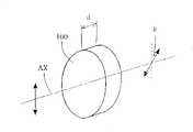
次之,圆锥柱状镜系统8,顺着光源侧,由对向光源侧为平面且对向罩幕侧为凹圆锥状的屈折面的第1棱镜部8a,与对向罩幕侧为平面且对向光源侧为凸圆锥状的屈折面的第2棱镜部8b所构成。第1棱镜部8a的凹圆锥状屈折面与第2棱镜部8b的凸圆锥状屈折面,是可接合而互补的形状。又,第1棱镜部8a与第2棱镜部8b的至少其一被构成可沿着光轴AX移动。第1棱镜部8a的凹圆锥状屈折面与第2棱镜部8b的凸圆锥状屈折面之间的间隔是可变的。Secondly, the conical
于此,对于第1棱镜部8a的凹圆锥状屈折面与第2棱镜部8b的凸圆锥状屈折面是相互接合的状态,圆锥柱状镜系统8做为平行平面板的机能,且不会影响到被形成的轮带状二次光源。然而,使第1棱镜部8a的凹圆锥状屈折面与第2棱镜部8b的凸圆锥状屈折面间离时,圆锥柱状镜系统8做为所谓光束扩展器的机能。因此,随着圆锥柱状镜系统8的间隔变化,变化向所定面7的入射光角度。Here, the concave conical inflection surface of the
图2,绘示相对轮带状二次光源,圆锥柱状镜系统的作用说明。参照图2,在设定圆锥柱状镜系统8的间隔为零且伸缩透镜9的焦点距离最小值的状态(以下称标准状态),被形成最小轮带状二次光源30a,利用使圆锥柱状镜系统8的间隔从零到所定值而扩大,其宽度(外径与内径的差的1/2:图中以箭号表示)不会变化,外径与内径一起扩大,而变化成轮带状二次光源30b。换言之,利用圆锥柱状镜系统8的作用,轮带状二次光源的宽度不会变化,其轮带比(内径/外径)与大小(外径)一起变化。Fig. 2 shows the description of the function of the conical cylindrical mirror system relative to the belt-shaped secondary light source. With reference to Fig. 2, be the state (hereinafter referred to as the standard state) of zero and the focal length minimum value of
图3绘示相对轮带状二次光源,伸缩透镜的作用说明。参照图3,在标准状态被形成的轮带状二次光源30a,利用伸缩透镜9的焦点距离从最小值到所定值扩大,其全体形状相似地扩大而变化成轮带状二次光源30c。换言之,利用伸缩透镜9的作用,轮带状二次光源的轮带比不会变化,其宽度与大小(外径)一起变化。FIG. 3 illustrates the function of the telescopic lens relative to the belt-shaped secondary light source. Referring to FIG. 3 , the belt-shaped secondary
图4绘示图1的偏光监视器的内部结构示意斜视图。参照图4,偏光监视器12包含:被配置于微复眼透镜11与集光系统13之间的光路的第1分光器12a。第1分光器12a例如是利用石英玻璃形成的没有涂布的平行面板(即是素玻璃)的型态,且其具有将与入射光的偏光状态相异的偏光状态的反射光从光路取出的机能。FIG. 4 is a schematic oblique view of the internal structure of the polarizing monitor shown in FIG. 1 . Referring to FIG. 4 , the polarization monitor 12 includes a
利用第1分光器12a而从光路被取出的光,入射于第2分光器12b。第2分光器12b与第1分光器12a相同,例如是利用石英玻璃形成的没有涂布的平行面板型态,且其具有使与入射光的偏光状态相异的偏光状态的反射光发生的机能。接着,进行设定使相对第1分光器12a的P偏光成为相对第2分光器12b的S偏光,且相对第1分光器12a的S偏光成为相对第2分光器12b的P偏光。The light extracted from the optical path by the
又,透过第2分光器12b的光是利用第1光度检测器12c而被检测,在第2分光器12b被反射的光是利用第2光度检测器12d而被检测。第1光度检测器12c与第2光度检测器12d的输出,分别被输给控制部(未示于图)。控制部依需要驱动构成偏光状态切换部4的1/4波长板4a、1/2波长板4b与消偏振镜4c。The light transmitted through the
如上述,关于第1分光器12a与第2分光器12b,对于P偏光的反射率与S偏光的反射率,实质上是不同。因此,对于偏光监视器12,从第1分光器12a的反射光,含有例如往第1分光器12a的入射光的约10%的S偏光成分(对第1分光器12a的S偏光成分是对第2分光器12b的P偏光成分),与例如往第1分光器12a的入射光的约1%的P偏光成分(对第1分光器12a的P偏光成分是对第2分光器12b的S偏光成分)。As described above, the
又,从第2分光器12b的反射光,含有例如往第1分光器12a的入射光的约10%×1%=0.1%的P偏光成分(对第1分光器12a的P偏光成分是对第2分光器12b的S偏光成分),与例如往第1分光器12a的入射光的约1%×10%=0.1%的的S偏光成分(对第1分光器12a的S偏光成分是对第2分光器12b的P偏光成分)。Also, the reflected light from the
如此,对于偏光监视器12,第1分光器12a回应其反射特性而具有将与入射光偏光状态相异的偏光状态的反射光从光路取出的机能。其结果,很少受到第2分光器12b造成的偏光变动的影响,根据第1光度检测器12c的输出(关于第2分光器12b的透过光强度资料,即是从第1分光器12a的反射光约相同偏光状态的光的强度资料),可以检知往第1分光器12a的入射光的偏光状态(偏光度),进而往罩幕M的照明光的偏光状态。In this way, with respect to the
又,对于偏光监视器12,被设定为相对第1分光器12a的P偏光为对第2分光器12b的S偏光,且对第1分光器12a的S偏光为对第2分光器12b的P偏光。其结果,根据第2光度检测器12d的输出(关于第1分光器12a与第2分光器12b被顺次反射光的强度资料),实质上不受往第1分光器12a的入射光的偏光状态的变化的影响,可以检知往第1分光器12a的入射光的光量(强度),进而往罩幕M的照明光的光量。Also, for the
接着,使用偏光监视器12,检知往第1分光器12a的入射光的偏光状态,进而可以判定是否往罩幕M的照明光是所要的非偏光状态、直线偏光状态、或圆偏光状态。控制部根据由偏光监视器12的检知结果,确认往罩幕M(进而晶圆W)的照明光是否为所要的非偏光状态、直线偏光状态、或圆偏光状态的情形,驱动调整构成偏光状态切换部4的1/4波长板4a、1/2波长板4b与消偏振镜4c,而可以调整往罩幕M的照明光的状态为所要的非偏光状态、直线偏光状态、或圆偏光状态。Next, the polarization monitor 12 is used to detect the polarization state of the incident light to the
再者,取代轮带照明用的绕射光学元件5的4极照明用的绕射光学元件(未示于图),藉由设定于照明光路中,可以进行4极照明。4极照明用的绕射光学元件,在入射有矩形状的断面的平行光束的情形,有在其远场形成4极状的光强度分布的机能。因此,穿过4极照明用的绕射光学元件的光束,在微复眼透镜11的入射面,形成例如以光轴AX做为中心的4个圆形状照射区域所组成的4极状照射区域。其结果,微复眼透镜11的后侧焦点面或其附近,与被形成于入射面的照射区域相同,被形成4极状的二次光源。Furthermore, quadrupole illumination can be performed by setting a quadrupole illumination diffractive optical element (not shown) in place of the rim illumination diffractive
又,取代轮带照明用的绕射光学元件5的圆形照明用的绕射光学元件(未示于图),藉由设定于照明光路中,可以进行一般的圆形照明。圆形照明用的绕射光学元件,在入射有矩形状的断面的平行光束的情形,有在其远场形成圆形状的光强度分布的机能。因此,穿过圆形照明用的绕射光学元件的光束,在微复眼透镜11的入射面,形成例如以光轴AX做为中心的圆形状照射区域所组成的4极状照射区域。其结果,微复眼透镜11的后侧焦点面或其附近,与被形成于入射面的照射区域相同,被形成圆形状的二次光源。In addition, a diffractive optical element (not shown) for circular illumination instead of the diffractive
再者,取代轮带照明用的绕射光学元件5的其他多极照明用的绕射光学元件(未示于图),藉由设定于照明光路中,可以进行各种多极照明(2极照明、8极照明等)。同样地,取代轮带照明用的绕射光学元件5的有适当特性的绕射光学元件,藉由设定于照明光路中,可以进行各种形态的变换照明。Furthermore, other diffractive optical elements (not shown) for multipole illumination instead of the diffractive
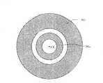
图5绘示图1的偏光变换元件的内部结构示意图。图6绘示水晶旋光性说明图。图7绘示利用偏光变换元件的作用,被设定成周方向偏光状态的轮带状二次光源示意图。根据本发明实施例的偏光变换元件10,被配置在微复眼透镜11的正前面,即是照明光学装置(1~PL)的瞳或其附近。因此,在轮带照明的情形,对偏光变换元件10入射有断面约轮带状且以光轴AX做为中心的光束。FIG. 5 is a schematic diagram of the internal structure of the polarization conversion element of FIG. 1 . Fig. 6 is an explanatory diagram of crystal optical activity. FIG. 7 is a schematic diagram of a ring-shaped secondary light source set in a peripheral polarization state by utilizing the function of a polarization conversion element. The
参照图5,偏光变换元件10,有全体光轴AX做为中心轮带状的有效区域,其轮带状的有效区域以光轴AX做为中心,利用在圆周方向等分成8个扇形形状的的基本元件被构成。在这些8个基本元件,夹着光轴AX相对的一对基本元件相互有相同特性。即是,8个基本元件,延着光穿过方向(Y方向)的厚度(光轴方向的长度)相互不同的4种基本元件10A~10D各含2个。Referring to Fig. 5, the
具体而言,设定成第1基本元件10A的厚度最大,第4基本元件10D的厚度最小,第2基本元件10B的厚度比第3基本元件10C的厚度大。其结果,偏光变换元件10的一方的面(例如入射面)为平面状,而另一面(例如出射面),利用各基本元件10A~10D的厚度不同,成为凹凸状。又,可以偏光变换元件10的双面(入射面与出射面)一起形成凹凸状。Specifically, the thickness of the first
又,本实施例,各基本元件10A~10D是利用有旋光性的光学材料亦即是做为结晶材料的水晶所构成,各基本元件10A~10D的结晶光学轴与光轴AX约一致,即是设定成与入射光的行进方向约一致。以下,参照图6,对于水晶的旋光性进行简单说明。参照图6,由厚度为d的水晶所构成的平行面板光学部材100,其结晶光学轴与光轴AX被配置成一致。如此情形,利用光学部材100的旋光性,入射的直线偏光的偏光方向对光轴AX仅旋转一角度θ的状态被射出。Also, in this embodiment, each of the
此时,光学部材100的旋光性造成偏光方向的旋转角(旋光角度)θ,利用光学部材100的厚度d与旋光能ρ,以下式(a)表示。At this time, the rotation angle (optical rotation angle) θ of the polarization direction due to the optical rotation of the
θ=d.ρ (a)θ=d.ρ (a)
一般,水晶的旋光能ρ,为波长依存性(依存使用光的波长其不同旋光能值:旋光分散),具体地,使用光的波长短,会有愈大的倾向。根据在《应用光学II》的第167页的记载,相对于具有250.3nm的波长的光,水晶的旋光能ρ为153.9度/mm。Generally, the optical rotation energy ρ of the crystal is wavelength-dependent (depending on the wavelength of the light used, the value of the optical rotation energy is different: optical rotation dispersion). Specifically, the shorter the wavelength of the used light, the greater the tendency. According to the description on page 167 of "Applied Optics II", the optical rotation energy ρ of crystal with respect to light having a wavelength of 250.3 nm is 153.9 degrees/mm.
在本实施例,第1基本元件10A,被设定成厚度dA,在Z方向偏光的直线偏光的光入射的情形,Z方向绕着Y轴使+180度旋转的方向,即是在Z方向有偏光方向的直线偏光的光使射出。因此,在此情形,如图7所示的轮带状二次光源31之中,受到一对第1基本元件10A的旋光作用的光束,通过形成的一对圆弧状区域31A的光束的偏光方向是在Z方向。In this embodiment, the first
第2基本元件10B,被设定成厚度dB,在Z方向偏光的直线偏光的光入射时,Z方向绕着Y轴使+135度旋转的方向,即是在Z方向绕着Y轴使-45度旋转的方向,有偏光方向的直线偏光的光射出。因此,在此情形,如图7所示的轮带状二次光源31之中,受到一对第2基本元件10B的旋光作用的光束,通过形成的一对圆弧状区域31B的光束的偏光方向,是Z方向绕着Y轴使旋转-45度的方向。The second
第3基本元件10C,被设定成厚度dC,在Z方向偏光的直线偏光的光入射时,Z方向绕着Y轴使+90度旋转的方向,即是有X方向偏光方向的直线偏光的光射出。因此,在此情形,如图7所示的轮带状二次光源31之中,受到一对第3基本元件10C的旋光作用的光束,通过形成的一对圆弧状区域31C的光束的偏光方向是在X方向。The third
第4基本元件10D,被设定成厚度dD,在Z方向偏光的直线偏光的光入射时,Z方向绕着Y轴使+45度旋转的方向有偏光方向的直线偏光的光射出。因此,在此情形,如图7所示的轮带状二次光源31之中,受到一对第4基本元件10D的旋光作用的光束,通过形成的一对圆弧状区域31D的光束的偏光方向,是Z方向绕着Y轴使旋转+45度的方向。The fourth
再者,对分别被形成的8个基本元件进行组合可以得到偏光变换元件10,也可以利用将平行平面板的水晶基板形成所要的凹凸形状(段差)而得到偏光变换元件10。又,不将偏光变换元件10从光路退开时,可以进行通常的圆形照明,且设定圆形状的中央光通过区域10E,其大小为偏光变换元件10的有效区域的径方向大小的大于等于3/10,较佳为大于等于1/3,且没有旋光性。于此,中央光通过区域10E,可以利用没有旋光性的光学材料例如石英而形成,也可以是简单的圆形状开口。但是,中央光通过区域10E不是偏光变换元件10的必要元件。再者,中央光通过区域10E的大小是由周方向偏光状态区域与非此区域的边界所决定。Furthermore, the
于本实施例,周方向偏光轮带照明时(通过轮带状的二次光源的光束被设定成周方向偏光状态的变形照明),有Z方向偏光的直线偏光的光被入射于偏光变换元件10。其结果,微复眼透镜11的后侧焦点面或其附近,如图7所示,轮带状的二次光源(轮带状的瞳分布)31被形成,通过此轮带状的二次光源31的光束被设定成周方向偏光状态。对于周方向偏光状态,分别通过构成轮带状的二次光源31的圆弧状区域31A~31D的光束,沿着各圆弧状区域31A~31D的圆周方向,而在中心位置的直线偏光状态的偏光方向是大约与以光轴AX做为中心的圆的切线方向一致。In this embodiment, when the peripheral polarized light beam is illuminated (deformed illumination in which the light beam passing through the secondary light source in the circular shape is set to the circumferentially polarized state), linearly polarized light with Z-direction polarization is incident on the polarization converter.
接着,于本实施例,与因光圈大而发生光量损失的传统技术不同,利用偏光变换元件10的旋光作用,不会有实质的光量损失发生,可以形成周方向偏光状态的轮带状的二次光源31。换言之,对于本实施例的照明光学装置,良好地抑制光量损失,可以形成周方向偏光状态的轮带状的照明分布。再者,对于本实施例,因为使用光学元件的偏光作用,偏光变换元件的制造容易,对于典型的各基本元件的厚度公差可以很缓设定,达到优良效果。Next, in the present embodiment, unlike the conventional technology in which light loss occurs due to a large aperture, the optical rotation effect of the
又,根据周方向偏光状态的轮带状照明瞳分布的周方向偏光轮带状照明,做为最终的被照明面的晶圆W被照射的光是以S偏光为主要成份的偏光状态。于此,S偏光,是有相对入射面垂直方向的偏光方向的直线偏光(垂直入射面的方向电性向量震动的偏光)。但是,入射面,定义为当光到达媒介质的界面(被照射面:晶圆W表面),包含在其点上的界面法线与入射光的面。In addition, according to the annular illumination pupil distribution of the circumferential polarization state, the light irradiated on the wafer W, which is the final illuminated surface, has a polarization state with S polarization as the main component. Here, the S-polarized light is linearly polarized light having a polarization direction perpendicular to the plane of incidence (polarized light whose electrical vector vibrates in a direction perpendicular to the plane of incidence). However, the incident surface is defined as the surface where the light reaches the interface of the medium (irradiated surface: surface of wafer W), including the interface normal at its point and the surface of the incident light.
其结果,对于周方向偏光轮带状照明,可以提升投影光学系统的光学性能(焦点深度等),可以得到在晶圆(感光性基板)上高对比的罩幕图案像。即是,对于本发明实施例,因为使用可以良好地抑制光量损失,且形成周方向偏光状态的轮带状照明瞳分布的照明光学装置,用适当的照明条件可以忠实且高产能地将微细图案转写。As a result, the optical performance (depth of focus, etc.) of the projection optical system can be improved for circumferential polarizer band illumination, and a high-contrast mask pattern image on the wafer (photosensitive substrate) can be obtained. That is, in the embodiment of the present invention, since the illumination optical device that can well suppress the loss of light quantity and form a ring-shaped illumination pupil distribution in the circumferential polarization state is used, it is possible to faithfully and high-yield the fine pattern under appropriate illumination conditions. transcribed.
接着,于本实施例,利用有X方向偏光方向的直线偏光的光使其入射偏光变换元件10,如图8所示通过轮带状二次光源32的光束设定为径方向偏光状态,且进行径方向偏光轮带照明(通过轮带状二次光源32的光束被设定成径方向偏光状态的变形照明)。于径方向偏光状态,分别通过构成轮带状二次光源32的圆弧状区域32A~32D的光束,沿着各圆弧状区域32A~32D的圆周方向,而在中心位置的直线偏光状态是大约与以光轴AX做为中心的圆的半径方式一致。Next, in this embodiment, the linearly polarized light with the X-direction polarization direction is used to make it incident on the
根据径方向偏光状态的轮带状照明瞳分布的径方向偏光轮带照明,被照射到做为最终的被照明面的晶圆W的光,是以P偏光为主要成份的偏光状态。于此,P偏光,是相对上述定义的入射面的平行方向的偏光方向的直线偏光(平行入射面方向电性向量震动的偏光)。其结果,径方向偏光轮带状照明,被涂布于晶圆上的光阻的光反射率减小,在晶圆(感光性基板)上,可以得到良好的罩幕图案像。Radial polarized zonal illumination based on radially polarized illumination pupil distribution in radial direction, the light irradiated to the wafer W as the final illuminated surface has a polarization state with P polarization as the main component. Here, P-polarized light is linearly polarized light (polarized light whose electrical vector vibrates in a direction parallel to the incident surface) with respect to the polarization direction parallel to the incident surface defined above. As a result, the light reflectance of the photoresist coated on the wafer is reduced by radial polarizer band illumination, and a good mask pattern image can be obtained on the wafer (photosensitive substrate).
又,于上述实施例,入射偏光变换元件10的光束,利用在Z方向有偏光方向的直线偏光状态与在X方向有偏光方向的直线偏光状态之间的切换,而实现周方向偏光轮带照明与径方向偏光轮带照明。但是,不限定于此,例如对于在Z方向或X方向有偏光方向的直线偏光状态的入射光束,利用偏光变换元件10在如图5所示的第1状态与绕着光轴AX使仅90度回转的第2状态之间切换,可以实现周方向偏光轮带照明与径方向偏光轮带照明。Moreover, in the above-mentioned embodiment, the light beam incident on the
又,于上述实施例,微复眼透镜11的正前方配置偏光变换元件10。但是,不限定于此,一般照明装置(1~PL)的瞳或其附近,例如投影光学系统PL的瞳或其附近,成像光学系统15的瞳或其附近,圆锥柱状镜系统8的正前方(无焦点透镜6的瞳或其附近)等可以配置偏光变换元件10。In addition, in the above-mentioned embodiment, the
因此,如果投影光学系统PL中与成像光学系统15中配置偏光变换元件10,因为偏光变换元件10所要的有效径容易大,考虑到有困难得到高品质的大水晶基板的现状而不佳。又,如果圆锥柱状镜系统8的正前方配置偏光变换元件10,可以使偏光变换元件10所要的有效径减小,但是到最终被照射面的晶圆W的距离长,防止透镜反射的涂布与镜子的反射膜等会改变偏光状态的因素容易介入在其光路中而不佳。即是,透镜的防止反射涂布与镜子的反射膜,容易由于偏光状态(P偏光与S偏光)与入射角的反射率而变差,进而容易变化偏光状态。Therefore, if the
又,于上述实施例,偏光变换元件10的至少其一面的(例如射出面)被形成凹凸状,进而偏光变换元件10在周方向有离散(不连续)变化厚度分布。但是,不限定于此,如偏光变换元件10在周方向具有约不连续变化的厚度分布,偏光变换元件10的至少其一面(例如射出面)可以形成曲面状。In addition, in the above-mentioned embodiment, at least one side of the polarization conversion element 10 (for example, the output surface) is formed in a concave-convex shape, and furthermore, the
又,于上述实施例,利用对应轮带状的有效区域的8分割的8个扇形状的基本元件,构成偏光变换元件10。但是,不限定于此,可以例如利用对应圆形状有效区域的8分割的8个扇形状的基本元件,或是利用对应圆形状或轮带状的有效区域的4个分割的4个扇形状的基本元件,或是利用对应圆形状或轮带状的有效区域的16个分割的16个扇形状的基本元件构成偏光变换元件10。即是,偏光变换元件10的有效区域形状,有效区域分割数(基本元件的数量)等,可以有多种不同的变形例。In addition, in the above-mentioned embodiment, the
又,于上述实施例,用水晶形成各种基本元件10A~10D(进而偏光变换元件10)。但是,不限定于此,使用有旋光性的其他适当光学材料可形成各基本元件。与此情形,也可以使用对应使用波长的光有100度/mm以上的旋光能的光学材料。即是,如果使用旋光能小的光学材料,要得到偏光方向所要的旋转角之所需的厚度会过厚,且由于光量损失的原因而不佳。Also, in the above-mentioned embodiment, the various
又,于上述实施例,偏光变换元件10对应照明光路固定设定,也可以使偏光变换元件10对应照明光路可以插脱设定。又,于上述实施例,虽然相对晶圆W的S偏光与轮带照明组合为例,也可以相对晶圆W的S偏光与2极或4极等的多极照明与圆形照明组合。又,于上述实施例,往罩幕M的照明条件与往晶圆W的成像条件(数值孔径与像差),例如罩幕M的图案的种类等因此可以自动设定。Moreover, in the above-mentioned embodiment, the
图9绘示多个偏光变换元件可以交换的变化示意图。又,图9的变形有例如图1所示的实施例类似的结构,其差异点在于其具有使多个偏光变换元件可以交换的转台10T(turret)。FIG. 9 is a schematic diagram showing a change in which a plurality of polarization conversion elements can be exchanged. Also, the modification of FIG. 9 has a structure similar to that of the embodiment shown in FIG. 1, but the difference lies in that it has a
图10绘示做为图9的交换机构的转台10T被载置多种偏光变换元件10a~10e示意图。如图9与图10所示,对于变形例,与光轴AX平行方向做为轴可以旋转的转台10T上,设置多种种类的偏光变换元件10a~10e,利用转台10T的旋转作用可以交换多种种类的偏光变换元件10a~10e。又,于图9,多种种类的偏光变换元件10a~10e之中,仅偏光变换元件10a,10b示于图。又,对于做为偏光变换元件的交换机构,不限定于转台10T,例如滑动件也可以。FIG. 10 is a schematic diagram of a
图11A~11E绘示多种偏光变换元件10a~10e分别的结构示意图。于图11A,第1偏光变换元件10a具有与图5所示的实施例的偏光变换元件10相同的结构。于图11B,第2偏光变换元件10b,虽然具有与图11A所示偏光变换元件10a类似的结构,但不同点是于中央光通过区域10E设置有偏光消解部材104c。此偏光消解部材104c,具有与图1所示的消偏振镜4c相同结构,且有将入射的直线偏光的光变换成非偏光状态的光的功能。11A-11E are schematic diagrams showing the structures of various
于图11C,第3偏光变换元件10c具有与图11A所示偏光变换元件10a类似结构,不同点在于中央光通过区域10E的大小较大(第1~第4基本元件10A~10D的宽度较窄)。又,于图11D,第4偏光变换元件10d具有与图11C所示偏光变换元件10c类似结构,差异点在于中央光通过区域10E设置偏光消解部材104c。In FIG. 11C, the third
于图11E,第5偏光变换元件10e,不是由8个基本元件所构成,而是由6个基本元件10C、10F、10G组合所构成。第5偏光变换元件10e,以做为全体的光轴AX做为中心有轮带状的有效区域,且此轮带状的有效区域以光轴AX做为中心,利用在圆周方向等分割成6个扇形状基本元件10C、10F、10G被构成。在这些6个扇形状基本元件10C、10F、10G,夹着光轴AX相对的一对基本元件相互有相同特性。即是,6个基本元件10C、10F、10G,沿着光的透过方向(Y方向)的厚度(光轴方向的长度)相互为异的3种类基本元件10C、10F、10G各含2个。In FIG. 11E, the fifth
接着,基本元件10C,与图7所示的第3基本元件10C有相同机能部材,而省略其机能说明。基本元件10F,被设定有厚度dF,在Z方向有偏光方向的直线偏光入射情形,Z方向绕着Y轴使旋转+150度的方向,即是Z方向绕着Y轴使旋转-30度的方向的偏光方向的直线偏光的光射出。基本元件10G,被设定有厚度dG,在Z方向有偏光方向的直线偏光入射情形,Z方向绕着Y轴使旋转+30度方向的偏光方向的直线偏光的光射出。又,取代中央光通过区域10E,也可以设置偏光消解部材104c。Next, the
又,回到图10,于转台10T上设置未载置偏光变换元件的开口部40,对于进行不是周方向偏光照明的偏光照明的情形,进行大的σ值(σ值=照明光学装置的罩幕侧数值孔径/投影光学系统的罩幕侧数值孔径)的非偏光照明的情形,此开口部40位于照明光路中。Also, referring back to FIG. 10 , an
又,如上述,被载置于转台10T的偏光变换元件10a~10e的中央部,虽然以由圆形状的开口或没有旋光性的材料构成中央光通过区域10E或是设置偏光消解部材104c为例示之,也可以配置没有设置中央光通过区域10E或偏光消解部材104c的偏光变换元件(由扇形状的基本元件所组成的偏光变换元件)。Also, as described above, the central part of the
图12A~12C绘示利用偏光变换元件的作用被设定成周方向偏光状态的二次光源的一例示意图。又,于图12A~12C,为容易理解的偏光变换元件,重绘于图示。12A to 12C are schematic diagrams showing an example of a secondary light source set to a circumferentially polarized state by utilizing the function of a polarization conversion element. In addition, in FIGS. 12A to 12C , the polarization conversion elements are redrawn for easy understanding.
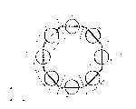
图12A,取代绕射光学元件5,在远场(或是Fraunhofer绕射区域)形成8极状的光强度分布的绕射光学元件(光束变换元件)被设置于光路中,且偏光变换元件10a或10b被设置于照明光路的情形,以8极状的二次光源33示之。因此,通过8极状的二次光源33的光束被设定成周方向偏光状态。对于周方向偏光状态,分别通过构成8极状的二次光源33的8个圆形区域33A~33D的光束,由8个圆形区域33A~33D结合成圆的圆周方向,即是与这些8个圆形区域33A~33D结合的圆的切线方向约一致的偏光方向的直线偏光状态。又,于图12A,虽然8极状的二次光源33以8个圆形区域33A~33D所构成为例示之,但不限定于有8个区域形状为圆形。12A, instead of the diffractive
图12B,取代绕射光学元件5,在远场(或是Fraunhofer绕射区域)形成4极状的光强度分布的绕射光学元件(光束变换元件)被设置于光路中,且偏光变换元件10c或10d被设置于照明光路的情形,以4极状的二次光源34示之。因此,通过4极状的二次光源34的光束被设定成周方向偏光状态。对于周方向偏光状态,分别通过构成4极状的二次光源34的4个区域34A、34C的光束,由4个区域34A、34C结合成圆的圆周方向,即是与这些4个区域34A、34C结合的圆的切线方向约一致的偏光方向的直线偏光状态。又,于图12B,虽然4极状的二次光源34以4个椭圆形区域34A、34C所构成为例示之,但不限定于4个区域形状为椭圆形。12B, instead of the diffractive
图12C,取代绕射光学元件5,在远场(或是Fraunhofer绕射区域)形成6极状的光强度分布的绕射光学元件(光束变换元件)被设置于光路中,且偏光变换元件10e被设置于照明光路的情形,以6极状的二次光源35示之。因此,通过6极状的二次光源35的光束被设定成周方向偏光状态。对于周方向偏光状态,分别通过构成6极状的二次光源35的6个区域35C、35F、35G的光束,由6个区域35C、35F、35G结合成圆的圆周方向,即是与这些6个区域35C、35F、35G结合的圆的切线方向约一致的偏光方向的直线偏光状态。又,于图12C,虽然6极状的二次光源35以6个约梯形状区域35C、35F、35G所构成为例示之,但不限定于6个区域形状为约梯形状。12C, instead of the diffractive
又,于上述实施例与变形例,虽然偏光变换元件绕着光轴被固定,偏光变换元件也可以绕着光轴使旋转。图13为设置成绕着光轴可以旋转的偏光变换元件10f的结构概略图。Also, in the above-mentioned embodiments and modifications, although the polarization conversion element is fixed around the optical axis, the polarization conversion element can also be rotated around the optical axis. Fig. 13 is a schematic diagram showing the structure of a
于图13,偏光变换元件10f,由4个基本元件10A、10C所组合构成。偏光变换元件10f有做为全体的光轴AX为中心的轮带状有效区域,且这轮带状有效区域以光轴AX为中心在圆周方向被等分割成4个扇形形状的基本元件10A、10C。在这4个基本元件10A、10C中,夹着光轴AX相对的一对基本元件相互有相同特性。即是,4个基本元件10A、10C,在沿着光穿过方向(Y方向)的厚度(光轴方向的长度)相互为异的2种基本元件10A、10C分别含2个。In FIG. 13, a
于此,因为基本元件10A是与图7所示的第1基本元件10A有相同机能的部材,基本元件10C是与图7所示的第3基本元件10C有相同机能的部材,而省略其机能说明。又,取代中央光通过区域10E的,也可以设置偏光消解部材104c。Here, since the
此偏光变换元件10f,以光轴AX做为中心设定成可以旋转,例如以光轴AX为中心使+45度或-45度可以旋转。图14A~14C绘示利用偏光变换元件10f的作用,被设定成周方向偏光状态的二次光源的一例示意图。又,于图14,为容易理解,偏光变换元件10f重复绘示。The
图14A,取代绕射光学元件5,在远场(或是Fraunhofer绕射区域)形成2极状的光强度分布的绕射光学元件(光束变换元件)被设置于光路中,且偏光变换元件10f在旋转角度为0度的状态(基准状态),在被设置于照明光路中的情形下以2极状的二次光源36(36A)示之。于此,通过二次光源36(36A)的光束被设定为纵方向偏光方向。In Fig. 14A, instead of the diffractive
图14B,取代绕射光学元件5,在远场(或是Fraunhofer绕射区域)形成4极状的光强度分布的绕射光学元件(光束变换元件)被设置于光路中,且偏光变换元件10f在旋转角度为0度的状态(基准状态),在被设置于照明光路中的情形下以4极状的二次光源37示之。于此,通过二次光源37的光束被设定为周方向偏光方向。又,于图14B,4极状的光强度分布局限在纸面内上下(Z方向)以及左右方向(X方向)。14B, instead of the diffractive
于周方向偏光状态,分别通过构成4极状的二次光源37的4个圆形区域37A、37C的光束,由这4个圆形区域37A、37C结合成的圆的圆周方向,即是有与这4个圆形区域37A、37C结合成的圆的切线方向约一致的偏光方向的直线偏光状态。又,于图14B,虽然是以4极状的二次光源37由4个圆形区域37A、37C所构成而示之,4个区域的形状不限定为圆形。In the circumferential polarization state, the light beams respectively passing through the four
图14C,取代图14B的绕射光学元件,在远场(或是Fraunhofer绕射区域)局限纸面内+45度(-135度)方向及纸面内-45度(+135度)方向,形成4极状的光强度分布的绕射光学元件(光束变换元件)被设置于光路中,且偏光变换元件10f在旋转角度为+45度的状态(相对基准状态,顺时钟旋转45度的状态)使旋转而设置于照明光路中的情形下,以4极状的二次光源38示之。Figure 14C replaces the diffractive optical element in Figure 14B, in the far field (or Fraunhofer diffraction area) to limit the direction of +45 degrees (-135 degrees) in the paper and the direction of -45 degrees (+135 degrees) in the paper, A diffractive optical element (beam conversion element) forming a quadrupole light intensity distribution is placed in the optical path, and the
于图14C,偏光状态切换部4中的1/2波长板4b绕着光轴使旋转,相对偏光变换元件10f,使有+45度(-135度方向)偏光方向的直线偏光入射。于此,因为基本元件10A有使入射的直线偏光的偏光方向仅旋转180度±n×180度(n为整数)的机能,且基本元件10C有使入射直线偏光的偏光方向仅旋转90度±n×180度(n为整数)的机能,通过4极状的二次光源38的光束被设定为周方向偏光状态。In FIG. 14C , the 1/2
于图14C所示的周方向偏光状态,分别通过构成4极状的二次光源38的4个圆形区域38B、38D的光束,由这4个圆形区域38B、38D结合成的圆的圆周方向,即是有与这4个圆形区域38B、38D结合成的圆的切线方向约一致的偏光方向的直线偏光状态。又,于图14C,虽然是以4极状的二次光源38由4个圆形区域38B、38D所构成的例子示之,4个区域的形状不限定为圆形。In the circumferential polarization state shown in FIG. 14C , light beams passing through the four
如此,利用偏光状态切换部4的偏光方向的变更动作,与偏光切换元件10f的旋转作用,虽然4极状二次光源局限在+45度(-135度)方向与-45度(+135度)方向,虽然4极状二次光源局限在0度(+180度)方向以及90度(270度)即是纵横方向,虽然2极状二次光源局限在0度(+180度)方向或90度(270度)即是纵横方向,也可以实现周方向偏光状态。In this way, using the changing action of the polarization direction of the polarization
又,以光轴AX做为中心在圆周方向被等分割而由8个扇形状的基本元件构成的偏光变换元件,也可以绕着光轴AX旋转。如图15A所示,例如由8分割的基本元件所构成的偏光变换元件(例如偏光变换元件10a),如果绕着光轴AX使仅旋转+45度,分别通过构成8极状二次光源39的8个圆形区域39A~39D的光束,具有相对此8个圆形区域39A~39D结合成的圆的圆周方向(8个圆形区域39A~39D结合成的圆的切线方向)使仅旋转-45度的偏光方向的直线偏光状态。Furthermore, the polarization conversion element, which is divided equally in the circumferential direction with the optical axis AX as the center and consists of eight fan-shaped basic elements, can also be rotated around the optical axis AX. As shown in FIG. 15A, for example, a polarization conversion element (for example,
又,如图15B所示,分别通过构成8极状二次光源的8个圆形区域的光束,在有相对此8个圆形区域结合成的圆的圆周方向(8个圆形区域结合成的圆的切线方向),长轴方向被仅旋转+45度的偏光方向的椭圆偏光的情形,如图15A所示的偏光变换元件(例如偏光变换元件10a),利用绕着光轴AX使仅旋转+45度,如图15C所示,可以得到约周方向偏光状态。Again, as shown in Figure 15B, the light beams passing through the 8 circular areas that constitute the 8-pole secondary light source respectively pass through the circumferential direction of the circle formed by the 8 circular areas (the 8 circular areas are combined into The tangential direction of the circle), the major axis direction is only rotated by +45 degrees in the case of elliptically polarized light in the polarization direction, the polarization conversion element (such as the
图16绘示偏光变换元件被配置在照明光学系统的瞳附近位置内、圆锥柱状镜系统8的正前面位置(入射侧附近位置)为例的示意图。于图16之例,利用伸缩透镜系统9的倍数变化作用,被投影到微复眼透镜11的入射面中央光通过区域10E的像的大小,与被投影到微复眼透镜11的入射面的各基本元件10A~10D的像的大小会被变更,藉由圆锥柱状镜系统8的动作,被投影到微复眼透镜11的入射面的各基本元件10A~10D的像,以光轴AX为中心的半径方向的幅度被变更。FIG. 16 shows a schematic diagram of an example where the polarization conversion element is disposed in the vicinity of the pupil of the illumination optical system, directly in front of the conical cylindrical mirror system 8 (near the incident side). In the example of FIG. 16 , the size of the image projected onto the central
因此,有如图16所示变形例的中央光通过区域10E(或是偏光消解部材104c)的偏光变换元件,比起有变换倍率作用的光学系统(伸缩透镜9)而设置在光源侧的情形,考虑中央光通过区域10E占据区域利用伸缩透镜9的变换倍率而被变更,也可以决定中央光通过区域10E的大小。Therefore, the polarization conversion element of the central
又,如图16所示的变形例,在有中央光通过区域10E(或是偏光消解部材104c)的偏光变换元件,比起有变更轮带比作用的光学系统(圆锥柱状镜系统8)而设置在光源侧的情形,如图17所示,较佳满足以下条件(1)与条件(2)的至少其一。In addition, in the modified example shown in FIG. 16, the polarization conversion element having the central
(1)(10in+ΔA)/10out<0.75(1)(10in+ΔA)/10out<0.75
(2)0.4<(10in+ΔA)/10out.(2)0.4<(10in+ΔA)/10out.
其中,in,
10in:偏光变换元件10的中央光通过区域10E的有效半径,10in: the effective radius of the central
10out:偏光变换元件10的外侧有效半径,10out: the outer effective radius of the
ΔA:通过有变更轮带比作用的光学系统的光束的内侧半径的增加部份。ΔA: The increase of the inner radius of the light beam passing through the optical system that changes the tire ratio.
于此,不满足条件(1)的情形,藉由偏光变换元件10使周方向偏光状态被变换的轮带状的区域狭窄,因为不能达成小轮带比的轮带状或多极状二次光源造成的周方向偏光照明而不好。又,不满足条件(2)的情形,可以通过偏光变换元件10的中央光通过区域的光束的直径明显变小,例如当该偏光变换元件10不会从照明光路外移,偏光状态不变,因为不能有小σ照明而不好。Here, if the condition (1) is not satisfied, the annulus-shaped region in which the polarization state in the circumferential direction is converted is narrowed by the
又,如图18所示,偏光变换元件被配置在照明光学系统的瞳附近位置中,比起微复眼透镜11是在罩幕侧的位置,具体地,也可以设置在将罩幕遮板14的像投影到罩幕上的成像光学系统15的瞳附近位置。在图16与图18所示的实施例,与图9到图11的实施例相同,也可以有多个能交换的偏光变换元件。Also, as shown in FIG. 18, the polarization conversion element is arranged in the vicinity of the pupil of the illumination optical system, which is closer to the mask side than the micro-fly-
又,在上述实施例,比起偏光变换元件10,晶圆W侧的光学系统(照明光学系统与投影光学系统)有偏光像差(延迟)的情形时,由于偏光像差,偏光方向会变化。于此情形,在考虑此光学系统的偏光像差的影响上,利用偏光变换元件10,较佳可以设定被旋转的偏光面的方向。又,利用偏光变换元件10,在晶圆W侧的光路中被配置反射部材的情形,被此反射部材反射在每个偏光方向产生相位差。此时,考虑由反射面的偏光特性引起的光束相位差,利用偏光变换元件10也可以设定被旋转的偏光面的方向。Also, in the above-mentioned embodiment, when the optical system (illumination optical system and projection optical system) on the wafer W side has polarization aberration (retardation) compared with the
接着,说明偏光状态的评量方法的实施例。于本实施例,保持做为感光性基板的晶圆W的晶圆平台(基板平台)的侧方,使用可以进出的晶圆面偏光监视器90,检测出到达做为感光性基板的晶圆W的光束的偏光状态。又,晶圆面偏光监视器90,也可以被设置在晶圆平台内,且也可以将该晶圆平台设置在别的计测平台上。Next, an embodiment of the evaluation method of the polarization state will be described. In this embodiment, the side of the wafer stage (substrate stage) holding the wafer W serving as the photosensitive substrate is used, and the polarized light monitor 90 that can enter and exit the wafer surface is used to detect the arrival of the wafer W serving as the photosensitive substrate. W is the polarization state of the beam. In addition, the wafer surface polarization monitor 90 may be installed in the wafer stage, and the wafer stage may be installed on another measurement stage.
图19绘示为了检出照明晶圆W的光的偏光状态以及光强度的晶圆面偏光监视器90的结构示意图。如图19所示,晶圆面偏光监视器90,包括可以定位于晶圆W的位置或其附近的针孔部材91。通过针孔部材91的针孔91a的光,穿过被配置在投影光学系统PL的像面位置或其附近,如前侧焦点位置的对准透镜92(collimated lens)而成为约平行的光束,并在被反射镜93反射后,入射于中继透镜系统94(relay lens)。穿过中继透镜系统94的约平行光束,穿过做为相位移动元件的1/4波长板95与做为偏光元件的偏光分光器96后,到达二维CCD 97(Charge Coupled Device,电荷耦合器件)的检测面97a。于此,二维CCD 97的检测面97a与投影光学系统PL的射出瞳大致光学共轭,进而与照明光学装置的照明瞳面大致光学共轭。FIG. 19 is a schematic structural diagram of a wafer surface polarization monitor 90 for detecting the polarization state and light intensity of the light illuminating the wafer W. Referring to FIG. As shown in FIG. 19 , the wafer surface polarization monitor 90 includes a
1/4波长板95,被构成能以光轴做为中心旋转,对于此1/4波长板95,被连接到为了被设定成以光轴做为中心旋转的设定部98。如此,对晶圆W的照明光的偏光度不是0的情形,藉由设定部98使1/4波长板95绕着光轴旋转,而变化在二维CCD 97的检测面97a光强度分布。因此,对于晶圆面偏光监视器90,一面使用设定部98而使1/4波长板95绕着光轴使旋转,而一面检测出在检测面97a光强度分布的变化,且从此检测结果到利用旋转相位移动元件的方法,可以测定照明光的偏光状态。The 1/4
又,旋转相位移动元件的方法,例如鹤田所描述的《光铅笔-给光技术者的应用光学》,如株式会社新技术通讯(communications)的详细记载。实际上,针孔部材91(进而针孔91a)沿着晶圆面使二维移动,在晶圆面的多个位置测定照明光的偏光状态。此时,对于晶圆面偏光监视器90,因为检测出在二维检测面97a的光强度分布的变化,根据此检测出的分布资料,在照明光的瞳内可以测定偏光状态的分布。Also, the method of rotating the phase shifting element, such as "Optical Pencil - Applied Optics for Optical Technologists" described by Tsuruta, is described in detail in Communications, Inc. Actually, the pinhole member 91 (and further, the pinhole 91 a ) is moved two-dimensionally along the wafer surface, and the polarization state of the illumination light is measured at a plurality of positions on the wafer surface. At this time, since the wafer surface polarization monitor 90 detects the change of the light intensity distribution on the two-
又,对于晶圆面偏光监视器90,做为相位移动元件的1/4波长板95可以取代使用1/2波长板。使用相位移动元件,偏光状态,即是用于测定4个Stokes参数,变化沿着相位移动元件与偏光元件(偏光分光器96)的光轴的相对角度,同时使相位移动元件或偏光元件从光路退开,依需要在至少4个相异状态检测出在检测面97a的光强度分布变化。又,于本实施例,虽然做为相位移动元件的1/4波长板95绕着光轴旋转,也可以使做为偏光元件的偏光分光器96绕着光轴旋转,也可以使相位移动元件与偏光元件二者绕着光轴旋转。又,取代这些操作或是增加这些操作的,也可以使做为相位移动元件的1/4波长板95与做为偏光元件的偏光分光器96的其一或二者从光路中插脱。Also, for the wafer surface polarization monitor 90, a 1/4
又,对于晶圆面偏光监视器90,利用反射镜93的偏光特性,是变化光的偏光状态。于此情形,因为预先知道的反射镜93的偏光特性,根据利用所需要的计算所得到对反射镜93的偏光特性的偏光状态的影响,补正晶圆面偏光监视器90的测定结果,可且正确地测定照明光的偏光状态。又,不限于反射镜,藉由变化由透镜等的其他光学部件引起偏光状态的情形以相同地补正测定结果,可以正确地测定照明光的偏光状态。In addition, the polarization monitor 90 on the wafer surface uses the polarization characteristics of the
以下,具体说明关于在照明光的瞳内的偏光状态分布的评量。首先,通过在瞳上的一点(或是微小区域),而到达像面上的一点(微小区域)的光线,一个一个算出对应的特定偏光度DSP。又,在以下说明,使用图1、图16、图18的XYZ座标系统。上述瞳上的一点(微小区域)对应二维CCD97的一画素,且像面上的一点(微小区域)对应针孔91a的XY座标系统。Hereinafter, the evaluation of the polarization state distribution in the pupil of the illumination light will be specifically described. First, the light rays that pass through a point (or tiny area) on the pupil and reach a point (tiny area) on the image plane calculate the corresponding specific degree of polarization DSP one by one. In addition, in the following description, the XYZ coordinate system of FIG. 1, FIG. 16, and FIG. 18 is used. A point (micro region) on the above-mentioned pupil corresponds to one pixel of the two-
此特定偏光度DSP,当在通过在瞳上的一点(或是微小区域),而到达像面上的一点(微小区域)的特定光线的X方向偏光成分(在瞳上X方向的振动方向的偏光)的强度为Ix,该特定光线的Y方向偏光成分(在瞳上Y方向的振动方向的偏光)的强度为Iy时,This specific degree of polarization DSP, when passing through a point (or a small area) on the pupil and reaching a point (a small area) on the image plane, the X-direction polarization component of the specific light (in the vibration direction of the X direction on the pupil) Polarized light) intensity is Ix, when the intensity of the Y-direction polarized light component of this particular light (on the polarized light of the vibration direction of Y-direction on the pupil) is Iy,
(3)DSP=(Ix-Iy)/(Ix+Iy)。(3) DSP=(Ix-Iy)/(Ix+Iy).
又,此特定偏光度DSP,对应全部强度S0的水平直线偏光强度减去垂直直线偏光强度S1,与(S1/S0)相同。Also, the specific degree of polarization DSP is equal to (S1 /S0 ), which is the horizontal linear polarization intensity corresponding to the overall intensity S0 minus the vertical linear polarization intensity S1 .
又,由通过在瞳上的一点(或是微小区域),而到达像面上的一点(微小区域)的特定光线的X方向偏光成分(在瞳上X方向的振动方向的偏光)的强度为Ix,以及该特定光线的Y方向偏光成分(在瞳上Y方向的振动方向的偏光)的强度为Iy,通过下式(4)、(5),可以定义于水平偏光(对应在图案面内水平方向延伸的罩幕图案的绕射光成为S偏光的偏光)的特定偏光率RSPh、与垂直偏光(对应在图案面内垂直方向延伸的罩幕图案的绕射光成为S偏光的偏光)的特定偏光率RSPv。Also, the intensity of the X-direction polarization component (polarized light in the X-direction vibration direction on the pupil) of a specific ray of light that passes through a point (or a small area) on the pupil and reaches a point (a small area) on the image plane is given by Ix, and the intensity of the Y-direction polarized light component (the polarized light of the Y-direction on the pupil) of this specific light is Iy, by the following formula (4), (5), can be defined in horizontally polarized light (corresponding to in the pattern plane The specific polarization ratio RSP h of the diffracted light of the mask pattern extending in the horizontal direction becomes S-polarized light), and the specific polarization ratio RSPh of vertically polarized light (the diffracted light corresponding to the mask pattern extending in the vertical direction in the pattern plane becomes S-polarized light) Polarization rate RSPv .
(4)RSPh=Ix/(Ix+Iy),(4) RSPh =Ix/(Ix+Iy),
(5)RSPv=Iy/(Ix+Iy),(5)RSPv =Iy/(Ix+Iy),
其中,当理想的非偏光照明时RSPh,RSPv二者为50%,当理想的水平偏光时RSPh为100%,当理想的垂直偏光时RSPv为100%。Wherein, RSPh and RSPv are both 50% under ideal non-polarized lighting, RSPh is 100% under ideal horizontally polarized light, and RSPv is 100% under ideal vertically polarized light.
又,对应通过在瞳上的一点(或是微小区域)而到达像面上的一点(微小区域)的光线的一个一个,当用以下式(6)~(9)定义偏光度V时,对应通过所要的有效光源区域而到达像面上的一点(微小区域)的光束,可以用下式(10)定义平均偏光度V(Ave)。Also, corresponding to each of the light rays that pass through a point (or a small area) on the pupil and arrive at a point (a small area) on the image plane, when the degree of polarization V is defined by the following formulas (6) to (9), the corresponding The average degree of polarization V(Ave) of the light beam passing through the desired effective light source area and reaching one point (micro area) on the image plane can be defined by the following equation (10).
(6)V=(S12+S22+S32)1/2/S0(6) V=(S12 +S22 +S32 )1/2 /S0
=(S1’2+S 2’2+S3’2)1/2=(S1 '2 +S2 '2 +S3 '2 )1/2
(7)S1’=S1/S0(7) S1 '=S1 /S0
(8)S2’=S2/S0(8) S2 '=S2 /S0
(9)S3’=S3/S0(9) S3 '=S3 /S0
其中S0为全部强度,S1为水平直线偏光强度减去垂直直线偏光强度,S2为45度直线偏光强度减去135度直线偏光强度,S3为右旋圆偏光强度减去左旋圆偏光强度。Where S0 is the full intensity, S1 is the horizontal linear polarization intensity minus the vertical linear polarization intensity, S2 is the 45-degree linear polarization intensity minus 135-degree linear polarization intensity, and S3 is the right-handed circular polarization intensity minus the left-handed circular polarization intensity strength.
(10)V(Ave)=∑[S0(xi,yi).V(xi,yi)]/∑S0(xi,yi)。(10) V(Ave)=∑[S0 (xi, yi ).V(xi, yi )]/∑S0 (xi , yi ).
又,于式(10),S0(xi,yi)是对应通过所要的有效光源区域(xi,yi)上的一点(或是微小区域)而到达像面上的一点(微小区域)的光线的全部强度S0,V(xi,yi)是对应通过所要的有效光源区域(xi,yi)上的一点(或是微小区域)而到达像面上的一点(微小区域)的光线的偏光度。Also, in formula (10), S0 (xi, yi ) corresponds to a point (or tiny area) on the desired effective light source area (xi , yi ) and reaches a point on the image plane (tiny area) of the total intensity S0 of the light, V(xi, yi ) corresponds to a point (or a small area) on the desired effective light source area (xi , yi ) and reaches a point on the image plane ( The degree of polarization of light in a tiny region).
又,对应通过所要的有效光源区域而到达像面上的一点(微小区域)的光线,用下式(11)可以定义关于水平偏光的平均特定偏光率RSPh(Ave),用下式(12)可以定义关于垂直偏光的平均特定偏光率RSPv(Ave)。Also, corresponding to the light rays that pass through the desired effective light source area and arrive at a point (tiny area) on the image plane, the average specific polarization rate RSPh (Ave) for horizontally polarized light can be defined by the following formula (11), and the following formula (12 ) can define the average specific polarization ratio RSPv (Ave) with respect to vertically polarized light.
(11)RSPh(Ave)=Ix(Ave)/(Ix+Iy)Ave(11) RSPh (Ave) = Ix(Ave)/(Ix+Iy)Ave
=∑[S0(xi,yi).RSPh(xi,yi)]/∑S0(xi,yi),=∑[S0 (xi, yi ).RSPh (xi, yi )]/∑S0 (xi ,yi ),
(12)RSPv(Ave)=Iy(Ave)/(Ix+Iy)Ave(12) RSPv (Ave) = Iy(Ave)/(Ix+Iy)Ave
=∑[S0(xi,yi).RSPv(xi,yi)]/∑S0(xi,yi),=∑[S0 (xi, yi ).RSPv (xi, yi )]/∑S0 (xi, yi ),
其中1x(Ave)是通过所定的有效光源区域(xi,yi)而到达像面上的一点(微小区域)的光线在X方向偏光成分(在瞳上X方向的振动方向的偏光)的强度平均,Iy(Ave)是通过所定的有效光源区域(xi,yi)而到达像面上的一点(微小区域)的光线在Y方向偏光成分(在瞳上Y方向的振动方向的偏光)的强度平均,RSPh(xi,yi)是通过所定的有效光源区域(xi,yi)而到达像面上的一点(微小区域)的光线的在水平偏光的特定偏光率,RSPv(xi,yi)是通过所定的有效光源区域(xi,yi)而到达像面上的一点(微小区域)的光线的在垂直偏光的特定偏光率。又,(Ix+Iy)Ave是通过所定的有效光源区域的全部光束的强度平均。Among them, 1x(Ave) is the polarized component of the light in the X direction (the polarization of the vibration direction in the X direction on the pupil) of the light that passes through the effective light source area (xi , yi ) and reaches a point (small area) on the image plane. Intensity average, Iy(Ave) is the polarization component of the light in the Y direction of the light that passes through the effective light source area (xi , yi ) and reaches a point (small area) on the image plane (the polarization of the vibration direction in the Y direction on the pupil ), RSPh (xi, yi ) is the specific polarization rate of the light in the horizontal polarization of the light that passes through the effective light source area (xi, yi ) and reaches a point (tiny area) on the image plane, RSPv (xi, yi ) is the specific polarization rate of the light in the vertical polarization of the light that passes through the specified effective light source area (xi , yi ) and reaches a point (small area) on the image plane. Also, (Ix+Iy)Ave is the average intensity of all light beams passing through the predetermined effective light source area.
于此,当理想的非偏光照明时RSPh(xi,yi),RSPv(xi,yi)二者为50%,当理想的水平偏光时RSPh(xi,yi)为100%,当理想的垂直偏光时RSPv(xi,yi)为100%。Here, RSPh (xi , yi ) and RSPv (xi, yi ) are both 50% under ideal non-polarized lighting, and RSPh (xi , yi ) under ideal horizontally polarized light is 100%, and RSPv (xi , yi ) is 100% when the ideal vertically polarized light is applied.
接着,对应通过所定的有效光源区域(xi,yi)而到达像面上的一点(微小区域)的光束,可以用下式(13)定义平均特定偏光度DSP(Ave)。Next, the average specific degree of polarization DSP(Ave) can be defined by the following equation (13) corresponding to the light beam passing through the predetermined effective light source area (xi, yi ) and reaching a point (small area) on the image plane.
(13)DSP(Ave)=(Ix-Iy)Ave/(Ix+Iy)Ave(13) DSP(Ave)=(Ix-Iy)Ave/(Ix+Iy)Ave
={∑[Ix(xi,yi)-Iy(xi,yi)]/∑[Ix(xi,yi)+Iy(xi,yi)]}={∑[Ix(xi , yi )-Iy(xi , yi )]/∑[Ix(xi , yi )+Iy(xi , yi )]}
=S1’(Ave)=S1 '(Ave)
={∑S1/∑S0}={∑S1 /∑S0 }
于此,(Ix-Iy)Ave是通过所定的有效光源区域(xi,yi)而到达像面上的一点(微小区域)的光束在X方向偏光成分的强度与平均通过所定的有效光源区域(xi,yi)而到达像面上的一点(微小区域)的光束在Y方向偏光成分的强度的相差的平均,Ix(xi,yi)是通过所定的有效光源区域(xi,yi)而到达像面上的一点(微小区域)的光束在X方向偏光成分的强度,Iy(xi,yi)是通过所定的有效光源区域(xi,yi)而到达像面上的一点(微小区域)的光束在Y方向偏光成分的强度,S1’(Ave)是在所定的有效光源区域(xi,yi)的S1’成分的平均。Here, (Ix-Iy)Ave is the difference between the intensity of the polarized component of the light beam passing through the specified effective light source area (xi , yi ) and reaching a point (small area) on the image plane in the X direction and the average value of the light beam passing through the specified effective light source area. area (xi , yi ) and reach a point (tiny area) on the image plane, the average of the intensity difference of the polarized component of the light beam in the Y direction, Ix (xi , yi ) is the effective light source area (xi , yi ) and reach a point (small area) on the image plane, the intensity of the polarized light component of the beam in the X direction, Iy (xi , yi ) is reached through the specified effective light source area (xi , yi ) The intensity of the polarized component of the light beam at a point (tiny area) on the image plane in the Y direction, S1 '(Ave) is the average of the S1 ' component in the specified effective light source area (xi , yi ).
于式(13),当理想的非偏光照明时DSP(Ave)为0,当理想的水平偏光时DSP(Ave)为1,当理想的垂直偏光时DSP(Ave)为-1。In formula (13), DSP(Ave) is 0 under ideal non-polarized light, DSP(Ave) is 1 under ideal horizontally polarized light, and DSP(Ave) is -1 under ideal vertically polarized light.
现在,本实施例的照明光学装置,进而曝光装置,在所定的有效光源区域(xi,yi)的平均特定偏光率RSPh(Ave),RSPv(Ave)满足Now, the illumination optical device of this embodiment, and thus the exposure device, the average specific polarization ratio RSPh (Ave) and RSPv (Ave) in the predetermined effective light source area (xi , yi ) satisfy
RSPh(Ave)>70%,RSPv(Ave)>70%,RSPh (Ave) > 70%, RSPv (Ave) > 70%,
可看到在所定的有效光源区域内是直线偏光。于此,当平均特定偏光率RSPh(Ave),RSPv(Ave)不满足上式条件的情形,在周方向偏光轮带照明,或是周方向偏光四极照明、周方向偏光二极照明等,在所定方向有偏光面因为不是所希望的直线偏光状态,对于有特定指向(pitch)方向的线宽度的细图案不能向上提升成像能力。It can be seen that linearly polarized light is within the specified effective light source area. Here, when the average specific polarizing ratio RSPh (Ave) and RSPv (Ave) do not meet the conditions of the above formula, in the circumferential direction polarized wheel belt illumination, or the circumferential direction polarized quadrupole illumination, the circumferential direction polarized diode illumination etc. Since there is a polarizing surface in a given direction because it is not the desired linear polarization state, the imaging capability cannot be improved upward for a fine pattern with a line width in a specific pitch direction.
又,如图13所示,使用4分割偏光变换元件10进行4分割周方向偏光轮带照明的情形,如图20所示,轮带形状的二次光源31为4分割,也可以对每一个分割区域31A1、31A2、31C1、31C2的平均特定偏光率RSPh(Ave),RSPv(Ave)进行评量。Also, as shown in FIG. 13, in the case of using the 4-divided
对于上述实施例的曝光装置,藉由照明光学装置以照明罩幕(十字标记)(照明步骤),藉由使用投影光学系统将被形成于罩幕转印用的图案在感光性基板曝光(曝光步骤),可以制造微元件(半导体元件、拍摄元件、液晶显示元件、薄膜电磁头等)。以下,使用上述实施例的曝光装置,以在做为感光性基板的晶圆等形成电路图案,而得到做为微元件的半导体元件的实际方法为例,参照图21的流程图做说明。In the exposure apparatus of the above-mentioned embodiment, the mask (cross mark) is illuminated by the illumination optical device (illumination step), and the pattern formed on the mask transfer is exposed on the photosensitive substrate by using the projection optical system (exposure). step), micro components (semiconductor components, camera components, liquid crystal display components, thin film electromagnetic heads, etc.) can be manufactured. Hereinafter, using the exposure apparatus of the above-mentioned embodiment, an actual method of forming a circuit pattern on a wafer as a photosensitive substrate to obtain a semiconductor element as a micro element will be described with reference to the flow chart of FIG. 21 .
首先,于图21的步骤301,在一批次的晶圆上蒸镀金属膜。于下一步骤302,在这些一批次的晶圆上的金属膜上涂布光刻胶。之后,于步骤303,使用上述实施例的曝光装置,使罩幕上的图案的像通过投影光学系统,在这一批次的晶圆上的每个拍摄区域,顺次被曝光转印。之后,于步骤304,进行这一批次的晶圆上的光刻胶显影后,于步骤305,藉由在这一批次的晶圆上的光刻胶图案做为罩幕而进行蚀刻,因此,对应罩幕上图案的电路图案,被形成于每个晶圆的每个拍摄区域。之后,藉由进行更上层的电路图案的形成等,使半导体元件等的元件被制造。根据上述半导体元件等的制造方法,有极微细电路图案的半导体元件可以有良好的产能。First, in step 301 of FIG. 21 , a metal film is evaporated on a batch of wafers. In the next step 302, a photoresist is coated on the metal film on the batches of wafers. Afterwards, in step 303 , using the exposure device of the above-mentioned embodiment, the image of the pattern on the mask passes through the projection optical system, and each shot area on the wafer of this batch is sequentially exposed and transferred. Afterwards, in step 304, after developing the photoresist on this batch of wafers, in step 305, etching is performed by using the photoresist pattern on this batch of wafers as a mask, Therefore, a circuit pattern corresponding to the pattern on the mask is formed in each shot area of each wafer. Thereafter, elements such as semiconductor elements are manufactured by performing formation of upper layer circuit patterns and the like. According to the above method of manufacturing a semiconductor element and the like, a semiconductor element having an extremely fine circuit pattern can be produced with good yield.
又,对于上述实施例的曝光装置,利用在平板(玻璃基板)上,形成所定的图案(电路图案、电极图案等),可以得到做为微元件的液晶显示元件。以下,参照图22的流程图做为一例说明。在图22,于图案形成步骤401,使用上述实施例的曝光装置,在感光性基板(被涂布有光刻胶的玻璃基板等)转印曝光罩幕的图案,所谓的微影制程被进行。利用此微影制程步骤,在感光性基板上,含有多个电极等所定的图案被形成。之后,被曝光的基板,利用经过显影步骤,蚀刻步骤,移除光刻胶步骤等的各步骤,基板上所定的图案被形成,接着进行彩色滤光器(color filter)形成步骤402。Also, with the exposure apparatus of the above-mentioned embodiments, a liquid crystal display element as a micro element can be obtained by forming a predetermined pattern (circuit pattern, electrode pattern, etc.) on a flat plate (glass substrate). Hereinafter, an example will be described with reference to the flowchart of FIG. 22 . In FIG. 22, in the pattern forming step 401, using the exposure apparatus of the above-mentioned embodiment, the pattern of the exposure mask is transferred on the photosensitive substrate (glass substrate coated with photoresist, etc.), and the so-called photolithography process is performed. . Using this lithography process step, a predetermined pattern including a plurality of electrodes is formed on the photosensitive substrate. Afterwards, the exposed substrate is subjected to various steps such as developing, etching, and photoresist removal to form a predetermined pattern on the substrate, followed by a color filter forming step 402 .
对于彩色滤光器形成步骤402,对应红、绿、蓝3个点为一组,被形成矩阵状的多条配列,或是红、绿、蓝的3条的滤光器为一组配列成多个水平扫描线方向,而形成彩色滤光器。接着,在彩色滤光器形成步骤402之后,单元组合步骤403被进行。于单元组合步骤403,组装有由图案形成步骤401所得到的所定图案的基板,以及使用由彩色滤光器形成步骤402得到的彩色滤光器等,而得到液晶面板(液晶单元)。For the color filter forming step 402, three dots corresponding to red, green, and blue are formed as a group, and a plurality of arrays are formed in a matrix, or three optical filters of red, green, and blue are arranged as a group. A plurality of horizontal scanning line directions form a color filter. Next, after the color filter forming step 402, a cell combining step 403 is performed. In the cell assembly step 403 , a liquid crystal panel (liquid crystal cell) is obtained by assembling the substrate having the predetermined pattern obtained in the pattern forming step 401 and using the color filter obtained in the color filter forming step 402 .
单元组合步骤403,例如,在由图案形成步骤401所得到的所定图案的基板,以及使用由彩色滤光器形成步骤402所得到的彩色滤光器之间注入液晶,而制造液晶面板(液晶单元)。之后,于模块的组合步骤404,进行被组合的液晶面板(液晶单元)的显示动作的电路,背光模块等的各部件安装,使完成做为液晶显示元件。根据上述液晶显示元件的制造方法,可以得到有极微细电路图案的液晶显示件,并使其有良好产能。In the cell combining step 403, for example, liquid crystal is injected between the substrate of the predetermined pattern obtained in the pattern forming step 401 and the color filter obtained in the color filter forming step 402 to manufacture a liquid crystal panel (liquid crystal cell ). Afterwards, in the
又,对于上述实施例,做为曝光的光,虽然使用KrF准分子激光光(波长248nm)或是ArF准分子激光光(波长193nm),但不限定于此,其他适合的光源,例如供给波长157nm的激光光的F2激光光源等,也可以适用本发明。再者,对于上述实施例,包括照明光学装置的曝光装置为例做说明,但是为了照明罩幕或晶圆以外的被照射面的一般照明光学装置,可知地,也可以使用本发明。Also, for the above-mentioned embodiment, although KrF excimer laser light (wavelength 248nm) or ArF excimer laser light (wavelength 193nm) is used as the light for exposure, it is not limited thereto, and other suitable light sources, such as supply wavelength The present invention can also be applied to an F2 laser light source of 157 nm laser light or the like. Furthermore, in the above-mentioned embodiments, an exposure apparatus including an illumination optical device is described as an example, but it is understood that the present invention can also be applied to a general illumination optical apparatus for illuminating surfaces to be irradiated other than a mask or a wafer.
又,于上述实施例,投影光学系统与感光性基板之间的光路中,也可以使用填满有折射率大于等于1.1的媒介物(典型的液体)的方法,即所谓的液浸法。于此情形,做为投影光学系统与感光性基板之间的光路中填满液体的方法,可以采用已在国际公开号WO99/49504中被揭示的局部填满液体,特开平6-124873也揭示保持曝光对象的基板的平台在液槽中使移动的方法,日本专利特开平10-303114也揭示在平台上形成所定深度的液槽,且在其中保持基板等的方法。Furthermore, in the above embodiments, the optical path between the projection optical system and the photosensitive substrate may also be filled with a medium (typically liquid) with a refractive index greater than or equal to 1.1, that is, the so-called liquid immersion method. In this case, as a method of filling the liquid in the optical path between the projection optical system and the photosensitive substrate, partial filling of the liquid disclosed in International Publication No. WO99/49504, also disclosed in Japanese Unexamined Patent Publication Hei 6-124873 As a method of moving a stage holding a substrate to be exposed in a liquid tank, Japanese Patent Laid-Open No. 10-303114 also discloses a method of forming a liquid tank of a predetermined depth on the stage and holding a substrate therein.
又,做为液体,较佳使用可以对曝光的光有穿透性且高折射率,而相对投影光学系统与基板表面被涂布的光阻是安定的液体,例如以KrF准分子激光光或是ArF准分子激光光做为曝光的光的情形,做为液体的可以使用纯水、去离子水。又,使用做为曝光的光的F2激光的情形,作为液体的有可以使用可以透过F2激光光,例如氟素系油或氟化聚醚(PFPE)等的氟素系液体。Also, as the liquid, it is preferable to use a liquid that can penetrate the exposed light and has a high refractive index, and is stable relative to the projection optical system and the photoresist coated on the surface of the substrate, such as KrF excimer laser light or In the case of ArF excimer laser light as the exposure light, pure water or deionized water can be used as the liquid. Also, when usingF2 laser light as the exposure light, a fluorine-based liquid such as fluorine-based oil or fluorinated polyether (PFPE) that transmitsF2 laser light can be used as the liquid.
Claims (33)
Translated fromChineseApplications Claiming Priority (3)
| Application Number | Priority Date | Filing Date | Title |
|---|---|---|---|
| JP030555/2004 | 2004-02-06 | ||
| JP2004030555 | 2004-02-06 | ||
| JP358218/2004 | 2004-12-10 |
Related Child Applications (6)
| Application Number | Title | Priority Date | Filing Date |
|---|---|---|---|
| CN2007101109497ADivisionCN101078812B (en) | 2004-02-06 | 2005-01-14 | Polarizing transforming element, optical lighting device, exposure device and exposure method |
| CN200710110950.XADivisionCN101078813B (en) | 2004-02-06 | 2005-01-14 | Polarizing transforming element, optical lighting device, exposure device and exposure method |
| CN2008101266596ADivisionCN101320136B (en) | 2004-02-06 | 2005-01-14 | Polarization conversion element, lighting optical device, exposure system, and exposure method |
| CN2007101109482ADivisionCN101078811B (en) | 2004-02-06 | 2005-01-14 | Polarizing transforming element, optical lighting device, exposure device and exposure method |
| CN2007101109514ADivisionCN101078814B (en) | 2004-02-06 | 2005-01-14 | Polarizing transforming element, optical lighting device, exposure device and exposure method |
| CN2007101109529ADivisionCN101078888B (en) | 2004-02-06 | 2005-01-14 | Polarizing transforming element, optical lighting device, exposure device and exposure method |
Publications (2)
| Publication Number | Publication Date |
|---|---|
| CN1914525A CN1914525A (en) | 2007-02-14 |
| CN100409045Ctrue CN100409045C (en) | 2008-08-06 |
Family
ID=37722625
Family Applications (7)
| Application Number | Title | Priority Date | Filing Date |
|---|---|---|---|
| CN2007101109482AExpired - Fee RelatedCN101078811B (en) | 2004-02-06 | 2005-01-14 | Polarizing transforming element, optical lighting device, exposure device and exposure method |
| CN2008101266596AExpired - Fee RelatedCN101320136B (en) | 2004-02-06 | 2005-01-14 | Polarization conversion element, lighting optical device, exposure system, and exposure method |
| CN2007101109529AExpired - Fee RelatedCN101078888B (en) | 2004-02-06 | 2005-01-14 | Polarizing transforming element, optical lighting device, exposure device and exposure method |
| CNB2005800031865AExpired - LifetimeCN100409045C (en) | 2004-02-06 | 2005-01-14 | Polarization conversion element, optical illumination device, exposure device, and exposure method |
| CN2007101109497AExpired - Fee RelatedCN101078812B (en) | 2004-02-06 | 2005-01-14 | Polarizing transforming element, optical lighting device, exposure device and exposure method |
| CN200710110950.XAExpired - Fee RelatedCN101078813B (en) | 2004-02-06 | 2005-01-14 | Polarizing transforming element, optical lighting device, exposure device and exposure method |
| CN2007101109514AExpired - Fee RelatedCN101078814B (en) | 2004-02-06 | 2005-01-14 | Polarizing transforming element, optical lighting device, exposure device and exposure method |
Family Applications Before (3)
| Application Number | Title | Priority Date | Filing Date |
|---|---|---|---|
| CN2007101109482AExpired - Fee RelatedCN101078811B (en) | 2004-02-06 | 2005-01-14 | Polarizing transforming element, optical lighting device, exposure device and exposure method |
| CN2008101266596AExpired - Fee RelatedCN101320136B (en) | 2004-02-06 | 2005-01-14 | Polarization conversion element, lighting optical device, exposure system, and exposure method |
| CN2007101109529AExpired - Fee RelatedCN101078888B (en) | 2004-02-06 | 2005-01-14 | Polarizing transforming element, optical lighting device, exposure device and exposure method |
Family Applications After (3)
| Application Number | Title | Priority Date | Filing Date |
|---|---|---|---|
| CN2007101109497AExpired - Fee RelatedCN101078812B (en) | 2004-02-06 | 2005-01-14 | Polarizing transforming element, optical lighting device, exposure device and exposure method |
| CN200710110950.XAExpired - Fee RelatedCN101078813B (en) | 2004-02-06 | 2005-01-14 | Polarizing transforming element, optical lighting device, exposure device and exposure method |
| CN2007101109514AExpired - Fee RelatedCN101078814B (en) | 2004-02-06 | 2005-01-14 | Polarizing transforming element, optical lighting device, exposure device and exposure method |
Country Status (1)
| Country | Link |
|---|---|
| CN (7) | CN101078811B (en) |
Cited By (1)
| Publication number | Priority date | Publication date | Assignee | Title |
|---|---|---|---|---|
| CN103135363A (en)* | 2013-01-30 | 2013-06-05 | 中国科学院上海光学精密机械研究所 | Device for producing projection photo-etching illumination mode |
Families Citing this family (6)
| Publication number | Priority date | Publication date | Assignee | Title |
|---|---|---|---|---|
| KR101884486B1 (en)* | 2010-09-28 | 2018-08-01 | 칼 짜이스 에스엠티 게엠베하 | Optical system of a microlithographic projection exposure apparatus and method of reducing image placement errors |
| KR102170875B1 (en)* | 2011-10-24 | 2020-10-28 | 가부시키가이샤 니콘 | Illumination optical assembly, exposure apparatus, and device manufacturing method |
| CN104220931B (en)* | 2012-03-29 | 2016-10-12 | 卡尔蔡司Smt有限责任公司 | Apparatus and method for compensating channel defects of a microlithography projection exposure system |
| JP5897989B2 (en)* | 2012-05-28 | 2016-04-06 | 富士フイルム株式会社 | System for selectively irradiating specific circularly polarized light onto an object |
| CN102830499B (en)* | 2012-09-05 | 2015-01-21 | 山东大学 | Vector light field converter and polarized light converting method |
| CN104777545B (en)* | 2015-05-05 | 2018-05-01 | 武汉大学 | Silicon nano brick array polarization beam splitter |
Citations (9)
| Publication number | Priority date | Publication date | Assignee | Title |
|---|---|---|---|---|
| JPH0653120A (en)* | 1992-07-27 | 1994-02-25 | Nikon Corp | Lighting optics |
| JPH06188169A (en)* | 1992-08-24 | 1994-07-08 | Canon Inc | Imaging method, exposure apparatus using the method, and device manufacturing method using the method |
| JPH09184918A (en)* | 1995-09-23 | 1997-07-15 | Carl Zeiss:Fa | Radiation polarizing optical structure and microlithography projection exposure device provided with the same |
| JPH10104427A (en)* | 1996-10-03 | 1998-04-24 | Sankyo Seiki Mfg Co Ltd | Wavelength plate, and optical pickup unit equipped with the same |
| US5867315A (en)* | 1995-07-31 | 1999-02-02 | Pioneer Electronic Corporation | Crystal optic lens and an optical system for an optical pickup device |
| JP2002075816A (en)* | 2000-08-24 | 2002-03-15 | Asahi Optical Co Ltd | Beam train detection method and detection phase filter |
| JP2003035822A (en)* | 2001-05-22 | 2003-02-07 | Carl Zeiss Semiconductor Manufacturing Technologies Ag | Polariscope and microlithography projection system provided with the same |
| JP2003059821A (en)* | 2001-05-15 | 2003-02-28 | Carl Zeiss Semiconductor Manufacturing Technologies Ag | Optical imaging system having polarizer and quartz plate used therefor |
| JP2003297727A (en)* | 2002-04-03 | 2003-10-17 | Nikon Corp | Illumination optical device, exposure apparatus and exposure method |
Family Cites Families (1)
| Publication number | Priority date | Publication date | Assignee | Title |
|---|---|---|---|---|
| DE19807120A1 (en)* | 1998-02-20 | 1999-08-26 | Zeiss Carl Fa | Optical system with polarization compensator |
- 2005
- 2005-01-14CNCN2007101109482Apatent/CN101078811B/ennot_activeExpired - Fee Related
- 2005-01-14CNCN2008101266596Apatent/CN101320136B/ennot_activeExpired - Fee Related
- 2005-01-14CNCN2007101109529Apatent/CN101078888B/ennot_activeExpired - Fee Related
- 2005-01-14CNCNB2005800031865Apatent/CN100409045C/ennot_activeExpired - Lifetime
- 2005-01-14CNCN2007101109497Apatent/CN101078812B/ennot_activeExpired - Fee Related
- 2005-01-14CNCN200710110950.XApatent/CN101078813B/ennot_activeExpired - Fee Related
- 2005-01-14CNCN2007101109514Apatent/CN101078814B/ennot_activeExpired - Fee Related
Patent Citations (9)
| Publication number | Priority date | Publication date | Assignee | Title |
|---|---|---|---|---|
| JPH0653120A (en)* | 1992-07-27 | 1994-02-25 | Nikon Corp | Lighting optics |
| JPH06188169A (en)* | 1992-08-24 | 1994-07-08 | Canon Inc | Imaging method, exposure apparatus using the method, and device manufacturing method using the method |
| US5867315A (en)* | 1995-07-31 | 1999-02-02 | Pioneer Electronic Corporation | Crystal optic lens and an optical system for an optical pickup device |
| JPH09184918A (en)* | 1995-09-23 | 1997-07-15 | Carl Zeiss:Fa | Radiation polarizing optical structure and microlithography projection exposure device provided with the same |
| JPH10104427A (en)* | 1996-10-03 | 1998-04-24 | Sankyo Seiki Mfg Co Ltd | Wavelength plate, and optical pickup unit equipped with the same |
| JP2002075816A (en)* | 2000-08-24 | 2002-03-15 | Asahi Optical Co Ltd | Beam train detection method and detection phase filter |
| JP2003059821A (en)* | 2001-05-15 | 2003-02-28 | Carl Zeiss Semiconductor Manufacturing Technologies Ag | Optical imaging system having polarizer and quartz plate used therefor |
| JP2003035822A (en)* | 2001-05-22 | 2003-02-07 | Carl Zeiss Semiconductor Manufacturing Technologies Ag | Polariscope and microlithography projection system provided with the same |
| JP2003297727A (en)* | 2002-04-03 | 2003-10-17 | Nikon Corp | Illumination optical device, exposure apparatus and exposure method |
Cited By (1)
| Publication number | Priority date | Publication date | Assignee | Title |
|---|---|---|---|---|
| CN103135363A (en)* | 2013-01-30 | 2013-06-05 | 中国科学院上海光学精密机械研究所 | Device for producing projection photo-etching illumination mode |
Also Published As
| Publication number | Publication date |
|---|---|
| CN101320136B (en) | 2011-11-02 |
| CN101078888A (en) | 2007-11-28 |
| CN101078811A (en) | 2007-11-28 |
| CN101078812A (en) | 2007-11-28 |
| CN1914525A (en) | 2007-02-14 |
| CN101320136A (en) | 2008-12-10 |
| CN101078814A (en) | 2007-11-28 |
| CN101078813A (en) | 2007-11-28 |
| CN101078812B (en) | 2013-11-27 |
| CN101078811B (en) | 2012-04-25 |
| CN101078813B (en) | 2014-09-24 |
| CN101078888B (en) | 2012-08-22 |
| CN101078814B (en) | 2013-11-27 |
Similar Documents
| Publication | Publication Date | Title |
|---|---|---|
| TWI511182B (en) | Optical illumination apparatus, light-exposure apparatus, light-exposure method and device manufacturing method | |
| KR20060129409A (en) | Optical system, exposure apparatus and exposure method | |
| CN100409045C (en) | Polarization conversion element, optical illumination device, exposure device, and exposure method | |
| HK1111472B (en) | Polarization conversion element, lighting optical device, exposure system, and exposure method | |
| HK1111479B (en) | Polarization conversion element, lighting optical device, exposure system, and exposure method | |
| HK1111470B (en) | Polarization conversion element, lighting optical device, exposure system, and exposure method | |
| HK1111473B (en) | Polarization conversion element, lighting optical device, exposure system, and exposure method | |
| HK1097603B (en) | Polarization conversion element, lighting optical device, exposure system, and exposure method | |
| HK1111471B (en) | Polarization conversion element, lighting optical device, exposure system, and exposure method |
Legal Events
| Date | Code | Title | Description |
|---|---|---|---|
| C06 | Publication | ||
| PB01 | Publication | ||
| C10 | Entry into substantive examination | ||
| SE01 | Entry into force of request for substantive examination | ||
| REG | Reference to a national code | Ref country code:HK Ref legal event code:DE Ref document number:1097603 Country of ref document:HK | |
| C14 | Grant of patent or utility model | ||
| GR01 | Patent grant | ||
| REG | Reference to a national code | Ref country code:HK Ref legal event code:GR Ref document number:1097603 Country of ref document:HK | |
| CX01 | Expiry of patent term | ||
| CX01 | Expiry of patent term | Granted publication date:20080806 |