CN100408398C - Method and system for improving driving performance of vehicle - Google Patents
Method and system for improving driving performance of vehicleDownload PDFInfo
- Publication number
- CN100408398C CN100408398CCNB200480039238XACN200480039238ACN100408398CCN 100408398 CCN100408398 CCN 100408398CCN B200480039238X ACNB200480039238X ACN B200480039238XACN 200480039238 ACN200480039238 ACN 200480039238ACN 100408398 CCN100408398 CCN 100408398C
- Authority
- CN
- China
- Prior art keywords
- vehicle
- sesp
- control
- driving
- pressure
- Prior art date
- Legal status (The legal status is an assumption and is not a legal conclusion. Google has not performed a legal analysis and makes no representation as to the accuracy of the status listed.)
- Expired - Fee Related
Links
Images


Classifications
- B—PERFORMING OPERATIONS; TRANSPORTING
- B60—VEHICLES IN GENERAL
- B60T—VEHICLE BRAKE CONTROL SYSTEMS OR PARTS THEREOF; BRAKE CONTROL SYSTEMS OR PARTS THEREOF, IN GENERAL; ARRANGEMENT OF BRAKING ELEMENTS ON VEHICLES IN GENERAL; PORTABLE DEVICES FOR PREVENTING UNWANTED MOVEMENT OF VEHICLES; VEHICLE MODIFICATIONS TO FACILITATE COOLING OF BRAKES
- B60T8/00—Arrangements for adjusting wheel-braking force to meet varying vehicular or ground-surface conditions, e.g. limiting or varying distribution of braking force
- B60T8/17—Using electrical or electronic regulation means to control braking
- B60T8/1755—Brake regulation specially adapted to control the stability of the vehicle, e.g. taking into account yaw rate or transverse acceleration in a curve
- B60T8/17555—Brake regulation specially adapted to control the stability of the vehicle, e.g. taking into account yaw rate or transverse acceleration in a curve specially adapted for enhancing driver or passenger comfort, e.g. soft intervention or pre-actuation strategies
- B—PERFORMING OPERATIONS; TRANSPORTING
- B60—VEHICLES IN GENERAL
- B60T—VEHICLE BRAKE CONTROL SYSTEMS OR PARTS THEREOF; BRAKE CONTROL SYSTEMS OR PARTS THEREOF, IN GENERAL; ARRANGEMENT OF BRAKING ELEMENTS ON VEHICLES IN GENERAL; PORTABLE DEVICES FOR PREVENTING UNWANTED MOVEMENT OF VEHICLES; VEHICLE MODIFICATIONS TO FACILITATE COOLING OF BRAKES
- B60T2201/00—Particular use of vehicle brake systems; Special systems using also the brakes; Special software modules within the brake system controller
- B60T2201/09—Engine drag compensation
- B—PERFORMING OPERATIONS; TRANSPORTING
- B60—VEHICLES IN GENERAL
- B60T—VEHICLE BRAKE CONTROL SYSTEMS OR PARTS THEREOF; BRAKE CONTROL SYSTEMS OR PARTS THEREOF, IN GENERAL; ARRANGEMENT OF BRAKING ELEMENTS ON VEHICLES IN GENERAL; PORTABLE DEVICES FOR PREVENTING UNWANTED MOVEMENT OF VEHICLES; VEHICLE MODIFICATIONS TO FACILITATE COOLING OF BRAKES
- B60T2250/00—Monitoring, detecting, estimating vehicle conditions
- B60T2250/06—Sensor zero-point adjustment; Offset compensation
Landscapes
- Engineering & Computer Science (AREA)
- Transportation (AREA)
- Mechanical Engineering (AREA)
- Regulating Braking Force (AREA)
- Control Of Driving Devices And Active Controlling Of Vehicle (AREA)
Abstract
Description
Translated fromChinese技术领域technical field
本发明涉及一种用于改善车辆的行驶性能的方法及系统。The invention relates to a method and a system for improving the driving performance of a vehicle.
背景技术Background technique
1.行驶稳定性控制(FSR)的一般结构1. General structure of driving stability control (FSR)
行驶稳定性控制(FSR)这个概念包括借助于各个车轮制动器中的可预给定的压力并且借助于对驱动发动机的发动机管理系统的干预来影响车辆的行驶性能的四个原理。这些原理涉及在制动过程中防止各个车轮抱死的制动防滑控制系统(ABS)、防止驱动轮滑转的驱动防滑控制系统(ASR)、控制车辆的前轴与后轴之间制动力比例的电子制动力分配系统(EBV)以及在车辆通过弯道时确保稳定行驶状态的横摆力矩控制系统(GMR)。The concept of driving stability control (FSR) includes four principles for influencing the driving behavior of the vehicle by means of predefinable pressures in the individual wheel brakes and by intervention in the engine management system which drives the engine. These principles involve the brake anti-skid control system (ABS) which prevents each wheel from locking during braking, the drive anti-skid control system (ASR) which prevents the drive wheels from spinning, and the control of the braking force ratio between the front and rear axles of the vehicle. Electronic Brakeforce Distribution (EBV) and Yaw Moment Control (GMR) ensure a stable driving state when the vehicle negotiates curves.
这里所说的车辆是指配备有液压制动系统的具有四个车轮的机动车。在液压制动系统中,可由驾驶员借助于踏板操作的主缸建立制动压力。每个车轮都具有一个分别配置有进入阀和排出阀的制动器。车轮制动器通过进入阀与主缸连接,而排出阀则通到无压力的容器或低压储存器。最后还设置有辅助压力源,该辅助压力源能够与制动踏板的位置无关地在车轮制动器中建立压力。可电磁地操作进入阀及排出阀从而调节车轮制动器中的压力。为了检测车辆行驶动力学状态,设置有四个转速传感器(每个车轮一个),至少一个横摆率测量仪、一个横向加速度测量仪以及至少一个用于检测由制动踏板产生的制动压力的压力传感器。如果辅助压力源设置成使得由驾驶员建立的制动压力不可与该辅助压力源建立的制动压力区别,则该压力传感器也可由踏板行程测量仪或踏板作用力测量仪来替换。此外,也可查询关于变速器状态的信息,例如关于换档控制等的信息。The vehicle here refers to a motor vehicle with four wheels equipped with a hydraulic braking system. In hydraulic brake systems, the brake pressure can be built up by the driver with the aid of a pedal-operated master cylinder. Each wheel has a brake with inlet and outlet valves respectively. The wheel brakes are connected to the master cylinder via inlet valves, while outlet valves lead to unpressurized containers or low-pressure reservoirs. Finally, an auxiliary pressure source is provided which is able to build up pressure in the wheel brakes independently of the position of the brake pedal. The inlet and outlet valves are electromagnetically operated to regulate the pressure in the wheel brakes. In order to detect the driving dynamics state of the vehicle, four speed sensors (one for each wheel), at least one yaw rate measuring device, one lateral acceleration measuring device and at least one sensor for detecting the brake pressure generated by the brake pedal are provided. Pressure Sensor. If the auxiliary pressure source is arranged such that the brake pressure exerted by the driver is indistinguishable from the brake pressure established by the auxiliary pressure source, the pressure sensor can also be replaced by a pedal travel meter or a pedal effort meter. In addition, information about the state of the transmission can also be queried, for example information about shift control etc.
使用多个传感器有利地实现了退却解决方案(Fall-Back-
在行驶稳定性控制中这样影响车辆的行驶性能,即,使驾驶员在紧急状况中可更好地控制车辆,或者预先避免紧急状况。紧急状况在此是指不稳定的行驶状态,在极端情况下车辆不执行驾驶员的指令。因此行驶稳定性控制的功能是,在这种情况下在物理界限之内将驾驶员所期望的车辆性能赋予车辆。In driving stability control, the driving behavior of the vehicle is influenced in such a way that the driver can better control the vehicle in an emergency situation, or the emergency situation can be avoided in advance. An emergency situation here means an unstable driving state, in which case the vehicle does not follow the driver's instructions. The function of the driving stability control is therefore to impart to the vehicle the vehicle behavior desired by the driver within physical limits in this case.
对于制动防滑控制系统、驱动防滑控制系统及电子制动力分配系统,轮胎在路面上的纵向滑移率具有特别重要的意义,而对于横摆力矩控制系统(GMR)还引入其他参量,例如横摆角速度For the brake anti-skid control system, drive anti-skid control system and electronic brake force distribution system, the longitudinal slip rate of the tire on the road is particularly important, and for the yaw moment control system (GMR) also introduces other parameters, such as lateral pendulum speed
对于横摆力矩控制可使用各种不同的车辆参考模型。最简单的是借助于单轨模型来计算,在该模型中前轮及后轮分别成对地合并成一个位于车辆纵向轴线上的车轮。如果以双轨模型为基础,则计算变得非常复杂。但由于双轨模型中还可考虑重心的侧向移动(侧倾运动),所以结果更精确。Various different vehicle reference models can be used for yaw moment control. The simplest calculation is by means of a monorail model, in which the front and rear wheels are combined in pairs to form a wheel lying on the longitudinal axis of the vehicle. If based on a two-track model, calculations become very complicated. However, the result is more accurate because the lateral movement of the center of gravity (rolling motion) is also taken into account in the two-track model.
对于单轨模型,在状态空间表示法中系统方程为:For the single-rail model, the system of equations in the state-space representation is:
F1.1F1.1
F1.2F1.2
侧滑角(Schwimmwinkel,浮动角)β及横摆角速度

F1.3F1.3
在此ch及cv分别表示后轴或前轴上由轮胎弹性、车轮悬架弹性及转向装置弹性产生的合成刚度。lh及lv分别表示后轴及前轴距车辆重心的距离。Θ表示车辆的横摆惯性矩,即车辆绕其垂直轴的惯性矩。Herech andcv denote the resultant stiffness on the rear axle or front axle respectively resulting from the elasticity of the tires, the elasticity of the wheel suspension and the elasticity of the steering. lh and lv are the distances from the rear axle and front axle to the center of gravity of the vehicle, respectively. Θ represents the yaw moment of inertia of the vehicle, that is, the moment of inertia of the vehicle about its vertical axis.
在该模型中不考虑纵向力及重心位移。该近似方法仅对小角速度有效。因此该模型的精度随着弯道半径的减小及速度的增大而降低。但对此的计算花费是可概览的。对单轨模型的其他描述参见Adam Zomotor的“Fahrwerktechnik:Fahrverhalten”(Vogel Buchverlag,Würzburg,1987)这本书。Longitudinal force and center of gravity displacement are not considered in this model. This approximation method is only valid for small angular velocities. The accuracy of the model therefore decreases with decreasing curve radius and increasing speed. But the computational cost of this is overviewable. Additional descriptions of the monorail model can be found in the book "Fahrwerktechnik: Fahrverhalten" (Vogel Buchverlag, Würzburg, 1987) by Adam Zomotor.
DE 40 30 704 A1中提出了一种车辆的双轨模型,其精度高于单轨模型。在这种情况下也由横摆角速度
使用一定的方法及控制系统通过有目的地干涉来给车辆的各个制动器提供附加转矩,该附加转矩通过车辆的实际测量的每个时间单位横摆角变化(实际横摆角速度)导致由驾驶员影响的每个时间单位横摆角变化(额定横摆角速度)。这样一种方法及控制系统尤其当根据特定状况(例如高的速度,平滑的路面)由车辆实际走过的弯道与在无附加转矩的情况下驾驶员所期望的弯道不一致时辅助地干涉车辆的转向性能。用于改善行驶稳定性的这种方法及控制系统原则上已广泛描述,因此在此不再详细说明。在这种方法及控制系统中,始终向车辆模型电路输入由驾驶员所期望的弯道产生的输入参量(例如方向盘转角、行驶速度),该车辆模型电路借助于公知的单轨模型或其他的行驶模型由这些输入参量或者表征车辆的行驶性能的参数但也由通过环境特性预给定的参量(路面的摩擦系数)来确定额定横摆率(ΨSoll),该额定横摆率与所测得的实际横摆率(ΨIst)相比较。横摆角之差(ΔΨDiff)借助于横摆力矩控制器被换算成附加横摆力矩MG,该附加横摆力矩构成分配逻辑电路的输入参量。Use a certain method and control system to provide additional torque to each brake of the vehicle through purposeful intervention. The yaw angle change (rated yaw rate) per time unit affected by the operator. Such a method and a control system assist in assisting in particular when the curve actually traversed by the vehicle does not correspond to the curve expected by the driver without additional torque, depending on the particular situation (e.g. high speed, smooth road surface) interfere with the steering performance of the vehicle. Such a method and a control system for improving driving stability have already been extensively described in principle and will therefore not be described in detail here. In this method and control system, the input parameters (such as steering wheel angle, driving speed) generated by the driver's desired curve are always input to the vehicle model circuit, which is based on the known monorail model or other driving parameters. From these input variables or parameters characterizing the driving behavior of the vehicle, but also from variables (coefficient of friction of the road surface) predetermined by the environmental characteristics, the model determines a setpoint yaw rate (ΨSoll ), which corresponds to the measured Compared with the actual yaw rate (ΨIst ). The difference in yaw angles (ΔΨDiff) is converted by means of the yaw moment controller into an additional yaw moment MG , which forms the input variable for the distribution logic.
该分配逻辑电路本身又确定将施加在各个制动器上的制动压力——可选地根据驾驶员要求车轮制动器上确定的制动压力的制动请求。该制动压力除了必要时所期望的制动作用外还应在车辆上产生有利于在与驾驶员的转向请求相符的方向上的车辆行驶性能的附加转矩。The assignment logic itself in turn determines the brake pressure to be applied to the individual brakes—optionally on the basis of a driver's braking request requesting a defined brake pressure on the wheel brakes. In addition to the possibly desired braking effect, this brake pressure should also generate an additional torque on the vehicle which is favorable for the driving behavior of the vehicle in the direction corresponding to the driver's steering request.
如果在行驶过程中由于外部条件或者由于驾驶员的行为出现车辆动力学行驶性能的变化(例如摩擦系数变化),例如发动机力矩的变化——例如由于松开加速踏板或压下加速踏板或由于制动,则车辆的行驶性能变化,因为通过多种影响如轮胎影响、运动学影响以及弹性运动学影响的相互作用还产生轴载荷的变化及由此产生力的变化。If changes in the vehicle dynamics (e.g. changes in the coefficient of friction) occur during driving due to external conditions or due to the behavior of the driver, e.g. changes in the engine torque - e.g. The driving behavior of the vehicle changes because the interaction of various influences such as tire influences, kinematic influences and elastokinematic influences also produces changes in the axle load and thus changes in the forces.
例如在通过弯道并松开加速踏板时,驱动力Fa在松开加速踏板前在驱动轮上起作用。由于轮胎支承面的侧向变形,纵向驱动力FA=2×Fa根据侧向力在车轮中间平面的稍微外部起作用。由于该相对于车辆纵向轴线不对称地起作用的纵向驱动力FA而出现不足转向的横摆力矩(
在松开加速踏板之后,发动机(及其他阻力)使车辆减速,(纵向)驱动力变为负值。此外,由于减速在重心SP处出现惯性力mx,由此,前轮上的轴载荷增大,而后轮上的轴载荷减小一个相同的量。因此,可传递的侧向力的分配发生变化。这种侧向力变化(前轴上的侧向力稍微升高,后轴上的侧向力急剧降低)产生过度转向的横摆力矩(
存在仅满足所述要求的部分方面的方法。There are methods that satisfy only some aspects of the requirements.
因此对于弯道中的部分制动已经公开了“ABS-plus”功能。该功能通过弯道内侧车轮上的压力降低来实现车辆稳定。但ABS-plus仅由所测得的车轮转速检测车辆性能。The "ABS-plus" function has therefore been disclosed for partial braking in bends. This function stabilizes the vehicle by reducing the pressure on the wheel on the inside of the bend. However, ABS-plus detects vehicle performance only from the measured wheel speed.
如果驾驶员在弯道中剧烈地制动以致触发ABS控制,则通常ABS功能本身能够抵抗偏转趋势。其原因在于,在弯道外侧比在弯道内侧具有更大的支承力,从而具有更大的纵向力潜能。ABS保证了该纵向力潜能的最佳利用。于是,出现的力不平衡带来起稳定作用的横摆力矩。If the driver brakes so hard in a bend that the ABS control is triggered, the ABS function itself usually counteracts the tendency to yaw. The reason for this is that there is a greater bearing force on the outside of the curve than on the inside of the curve, and thus a greater potential for longitudinal forces. ABS guarantees optimum utilization of this longitudinal force potential. The resulting force imbalance then leads to a stabilizing yaw moment.
缺点在于,这些方法不具有自己的控制器,而是共用标准ESP的GMR控制器。这些方法通过影响GMR控制器的参数(例如降低控制阈值)而发挥其作用。The disadvantage is that these methods do not have their own controller, but share the standard ESP's GMR controller. These methods work by influencing the parameters of the GMR controller (eg lowering the control threshold).
迄今的方法具有下述缺点:The methods to date have the following disadvantages:
1)每种方法仅在一个或在几个特定的行驶状况中起作用并且仅局限于特定的干涉策略。1) Each method only works in one or several specific driving situations and is restricted to a specific intervention strategy.
2)每种方法具有非最佳的部分解决方案;例如舒适性在一种方法中由于液压泵提供其用于建立压力的完全输出而最佳;而在另一种方法中不是贯穿地使用基准横摆角速度。2) Each method has partial solutions that are not optimal; e.g. comfort is optimal in one method because the hydraulic pump provides its full output for building pressure; while in the other method the benchmark is not used throughout Yaw rate.
3)通过同时启动越来越多的单个方法来满足越来越多的行驶状况将迅速地到达界限,因为这些方法的作用区域(行驶状况)可能不希望地重叠或留下空缺,并且这些干涉策略部分地相互矛盾。3) Satisfying more and more driving situations by starting more and more individual methods at the same time will quickly reach the limit, because the areas of action (driving situations) of these methods may overlap or leave gaps undesirably, and these interfering The strategies are partially contradictory.
因此,本发明的目的在于提供一种用于改善车辆的行驶性能的方法及控制系统,该方法及控制系统这样影响车辆的行驶性能,使得车辆根据行驶状况提早地且舒适地与所期望的行驶性能相匹配。另一个目的在于增强控制的响应灵敏性。It is therefore an object of the present invention to provide a method and a control system for improving the driving performance of a vehicle, which influence the driving performance of the vehicle in such a way that the vehicle matches the desired driving performance early and comfortably according to the driving situation. performance to match. Another object is to enhance the responsiveness of the controls.
发明内容Contents of the invention
该目的通过这样的行驶状况识别系统来实现:在该行驶状况识别系统中观测及分析转向角速度小于或等于120°/s的车辆的接近稳态的轨迹走向(
该行驶状况识别系统的一个构型的特征在于:该行驶状况识别系统与基准信号模型相连接,在所述基准信号模型中用偏移量来校正GMR基准参量,该行驶状况识别系统确定所述偏移量校正开始及结束的时间点;偏移量值在起动时间点叠加在该基准参量上。A configuration of the driving situation recognition system is characterized in that the driving situation recognition system is connected to a reference signal model in which an offset is used to correct the GMR reference parameter, the driving situation recognition system determines the The time point when the offset correction starts and ends; the offset value is superimposed on the reference parameter at the start time point.
本发明还提供了一种用于控制两轴四轮车辆的横摆性能的装置,该装置配备有:对于每个车轮都具有一个制动器的液压制动系统;至少一个用于检测或计算车轮转速、横向加速度、横摆角速度、转向角和/或转向角速度的传感系统或模型;其特征在于:该装置具有至少两个电子横摆力矩控制器,其中,第一控制器在低于ESP干涉阈值时根据额定横摆率与实际横摆率的比较实现附加横摆力矩MGSESP以改善车辆的轨迹性能,第二控制器(10)在高于ESP干涉阈值时通过相应的制动操作实现该力矩以稳定车辆的行驶状态。The invention also provides a device for controlling the yaw performance of a two-axle four-wheeled vehicle, the device being equipped with: a hydraulic braking system with a brake for each wheel; at least one for detecting or calculating the rotational speed of the wheels , a sensing system or model of lateral acceleration, yaw rate, steering angle and/or steering rate; characterized in that the device has at least two electronic yaw moment controllers, wherein the first controller intervenes below the ESP The additional yaw moment MGSESP is implemented according to the comparison of the rated yaw rate and the actual yaw rate at the threshold to improve the trajectory performance of the vehicle. moment to stabilize the driving state of the vehicle.
本发明还提供了一种用于车辆的行驶稳定性控制系统,该行驶稳定性控制系统具有用于控制附加横摆力矩的ESP控制器及状况识别系统,在该状况识别系统中区别并且在控制时考虑不同的行驶状况,如直线行驶、弯道行驶等,其中所述控制根据控制阈值而有效或无效,其特征在于:设置有另一个行驶状况识别系统,在该行驶状况识别系统中观测及分析转向角速度小于或等于120°/s的车辆的接近稳态的轨迹走向;当通过所述ESP控制器的控制无效时,根据稳态区域中估计的或实际求得的反映驾驶员请求及车辆状态的偏差来启动代表所期望的车辆轨迹的基准参量的修正。The invention also provides a driving stability control system for a vehicle, which has an ESP controller for controlling the additional yaw moment and a situation recognition system, in which the situation recognition system distinguishes and controls Considering different driving conditions, such as straight-line driving, curve driving, etc., wherein the control is valid or invalid according to the control threshold, it is characterized in that: another driving situation recognition system is provided, in which the driving situation recognition system observes and Analyze the near-steady-state trajectory of the vehicle whose steering angular velocity is less than or equal to 120°/s; when the control by the ESP controller is invalid, reflect the driver’s request and the vehicle’s The deviation of the state is used to initiate the correction of the reference parameter representing the desired vehicle trajectory.
该行驶稳定性控制系统一个构型的特征在于:在所述ESP控制中还求得车辆的期望的行驶轨迹,并且分析处理与该期望的行驶轨迹的偏差;在期望的行驶轨迹中判断是否由于部分制动状况或载荷变化状况而存在随后存在轨迹偏差的趋势。A configuration of the driving stability control system is characterized in that: in the ESP control, the expected driving trajectory of the vehicle is also obtained, and the deviation from the expected driving trajectory is analyzed; in the expected driving trajectory, it is judged whether the There is a tendency for subsequent trajectory deviations due to partial braking conditions or load variation conditions.
本发明还提供了一种用于改善控制系统(ESP)的控制性能的方法,在该方法中,检测并且作为所述控制系统的输入参量分析处理车辆的转动性能,其中使用横摆角速度与驾驶员所期望的车辆轨迹的逻辑连接形成用于改变车辆轨迹的控制参量,并且根据控制阈值将所述控制参量设定为有效或无效以便改变车辆轨迹,其特征在于:所述控制阈值根据行驶状况而变化,在转向角速度小于或等于120°/s的车辆的接近稳态的轨迹走向的情况下观测及分析与期望的车辆轨迹的偏差;在稳态区域中存在估计的或实际求得的偏差的情况下,当所述控制阈值低于所述ESP控制阈值时,在考虑到确定的车辆性能的情况下修正代表期望的车辆轨迹的基准参量。The invention also provides a method for improving the control performance of a control system (ESP), in which method the rotational performance of the vehicle is detected and analyzed as an input variable of the control system, wherein the yaw rate and the driving The logical connection of the vehicle trajectory desired by the driver forms a control parameter for changing the vehicle trajectory, and the control parameter is set to be valid or invalid according to the control threshold so as to change the vehicle trajectory, and it is characterized in that: the control threshold is according to the driving condition And change, observe and analyze the deviation from the expected vehicle trajectory when the vehicle's steering angular velocity is less than or equal to the steady-state trajectory of the vehicle; there is an estimated or actually obtained deviation in the steady-state region In the case where the control threshold falls below the ESP control threshold, the reference variable representing the desired vehicle trajectory is corrected taking into account the determined vehicle behavior.
该方法的一个构型的特征在于:由行驶稳定性控制系统GMR的传感器信号计算基于模型的车辆参考速度。One refinement of the method is characterized in that a model-based reference vehicle speed is calculated from sensor signals of the driving stability control system GMR.
该方法的另一个构型的特征在于:由横摆角速度、方向盘转角和/或横向加速度和/或它们的导数或等效信号求得基于模型的车辆参考速度。A further embodiment of the method is characterized in that a model-based vehicle reference speed is ascertained from the yaw rate, the steering wheel angle and/or the lateral acceleration and/or their derivatives or equivalent signals.
方法SESP(灵敏的电子稳定程序)可用于缓慢的偏转过程。当所有下面所述的条件都被满足时就存在这样的行驶状况:The method SESP (Sensitive Electronic Stability Program) can be used for slow deflection processes. Such a driving situation exists when all the conditions stated below are met:
1)驾驶员期望稳态行驶,即,驾驶员的转向力相对较小。这既可涉及直线行驶又可涉及弯道行驶。1) The driver expects steady-state driving, that is, the driver's steering force is relatively small. This can concern both straight driving and curve driving.
2)至少在开始时车辆遵循驾驶员请求。2) The vehicle obeys the driver request, at least initially.
3)在稳态行驶期间,在车辆离开期望的直线行驶或在期望的弯道行驶中向弯道内侧转动这个意义上缓慢地形成线路偏离(Kursabweichung)(“过度转向”)。3) During steady-state driving, a course deviation ("oversteer") slowly develops in the sense that the vehicle departs from the desired straight line or turns to the inside of the curve during the desired curve.
4)对于该线路偏离存在预先可测量的原因。4) There is a pre-measurable reason for this line deviation.
由于被限制在过度转向状况,在此尤其考虑在直线行驶中造成车轮纵向力不对称分布的原因(例如非均质的路面,不对称的制动器磨损)以及在弯道行驶中造成车轮侧向力潜能向前轴的偏移的原因(例如制动或载荷变化)。Due to the limitation to oversteering situations, the causes of the asymmetric distribution of the longitudinal wheel forces in a straight line (e.g. non-homogeneous road surface, asymmetrical brake wear) and lateral wheel forces in curves are taken into account here Potential causes of deflection of the front axle (eg braking or load changes).
同时,在汽车工业中存在这样的要求,即ESP控制器(ESP(GMR)=电子稳定程序)在控制这种缓慢的偏转过程时辅助驾驶员。在此情况下要求校正干涉应尽可能不被驾驶员注意。At the same time, there is a demand in the automotive industry for an ESP controller (ESP (GMR)=electronic stability program) to assist the driver in controlling such slow deflection processes. In this case it is required that the corrective intervention should be as unnoticed by the driver as possible.
ESP控制器的标准AYC(GMR)模块(AYC=主动横摆控制)仅仅不充分地满足这个要求,因为该标准AYC模块出于耐用性原因只有在明显的弯道偏离的情况下才进行干涉并且这种干涉通常可例如通过制动踏板及方向盘上压力增加的反作用被驾驶员明显察觉。The standard AYC (GMR) module of the ESP controller (AYC=active yaw control) only does not fully meet this requirement, since it only intervenes for reasons of durability in the event of a significant curve deviation and Such interference is usually noticeable to the driver, for example by the reaction of increased pressure on the brake pedal and steering wheel.
因此,必须扩展该AYC模块以符合期望的目标。Therefore, this AYC module must be extended to meet the desired goals.
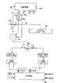
新方法SESP是在上述要求的意义上对偏转过程的校正的总的延续。它提供了一种适于将现有方法与稍后的扩展相组合的结构。图35示出SESP的结构。The new method SESP is a general continuation of the correction of the deflection process in the sense of the above requirements. It provides a structure suitable for combining existing methods with later extensions. Fig. 35 shows the structure of SESP.
SESP设计成标准AYC功能的补充。由此,SESP一方面可使用AYC的参量及机构。另一方面,AYC无障碍地在幕后继续工作并且当SESP不能适当地使车辆稳定时如惯常的那样进行干涉。如果标准AYC进行干涉,则SESP控制被禁止或者运行中的SESP控制被中断。这样的中断可迅速地或(较舒适地)通过适度地降低SESP调节参量实现,图35。SESP is designed to complement the standard AYC functionality. Thus, on the one hand, SESP can use the parameters and mechanisms of AYC. AYC, on the other hand, continues to work unimpeded behind the scenes and intervenes as usual when SESP fails to properly stabilize the vehicle. If the standard AYC intervenes, SESP control is disabled or running SESP control is interrupted. Such an interruption can be effected quickly or (more comfortably) by a moderate reduction of the SESP control variable, FIG. 35 .
下面简要说明SESP的各个部件。The various components of the SESP are briefly described below.
行驶状况识别系统使用关于驾驶员请求(例如方向盘转角、发动机力矩需求、制动压力)及当前的车辆状态(例如横向加速度、所估计的弯道半径、速度)的信息来判定是否存在潜在的偏转状况。该识别系统构造成状态自动装置。图30示例性地示出在当前的SESP实现中可能的状态及允许的状态过渡。通过使用状态自动装置保证了所识别的行驶状况的单义性。多个状态之间的区别是必须的,以便可使SESP控制器最佳地与当前的行驶状况相匹配。以并行的方式(例如借助于AYC状态、ABS状态、路面横向倾斜度、车速)持续地检验是否允许SESP干涉。在结果为否的情况下,立即分配“SESP无效”状态。有些偏转原因(例如载荷变化)固有地对车辆性能具有时间上有限的作用。在这些情况下在一定的时间之后离开SESP行驶状况识别系统中的相关的状态。对于这样的状态的时间限制的另一个理由是,驾驶员在一定的“匹配时间”之后通常本身可控制缓慢的偏转过程。Driving situation recognition uses information about driver requests (e.g. steering wheel angle, engine torque demand, brake pressure) and current vehicle state (e.g. lateral acceleration, estimated curve radius, speed) to determine if there is a potential yaw situation. The recognition system is designed as a status automatic device. Figure 30 exemplarily shows possible states and allowed state transitions in the current SESP implementation. The unambiguousness of the detected driving situation is ensured by the use of state automation. A distinction between states is necessary in order to optimally adapt the SESP controller to the current driving situation. Whether SESP intervention is permitted is checked continuously in parallel (for example with the aid of AYC status, ABS status, lateral gradient of the road surface, vehicle speed). In the case of a negative result, the "SESP invalid" status is assigned immediately. Some causes of deflection, such as load changes, inherently have a time-limited effect on vehicle performance. In these cases, the relevant state in the SESP driving situation detection system is exited after a certain period of time. Another reason for the time limitation of such a state is that the driver can usually control the slow deflection process himself after a certain "adaptation time".
如前文所述,使用行驶状况识别系统的已识别的状态启动SESP控制器并且使其参数最佳地与当前的行驶状况相匹配(例如控制阈值)。为了可以尽可能提早地“快速转换(scharf schalten)”灵敏的SESP控制器,SESP行驶状况识别系统不仅分析处理车辆反应,而且还分析处理导致该车辆反应的原因。除了影响控制器参数外,行驶状况识别系统的另一个目的是向基准信号形成单元指示何时应存储用于基准参量的偏移量校正的偏移量。这也已经在识别用于偏转状况的可能原因时发生。As mentioned above, the detected state of the driving situation detection system is used to activate the SESP controller and optimally adapt its parameters to the current driving situation (eg control thresholds). In order to be able to "quickly switch over" the sensitive SESP controller as early as possible, the SESP driving situation recognition system analyzes not only the vehicle reaction, but also the reasons for this vehicle reaction. In addition to influencing the controller parameters, another purpose of the driving situation detection system is to indicate to the reference signal formation unit when an offset for the offset correction of the reference variable should be stored. This also happens already when identifying possible causes for deflection conditions.
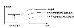
对于基准信号形成单元,SESP使用偏移量校正原理。驾驶员请求由SESP基准横摆角速度表示。与AYC基准横摆角速度相比,该SESP基准横摆角速度具有一偏移量,该偏移量刚好这样大,使得SESP横摆角速度偏差在载荷变化或制动干涉开始时为零。For the reference signal forming unit, SESP uses the principle of offset correction. The driver request is represented by the SESP reference yaw rate. Compared with the AYC reference yaw rate, the SESP reference yaw rate has an offset which is just large enough that the SESP yaw rate deviation is zero at the beginning of a load change or brake intervention.
由于该偏移量,一方面横摆角速度传感器的可能未被补偿的偏移量得到了补偿。这对于防止灵敏的SESP横摆角速度控制器的控制错误是必需的。另一方面,通过该偏移量补偿仅调整了与当前车辆性能的偏差。Due to this offset, on the one hand, a possibly uncompensated offset of the yaw rate sensor is compensated. This is necessary to prevent control errors of the sensitive SESP yaw rate controller. On the other hand, only deviations from the current vehicle behavior are adjusted by this offset compensation.
图31示出对于横摆角速度传感器偏移量为正的情况SESP基准横摆角速度的构成。FIG. 31 shows the configuration of the SESP reference yaw rate for the case where the yaw rate sensor offset is positive.
可根据使用情况选择SESP控制器的数量及类型。控制器的控制参量是横摆角速度,调节参量是附加横摆力矩。但也可容易地考虑到例如侧滑角速度的控制参量或附加的发动机力矩的调节参量。其他可能的调节参量(假如存在相应的执行机构)是:附加的转向角、弹簧/减振器特性的变化、前轴与后轴之间的发动机力矩分配的变化。横摆角速度控制器的目的是,由实际横摆角速度与SESP基准横摆角速度的偏差计算对于车辆稳定必需的附加横摆力矩。The number and type of SESP controllers can be selected according to the usage. The control parameter of the controller is the yaw rate, and the adjustment parameter is the additional yaw moment. However, control variables such as the yaw rate or additional control variables of the engine torque can also easily be taken into account. Other possible control variables (provided corresponding actuators are available) are: additional steering angle, changes in spring/damper properties, changes in the distribution of engine torque between the front and rear axles. The purpose of the yaw rate controller is to calculate the additional yaw moment necessary for vehicle stability from the deviation of the actual yaw rate from the SESP reference yaw rate.
构造成纯粹的比例控制器的控制器除了存在允许的行驶状况外还具有作为启动准则的用于SESP横摆角速度偏差的阈值。该阈值视行驶状况而定至多是标准AYC控制器中的阈值的一半,参见图33。对于“弯道中的载荷变化”这种状况,使用不同的阈值。A controller designed as a purely proportional controller has, in addition to the permissible driving situation, a threshold value for the SESP yaw rate deviation as an activation criterion. Depending on the driving situation, this threshold is at most half of the threshold in the standard AYC controller, see FIG. 33 . For the case "Load change in a bend", a different threshold is used.
在SESP模块“仲裁装置”中,SESP控制器的所有同类的调节参量(例如附加横摆力矩)根据确定的优先法则被组合。这些优先法则的选择又可取决于使用情况。反向的请求的取最大值、相加及抑制是这些法则的公知的例子。仲裁装置的其他目的是使SESP调节参量与(尤其是标准AYC的)其他控制器的需求相协调并且在必要时保证“平滑的”过渡。In the SESP module "Arbitrator", all homogeneous manipulated variables of the SESP controller (eg additional yaw moment) are combined according to a defined priority law. The choice of these priority rules may in turn depend on the use case. Maximization, addition and suppression of reverse requests are well known examples of these laws. Another purpose of the arbitration device is to adapt the SESP control variable to the requirements of other controllers (in particular of standard AYC) and to ensure a “smooth” transition if necessary.
在最后的步骤中转换这些调节参量。在此情况下必须注意的是,驾驶员尽可能不会觉察SESP干涉。这还包括,驾驶员不会从这种组合仪器接收到任何关于SESP干涉的信息。在此情况下,在这个步骤中共同使用ESP控制器的标准机构。通过接口将SESP期望的策略传输给这些机构。These control variables are converted in a final step. In this case, care must be taken that the driver is as unaware of SESP interventions as possible. This also includes that the driver does not receive any information about SESP intervention from this instrument combination. In this case, the standard mechanism of the ESP controller is commonly used in this step. The policies desired by the SESP are communicated to these agencies through the interface.
下面将参照图32示例性地描述附加横摆力矩在当前的SESP实现中的应用。首先检验是否驾驶员用最小压力制动。如果是,则通过弯道内侧的后轮上的压力衰减实现附加横摆力矩。这种干涉是舒适的,因为它一方面相对于主动的压力建立以强地降低的阀及泵活动性来进行,另一方面,通过后轴上的干涉避免了通过转向系统引起的反作用。此外,通过提高弯道内侧的后轮的侧向力潜能有利于车辆的横向稳定性。在需要时,附加地在弯道内侧的前轮上衰减压力。如果驾驶员的制动压力低于开始所述的最小压力,则通过弯道外侧的后轮上的压力增加并且在必要时附加地通过弯道外侧的前轮上的压力增加实现所述附加的横摆力矩。为了保持相关车轮的侧向力潜能,压力(通过使用已经存在的“滑移率监测器”)被向上限制到车轮与路面之间的最大纵向力的水平。为了在任何情况下都不超过该压力水平,将ABS控制器转置到一个灵敏的模式中以保证双重可靠性。同时,EBV控制器被禁用以便避免不期望的压力限制。为了保证SESP压力增加模式的舒适性,借助于已经存在的低噪声方法“EUV截止阀控制”调节车轮压力。The application of the additional yaw moment in the current SESP implementation will be exemplarily described below with reference to FIG. 32 . It is first checked whether the driver brakes with minimum pressure. If so, an additional yaw moment is achieved by the pressure damping on the rear wheel on the inside of the bend. This intervention is convenient because on the one hand it takes place with a strongly reduced valve and pump activity compared to an active pressure build-up, and on the other hand a reaction by the steering system is avoided by the intervention on the rear axle. Furthermore, the lateral stability of the vehicle is favored by increasing the lateral force potential of the rear wheels on the inside of the bend. When required, the pressure is additionally damped on the front wheel on the inside of the bend. If the driver's brake pressure falls below the minimum pressure mentioned at the outset, the additional pressure is achieved by increasing the pressure on the rear wheel on the outside of the curve and, if necessary, by increasing the pressure on the front wheel on the outside of the curve. yaw moment. In order to preserve the lateral force potential of the relevant wheel, the pressure (by using the already existing "slip rate monitor") is limited upwards to the level of the maximum longitudinal force between the wheel and the road surface. In order not to exceed this pressure level under any circumstances, the ABS controller is switched into a sensitive mode for double reliability. At the same time, the EBV controller is disabled in order to avoid undesired pressure limitation. In order to ensure comfort in the SESP pressure boost mode, the wheel pressure is regulated by means of the already existing low-noise method "EUV shut-off valve control".
为了在路面摩擦系数低的情况下减小由于主动的压力建立造成的后轴不稳定性的危险,本发明提出,从弯道外侧的后轮分配到弯道外侧的前轮上的压力越大,所估计的路面摩擦系数越小。此外有利的可以是,以首先使用压力衰减的潜能的方式选择一个流畅的过渡来取代压力减小模式与压力增加模式之间的这种“二元的”判定。附加横摆力矩的此后可能还未考虑的部分则以上述方式通过压力增加实现在可供使用的纵向力潜能的限度内。该部分在纯粹的“二元的”判定的情况下不予考虑,图32。In order to reduce the risk of rear axle instability due to active pressure build-up in the case of a low coefficient of friction on the road surface, the invention proposes that the greater the pressure distributed from the rear wheel on the outside of the curve to the front wheel on the outside of the curve , the estimated road surface friction coefficient is smaller. Furthermore, it may be advantageous to select a smooth transition by initially using the potential for pressure decay instead of this “binary” decision between pressure reduction mode and pressure increase mode. The portion of the additional yaw moment that may not yet be considered is then brought about within the limits of the available longitudinal force potential by the pressure increase in the manner described above. This part is not considered in the case of a purely "binary" decision, FIG. 32 .
一旦在ESP控制器中车辆是否具有拖车的信息可供使用,则提出对于SESP使用该信息以便由SESP干涉(如压力建立)产生的车辆纵向减速度被限制到不使该拖车不稳定的水平。在最简单的情况下可在检测到有拖车时例如完全抑制SESP压力建立。Once information is available in the ESP controller whether the vehicle has a trailer or not, it is proposed to use this information for SESP so that vehicle longitudinal deceleration resulting from SESP intervention (eg pressure build-up) is limited to a level that does not destabilize the trailer. In the simplest case it is possible, for example, to completely suppress the SESP pressure build-up when a trailer is detected.
为了实现调节参量,还应理解,在对于一个调节参量存在多个执行机构的情况下,需要将该调节参量按比例分配给这些执行机构。作为分配准则可考虑例如舒适性及效力。例如可根据下面的原理考虑反应时间准则。首先将该调节参量完整地传输给反应最快速的执行机构。不能被该执行机构实现的份额则传输给第二快速的执行机构,等等。利用该原理获得最短的总反应时间。In order to realize the manipulated variable, it should also be understood that, in the case of a plurality of actuators for a manipulated variable, it is necessary to distribute the manipulated variable proportionally to these actuators. As dispensing criteria, for example, comfort and potency can be taken into account. For example, the reaction time criterion can be considered according to the following principle. The manipulated variable is first transmitted completely to the fastest-responsive actuator. The shares that cannot be fulfilled by this executive body are transferred to the second fastest executive body, etc. This principle is used to obtain the shortest overall reaction time.
此外还应理解,为了符合附加横摆力矩,首先检验是否驾驶员用例如20bar的最小压力制动。如果是,则该附加横摆力矩通过弯道内侧的后轮上的(及必要时弯道内侧的前轮上的)舒适的压力衰减实现。Furthermore, it should be understood that in order to comply with the additional yaw moment, it is first checked whether the driver brakes with a minimum pressure of, for example, 20 bar. If so, this additional yaw moment is achieved by a comfortable pressure damping on the rear wheel (and possibly the front wheel on the inside of the curve) on the inside of the curve.
如果驾驶员的制动压力低于开始所述的最小压力,则总的附加横摆力矩通过弯道外侧的后轮上的压力建立实现。为了保持相关车轮的侧向力潜能,压力(通过使用已经存在的“滑移率监测器”)被向上限制到车轮与路面之间的最大纵向力的水平。为了在任何情况下都不超过该压力水平,将ABS控制器转置到一个灵敏的模式中以保证双重可靠性。同时,EBV控制器被禁用以便避免不期望的压力限制。If the driver's brake pressure falls below the minimum pressure mentioned at the outset, the total additional yaw moment is achieved by the pressure build-up on the rear wheel on the outside of the curve. In order to preserve the lateral force potential of the relevant wheel, the pressure (by using the already existing "slip rate monitor") is limited upwards to the level of the maximum longitudinal force between the wheel and the road surface. In order not to exceed this pressure level under any circumstances, the ABS controller is switched into a sensitive mode for double reliability. At the same time, the EBV controller is disabled in order to avoid undesired pressure limitation.
为了即使在压力增加模式中也保证SESP的舒适性,在该模式中借助于已经存在的低噪声方法“EUV截止阀控制”调节车轮压力。In order to ensure SESP comfort even in pressure boost mode, the wheel pressure is regulated in this mode by means of the already existing low-noise method "EUV shut-off valve control".
图33用左转弯的例子表明:SESP在哪些车轮上进行压力衰减(-)及压力增加(+)。Figure 33 shows, with the example of a left turn, on which wheels the SESP performs a pressure decay (-) and a pressure increase (+).
新方法SESP的优点Advantages of the new method SESP
新方法SESP相对于现有方法具有下列优点:Compared with existing methods, the new method SESP has the following advantages:
1)SESP的结构允许组合现有的方法以得到具有较大作用范围的总体方法,这些现有的方法单独使用时仅覆盖很小的作用范围。1) The structure of SESP allows the combination of existing methods to obtain an overall method with a large range of action, which when used alone only cover a small range of action.
2)SESP的结构对于扩展是开放的。可根据需要添加新的状况、控制参量及调节参量。因此SESP的结构具有处理在可供使用的传感系统及执行机构的限度内缓慢的转弯过程的潜力。2) The structure of SESP is open to extension. New conditions, control parameters and adjustment parameters can be added as required. The SESP architecture therefore has the potential to handle slow cornering processes within the limits of available sensing systems and actuators.
3)通过控制器部分模块与所述行驶状况识别系统的调节参量实现的明确的分离,对于不同的行驶状况可使用相同的作用机构。这保证了连贯的控制品质并且简化了SESP的应用及进一步开发。3) Due to the unambiguous separation of the controller submodules from the control variables of the driving situation detection system, the same mechanism of action can be used for different driving situations. This ensures consistent control quality and simplifies the application and further development of the SESP.
4)与“侧滑角控制”的基于模型的方法相比,SESP在其作用范围的限度内不依赖于附加的传感器(如单个车轮力传感器或车轮制动压力传感器)。传统的ESP传感器即足够。4) In contrast to the model-based method of "Sideslip Angle Control", SESP does not rely on additional sensors (such as individual wheel force sensors or wheel brake pressure sensors) within the limits of its range of action. A conventional ESP sensor is sufficient.
5)通过连续地分析处理在时间上初期的偏转原因并且通过仅选择性地启动控制器,SESP可使用较灵敏的控制阈值。这使得SESP相对于标准AYC一方面能够识别缓慢的偏转过程,另一方面能够用较少的调节能量提早校正这种偏转过程。5) By continuously evaluating the cause of deflection early in time and by only selectively activating the controller, SESP can use more sensitive control thresholds. This enables SESP to detect slow deflection processes on the one hand and, on the other hand, to correct such deflection processes earlier with less adjustment energy compared to standard AYC.
6)通过使用各自的SESP控制器,标准AYC控制器可在幕后继续运行并且持续地检验SESP的稳定作用是否足够。如果情况不是这样,则AYC如惯常的那样进行干涉。6) By using the respective SESP controller, the standard AYC controller can continue to run in the background and continuously check whether the stabilization effect of the SESP is sufficient. If this is not the case, AYC intervenes as usual.
7)所述被偏移量校正的基准参量的连续使用,降低了信号误差的干扰影响。7) The continuous use of the reference parameter corrected by the offset reduces the interference influence of the signal error.
8)所提出的用于实现附加横摆力矩的策略不仅在压力衰减模式中而且在压力增加模式中都提供了高的舒适性。该策略还一贯地设计成保持车辆稳定性。8) The proposed strategy for achieving the additional yaw moment provides high comfort not only in the pressure decay mode but also in the pressure increase mode. The strategy is also consistently designed to maintain vehicle stability.
通过行驶状况识别、控制与调节参量的实现之间明确的分离获得显著的改善。SESP以这种方式组合了现有的方法,优化了这些现有的方法,并且对于以后的扩展是开放的。由此,SESP能够在无附加的传感装置或执行机构的情况下显著地扩展ESP控制器的作用范围。Significant improvements are achieved through the clear separation between driving situation detection, control and realization of the regulated variables. In this way SESP combines existing approaches, optimizes them, and is open to future extensions. The SESP thus makes it possible to significantly extend the range of action of the ESP controller without additional sensors or actuators.
附图说明Description of drawings
图1是行驶稳定性控制系统的总体结构的框图;FIG. 1 is a block diagram of an overall structure of a driving stability control system;
图2是横摆力矩控制器的结构的框图;Fig. 2 is a block diagram of the structure of the yaw moment controller;
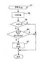
图3是检测行驶状况如弯道行驶的流程图;Fig. 3 is a flow chart of detecting driving conditions such as curve driving;
图4及图5分别是关于确定路面摩擦系数的流程图,其中图5应被嵌入图4中;Fig. 4 and Fig. 5 are flow charts about determining the road surface friction coefficient respectively, wherein Fig. 5 should be embedded in Fig. 4;
图6及图8是用于以不同的表示方式确定侧滑角速度及侧滑角的当前值的组合方法的框图;6 and 8 are block diagrams of combined methods for determining current values of sideslip angular velocity and sideslip angle in different representations;
图7是用于由运动学的观察直接确定侧滑角速度的框图,作为图6的组合方法的一部分;FIG. 7 is a block diagram for directly determining sideslip angular velocity from kinematic observations, as part of the combined method of FIG. 6;
图9是稳定性控制的控制电路,车辆的计算模型根据行驶速度而变化;Figure 9 is a control circuit for stability control, the calculation model of the vehicle changes according to the driving speed;
图10及图11是表示车辆的侧偏角之差与各个车轮的侧滑角及速度矢量的关系的图;10 and 11 are diagrams showing the relationship between the difference in the slip angle of the vehicle and the sideslip angle and the velocity vector of each wheel;
图12至图15是用于控制行驶稳定性的控制电路的框图,其中,在比较器中相互比较的参量是横摆角速度的导数;12 to 15 are block diagrams of control circuits for controlling driving stability, wherein the parameters compared with each other in the comparator are derivatives of the yaw rate;
图16是用于确定行驶稳定性的控制电路,其中,采用车辆制动器的压力梯度和/或阀转换时刻作为控制参量;FIG. 16 is a control circuit for determining driving stability, wherein the pressure gradient of the vehicle brake and/or the switching time of the valve are used as control parameters;
图17是用于说明用于计算附加横摆力矩的控制器的框图;FIG. 17 is a block diagram for explaining a controller for calculating an additional yaw moment;
图18是用于说明低通滤波器的框图;FIG. 18 is a block diagram for explaining a low-pass filter;
图19是用于计算被校正的额定横摆角速度的流程图;Fig. 19 is a flowchart for calculating the corrected rated yaw rate;
图20是计算被校正的附加横摆力矩的框图;Figure 20 is a block diagram for calculating the corrected additional yaw moment;
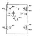
图21是机动车的示意图;Figure 21 is a schematic diagram of a motor vehicle;
图22是用于说明分配逻辑电路的框图;Fig. 22 is a block diagram for explaining distribution logic circuit;
图23是方向盘被转动时的机动车及所作用的力的示意图;Fig. 23 is a schematic diagram of the motor vehicle and the applied force when the steering wheel is turned;
图24是用于说明侧向力系数及纵向力系数与车轮滑移率之间的关系的曲线图;Fig. 24 is a graph for illustrating the relationship between the lateral force coefficient and the longitudinal force coefficient and the wheel slip ratio;
图25a、b是用于说明不足转向及过度转向特性的机动车的示意图;Figure 25a, b is a schematic diagram of a motor vehicle used to illustrate understeer and oversteer characteristics;
图26是分配逻辑电路内部的决策逻辑电路的流程图;Fig. 26 is a flowchart of the decision logic circuit inside the distribution logic circuit;
图27是用于计算进入阀及排出阀的转换时间的框图;Figure 27 is a block diagram for calculating switching times for inlet and outlet valves;
图28是用于说明一次计算内的时间间隔的图;FIG. 28 is a diagram for explaining time intervals within one calculation;
图29是用于确定车轮制动压力的原理框图;Figure 29 is a functional block diagram for determining wheel brake pressure;
图30是行驶状况识别系统的原理框图;Fig. 30 is a functional block diagram of the driving condition recognition system;
图31a、b示出对于横摆角速度传感器偏移量为正的情况SESP基准横摆角速度的构成;Figure 31a, b show the composition of the SESP reference yaw rate for the case where the yaw rate sensor offset is positive;
图32a、b示出附加横摆力矩在当前SESP实现中的应用;Figure 32a,b show the application of additional yaw moments in the current SESP implementation;
图33用左转弯的例子表明SESP在哪些车轮上进行压力衰减(-)及压力增加(+);Figure 33 uses the example of a left turn to show on which wheels SESP performs pressure decay (-) and pressure increase (+);
图34示出如何降低SESP错误控制的风险;Figure 34 shows how to reduce the risk of SESP wrong control;
图35示出SESP的结构。Fig. 35 shows the structure of SESP.
具体实施方式Detailed ways
现在参照图1概括地说明行驶稳定性控制(FSR)的过程。The process of the driving stability control (FSR) will now be described in outline with reference to FIG. 1 .
车辆1构成所谓的控制对象。The
由驾驶员给出的参量,即,驾驶员制动压力P驾驶员或PTHZ、节气门踏板位置、档位信息及转向角δ,作用在车辆1上。在车辆1上测量由此引起的参量,即,发动机实际力矩MMotist、横向加速度aquer、横摆角速度
车轮转速输入给防抱死系统7、驱动防滑控制系统8、电子制动力分配系统9及灵敏的横摆力矩控制系统20的控制器。驱动防滑控制系统的控制器8还附加地获得当前的发动机力矩的数据,即发动机实际力矩MMotist。该信息也输送给横摆力矩控制系统GMR的控制器10及灵敏的横摆力矩控制系统SESP的控制器20。SESP的控制器还附加地获得换档信息。此外,这些控制器还由传感器获得关于车辆的横向加速度aquer及横摆角速度
FSR的所有五个电子控制器,即SESP 20、GMR 10、ABS 7、ASR 8及EBV 9的控制器,平行工作且不相关地根据各自的控制策略彼此无关地处理用于各个车轮的制动压力预给定值PSESP、PGMR、PABS、PASR、PEBV。All five electronic controllers of FSR, namely the controllers of
此外,由ASR控制器8和GMR控制器10及SESP控制器平行地计算出发动机力矩的预给定值MASR及MStellM。In addition, engine torque presets MASR and MStellM are calculated in parallel by the
GMR控制器10及SESP控制器20如下确定各个车轮制动压力的压力预给定值PGMR及PSESP:The
GMR控制器10及SESP控制器20首先分别计算附加横摆力矩MGGMR或MGSESP,如果该附加横摆力矩MGGMR或MGSESP通过相应的制动操作产生,则它使得弯道内的行驶状态稳定或弯道内的及直线行驶时的行驶性能改善。所述MGGMR或MGSESP分别输入给分配逻辑电路2或21,该分配逻辑电路2或21也可分别作为GMR控制10或SESP控制20的一部分来表示。此外,可能存在的借助于驾驶员制动压力P驾驶员(=PTHZ)被识别的驾驶员对车辆减速的请求也输入分配逻辑电路2或21中。分配逻辑电路2或21由预给定的横摆力矩MGGMR或MGSESP以及所期望的驾驶员制动压力计算车轮制动器的横摆力矩控制制动压力PGMR或PSESP,该数值对于不同的车轮可能有很大差别。为了功能最优化,横摆力矩控制制动压力PGMR或PSESP与由其余的ABS控制器7、ASR控制器8及EBV控制器9所计算的压力预给定值一起被输入到用于车轮制动压力的优先电路3。该优先电路3在考虑驾驶员请求的情况下确定用于最佳行驶稳定性或用于最佳行驶性能的额定车轮压力PSoll。这些额定车轮压力可以对应于这五个控制器中一个的压力预给定值,或者表示它们的叠加。The
可用与确定车轮制动压力相似的方法确定发动机力矩。ABS及EBV仅对车轮制动器产生影响,而在SESP、GMR及ASR中还对发动机力矩起作用。在SESP控制器20、GMR控制器10及ASR控制器8中单独地计算的发动机力矩的预给定值MSESP、MStellM及MASR在优先电路4中被分析处理并且叠加得到额定力矩。但该额定力矩MSoll也可仅相应于上述三个控制器中的一个所计算的预给定值。Engine torque can be determined in a similar way to wheel brake pressure. ABS and EBV only affect the wheel brakes, while SESP, GMR and ASR also affect the engine torque. The engine torque presets MSESP , MStellM and MASR calculated individually in the
基于所计算的车轮制动压力的额定值PSoll及发动机力矩的额定值MSoll,可通过制动及发动机干涉进行行驶性能的行驶稳定性控制和/或改善。为此,表示实际的车轮制动压力的液压信号或数值也输入压力控制单元5中。该压力控制单元5由此产生阀信号,这些阀信号输出给车辆1中的各个车轮制动器的控制阀。发动机管理系统6根据MSoll控制车辆的驱动发动机,由此又产生改变的发动机力矩。由此分别得到用于FSR系统的五个电子控制器7、8、9、10及20的新的输入参量。Based on the calculated setpoint value PSoll for the wheel brake pressure and the setpoint value MSoll for the engine torque, driving stability control and/or improvement of the driving behavior can be carried out by braking and engine intervention. For this purpose, hydraulic signals or values representing the actual wheel brake pressures are also fed into the
2.具有灵敏的横摆力矩控制器(SESP)的横摆力矩控制器(GMR)的结构2. Structure of Yaw Moment Controller (GMR) with Sensitive Yaw Moment Controller (SESP)
图2在框图中示出,如何在GMR控制器10及灵敏的横摆力矩控制器20内确定用于分配逻辑电路2及21的附加横摆力矩MG及MGSESP。为此,作为输入参量输入转向角δ、来自ABS控制器7的车辆参考速度vRef、所测得的横向加速度aquer以及所测得的横摆角速度
如果假定当经滤波的车辆参考速度vRef Fil取其恒定的最小值时车辆处于静止状态,则也可取消通过启动逻辑电路11直接检测车辆参考速度vRef。If it is assumed that the vehicle is at a standstill when the filtered vehicle reference speed vRef Fil assumes its constant minimum value, direct detection of the vehicle reference speed vRef by the activation logic circuit 11 can also be dispensed with.
在GMR控制器中存储有车辆参考模型12,该车辆参考模型基于转向角δ、经滤波的车辆参考速度vRef Fil及所测得的横摆角速度

为了将这些预给定值保持在物理上可能的范围中,对于这些计算还需要路面摩擦系数μ,该路面摩擦系数在摩擦系数及状况识别系统13中作为估计值
摩擦系数及状况识别系统13为了其计算而使用所述经滤波的参考速度vRef Fil、所测得的车辆横向加速度aquer、所测得的横摆角速度


摩擦系数及状况识别系统13的输出信号输入给SESP状况识别系统22,该SESP状况识别系统基于GMR控制器10的所识别的行驶状况及关于驾驶员请求(δ,MMot ist,PTHZ,档位信息)和当前行驶状态(vwheel,aquer,vref,13)的信息来判断是否存在潜在的与驾驶员所期望的路线的偏离(车辆绕垂直轴的转动状态,尤其是偏转状况)。在这种情况下至少转向角δ、发动机力矩要求MMotist及驾驶员制动压力P驾驶员输入到驾驶员期望识别系统中,而至少由
在行驶状况识别系统22中识别的状态触发SESP控制规则单元23的启动并且使得参数(例如控制阈值)与当前的行驶状况的最佳匹配。行驶状况识别系统22为此分析处理车辆反应之前的原因,如PTHZ、换档信息、发动机力矩信息,以便提前启动灵敏的SESP控制规则单元23。除了影响SESP控制器参数外,行驶状况识别系统22还具有这样的任务,即向基准信号形成装置24指示何时应存储用于基准参量的偏移量校正的偏移量。这也已经在识别到用于车辆的偏转状况的可能原因时发生。The states detected in the driving
最后,基于经滤波的车辆参考速度vRef Fil、所测得的车辆横向加速度aquer以及所测得的横摆角速度

为了除去在侧滑角急剧变化时的峰值,侧滑角速度的计算值通过一阶低通滤波器15,该滤波器将侧滑角速度的估计值


程序16及SESP控制器20持续地工作,以便总是随时准备好当前的控制参量。但这些控制力矩是否传送给图1及图2中所示的分配逻辑电路2、21则取决于启动逻辑电路11、25。The
GMR控制器10的启动逻辑电路11不仅接收未经滤波的车辆参考速度vRef以及如上所述的侧滑角速度

如果车辆处于倒车状态,则中断MG的传递。如果识别到车辆处于静止状态,或者所估计的侧滑角速度

SESP控制器20的启动逻辑电路25不仅接收SESP基准信号形成装置24及启动逻辑电路11的值,而且接收额定横摆角速度


如果车辆没有处于所确定的状态之一中,或者在遵守确定的条件的情况下GMR控制器10或ABS控制器7、ASR控制器8的状态与这些确定的状态相叠加,则中断MGSESP的传递。如果识别到车辆处于静止状态,或者所估计的侧滑角速度

2.1GMR控制器10的摩擦系数及状况识别系统2.1 Friction coefficient and status recognition system of
图3、4及5中以流程图的形式示出摩擦系数及状况识别系统13中的逻辑流程。The logic flow in the friction coefficient and
图3的对象是状况识别。通过所示出的流程可区别八个不同的行驶状况:The object of Figure 3 is situation recognition. Eight different driving situations can be distinguished by the sequence shown:
<0>车辆静止<0> The vehicle is stationary
<1>匀速直线行驶<1> Driving in a straight line at a constant speed
<2>加速直线行驶<2> Accelerate and drive in a straight line
<3>减速直线行驶<3> Slow down and drive straight
<6>倒车<6> reversing
<7>匀速弯道行驶<7> Driving on a curve at a constant speed
<8>加速弯道行驶<8> Accelerate on a curve
<9>加速弯道行驶<9> Accelerate on a curve
在该流程图中逻辑分支表示为菱形。Logical branches are represented as diamonds in this flowchart.
从给定的待确定的状况51起,首先在菱形52中判断车辆是否处于静止状态。如果经滤波的车辆参考速度vRef Fil取其最小值,则认为车辆处于静止状态,即状况<0>。如果vRef Fil大于vmin,则在菱形53中询问前面执行的状况识别的结果。Starting from a given
如果先前所确定的状况被识别为倒车,即状况<6>,则车辆继续处于倒车状态,因为在此期间没有识别出车辆静止状态。否则在此期间在菱形52中应识别出状况<0>。If the previously determined situation is identified as reversing, ie situation <6>, the vehicle continues to be in the reversing state, since no vehicle standstill was recognized during this period. Otherwise, the situation <0> should be detected in
如果前面执行状况识别的结果不是状况<6>,则在菱形54询问横向加速度aquer的绝对值。如果该值小于一确定的阈值aquermin,则认为车辆是直线行驶,即处于状况<1>至<3>之一。If the result of the previously performed situation identification is not situation <6>, the absolute value of the lateral acceleration aquer is queried at
如果虽然所测得的横向加速度aquer的绝对值大于阈值aquermin,但在菱形55中在下一步骤中识别到转向角δ的绝对值小于一阈值δmin,则同样认为车辆是直线行驶。在这种情况下所测得的横向加速度aquer存在测量误差,导致该误差的原因在于,横向加速度测量仪通常固定地装配在车辆横向轴线上并且在路面倾斜的情况下与车辆一起倾斜,从而指示一个实际上并不存在的横向加速度。If, although the absolute value of the measured transverse acceleration aquer is greater than the threshold value aquermin , it is detected in a next step in
如果车辆处于直线行驶状态,则在菱形59中考察纵向加速度along的大小。如果该纵向加速度的绝对值小于一阈值alongmin,则认为是匀速直线行驶。但如果该纵向加速度along的绝对值大于该阈值,则在菱形60中区别是正的纵向加速度还是负的纵向加速度。如果along的值大于该阈值alongmin,则车辆处于加速直线行驶状态,即处于状况<2>。如果along的值小于该阈值alongmin,则这只能意味着纵向加速度为负值,即车辆处于减速直线行驶状态,即状况<3>。If the vehicle is traveling straight ahead, the magnitude of the longitudinal acceleration along is examined in
如果不存在状况<0>至<3>并且在菱形55中识别到转向角δ的绝对值大于阈值δmin,则在菱形56中询问车辆在此期间是否向后行驶。倒车的识别只有在此是必需的,因为在直线行驶中横摆角速度
如上所述,通过将所测得的横摆角速度


如果不满足倒车行驶的条件,则存在向前方向上的弯道行驶。该弯道行驶是否匀速则在菱形57中检验。如前面在直线行驶情况下在菱形59及60中已述的那样,在菱形57中首先考察纵向加速度along的大小。如果该值小于阈值alongmin,则是匀速弯道行驶,即状况<7>。如果纵向加速度along的绝对值大于阈值alongmin,则在菱形58中进一步判断纵向加速度along是正还是负。在纵向加速度along是正的情况下,车辆处于加速弯道行驶中,即状况<8>,而在纵向加速度along为负的情况下,识别到减速弯道行驶,相应于状况<9>。If the conditions for reverse travel are not fulfilled, there is a curve travel in the forward direction. Whether the curve travels at a constant speed is checked in
可采用不同的方式确定纵向加速度along。例如可由ABS控制器7所提供的参考速度vRef确定纵向加速度,在这种情况下应考虑这样的参考速度vRef在ABS干涉期间可能偏离实际的车辆速度。因此对于ABS情况需进行vRef的校正。如果在ABS控制器中进行这样的计算,则在特定情况下也可直接由该ABS控制器获得纵向加速度along。The longitudinal acceleration along can be determined in different ways. For example, the longitudinal acceleration can be determined from a reference speed vRef provided by the
根据图3的状况识别持续地重复地执行,其中上一次确定的状况被存储以便在菱形53中供使用。The situation recognition according to FIG. 3 is carried out continuously and repeatedly, wherein the last determined situation is stored for use in
图4及图5中示出用于确定路面摩擦系数的可能流程。只有当横摆力矩控制器进入控制时才进行摩擦系数确定。但因为在控制开始时还不存在估计出的摩擦系数,所以开始控制时设定摩擦系数μ=1。A possible procedure for determining the coefficient of friction of the road surface is shown in FIGS. 4 and 5 . The friction coefficient determination is only carried out when the yaw moment controller is in control. However, since the estimated friction coefficient does not yet exist at the start of the control, the friction coefficient μ=1 is set at the start of the control.
根据瞬时行驶状况进行横摆力矩控制的出发点在于,车辆至少处于不稳定的行驶状况的边界区域附近。由此可通过考察车辆上的当前的测量值来推断瞬时的路面摩擦系数。于是在开始控制时所确定的摩擦系数在进一步的过程中用作用于限制额定横摆角速度


为此首先由所测得的横向加速度aquer及所计算出的纵向加速度along的值计算内摩擦系数


在某些状况中也可不进行所估计的摩擦系数


以这种方式计算的摩擦系数通常是所有四个车辆车轮的平均摩擦系数。不能通过这种方式确定单个车轮的摩擦系数。The coefficient of friction calculated in this way is usually the average coefficient of friction of all four vehicle wheels. The coefficient of friction of individual wheels cannot be determined in this way.
现在结合图4说明确定摩擦系数的方法。在每个行驶状况中,根据域61在车辆状态中考虑当前的路面摩擦系数。为了确定相应的路面摩擦系数,首先根据步骤62对所测得的横向加速度aquer进行滤波。即,使所测得的值平滑,或者使曲线通过低通滤波器,使得不出现尖峰。步骤63包括根据图3的状况识别。所识别出的状况可用于随后的步骤74中的更新阶段。在菱形64中询问是否有必要进行控制干涉。起始摩擦系数μ=1首先作为这样的计算的基础。如果认为有必要进行控制,则在菱形65中询问这是否也是先前执行摩擦系数确定结束时的状态。对于涉及控制开始的情况,以前没有识别到控制,因此在步骤67中首次确定内摩擦系数
F2.1F2.1
在此g为重力常数,g=9.81m/s2。Here g is the gravitational constant, g=9.81m/s2 .
接着在步骤68中将用于步骤65的参数regold设置为1。此外,对应于内摩擦系数


因此,在下次进行摩擦系数确定时,假定行驶状况未改变,则在菱形65中将得出regold=1。在此在后面的过程中也确定一个


如果在执行中在菱形64中确定不需控制,则接着在菱形71中询问用于控制的参数regold上次是被设置为1还是0。如果该参数在上次执行中被设置为1,则在菱形72中询问执行的数量Tμ。如果在上次执行中进行了控制,则Tμ取值为1。如果仅仅在上上次执行中进行控制,则Tμ=2,依此类推。只要在步骤72中Tμ尚未达到一个确定的TμEnd,就一直在步骤73中将它增加1并且在步骤74中进行内摩擦系数

如果之后在下次的执行中在菱形64中又识别到无需控制,则在菱形71中regold=0,在域76中保持摩擦系数
图5中示出根据步骤74的用于更新内摩擦系数的判据。基于在域77中需要更新内摩擦系数,在步骤78中形成以前形成的估计的摩擦系数或
如果之后在菱形79中识别到车辆既不处于静止状态也不是直线行驶,即存在状况<6>至<9>之一,则在步骤80中分析处理步骤78中得出的结果。如上所述,只有当下降的摩擦系数不是由于转向操作所致时,才进行摩擦系数确定。如果车辆处于向前或向后的直线行驶状态或静止状态,或者估计的摩擦系数
2.1.1SESP状况识别系统2.1.1 SESP status recognition system
SESP状况识别系统22设计成状态自动装置。该状态自动装置借助于属性值(输入信号)的量来识别车辆的状态(行驶状况)。状态图显示在何事件下车辆从一个确定的状态过渡到相邻的状态。后继状态取决于初始状态及出现的事件。图30作为示例示出载荷变化的弯道行驶31、部分制动的弯道行驶32、部分制动的直线行驶33以及载荷变化的直线行驶34这些可能的状态以及SESP状况识别系统22中允许的状态过渡。使用状态自动装置保证了所识别的行驶状况的单义性。为了使用于实现SESP横摆力矩控制规则的程序23最佳地与当前的行驶状况相匹配,区别多个状态是必需的。在SESP状况识别系统22中确定对于计算SESP行驶状况状态31至34有关的所有的行驶状况。为此,状况识别系统22确定随后的行驶状况,该行驶状况之后可用作状态自动装置22.1中的输入信息。The SESP
稳态的直线行驶Steady-state driving in a straight line
SESP状况识别系统22确定驾驶员是否要直线行驶并且是否在此情况下使用通过摩擦系数及状况识别系统13检测的行驶状况<1>、<2>及<3>以及转向角δ即驾驶员的转向输入。结果被储存在标志位Sesp_straight_ahead中。The SESP
如果下面所有条件都被满足,则标志位Sesp_straight_ahead被设定为真:The flag bit Sesp_straight_ahead is set to true if all of the following conditions are met:
i.来自13的行驶状况是<1>、<2>或<3>i. The driving condition from 13 is <1>, <2> or <3>
ii.转向角的绝对值|δ|<阈值k1ii. Absolute value of steering angle |δ|<threshold k1
iii.转向角速度的绝对值
否则,标志位Sesp_straight_ahead被设定为伪。Otherwise, the flag bit Sesp_straight_ahead is set to false.
稳态的弯道行驶Steady curve driving
SESP状况识别系统22确定驾驶员是否要在持续弯道上行驶并且是否在此情况下使用通过摩擦系数及状况识别系统13检测的行驶状况<7>、<8>及<9>、横向加速度、驾驶员的转向输入δ、以及在摩擦系数及状况识别系统13或GMR控制器10中由aquer及vRef估计的路面半径。结果被储存在标志位Sesp_steady_curve中。The SESP
如果对于预给定的持续时间(计数器)下面所有条件都被满足,则标志位Sesp_steady_curve设定为真:The flag Sesp_steady_curve is set to true if all of the following conditions are met for a predetermined duration (counter):
iv.来自13的行驶状况是<7>、<8>或<9>iv. The driving condition from 13 is <7>, <8> or <9>
v.(由10,13)所估计的弯道半径<阈值k3v. (from 10, 13) estimated curve radius < threshold k3
vi.转向角速度的绝对值
如果这些条件中的任一项未被满足,则标志位Sesp_straight_ahead被设定为伪;计数器被复位到0。If any of these conditions are not met, the flag bit Sesp_straight_ahead is set to false; the counter is reset to zero.
可能操作制动器possible to operate the brakes
SESP状况识别系统22确定驾驶员是否以确定的方式制动,其中存在由于驾驶员制动而使车辆发生“制动跑偏(从额定轨迹偏离)”的风险,其中驾驶员是否以确定的方式制动的信息借助于主缸压力PTHZ及其梯度来确定。结果被储存在标志位Sesp_brake_puli_possible中。The SESP
如果下面所有条件都被满足,则标志位Sesp_brake_pull_possible被设定为真:The flag bit Sesp_brake_pull_possible is set to true if all of the following conditions are met:
vii.GMR控制器10识别到驾驶员制动vii.
viii.驾驶员制动压力PTHZ>阈值k5viii. Driver brake pressure PTHZ > threshold k5
否则,标志位Sesp_brake_pull_possible被设定为伪。Otherwise, flag bit Sesp_brake_pull_possible is set to false.
由于驾驶员制动而可能偏转Possible deflection due to driver braking
SESP状况识别系统22确定是否由于驾驶员以确定的方式制动而在弯道中存在过度转向趋势(偏转趋势),这可引起车辆偏转到弯道中,其中驾驶员是否以确定的方式制动的信息借助于主缸压力PTHZ及其梯度来确定。结果被储存在标志位Sesp_brake_ov_possible中。The SESP
如果下面所有条件都被满足,则标志位Sesp_brake_ov_possible被设定为真:The flag bit Sesp_brake_ov_possible is set to true if all the following conditions are met:
ix.GMR控制器10识别到驾驶员制动ix.
x.P驾驶员的梯度>阈值k6;在一个预给定的时间窗(时间间隔)内维持条件x.,因为在识别到驾驶员的转弯操作之后仍然在一个确定的持续时间期间存在车辆偏转到弯道中的可能性。Gradient of xPdriver >threshold value k6; the condition x. is maintained within a predetermined time window (time interval), because after the driver's turning maneuver is detected, there is still a deflection of the vehicle into the corner during a certain duration possibility in the way.
xi.驾驶员制动压力PTHZ>阈值k7xi. Driver brake pressure PTHZ >threshold k7
否则,标志位Sesp_brake_ov_possible被设定为伪。Otherwise, flag bit Sesp_brake_ov_possible is set to false.
由于发动机牵引力矩可能发生过度转向Possible oversteer due to engine traction torque
SESP状况识别系统22确定是否存在可导致车辆偏转到弯道中的发动机牵引力矩或发动机制动力矩。结果储存在标志位Sesp_drag_ov_possible中。The SESP
如果下面的条件被满足,则标志位Sesp_drag_ov_possible被设定为真:xii.MMotist<阈值k8The flag bit Sesp_drag_ov_possible is set to true if the following conditions are met: xii.MMotist < threshold k8
并且同时满足下列条件之一:And meet one of the following conditions at the same time:
xiii.非从动轴的车轮转速vwheel之和-从动轴的车轮转速vwheel之和<阈值k9;车轮转速的速度差的信号在一阶低通滤波器中被滤波。车轮的速度差指示载荷变化。或者xiii. The sum of the wheel speed vwheel of the non-driven axle - the sum of the wheel speed vwheel of the driven axle < threshold k9; the signal of the speed difference of the wheel speed is filtered in a first-order low-pass filter. The difference in speed of the wheels indicates the load change. or
xiv.发动机力矩MMotist的梯度<负的阈值k10;如果条件xii.在当前已被确定,则条件xiv.必须在一个预给定的时间窗(时间间隔)内被满足。xiv. Gradient of engine torque MMotist <negative threshold value k10; if condition xii. is currently determined, condition xiv. must be fulfilled within a predetermined time window (time interval).
或者or
xv.换档或已经换档xv. Shift or have shifted
否则,标志位Sesp_drag_ov_possible在一个预给定的时间之后被设定为伪。之所以该标志位被延迟复位,是因为所识别的载荷变化在其被识别之后仍然在一定的持续时间期间对车辆的行驶性能产生影响并可能导致偏转到弯道中。Otherwise, the flag Sesp_drag_ov_possible is set to false after a predetermined time. The reset of the flag is delayed because the detected load change still has an influence on the driving behavior of the vehicle for a certain period of time after its detection and can lead to a deflection into the bend.
识别偏转趋势Identify deflection trends
SESP状况识别系统22确定车辆是否在直线行驶或弯道行驶时倾向于偏转到弯道中,其中使用横摆角速度及其加速度。结果被储存在标志位Sesp_oversteer_tendency中。The SESP
如果下面所有条件都被满足,则标志位Sesp_oversteer_tendency被设定为真:The flag bit Sesp_oversteer_tendency is set to true if all of the following conditions are met:
xvi.xvi.
xvii.xvii.
否则,标志位Sesp_oversteer_tendency被设定为伪。Otherwise, the flag bit Sesp_oversteer_tendency is set to false.
这些条件对于SESP是足够的,因为SESP被限制在驾驶员期望保持接近恒定的横摆角速度的状况中。在此不使用SESP基准值,因为这些SESP基准值不是一直都可供使用。These conditions are sufficient for SESP because SESP is limited to situations where the driver desires to maintain a near constant yaw rate. The SESP benchmark values are not used here because these SESP benchmark values are not always available.
后轴上的ABS启动ABS activation on the rear axle
SESP状况识别系统22确定是否后轴的至少一个车轮被ABS控制。结果被储存在标志位Sesp_abs_active_at_ra中。The SESP
如果下列条件之一被满足,则标志位Sesp_abs_active_at_ra被设定为真:The flag bit Sesp_abs_active_at_ra is set to true if one of the following conditions is met:
xviii.右后轮被ABS控制xviii. Right rear wheel is controlled by ABS
或者or
xix.左后轮被ABS控制xix. The left rear wheel is controlled by ABS
否则,标志位Sesp_abs_active_at_ra被设定为伪。Otherwise, the flag Sesp_abs_active_at_ra is set to false.
SESP行驶状况SESP driving conditions
SESP状况识别系统22计算SESP行驶状况状态SESP_DRIVE_STATE。这在状态自动装置22.1(图30)中进行,该状态自动装置使用行驶状况的单个的前述SESP检测的结果及SESP去启动控制的结果作为输入。使用SESP_DRIVE_STATE来使SESP控制与行驶状况相匹配。SESP
与图30相联系地为SESP_DRIVE_STATE确定下面的状态过渡:In connection with FIG. 30 the following state transitions are determined for SESP_DRIVE_STATE:
从状态35到状态33的过渡。Transition from state 35 to state 33.
Sesp_straight_braked:Sesp_straight_braked:
Sesp_straight_ahead==真sesp_straight_ahead == true
并且Sesp_brake_pull_possible==真and sesp_brake_pull_possible == true
并且Abs_cycle==伪and Abs_cycle == false
并且Sesp_forbidden==伪and sesp_forbidden == false
从状态35到状态32的过渡。Transition from state 35 to state 32.
Sesp_curve_braked:Sesp_curve_braked:
Sesp_steady_curve==真sesp_steady_curve == true
并且Sesp_brake_ov_possible==真and sesp_brake_ov_possible == true
并且Sesp_oversteer_tendency==真and sesp_oversteer_tendency == true
并且Sesp_abs_active_at_ra==伪and sesp_abs_active_at_ra == false
并且Sesp_forbidden==伪and sesp_forbidden == false
从状态35到状态31的过渡。Transition from state 35 to state 31.
Sesp_curve_drag_tq:Sesp_curve_drag_tq:
Sesp_steady_curve()==真sesp_steady_curve() == true
并且Sesp_drag_ov_possible()==真and Sesp_drag_ov_possible() == true
并且Sesp_oversteer_tendency()==真and Sesp_oversteer_tendency() == true
并且Ayc_driver_braking()==伪and Ayc_driver_braking() == false
并且Sesp_forbidden()==伪and Sesp_forbidden() == false
从状态35到状态34的过渡。Transition from state 35 to state 34.
从状态33到状态35的过渡。Transition from state 33 to state 35.
Sesp_straight_brakedSesp_straight_braked
Sesp_drive_idle:Sesp_drive_idle:
Sesp_straight_ahead==伪sesp_straight_ahead == false
或者Abs_cycle==真or Abs_cycle == true
或者Sesp_forbidden==真or sesp_forbidden == true
或者Sesp_in_cycle==伪)or sesp_in_cycle == false)
并且(Sesp_brake_pull_possible==伪))and (Sesp_brake_pull_possible == false))
从状态32到状态31的过渡。Transition from state 32 to state 31.
Sesp_curve_brakedSesp_curve_braked
Sesp_curve_drag_tq:Sesp_curve_drag_tq:
Sesp_in_cycle==真sesp_in_cycle == true
并且Sesp_steady_curve==真and sesp_steady_curve == true
并且Sesp_drag_ov_possible==真and Sesp_drag_ov_possible == true
并且Sesp_brake_ov_possible==伪and sesp_brake_ov_possible == false
并且Ayc_driver_braking==伪and Ayc_driver_braking == false
并且Sesp_forbidden==伪and sesp_forbidden == false
从状态32到状态35的过渡。Transition from state 32 to state 35.
Sesp_drive_idle:Sesp_drive_idle:
Sesp_steady_curve==伪sesp_steady_curve == false
或者Sesp_brake_ov_possible==伪or sesp_brake_ov_possible == false
或者Sesp_abs_active_at_ra==真or sesp_abs_active_at_ra == true
或者Sesp_forbidden==真or sesp_forbidden == true
或者((Sesp_in_cycle==伪)or ((Sesp_in_cycle == false)
并且(Sesp_oversteer_tendency==伪))and (Sesp_oversteer_tendency == false))
从状态31到状态32的过渡。Transition from state 31 to state 32.
Sesp_curve_drag_tqSesp_curve_drag_tq
Sesp_curve_braked:Sesp_curve_braked:
Sesp_in_cycle==真sesp_in_cycle == true
并且Sesp_steady_curve==真and sesp_steady_curve == true
并且Sesp_brake_ov_possible==真and sesp_brake_ov_possible == true
并且Sesp_abs_active_at_ra==伪and sesp_abs_active_at_ra == false
并且Sesp_forbidden==伪and sesp_forbidden == false
从状态31到状态35的过渡。Transition from state 31 to state 35.
Sesp_drive_idle:Sesp_drive_idle:
Sesp_steady_curve==伪sesp_steady_curve == false
或者Sesp_drag_ov_possible==伪or sesp_drag_ov_possible == false
或者Sesp_forbidden==真or sesp_forbidden == true
或者(Sesp_in_cycle==伪or (Sesp_in_cycle == false
并且(Ayc_driver_braking==真and(Ayc_driver_braking == true
或者Sesp_oversteer_tendency==伪))or Sesp_oversteer_tendency == false))
在SESP控制之外,过渡总是超过状态Sesp_drive_idle 35的范围。在SESP控制之内,如果要在一个新的状态中继续该控制,则例如Sesp_curve_braked 32与Sesp_curve_drag_tq 31这两个状态之间(状态34与33之间)的过渡没有超过状态Sesp_drive_idle 35的范围。由此可避免SESP基准横摆角速度24的复位。Outside of SESP control, transitions are always beyond the bounds of state Sesp_drive_idle 35. Within SESP control, the transition between the two states (between states 34 and 33) such as Sesp_curve_braked 32 and Sesp_curve_drag_tq 31 does not exceed the range of state Sesp_drive_idle 35 if the control is to be continued in a new state. A reset of the SESP
如果用于状态Sesp_curve_braked 32及Sesp_drag_tq 31的条件同时被满足,则部分制动的状态、例如Sesp_curve_braked 32总是相对于载荷变化的状态具有更高的优先权。If the conditions for the states Sesp_curve_braked 32 and Sesp_drag_tq 31 are met at the same time, the state of partial braking, eg Sesp_curve_braked 32 always has a higher priority than the state of the load change.
2.1.1.1用于所有SESP控制器20、23的共同的输入2.1.1.1 Common input for all
由GMR控制器10实施的信号计算可被这些SESP控制器共同地用作输入。The signal calculations performed by the
最小摩擦minimum friction
使用车辆1的纵向加速度及由摩擦系数及状况识别系统13计算的摩擦信号估计路面摩擦。结果被储存在SESP_MY_MIN中。Road surface friction is estimated using the longitudinal acceleration of the
在大多数与SESP控制相关的状况中,车辆不是完全使用可利用的路面摩擦。因此,SESP_MY_MIN仅表示路面摩擦中通常被车辆利用的一部分。In most situations relevant to SESP control, the vehicle is not fully utilizing the available road surface friction. Therefore, SESP_MY_MIN only represents the fraction of road surface friction normally utilized by vehicles.
2.2

行驶状态稳定性的量度是当前的侧滑角β及其时间导数即侧滑角速度
2.2.1运动学
运动学

测量垂直于运动平面中的纵向轴线的车辆重心的加速度aquer。车辆的重心以相对于惯性系的速度矢量v运动:The acceleration aquer of the center of gravity of the vehicle perpendicular to the longitudinal axis in the plane of motion is measured. The center of gravity of the vehicle moves with a velocity vector v relative to the inertial frame:
F2.2F2.2
在此,Ψ表示横摆角,β表示侧滑角。Here, Ψ represents a yaw angle, and β represents a sideslip angle.
加速度矢量a作为对时间t的导数这样得到:The acceleration vector a is obtained as the derivative with respect to time t as follows:
F2.3F2.3
加速度传感器测量加速度矢量在车辆的横向轴线上的投影:The acceleration sensor measures the projection of the acceleration vector onto the transverse axis of the vehicle:
F2.4F2.4
F2.5F2.5
通过对三角函数的线性化(sinβ=β,cosβ=1),方程可变形为:By linearizing the trigonometric functions (sinβ=β, cosβ=1), the equation can be transformed into:
F2.6F2.6
现在可根据上面的微分方程来计算侧滑角速度


所提出的方法的优点在于,侧滑角速度
通过组合一个由模型支持的方法可以克服这些缺点。图6示出根据运动学确定侧滑角速度与依据观察者模型确定侧滑角速度这样的组合,该组合可嵌入到图2中替代用虚线表示的块18。在这样的由模型支持的方法中,转向角δ也作为附加输入参量,如(图2中)虚线箭头所示。通过侧滑角速度

2.2.2运动学
可用根据图6的结构替代图2中用虚线界定的区域18。由此不仅可确定上述侧滑角速度
与纯粹运动学地计算侧滑角速度


除了侧滑角速度之外,观察者车辆模型还给出横摆角加速度


首先对该横摆角加速度积分以得到横摆角速度,并且一方面反馈给观察者车辆模型84,另一方面被所测得的横摆角速度

如果存在允许比通过纯粹地运动学地确定侧滑角速度

图7中示出与观察者车辆模型相组合地进行的运动学的

经滤波的车辆参考速度vRef Fil在域93中被微分以便得到车辆参考加速度


经滤波的车辆参考速度vRef Fil在域93中被微分以便得到车辆参考加速度


图8中示出图6的观察者车辆模型84是如何工作的。在此选择矩阵表示法,其中“→”表示标量变换,“
该矩阵表示法基于方程F1.1至F1.3。在此状态参量β及
F2.7F2.7
其中系统矩阵A(v(t))、输入矩阵B(v(t))、状态矢量x(t)及输入矢量u(t)为:Among them, the system matrixA (v(t)), the input matrixB (v(t)), the state vectorx (t) and the input vectoru (t) are:
F2.8F2.8
输入矢量u(t)包含作为输入参量的转向角δ及项Y,后者表示由横摆力矩控制产生的附加横摆力矩。The input vectoru (t) contains as input variables the steering angle δ and the term Y, which represents the additional yaw moment produced by the yaw moment control.
使用加权矩阵K1及加权矢量k2代替加权因子用于所求得的参量的加权相加。The weighting matrixK1 and the weighting vectork2 are used instead of weighting factors for the weighted addition of the determined parameters.
F2.9F2.9
为了消去状态参量,引入两个矢量cβ及
F2.10F2.10
cβ=[1,0];
观察者车辆模型的动力学特性,即校正步骤的参量,通过矢量h确定,该矢量的第一分量h1不具有量纲,该矢量的第二分量h2具有量纲(1/s):The dynamics of the observer's vehiclemodel , i.e. the parameters of the correction step, are determined by a vectorh whose first componenth1 has no dimension and whose second componenth2 has dimension (1/s):
F2.11F2.11
基于状态空间描述中的车辆模型(F1.1及F1.2),下面结合图8说明借助观察者确定侧滑角β的结构。Based on the vehicle model (F1.1 and F1.2) in the state space description, the structure for determining the sideslip angle β by means of the observer will be described below in conjunction with FIG. 8 .
图8中示出的车辆101仅用于区别输入参量与输出参量。它不是用于确定侧滑角速度
在加法器104中根据F2.7形成系统方程,为此,系统矩阵A与状态矢量x相乘,输入矩阵d与输入参量δ及Y即输入矢量u相乘。In the
当前的车辆参考速度vRef Fil作为唯一的可变参数输入到系统矩阵A和输入矩阵中B。通过在加法器104中相加形成的状态矢量x的时间导数
与这些过程平行,在直接方法103中估计出一个侧滑角速度。为此根据方程F2.6使用经滤波的车辆参考速度vRef Fil及其在微分器102(与图7中的93相同)中求得的时间导数


侧滑角

通过这两种计算方法,即基于车辆模型的计算与基于运动学考虑的计算的相互校正,可非常精确地确定侧滑角
2.3车辆参考模型2.3 Vehicle reference model
下面结合图9至图15说明车辆参考模型。The vehicle reference model will be described below with reference to FIGS. 9 to 15 .
图9中再次简化地示出了根据图1及图2的用于控制车辆的行驶稳定性的控制电路。在此略去图1中的控制器7至9、相应的优先权电路3及发动机管理系统6,并且分配逻辑电路2示出为与压力控制单元5结合。在该控制电路内部,计算并调节绕车辆的垂直轴的附加横摆力矩MG,以便遵循驾驶员所期望的弯道。在此附加横摆力矩MG通过各个车轮上的具体的制动过程产生,这些制动过程的流程及待制动的车轮的选择通过分配逻辑电路2确定。驾驶员通过选择方向盘的相应的角度位置确定所期望的行驶方向。方向盘以固定的传动比(转向传动比)与转向轮联接。以此方式调节确定的车轮转向角δ。The control circuit for controlling the driving stability of the vehicle according to FIGS. 1 and 2 is shown again in simplified form in FIG. 9 . The
2.3.1动力学单轨模型2.3.1 Dynamic monorail model
在GMR控制器10中设置有所谓的车辆参考模型12(图2)(即图9中的302),该车辆参考模型被提供有输入数据(由vRef表示的速度v,转向角δ)。在车辆参考模型302中根据这些输入数据计算单位时间内的横摆角应改变的量(横摆角速度


在低速范围内车辆参考模型302的最佳工作方式也是重要的。为此目的,在车辆参考模型302中除了上述线性动力学单轨模型311之外还可设置稳态圆周行驶模型306。The optimal behavior of the
对于稳态圆周行驶有:For steady-state circular travel:
F2.12F2.12
F2.13F2.13
其中in
F2.14F2.14
在此,v=前;h =后;m=质量;l=车轴与重心的距离;
系统方程F1.1及F1.2适用于该线性动力学单轨模型。System equations F1.1 and F1.2 are suitable for this linear dynamic monorail model.
计算模型306与311之间的转换通过车辆参考模型302中的图中未示出的转换器根据车辆的速度自动进行。在此对于从一个模型到另一个模型的转换过程设置一个几km/h的滞后。低于转换阈值时,根据稳态圆周行驶模型306计算额定横摆角速度
在从圆周行驶模型306向单轨模型311过渡时,通过圆周行驶模型计算的额定值如及β用作单轨模型的起始值。由此避免了转换时的暂态过程。进一步的计算借助于单轨模型311进行,直到速度低于速度减小时较低的速度阈值。在此为了也减小暂态过程,对于圆周行驶模型必要的校正因子

校正值的大小为:The magnitude of the correction value is:
F2.15F2.15
F2.16F2.16
这些校正因子的影响根据下面的方程随着时间呈指数减小:The effect of these correction factors decreases exponentially with time according to the following equation:
F2.17F2.17
korr(n+l)=korr(n)*λkorr(n+l)=korr(n)*λ
其中λ可取在0与小于1之间的值。用n和n+1表示计算执行次数。Where λ can take a value between 0 and less than 1. The calculation execution times are represented by n and n+1.
由此可避免突然的变化,因为在稳态的情况下这两种计算方法提供不同的结果。由此,通过计算模型的转换可相当精确地确定用于控制的额定值,直到速度v=0km/h。Sudden changes can thus be avoided since the two calculation methods provide different results in the steady state. As a result, the setpoint value for the control can be determined quite precisely by conversion of the calculation model up to the speed v=0 km/h.
结合图9说明了可考虑使用不同的模型作为车辆计算模型。在此优选的模型可以是稳态圆周行驶模型。根据这个模型,横摆角速度

2.3.3简化模型2.3.3 Simplified model
下面说明一种用于确定额定横摆角速度的极其简化的模型。该模型可以是上述组合模型的变型。该模型的特征在于,以很小的计算量获得可接受的结果。A very simplified model for determining the setpoint yaw rate is described below. This model can be a variation of the combined model described above. The model is characterized by obtaining acceptable results with a small computational effort.
根据该模型,额定横摆角速度
F2.18F2.18
如果刚度cv及ch取得非常大,则该方程可由F2.12连同方程F2.14及F2.15得到。If the stiffness cv and ch are made very large, the equation can be obtained by F2.12 together with equations F2.14 and F2.15.
该方案是基于下面的考虑。The scheme is based on the following considerations.
在上述车辆参考模型中,额定横摆角速度

如果实际的车辆性能还由于例如单个部件的负荷或磨损而变化,则该模型对车辆的描述不够精确。因此,应借助于连续的参数估计来进行模型匹配,这里出现下面的问题:If the actual vehicle behavior also varies due to, for example, loading or wear of individual components, the model does not describe the vehicle accurately enough. Therefore, model matching should be carried out by means of continuous parameter estimation, where the following problems arise:
为了进行上述估计,必须存在这样的激励,即驾驶员必须借助于线性区域(<0.4g)中的转向指令充分地激励车辆。这在正常行驶中很难实现。In order to carry out the above-mentioned estimation, there must be such a stimulus that the driver must sufficiently motivate the vehicle by means of a steering command in the linear range (<0.4g). This is difficult to achieve in normal driving.
此外,不可能直接估计线性单轨模型的所有参数。由此必须预选择一些确定的参数。Furthermore, it is not possible to directly estimate all parameters of the linear single-rail model. Certain parameters must therefore be preselected.
因此,基于模型假设的控制可能总是仅在关于模型预给定值时提供令人满意的解决方案。因此,在许多情况下采用一种较简单的控制原理就足够了。Therefore, control based on model assumptions may always provide a satisfactory solution only when prespecifying values with respect to the model. Therefore, a simpler control principle is sufficient in many cases.
行驶稳定性控制的一个重要目的在于,这样协调行驶性能,使得车辆对驾驶员的转向输入、制动输入及节气门踏板输入的反应始终是可预见的并可对其进行很好地控制。因此,必须识别车辆的不足转向及过度转向的运行状态,并通过相应的制动干涉或发动机管理系统干涉将其调节到中性的特性。An important purpose of driving stability control is to coordinate driving behavior in such a way that the vehicle's reaction to the driver's steering, braking and throttle pedal inputs is always predictable and well controlled. Understeer and oversteer operating states of the vehicle must therefore be detected and adjusted to a neutral behavior by corresponding brake or engine management interventions.
简化的控制的原理的思路在于,使用不足转向/过度转向特性的直接量度作为控制参量。为此,根据机动车控制特性的定义,将前轴与后轴的平均侧偏角(αV,αH)相比较。当前轴的侧偏角较大时,车辆具有不足转向特性,在相反的情况下则具有过度转向特性。根据该定义,如果前轴与后轴的侧偏角相等,则具有中性的特性。The idea behind the simplified control principle is to use a direct measure of the understeer/oversteer behavior as the control variable. For this purpose, the mean slip angles (αV , αH ) of the front and rear axles are compared according to the definition of the control characteristics of the motor vehicle. When the slip angle of the front axle is large, the vehicle has an understeer characteristic, and in the opposite case it has an oversteer characteristic. According to this definition, a vehicle has neutral properties if the slip angles of the front and rear axles are equal.
由此有:From this there are:
F2.19F2.19
>0:不足转向>0: Understeer
αv-αh =0:中性αv -αh = 0: Neutral
<0:过度转向<0: Oversteer
因此,根据侧偏角差可直接确定车辆的瞬时状态。如果使用单轨车辆模型(图10)作为方案,则可根据下式由转向角δ、侧滑角β、横摆角速度
F2.20aF2.20a
F2.20bF2.20b
由于侧滑角不可直接测量或简单计算,所以不可进行各个侧偏角的明确的计算。但是如果已形成了侧偏角的差,则可根据现有的测量参量(转向角、横摆角速度)、由ABS控制器已知的车辆参考速度vRef以及恒定的轴距l来计算该参量。Since the sideslip angle cannot be directly measured or simply calculated, an explicit calculation of the individual sideslip angles cannot be performed. However, if a difference in the slip angle has already been established, this can be calculated from the available measured variables (steering angle, yaw rate), the vehicle reference speed vRef known by the ABS controller and the constant wheelbase l .
F2.21F2.21
这样就得到了可用作不足转向/过度转向的量度的参量。This results in a parameter that can be used as a measure for understeer/oversteer.
还注意到车辆重心的曲线轨迹的瞬时转弯半径R与侧偏角差之间的已知关系:Note also the known relationship between the instantaneous turning radius R of the curved trajectory of the vehicle's center of gravity and the slip angle difference:
F2.22F2.22
因此可看到,在F2.19的中性行驶状态下,即Therefore, it can be seen that in the neutral driving state of F2.19, namely
F2.23F2.23
αv-αh=0αv −αh =0
转弯半径R可仅通过转向角δ来确定,即The turning radius R can be determined only by the steering angle δ, that is
F2.24F2.24
因此可直接使用所计算出的侧偏角差作为控制参量进行控制。这种控制的规定是保持控制参量的绝对值尽可能小,以便达到基本上中性的特性。有时使用非对称的容差阈值是有意义的,由此可在过度转向特性的方向上选择较小的容差。Therefore, the calculated slip angle difference can be directly used as the control variable for control. The rule of this control is to keep the absolute value of the control variable as small as possible in order to achieve an essentially neutral behavior. Sometimes it is expedient to use asymmetrical tolerance thresholds, whereby a smaller tolerance can be selected in the direction of the oversteer behavior.
可根据这些考虑计算额定横摆角速度


2.3.5GMR控制器中的额定值限制2.3.5 Rating limit in GMR controller
只有当车辆车轮在路面上的附着允许计算出的附加转矩作用于车辆上时,车辆行驶性能的控制才有意义。Control of the vehicle's driving behavior is only meaningful if the adhesion of the vehicle's wheels to the road surface allows the calculated additional torque to act on the vehicle.
例如如果相对于当前的车辆速度过强地或过快地转动方向盘,则不希望所述控制强迫车辆在任何情况下都进入由转向角δ预给定的弯道上。For example, if the steering wheel is turned too strongly or too quickly relative to the current vehicle speed, it is not desirable for the control to force the vehicle into a curve specified by the steering angle δ in any case.
因此,应避免在任何情况下都根据所选择的车辆参考模型确定作为额定值的


最大允许的横向加速度aqlim基本上可确定为摩擦系数、速度v、纵向加速度along及在某些情况下其他参数的函数。由此,The maximum permissible lateral acceleration aqlim can basically be determined as a function of the coefficient of friction, velocity v, longitudinal acceleration along and in some cases other parameters. thus,
F2.25F2.25
aqlim=f(μ,v,along,…)aqlim = f(μ, v, along ,…)
最大横摆角速度由下式计算:The maximum yaw rate is calculated by the following formula:
F2.26F2.26
因此可确定横摆角速度的极限值,该极限值不再直接考虑驾驶员的愿望,而是在车辆滑向一旁时对该车辆不附加地绕其垂直轴转动作出贡献。It is thus possible to determine a limit value for the yaw rate which no longer directly takes into account the driver's wishes but instead contributes to the vehicle's non-additional rotation about its vertical axis when the vehicle slides aside.
对于适当的μ确定的细节在2.1部分中详细讨论。The details for the proper μ determination are discussed in detail in Section 2.1.
也可规定仅在某些特定的条件下才允许控制干涉。这样一种可能性例如可以是,如果确定侧滑角
2.4GMR控制器的控制规则2.4 Control rules of GMR controller
下面说明横摆力矩控制器10的控制规则16的程序结构。该程序由四个输入参量算出绕车辆的垂直轴的附加横摆力矩MG,该附加横摆力矩对于尤其在弯道行驶时保持稳定的车辆性能是必需的。计算出的横摆力矩MG是用于计算待施加到车轮制动器上的压力的基础。The program structure of the
可用于该控制规则的输入参量是(参见图17)The input parameters available for this control law are (see Figure 17)
输入端500:
输入端501:
输入端502:
输入端503:
对于在考虑侧偏角差作为基础这种情况,在输入端500输入Δλ,并在输入端501输入For the case where the slip angle difference is considered as the basis, input Δλ at the input terminal 500 and input at the input terminal 501
输入端503是可选的。该输入端尤其当在整个计算系统中设置由所谓的观察者车辆模型84时可供使用。Input 503 is optional. This input is available in particular if a so-called
输入端500处的值作为所测得的横摆角速度

输入端501处的值作为输入端500处的参量从一个计算循环到另一个计算循环在时间上的变化除以循环时间T0得到,或者作为所测得的横摆角速度的时间导数与计算出的额定横摆角速度的时间导数之差得到。The value at input 501 is obtained as the change in time of the parameter at input 500 from one calculation cycle to the next divided by the cycle time T0 , or as the time derivative of the measured yaw rate compared to the calculated The difference between the time derivatives of the rated yaw rate is obtained.
计算循环定义为根据图1的整个FSR控制器的计算过程。由于其结构,这样一个过程要求一确定的实际时间,即循环时间T0。对于有效的控制,该循环时间必须保持足够小。The calculation cycle is defined as the calculation process of the entire FSR controller according to Fig. 1 . Due to its structure, such a process requires a certain real time, namely the cycle time T0 . For effective control, this cycle time must be kept sufficiently small.
输入端500及501处的值,即及
这两个低通滤波器原则上结构相同,并具有图18中所示的结构。These two low-pass filters have the same structure in principle and have the structure shown in FIG. 18 .
根据图18的低通滤波器的输入参量520用u标示,输出参量521用y标示。输出参量521输送给寄存器522并在下次计算时可作为先前的值y(k-1)供使用。然后可根据下面的公式计算出计算循环的输出值521:The
F2.27F2.27
y(k)=λ*y(k-1)+(1-λ)*u*kpy(k)=λ*y(k-1)+(1-λ)*u*kp
其中λ可取0与1之间的值。λ表示该低通滤波器的数位价。对于界限值λ=0,不存在递推功能:先前的值y(k-1)对于新的输出值521的计算没有意义。λ越接近1,先前的值的作用越大,使得当前的输入值520对输出值521的影响越慢。Where λ can take a value between 0 and 1. λ represents the digital value of the low-pass filter. For the limit value λ=0, there is no recursive function: the previous value y(k−1) has no meaning for the calculation of the
kp是线性估算因子。kp is a linear estimation factor.
对于输入值500及501进行上述低通滤波,以形成经滤波的值515、516。The above described low pass filtering is performed on the input values 500 and 501 to form filtered values 515,516.
对于输入参量502即

所有四个参量,即515、516、517及518在接下来的步骤530、531、532或533中分别被一个线性的因子加权。All four variables, namely 515 , 516 , 517 and 518 are each weighted by a linear factor in subsequent steps 530 , 531 , 532 or 533 .
这些因子被固定地植入在计算系统中。这些因子的数量级可由相应的车辆模型算出,但通常需要通过行驶试验进行精确确定。以此方式,对于每一车辆或车型都确定相应的一组线性因子。将这样加权的输入参量500、501、502、503相加,得到附加横摆力矩MG(加法环节540),该横摆力矩是程序进一步计算的基础。These factors are fixedly embedded in the computing system. The magnitude of these factors can be calculated from the corresponding vehicle model, but usually needs to be accurately determined through driving tests. In this way, a corresponding set of linear factors is determined for each vehicle or model. Adding the input variables 500 , 501 , 502 , 503 weighted in this way results in an additional yaw moment MG (addition element 540 ), which is the basis for the further calculations of the program.
但在实际中已经证实,还必须对计算出的横摆力矩进行修正。However, it has been proven in practice that the calculated yaw moment must also be corrected.
为此可使用两种方法:Two methods are available for this:
1.修正输入参量,尤其是
2.对计算出的横摆力矩MG进行滤波。2. Filter the calculated yaw moment MG .
通过这两种方法试图不仅在考虑横摆角速度的情况下而且在考虑侧滑角的情况下进行所述控制。Both methods attempt to carry out the control taking into account not only the yaw rate but also the sideslip angle.
2.4.1输入参量的修正2.4.1 Correction of input parameters
如上所述,借助于车辆参考模型可计算出横摆角速度的额定值。由于所使用的车辆参考模型与实际情况不完全一致,所以通常必须再次校正模型计算的结果。在参考模型中,主要对由横摆角速度传感器及转向角传感器提供的值进行分析处理。可通过附加地考虑由横向加速度传感器提供的值对计算出的额定横摆角速度进行校正。As mentioned above, the setpoint value for the yaw rate can be calculated with the aid of a vehicle reference model. Since the vehicle reference model used does not exactly correspond to reality, it is often necessary to correct the results of the model calculations again. In the reference model, the values provided by the yaw rate sensor and the steering angle sensor are mainly evaluated. The calculated setpoint yaw rate can be corrected by additionally taking into account the value provided by the lateral acceleration sensor.
该分析处理可用不同的方式进行。下面提出了一种方法,在该方法中首先将所测得的横向加速度换算成侧滑角速度


所用方法根据图19中给出的框图进行。侧滑角速度的估计值

如果

如果超过该阈值βs,则通过一个附加常数S重新对额定横摆角速度


在一个新的循环中再次检验所估计的侧滑角速度的量是否小于阈值th1。如果是,则说明车辆已重新稳定。其结果是:n在步骤406中又被置零,并且对于步骤407中的进一步计算,以不被校正的、即与作为车辆参考模型的结果存在的值相同的额定横摆角速度为基础。此外,积分的起始值Intgn-1设为零。In a new cycle it is checked again whether the estimated magnitude of the sideslip angular velocity is less than the threshold th1 . If yes, the vehicle has been re-stabilized. As a result, n is set to zero again in
如果侧滑角速度的绝对值虽然超过th1但未超过th2,则旧的值Intgn保持不变,即积分暂停一个循环。先前的限定保持不变。如果又超过了阈值th2,则继续进行积分。If the absolute value of the sideslip angular velocity exceeds th1 but not th2 , the old value Intgn remains unchanged, ie the integration is suspended for one cycle. The previous qualification remains unchanged. If the threshold th2 is exceeded again, the integration is continued.
2.4.2MG的校正2.4.2 Correction of MG
另一种可能是控制由控制规则16计算的横摆力矩MG。为此形成先前的值M1(k-1)与当前的值M1(k)之间的差。下标1表示这些值是横摆力矩控制器的直接结果,即不是根据下述校正计算出的。该差与循环时间T0相联系得到ΔM1。在这个梯度ΔM1上加上一个由
该计算通过图20中所示的逻辑来实现。由子程序“控制规则16”得到的计算出的力矩输入到移位寄存器420中。在该移位寄存器420的第一位置421上总是具有当前的值M1(k);在该移位寄存器420的第二位置422上具有先前的值M1(k-1)。一旦存在一个新的值M1,则寄存器421中的值移位到寄存器422中,而寄存器421中的值被该新的值代替。寄存器421及422中的值输送给计算逻辑电路430,该计算逻辑电路根据下面的公式计算ΔM:This calculation is implemented by the logic shown in FIG. 20 . The calculated torque obtained by the subroutine "
F2.28F2.28
此外,由运动学

F2.29F2.29
M(k)=M(k-1)+ΔMM(k)=M(k-1)+ΔM
在寄存器431中存储经校正的力矩的当前值,在寄存器432中存储先前的计算值。寄存器431中的值用作进一步计算的基础。The current value of the corrected torque is stored in
2.5SESP横摆角速度控制规则2.5 SESP yaw rate control rule
图35中示意性示出SESP系统的结构。The structure of the SESP system is schematically shown in FIG. 35 .
SESP横摆角速度控制规则23的程序将所测得的横摆角速度与特定的SESP基准横摆角速度相比较。如果存在偏差,则控制器要求一个用于校正该偏差的附加横摆力矩MGSESP。The SESP yaw
2.5.1SESP基准信号形成装置2.5.1 SESP reference signal forming device
SESP基准信号形成装置24计算SESP基准横摆角速度,该SESP基准横摆角速度表示驾驶员想要的横摆角速度。结果存储在sesp_psip_ref中。The SESP reference signal forming means 24 calculates a SESP reference yaw rate indicating a driver's desired yaw rate. The result is stored in sesp_psip_ref.
SESP横摆角速度控制器比GMR横摆角速度控制器灵敏。出于这个原因,该SESP横摆角速度控制器需要一个特殊的机构来避免由于传感器或模型误差而引起的错误的干涉。SESP基准横摆角速度包括偏移量SESP_DPSIP_STORED,后者在有限的时间上补偿所述误差。The SESP yaw rate controller is more sensitive than the GMR yaw rate controller. For this reason, the SESP yaw rate controller requires a special mechanism to avoid erroneous interventions due to sensor or model errors. The SESP reference yaw rate includes an offset SESP_DPSIP_STORED which compensates for the error over a finite time.
如果对偏转状况不存在任何怀疑,则偏移量SESP_DPSIP_STORED表示所测得的或所估计的横摆角速度与由在车辆模型12中所计算的参考横摆角速度
但是一旦对偏转状况存在怀疑,则所述偏移量保持恒定。如果满足下面的条件,则对偏转状况存在怀疑:However, as soon as the deflection situation is suspected, the offset remains constant. Deflection is suspect if the following conditions are met:
xx.存在SESP状态31至34(不同于35),或者xx. Presence of SESP status 31 through 34 (other than 35), or
xxi.已识别到对于偏转可能的前面的原因i至xviiii。xxi. Possible preceding causes i to xviii for deflection have been identified.
现在计算SESP基准横摆角速度

该偏移量是在例如载荷变化时
与GMR(AYC)基准横摆角速度相比,该SESP基准横摆角速度包括一个偏移量,该偏移量正好选择得这样大,使得SESP横摆角速度偏差在载荷变化或制动开始时为零。Compared to the GMR(AYC) reference yaw rate, this SESP reference yaw rate includes an offset that is chosen just so large that the SESP yaw rate deviation is zero at the start of a load change or braking .
一方面,该偏移量使得横摆角速度传感器的可能未被补偿的偏移量得到了补偿。这对于避免灵敏的SESP横摆角速度控制器的错误控制是必需的。另一方面,该偏移量补偿仅允许调整与当前的车辆性能的偏差。On the one hand, this offset compensates for any uncompensated offset of the yaw rate sensor. This is necessary to avoid false control of the sensitive SESP yaw rate controller. On the other hand, this offset compensation only allows deviations from the current vehicle behavior to be adjusted.
图31示出对于横摆角速度传感器偏移量为正的情况SESP基准横摆角速度的构成。FIG. 31 shows the configuration of the SESP reference yaw rate for the case where the yaw rate sensor offset is positive.
SESP基准信号形成装置24计算横摆角速度偏差

该SESP横摆角速度偏差作为所测得的横摆角速度
在形成所述偏移量校正时,对于确定的应用可进行其他改善。Further improvements can be made for certain applications when forming the offset correction.
为此设置一个状态自动装置,该状态自动装置区分下列状况:To do this, set up a stateful automaton that distinguishes between the following conditions:
*Sesp_refcomp_idle:不需要SESP基准参量* Sesp_refcomp_idle: No SESP benchmark parameter required
*Sesp_refcomp_straight:可确定SESP基准参量,对于直线行驶有利* Sesp_refcomp_straight: It can determine the SESP reference parameters, which is beneficial for straight driving
*Sesp_refcomp_curve:可确定SESP基准参量,对于弯道行驶有利* Sesp_refcomp_curve: It can determine the SESP reference parameters, which is beneficial for driving in curves
*Sesp_refcomp_uncertain:需要SESP基准参量,但由于动态的行驶* Sesp_refcomp_uncertain: SESP reference parameters are required, but due to dynamic driving
状况不能精确地确定status cannot be precisely determined
该(附加的)状态自动装置被设计为,使得即使在连续的基准偏移量校正期间也可被变换到一个合适的状态。在此情况下在需要时触发偏移量的重新确定。The (additional) state machine is designed in such a way that it can be switched to a suitable state even during successive reference offset corrections. In this case, a re-determination of the offset is triggered when necessary.
SESP基准参量根据当前的状态如下构成:The SESP reference parameters are composed as follows according to the current state:
*Sesp_refcomp_idle:不构成(替换地,SESP基准=实际大小)* Sesp_refcomp_idle: do not compose (alternately, SESP reference = actual size)
*Sesp_refcomp_straight:SESP基准=AYC基准+偏移量,其中该* Sesp_refcomp_straight: SESP benchmark = AYC benchmark + offset, where the
偏移量如已述那样并且在图31中示出offset as already described and shown in Figure 31
*Sesp_refcomp_curve:一旦在该状况中出现不足转向:SESP基准=AYC基准;否则:SESP基准=AYC基准+偏移量。* Sesp_refcomp_curve: Once understeer occurs in the condition: SESP reference = AYC reference; otherwise: SESP reference = AYC reference + offset.
通过区分这些情况,降低了SESP错误控制的风险。这可在图34中通过扩展示出,其中:By distinguishing between these situations, the risk of SESP miscontrol is reduced. This can be shown by extension in Figure 34, where:
*Sesp_refcomp_uncertain:SESP基准=AYC基准(=“最佳推测”)。* Sesp_refcomp_uncertain: SESP reference = AYC reference (="best guess").
根据该不精确地确定的SESP基准,在这种情况下稍微提高了SESP控制器的启动阈值。Based on this imprecisely determined SESP reference, the activation threshold of the SESP controller is slightly increased in this case.
2.5.2SESP启动逻辑电路2.5.2 SESP startup logic circuit
SESP横摆角速度控制规则23具有时间延迟,以便避免该控制的非常短的启动或中断。用于控制器输入的延迟作为sesp_dpsip_in_delay存储。用于控制器输出的延迟作为sesp_dpsip_out_delay存储。The SESP yaw
如果存在较高的过度转向的趋势,则选择短的输入延迟sesp_dpsip_out_delay=sesp_dpsip_in_delay_tab[0];即,当下面所有的条件都被满足时:If there is a high tendency to oversteer, select a short input delay sesp_dpsip_out_delay = sesp_dpsip_in_delay_tab[0]; ie, when all of the following conditions are met:
a.该阈值k20取决于状况,例如取决于车辆速度(状态31、32比33、34敏感)、路面横向倾斜度等,a. This threshold k20 depends on the situation, for example on the vehicle speed (states 31, 32 are more sensitive than 33, 34), the lateral gradient of the road surface, etc.,
b.

过度转向状况仅用作用于控制器启动的前提条件。由此,SESP横摆角速度控制器的第一次启动总是过度转向干涉。但接下来的启动也可以是不足转向干涉,以便预防车辆的不足转向反应。也可使用用于标准的GMR(AYC)基准横摆角速度的过度转向标志位作为控制器启动的前提条件,以便保证在实际的不足转向状况期间不开始SESP过度转向干涉。该选择在图34中作为变型(2)示出。The oversteer condition is only used as a precondition for controller activation. As a result, the first activation of the SESP yaw rate controller is always oversteering. However, the subsequent activation can also be an understeer intervention in order to prevent an understeer reaction of the vehicle. The oversteer flag bit for the standard GMR(AYC) reference yaw rate can also be used as a precondition for controller activation to ensure that SESP oversteer interventions are not initiated during actual understeer conditions. This option is shown in FIG. 34 as variant (2).
c.状态自动装置22.1处于不同于35的状态c. State automaton 22.1 is in a different state than 35
条件a.至c.必须在一个确定的持续时间满足。Conditions a. to c. must be fulfilled for a certain duration.
去启动取决于下面的条件:Deactivation depends on the following conditions:
d.阈值k21取决于状况,它小于进入阈值k20;d. Threshold k21 depends on the situation, it is smaller than entry threshold k20;
或者or
e.状态自动装置22.1处于状态35;在此,在所述去启动发生之前,必须在一个确定的持续时间上存在状态“SESP无效”。输出延迟取决于状况,一旦状态35存在,则它为零,否则取决于
2.5.3SESP控制规则2.5.3 SESP control rules
SESP控制规则23计算附加横摆力矩,该附加横摆力矩必须被SESP横摆角速度控制器要求,以便校正SESP横摆角速度偏差。其结果以值sesp_dpsip_req_yaw_tq被存储。The
由退出阈值k21计算SESP横摆角速度偏差并将其向下限制到最小值零。这里所计算的参量是比例控制器的输入值。The SESP yaw rate deviation is calculated from the exit threshold k21 and limited downward to a minimum value of zero. The parameters calculated here are the input values of the proportional controller.
增益系数取决于所估计的路面摩擦系数。由于摩擦系数估计装置13的摩擦系数对于与SESP相关的行驶状况不是有效的,所以使用等效值,该等效值由所测得的aquer并且由依赖于vRef的车辆纵向加速度求得。该摩擦系数表示当前所使用的摩擦系数。比例控制器的增益系数取决于该摩擦系数。在控制规则23的输出端具有附加横摆力矩MGSESP。The gain factor depends on the estimated coefficient of friction of the road surface. Since the friction coefficient of
2.5.4SESP分配逻辑电路2.5.4 SESP allocation logic circuit
SESP分配逻辑电路将SESP的附加横摆力矩请求MGSESP分配给车轮制动压力。视驾驶员的制动压力而定得到不同的方案。SESP的当前的横摆力矩分配状态存储于SESP_TQDIS_STATE。The SESP distribution logic circuit distributes the SESP's additional yaw moment request MGSESP to the wheel brake pressure. Depending on the driver's brake pressure, different scenarios result. The current yaw moment distribution state of SESP is stored in SESP_TQDIS_STATE.
SESP影响至少一个车轮的制动压力。为该干涉确定了下面的方案:SESP affects the brake pressure on at least one wheel. The following scenario was determined for this intervention:
·压力衰减模式:弯道内侧的后轮上的及在需要时附加地弯道内侧的前轮上的车轮制动压力被降低,直到达到一个预定的压力下限ayc_pdec_sec_pressure_limit。一旦压力衰减的势能不足以实现MGSESP,则此时出于舒适性原因而不进行压力增加。但压力建立根据一个按舒适性观点实施的策略也是完全可以的。• Pressure decay mode: The wheel brake pressure on the rear wheel on the inside of the curve and, if necessary, on the front wheel on the inside of the curve is reduced until a predetermined lower pressure limit ayc_pdec_sec_pressure_limit is reached. Once the potential energy of the pressure decay is insufficient to achieve the MGSESP , no pressure increase is performed at this time for comfort reasons. But it is also perfectly possible for the pressure to build up according to a strategy implemented from a comfort point of view.
·压力增加模式:弯道外侧的后轮上的车轮制动压力被升高,直到达到由纵向方向上的最大可能的力确定的压力上限;该压力上限通过车轮打滑控制器26利用制动打滑监测功能结合EBV功能的抑制来保证;出于舒适性原因,通过ETR功能实现压力的升高。Pressure increase mode: the wheel brake pressure on the rear wheel on the outside of the curve is increased until an upper pressure limit determined by the maximum possible force in the longitudinal direction is reached; The monitoring function is ensured in conjunction with the suppression of the EBV function; for comfort reasons, the increase in pressure is achieved by the ETR function.
对于确定的应用而提出将SESP的附加的横摆力矩分配给车轮。For certain applications it is proposed to distribute the additional yaw moment of the SESP to the wheels.
在SESP压力增加的情况下,还可在弯道外侧的前轮上建立压力。With increased SESP pressure, pressure can also be built up on the front wheel on the outside of the bend.
后轮的压力的多大百分比被附加地建立在前轮上可通过与所估计的最小的摩擦系数SESP_MY_MIN相关的特性曲线调节。What percentage of the pressure at the rear wheels is additionally exerted on the front wheels can be set via a characteristic curve that is dependent on the estimated minimum coefficient of friction SESP_MY_MIN.
对于具有液压制动力助力装置的制动系统,下面的关系已经被证实是有意义的:在冰上为50%,在中等摩擦系数情况下为100%,高摩擦系数时为0%。For braking systems with a hydraulic brake force booster, the following relationships have proven to be meaningful: 50% on ice, 100% with a medium coefficient of friction, 0% with a high coefficient of friction.
高摩擦系数时的0%的值是有意义的,因为此时驾驶员认为前轴上的压力增加是不舒适的。另一方面,在此仅在后轴上进行压力增加通常对于稳定已足够,因为高摩擦系数时可建立更大的纵向力。A value of 0% at a high coefficient of friction is meaningful, since the driver perceives an increased pressure on the front axle as uncomfortable. On the other hand, a pressure increase here only on the rear axle is generally sufficient for stabilization, since higher longitudinal forces can build up with a high coefficient of friction.
图32a中示出前轴上的压力增加的可能性。The potential for increased pressure on the front axle is shown in Figure 32a.
如果SESP压力增加结束,则后轮上的压力不是急剧地而是缓慢地衰减。这提高了行驶舒适性。If the SESP pressure increase ends, the pressure on the rear wheel decays not sharply but slowly. This improves driving comfort.
一旦由于开始进行AYC控制而必须中断SESP,则也采用缓慢的压力衰减。A slow pressure decay is also used as soon as the SESP has to be interrupted due to the initiation of AYC control.
但一旦AYC附加横摆力矩的符号与先前的SESP干涉相比较变化,压力就急剧衰减。尤其对于具有包括真空制动助力器及例如通过制动系统的液压回输泵的附加的液压制动助力装置的制动系统的车辆来说,前轴上的、已针对SESP压力衰减情况(第10页)及在图2中提及的选择性地附加的压力衰减是优选的。But once the sign of the AYC additional yaw moment changes compared to the previous SESP intervention, the pressure decays sharply. Especially for vehicles with a brake system comprising a vacuum brake booster and an additional hydraulic brake booster, for example via a hydraulic return pump of the brake system, the SESP pressure decay situation on the front axle has been addressed (p. 10) and the optional additional pressure damping mentioned in FIG. 2 is preferred.
是要进行压力衰减还是要进行压力增加的判定,取决于下面的条件:Whether to perform a pressure decay or a pressure increase depends on the following conditions:
压力衰减pressure decay
f.GMR控制器10已识别到驾驶员制动PTHZf.
以及as well as
g.PTHZ>阈值k30gPTHZ >Threshold k30
如果这些条件不存在,则进行压力增加。If these conditions do not exist, a pressure increase is performed.
如果压力增加模式有效,则MGSESP根据vRef减小。由此考虑:附加横摆力矩MGSESP在压力增加期间比在压力衰减期间可更有效地实现。If pressure increase mode is active, MGSESP decreases according to vRef . It follows from this that the additional yaw moment MGSESP can be realized more effectively during a pressure increase than during a pressure decay.
是进行车辆左侧还是右侧或者说弯道外侧还是弯道内侧的制动器的干涉,根据与在GMR横摆力矩分配逻辑电路2中相同的规则来判定。当然也可考虑SESP分配逻辑电路21来进行判定。Whether the brakes intervene on the left or right side of the vehicle or on the outside or inside of the curve is determined according to the same rules as in the GMR yaw moment
在考虑到车轮打滑控制器26的限制的情况下,由分配逻辑电路21得到SESP的各个车轮压力要求。此外,通过标志位向其他控制器7、8、9指示SESP控制有效。The SESP individual wheel pressure requirements are derived from the
这是有利的,因为GMR控制器10将偏移量加到启动逻辑电路11的输入信号|Δ
3.GMR控制器的分配逻辑电路3. Distribution logic circuit of GMR controller
3.1通过施加制动力产生的附加横摆力矩3.1 Additional yaw moment by applying braking force
为了即使在弯道行驶时也获得车辆稳定的行驶,首先必须检测转向角。转向角代表驾驶员所期望的车辆弯曲轨道。在稳定的稳态弯道行驶中,车辆应以一个基本恒定的侧滑角及保持相同的横摆角速度通过该弯道。驾驶员必须通过反向转向来补偿与该侧滑角或与该横摆角速度的偏差。但这不是一直都可以的,尤其是当驾驶员以转弯极限速度通过该弯道时。在这种情况下必须有目的地对车辆制动,并对车辆施加绕其垂直轴的附加力矩,所述附加力矩应能使实际的横摆角速度与所期望的横摆角速度相匹配。描述这种关系的控制算法已在前文中说明,因此这里不需详细阐述。In order to obtain stable driving of the vehicle even when driving on a curve, it is first necessary to detect the steering angle. The steering angle represents the driver's desired curved trajectory of the vehicle. In a stable steady-state curve driving, the vehicle should pass through the curve with a substantially constant sideslip angle and maintain the same yaw rate. The driver must compensate for deviations from this sideslip angle or from this yaw rate by countersteering. But this is not always possible, especially when the driver is going through the curve at the corner speed. In this case, the vehicle must be decelerated in a targeted manner and an additional moment about its vertical axis must be applied to the vehicle which is to adapt the actual yaw rate to the desired yaw rate. The control algorithm to describe this relationship has been described above, so it does not need to be elaborated here.
但留下的问题在于:以适当的方式通过有目的的施加制动力实现由控制算法算出的附加横摆力矩MG。However, the problem remains of realizing the additional yaw moment MG calculated by the control algorithm in a suitable manner through the purposeful application of the braking force.
对于液压制动器来说,任务实际上在于,为每个单个的车轮制动器确定制动压力。在此应以单个制动器中的尽可能小的压力实现待实现的绕垂直轴的力矩。因此提出,为每个车轮确定一个系数并且由待产生的车辆横摆力矩及各个加权系数求得制动压力。For hydraulic brakes, the task actually consists in determining the brake pressure for each individual wheel brake. In this case, the torque to be achieved about the vertical axis should be achieved with as little pressure as possible in the individual brakes. It is therefore proposed to determine a coefficient for each wheel and to ascertain the brake pressure from the vehicle yaw moment to be generated and the individual weighting coefficients.
如上所述,尤其对基于液压操作的车辆制动系统有利的是,这样确定所述系数,使得可直接求得各个车轮制动器的制动压力。所述系数的加权这样进行,即各个系数除以所有系数的平方和。As mentioned above, it is advantageous especially for hydraulically actuated vehicle brake systems if the coefficients are determined in such a way that the braking pressures of the individual wheel brakes can be ascertained directly. The coefficients are weighted in such a way that the individual coefficients are divided by the sum of the squares of all coefficients.
在此,每个系数确定车轮制动压力与由此产生的各个车轮制动力占车辆的横摆力矩的份额之间的关系。输入在车辆行驶期间变化的参数作为确定各个系数的参量。这些参数尤其是:In this case, each coefficient determines the relationship between the wheel brake pressure and the resulting contribution of the respective wheel brake force to the yaw moment of the vehicle. Parameters that vary during vehicle travel are input as parameters for determining the respective coefficients. These parameters are in particular:
-转向角δ- Steering angle δ
-胎与路面之间的摩擦系数μ- Coefficient of friction μ between the tire and the road surface
-车辆质量m- vehicle mass m
-轴载分布Nz。- Axle load distribution Nz .
在计算所述系数时输入的并且车辆特有的或制动器特有的参量例如对于盘式制动装置来说为:The vehicle-specific or brake-specific variables that are entered when calculating the coefficients are, for example, for a disc brake system:
-制动活塞的面积A- Area A of the brake piston
-每个车轮制动器的活塞的数量n- the number n of pistons per wheel brake
-制动盘与制动衬片之间的摩擦系数μR- the coefficient of friction μR between the brake disc and the brake lining
-有效摩擦半径与轮胎动力半径的比例s- the ratio of the effective friction radius to the tire dynamic radius s
-制动器的效率η- Efficiency η of the brake
所提出的计算方法的优点在于,可非常快速地从预给定的附加横摆力矩计算出相应的制动压力。如果在行驶期间上述参数改变,则通过在计算制动压力时改变上述系数来考虑。The proposed calculation method has the advantage that the corresponding brake pressure can be calculated very quickly from a predetermined additional yaw moment. If the above parameters change during driving, this is taken into account by changing the above coefficients when calculating the brake pressure.
一些系数与转向角δ的关系是非线性的,而这些系数线性地输入到计算中。Some coefficients are nonlinearly related to the steering angle δ, whereas these coefficients are input into the calculation linearly.
但已经证实,单个系数与转向角之间的关系的线性化估计提供了足够好的结果。However, it has been found that a linearized estimation of the relationship between the individual coefficients and the steering angle provides sufficiently good results.
图21示意性地示出直线行驶中的具有四个车轮601、602、603、604的车辆。每个车轮配置有车轮制动器605、606、607、608。这些车轮制动器可彼此不相关地被控制,通过由这些车轮制动器施加的车轮制动力矩在车轮与路面的接触面上产生制动力。例如通过致动车轮制动器605在车轮601上产生制动力F,该制动力又产生绕垂直轴的力矩M(例如为正力矩)。FIG. 21 schematically shows a vehicle with four
这样的绕车辆的垂直轴的力矩可被有目的地使用,以便将车辆稳定地保持在驾驶员期望的轨迹上。Such moments about the vertical axis of the vehicle can be used purposefully to keep the vehicle stable on the driver's desired trajectory.
在车辆中还设置有传感器。这些传感器包括检测车轮601、602、603、604的角速度的车轮传感器。此外,用转向传感器612检测方向盘转角。另外还设置有用于检测横摆角速度的传感器613。Sensors are also provided in the vehicle. These sensors include wheel sensors that detect the angular velocity of the
这些传感器一方面检测驾驶员请求,另一方面检测车辆的性能,由这些传感器可计算出能够使车辆的横摆角速度及其侧滑角与驾驶员请求相一致的待施加的横摆力矩。为此,这些车轮制动器605、606、607、608彼此不相关地被控制,为此设置有这样的控制装置,该控制装置是用于控制行驶稳定性的复杂程序的一部分。These sensors, which detect the driver's request on the one hand and the vehicle's behavior on the other hand, calculate the yaw moment to be exerted to bring the vehicle's yaw rate and its sideslip angle into line with the driver's request. For this purpose, the
图22中示出原理上的配置。标记16表示计算横摆力矩MG的程序模块。图22示出计算各个车轮制动器605、606、607、608应被施加的压力Pxx的控制装置。所求得的压力值622、623、624、625可被进一步分析处理,并可被转换成车轮制动器605、606、607、608的相应的控制信号。The principle configuration is shown in FIG. 22 .
该控制装置本身由两个部分构成,在第一部分630中计算用于各个车轮的系数cxx。这些系数cxx建立车轮制动器中的压力与按比例分配的由相应的车轮上的制动力引起的横摆力矩之间的线性关系。在第二部分631中,通过各个系数的加权以及在考虑待实现的横摆力矩MG的情况下计算各个压力值Pxx 622、623、624、625。The control unit itself consists of two parts, in a
所述压力值以及所述系数由下标加以表示。The pressure values and the coefficients are indicated by subscripts.
在此为:Here it is:
v:前 h:后v: before h: after
l:左 r:右l: left r: right
x:表示v/l或者h/rx: means v/l or h/r
第一计算部分630考虑了转向角,该转向角通过转向传感器612的分析处理装置632可供计算过程使用。为了计算所述系数还考虑摩擦系数μ,该摩擦系数在分析处理单元633中由车轮转动性能导出(参见2.1部分)。该车轮转动性能又通过各个车轮上的车轮传感器的信号求得。此外输入车辆质量以及轴载分布N2,它们在分析处理单元634中确定,在该分析处理单元中分析不同状况中的车辆性能。第一程序部分630可访问包括上述车辆特有的及车轮制动器特有的值的存储器635。
由所述值为每个车轮计算出一个系数cxx,其中值640、641、642、643可同时或先后计算。该计算根据植入在程序中的函数进行。在该函数中考虑了制动压力与制动力之间的已知的关系。该关系通常是线性的。只是转向角δ必须单独考虑。如何以适当的方式考虑转向角将在下文说明。A coefficient cxx is calculated for each wheel from said values, wherein the
在第二计算步骤631中同时或先后由各个系数640、641、642、643按照下面的公式计算各个车轮制动器的压力值:In the
F3.1aF3.1a
F3.1bF3.1b
按照上述公式计算各个压力的优点在于,只需在车轮制动器上施加较小的压力即可获得所计算出的制动力矩。此外,制动压力控制可非常灵敏且快速地对尤其是转向角及摩擦系数的变化作出反应。The advantage of calculating the individual pressures according to the above formulas is that only a small pressure on the wheel brakes is required to obtain the calculated braking torque. Furthermore, the brake pressure control reacts very sensitively and quickly to changes, inter alia, in the steering angle and the coefficient of friction.
在计算这些系数时如下考虑转向角δ:图23为此示出了车辆的示意图,其中前轮601及602处于转弯状态。S表示前轮之间的距离,lv表示重心610到前轴的距离。The steering angle δ is taken into account in the calculation of these coefficients as follows: FIG. 23 shows a schematic diagram of a vehicle for this purpose, in which the
车轮平面650、651与车辆的纵向轴线的夹角为转向角652、653。出于简化的原因而假设转向角δ652、653相等。作用在车轮平面650、651中的制动力F的有效杠杆力臂在小转向角的情况下可近似如下地算出:The angles between the wheel planes 650 , 651 and the longitudinal axis of the vehicle are steering angles 652 , 653 . For reasons of simplification it is assumed that the steering angles δ 652 , 653 are equal. The effective lever arm of the braking force F acting in the wheel planes 650 , 651 can be calculated approximately as follows at small steering angles:
F3.2aF3.2a
F3.2bF3.2b
由于“小转向角”的近似不总是被满足,所以被证实有利的是,必要时可用下面的公式来计算:Since the "small steering angle" approximation is not always satisfied, it has proven to be advantageous if necessary to use the following formula for the calculation:
F3.3aF3.3a
F3.3bF3.3b
如果所计算的杠杆力臂小于零,则将这些杠杆力臂设定为等于零。If the calculated lever arms are less than zero, these lever arms are set equal to zero.
现在可按照以下公式计算车轮系数cxxThe wheel coefficient cxx can now be calculated according to the following formula
F3.4F3.4
cxx=chydxx*hlrcxx =chydxx *hlr
其中在chydxx中考虑了除转向角δ之外的所有参数。where all parameters except the steering angle δ are considered in chydxx .
以这种方式,所述系数可表示为两项的乘积,其中一项确定有效杠杆力臂,另一项与转向角无关。In this way, the coefficient can be expressed as a product of two terms, one of which determines the effective lever arm and the other is independent of steering angle.
3.2通过减小侧向力产生的附加横摆力矩3.2 Additional yaw moment generated by reducing lateral force
施加作用于一侧的制动力的方法是这样控制车轮制动器,使得这些车轮以不同的强度被制动。上一部分以说明了如何实施这种方法。One way of applying a braking force acting on one side is to control the wheel brakes in such a way that the wheels are braked with different degrees of intensity. The previous section explained how to implement this approach.
如果要在踏板制动期间进行行驶稳定性控制,即如果由于驾驶员的制动而已经在车轮制动器中形成一个确定的制动压力,这个方法就受到了限制。原则上在这种情况下也可使用上述方法。求得已被调节的制动压力的变化而不是求得绝对的压力。This method is limited if driving stability control is to be carried out during pedal braking, ie if a certain brake pressure has already built up in the wheel brakes due to the driver's braking. In principle, the method described above can also be used in this case. Instead of ascertaining the absolute pressure, the change in the regulated brake pressure is ascertained.
但在这种情况下会出现下面的问题。如果在一个车轮制动器中已施加了很高的压力,使得产生了很大的制动力,则制动压力的升高并不一定会导致制动力的增加,因为已达到了轮胎与路面之间的附着极限。在上述模型中假定的制动压力与制动力之间的线性关系在这种情况下不再成立。But in this case the following problem occurs. If a high pressure has been applied in one of the wheel brakes, so that a large braking force is generated, the increase in the brake pressure does not necessarily lead to an increase in the braking force, because the distance between the tire and the road surface has been reached. Attachment limit. The linear relationship between braking pressure and braking force assumed in the above model no longer holds true in this case.
在横摆力矩控制的意义上,为了使车辆一侧的制动力不超过极限,可通过减小车辆另一侧的制动力来补偿。In the sense of yaw moment control, in order that the braking force on one side of the vehicle does not exceed the limit, it can be compensated by reducing the braking force on the other side of the vehicle.
但这存在缺点,即,制动力的减小也使得车辆的减速度减小。这并非总是可被接受的,因为在驾驶员进行制动时,车辆应在尽可能短的距离内停止。因此,车辆的实际减速度相对于驾驶员请求过强地减小通常是不可接受的。为了解决这个问题,提出了以下方法。However, this has the disadvantage that the reduced braking force also results in a reduced deceleration of the vehicle. This is not always acceptable, since when the driver applies the brakes, the vehicle should come to a stop in the shortest possible distance. Therefore, it is generally unacceptable for the actual deceleration of the vehicle to decrease too strongly relative to the driver's request. To solve this problem, the following method is proposed.
至少一个车轮的车轮制动器被这样控制,即,调节所述车轮的纵向滑移率2,使得该纵向滑移率大于达到最大附着时的纵向滑移率。在这个方法中使用了:所传递的制动力、即轮胎上的纵向力在纵向滑移率约为20%(0%-车轮自由滚动;100%-车轮抱死)时达到其最大值,并且在超过20%时可传递的制动力仅稍微减小,由此在车轮滑移率处于20%与100%之间时车辆的减速度不会产生很大的损失。The wheel brake of at least one wheel is actuated in such a way that the
但如果同时考虑可传递的侧向力,即垂直于车轮平面起作用的力,则该力表现出与车轮滑移率很强的依赖关系,这表现在随着滑移率的增大,可传递的侧向力急剧减小。在滑移率超过50%的范围内,车轮表现出与抱死的车轮近似的特性。即,几乎不可对该车轮施加侧向力。However, if the transmissible lateral force, that is, the force acting perpendicular to the plane of the wheel, is considered at the same time, the force shows a strong dependence on the wheel slip rate, which is shown in that as the slip rate increases, the The transmitted lateral forces are drastically reduced. In the range where the slip ratio exceeds 50%, the wheel exhibits characteristics similar to a locked wheel. That is, almost no lateral force can be applied to the wheel.
通过适当地选择应调节为高的纵向滑移率的车轮,可使车辆进行受控制的侧滑,而由该侧滑引起的横摆角的变化应相应于所期望的变化,由于在该方法中纵向力保持基本不变,但侧向力明显降低,所以可在无需过强地减小车辆减速度的情况下进行横摆角速度的控制。By proper selection of the wheels which should be adjusted to a high longitudinal slip rate, the vehicle can be brought into a controlled sideslip, and the change in the yaw angle caused by the side slip should correspond to the desired change, since in the method The mid-longitudinal force remains basically unchanged, but the lateral force is significantly reduced, so that the yaw rate can be controlled without excessively reducing the vehicle deceleration.
按照下面的规则选择至少短时间地以提高了的纵向滑移率行驶的车轮。在此考察驾驶员要求向右转弯行驶的情况。对于向左转弯行驶的情况可使用相应的“被镜像的”规则。在此可能出现这样的情况,即车辆没有如所期望的那样强地转入弯道中。换言之,该车辆不足转向。在这种情况下,弯道内侧的后轮以提高了的滑移率运转。但如果该车辆过强地转入弯道中——这种情况被称为过度转向,则弯道外侧的前轮以高的滑移率运转。Wheels that are driven at least briefly with increased longitudinal slip are selected according to the following rules. Consider here the case where the driver requests to make a right turn. A corresponding "mirrored" rule can be used for driving in a left turn. It may be the case that the vehicle does not turn into the curve as strongly as desired. In other words, the vehicle understeers. In this case, the rear wheel on the inside of the bend runs with increased slip. But if the vehicle turns too hard into the bend - a condition known as oversteer - the front wheels on the outside of the bend run with a high slip rate.
此外可抑制前轮的压力衰减。这根据以下规则进行。在车辆表现为不足转向的状况中,抑制弯道外侧的前轮的制动压力衰减。在车辆表现为过度转向的状况中,抑制弯道内侧的前轮的压力衰减。In addition, pressure decay at the front wheels can be suppressed. This is done according to the following rules. In a situation where the vehicle exhibits understeer, damping of brake pressure on the front wheels on the outside of the curve is suppressed. In a situation where the vehicle exhibits oversteer, the pressure decay of the front wheel on the inner side of the curve is suppressed.
制动压力的实际控制可如下地进行。如上所述,根据待获得的横摆力矩及被加权的车轮系数来确定各个车轮制动器中的制动压力。The actual control of the brake pressure can be done as follows. As mentioned above, the brake pressure in the individual wheel brakes is determined as a function of the yaw moment to be determined and the weighted wheel coefficients.
在计算所述系数时可引入一个依赖于制动滑移率的因子,该因子被这样调整,使得产生上述所期望的制动滑移率。可通过确定一个用于相应的系数的下阈值来限制车轮的压力衰减。A brake slip-dependent factor can be introduced in the calculation of the coefficients, which is adjusted in such a way that the desired brake slip mentioned above results. The pressure decay at the wheel can be limited by specifying a lower threshold value for the corresponding coefficient.
下面详细说明植入在制动系统的控制程序中的方法。The method embedded in the control program of the braking system will be described in detail below.
该控制程序基于加权系数计算在每个车轮制动器中必须产生的制动压力。当车辆被制动时,尤其是当车辆在利用轮胎与路面之间的附着极限的情况下被减速时,该计算变得更复杂。在这样的情况下,完全可能在需要叠加地进行行驶稳定性控制之前首先进行防抱死控制。The control program calculates the brake pressure that must be generated in each wheel brake on the basis of weighting factors. This calculation becomes more complex when the vehicle is braked, especially when the vehicle is decelerated using the limits of adhesion between the tires and the road surface. In such a case, it is entirely possible that the anti-lock brake control is performed first before the driving stability control needs to be superimposed.
在这种情况下,对于未被制动的车辆不可进行原理上的叠加,因为例如在一个车轮制动器中的压力提高时相应的制动力不是线性地增加,因为已达到了附着极限。因此,该车轮制动器中的压力的升高不会产生附加制动力,因此不会产生附加力矩。In this case, superimposition is not possible in principle for an unbraked vehicle because, for example, the corresponding braking force does not increase linearly when the pressure in a wheel brake increases, since the adhesion limit has been reached. The increase in pressure in the wheel brakes therefore produces no additional braking force and thus no additional torque.
虽然可通过减小该轴的另一车轮的车轮制动压力来实现产生附加横摆力矩的相同的效果,但是这将导致总体制动力的减小,这又与应在尽可能短的距离内使车辆停止的要求相冲突。Although the same effect of generating an additional yaw moment can be achieved by reducing the wheel brake pressure on the other wheel of the axle, this will lead to a reduction in the overall braking force, which in turn should be within the shortest possible distance Conflicting requirements to stop the vehicle.
因此利用图24中示出的车辆车轮特性。该曲线图示出在X轴上滑移率λ处于0与100%之间,其中0%表示车轮自由滚动,100%表示车轮抱死。Y轴示出摩擦力系数μB及侧向力系数μS,其取值范围在0与1之间。实线表示对于不同的侧偏角α摩擦系数与滑移率之间的关系。可以看出,尤其对于小侧偏角,该曲线在滑移率λ=20%的范围具有最大值。在朝100%的方向上,摩擦系数缓慢减小。当侧偏角为2°时的最大摩擦系数约为0.98,而在λ=100%时该摩擦系数仍达0.93。与此相反,尤其对于较大的侧偏角,侧向力系数则随着滑移率的增加而急剧减小。当侧偏角为10°时,侧向力系数对于0%的滑移率为0.85而对于接近100%的滑移率则下降到0.17。The vehicle wheel characteristics shown in FIG. 24 are therefore utilized. The graph shows that on the X-axis the slip ratio λ is between 0 and 100%, where 0% means that the wheel is rolling freely and 100% means that the wheel is locked. The Y-axis shows the coefficient of friction μB and the coefficient of lateral force μS , the value range of which is between 0 and 1. The solid line shows the relationship between friction coefficient and slip ratio for different sideslip angle α. It can be seen that, especially for small slip angles, the curve has a maximum in the range of slip ratio λ=20%. In the direction towards 100%, the coefficient of friction decreases slowly. When the slip angle is 2°, the maximum friction coefficient is about 0.98, and when λ=100%, the friction coefficient still reaches 0.93. On the contrary, especially for larger slip angles, the lateral force coefficient decreases sharply with the increase of slip ratio. When the slip angle is 10°, the lateral force coefficient is 0.85 for 0% slip ratio and drops to 0.17 for near 100% slip ratio.
因此从图24的曲线可知,当滑移率值在40%与80%之间的范围内时可传递较大的制动力,但只能传递小的侧向力。Therefore, it can be seen from the curve of FIG. 24 that when the slip ratio value is in the range between 40% and 80%, a larger braking force can be transmitted, but only a small lateral force can be transmitted.
可利用这种车轮特性来有目的地减小车辆上特定车轮的侧向力。车轮的选择按照下面的规则进行,现结合图25a及25b详细说明。This wheel characteristic can be exploited to purposefully reduce lateral forces on specific wheels on the vehicle. The selection of the wheels is carried out according to the following rules, which are now described in detail in conjunction with Figures 25a and 25b.
图25a、25b示意性地示出向右转弯的车辆。相应于弯道半径及车辆的速度,车辆必须绕其垂直轴转动,即,必须存在一个确定的顺时针的横摆角速度。Figures 25a, 25b schematically show a vehicle turning right. Corresponding to the radius of the curve and the speed of the vehicle, the vehicle must turn about its vertical axis, ie there must be a defined clockwise yaw rate.
如上所述,车辆具有横摆角传感器。如果所测得的横摆角速度偏离了待实现的
如果所测得的横摆角速度与待实现的横摆角速度的偏差使得车辆转弯不够,则存在所谓的不足转向特性。必须施加一个附加力矩,该附加力矩在这种状况下选择为负的。其作用应使车辆转入弯道中。这在该情况下可通过提高右侧车辆车轮的制动压力来实现。If the deviation of the measured yaw rate from the yaw rate to be achieved is such that the vehicle turns insufficiently, a so-called understeer behavior is present. An additional torque must be applied, which is chosen to be negative in this case. Its effect should be to turn the vehicle into the curve. This can be achieved in this case by increasing the brake pressure at the right-hand vehicle wheel.
但如果车辆已被驾驶员制动,则所述车轮可能已传递了最大的制动力。如果这已被电子分析处理单元确定,则升高右后轮制动器中的压力,使得该车轮在滑移率处于40%与80%之间的范围内的情况下运转。车轮604因此用“λ”来标记。如上所述,其结果是侧向力显著降低。因此,仅在右后轮上建立小的侧向力,这导致车辆向左甩尾,即开始顺时针转动。侧向力的减小一直持续,直到实际的横摆角速度

图25b示出过度转向的车辆的情况。车辆绕垂直轴的转动比相应于计算出的额定横摆角速度的转动更快。在这种情况下,应降低左前轮601的侧向力。这同样可通过将该车轮的滑移率值控制在40%与80%之间来实现。因此,车轮601在此用“λ”来标记。Figure 25b shows the situation of an oversteering vehicle. The rotation of the vehicle about the vertical axis is faster than that corresponding to the calculated setpoint yaw rate. In this case, the lateral force of the left
对于这两种情况,可在控制程序中置入一个子程序,对于不足转向(图25a)的情况,该子程序引起弯道外侧的前轮601的压力进一步降低,对于过度转向(图25b)的情况,该子程序引起弯道内侧的前轮602的压力进一步降低。这些车轮分别用“pmin”来标记。对于向左转弯行驶的情况,与上述横向相反地进行相应的控制。For both cases, a subroutine can be inserted in the control program which causes a further reduction in the pressure on the
各个车轮中压力的控制可这样进行,即,为每个车轮确定一个表示压力变化与所计算出的附加横摆力矩MG之间的关系的系数。The control of the pressure in the individual wheels can be carried out by determining for each wheel a coefficient representing the relationship between the pressure change and the calculated additional yaw moment MG .
这些系数是描述车辆或车轮制动器的参数及在行驶期间发生变化的参量的函数。这些尤其是转向角δ及轮胎与道路间的摩擦系数μ(参见3.1部分)。对于上述控制,附加地引入与对应的车轮的纵向滑移率的依赖关系。各个车轮上的压力衰减的抑制可这样实现,即,为所述系数确定下限,如果计算出的系数低于最小值,则用最小值替代这些系数。These coefficients are functions of parameters describing the vehicle or wheel brakes and of variables that change during driving. These are in particular the steering angle δ and the coefficient of friction μ between the tire and the road (see Section 3.1). For the control described above, a dependency on the longitudinal slip ratio of the associated wheel is additionally introduced. The suppression of the pressure decay at the individual wheels can be achieved by determining a lower limit for the coefficients and replacing the coefficients by the minimum value if the calculated coefficients fall below a minimum value.
图26示出相应的算法。首先计算出附加横摆力矩MG(程序640)。由该力矩计算出各个车轮的相应的制动力变化或制动压力变化(程序部分641)。将计算出的制动压力与由路面与轮胎之间的摩擦系数等确定的阈值pth进行比较(菱形642)。阈值pth确定车轮制动压力的进一步升高是否同时会提高制动力。如果需控制的压力低于所述阈值,则按照3.1部分中提及的方法进行控制。如果计算出的制动压力高于所述阈值,则根据上述方法644进行压力的计算。Figure 26 shows the corresponding algorithm. First, an additional yaw moment MG is calculated (program 640). From this torque, a corresponding change in braking force or brake pressure is calculated for the individual wheels (program section 641 ). The calculated brake pressure is compared with a threshold value pth determined by the coefficient of friction between the road surface and the tire, etc. (diamond 642 ). The threshold pth determines whether a further increase in the wheel brake pressure simultaneously increases the braking force. If the pressure to be controlled is lower than the threshold value, control according to the method mentioned in section 3.1. If the calculated brake pressure is above the threshold, the pressure is calculated according to method 644 described above.
4.优先电路4. Priority circuit
借助于分配逻辑电路,由附加横摆力矩MG计算出将施加到车轮制动器中的压力(第3部分)。The pressure to be applied to the wheel brakes is calculated from the additional yaw moment MG with the aid of a distribution logic (section 3).
在一个下级的压力控制电路中,由这些压力值计算出进入阀及排出阀的控制信号。在该下级的压力控制电路中,使实际的车轮制动压力与计算出的车轮制动压力相一致。In a downstream pressure control circuit, the control signals for the inlet and outlet valves are calculated from these pressure values. In this downstream pressure control circuit, the actual wheel brake pressure is matched to the calculated wheel brake pressure.
如果也要输入其他控制器(ABS 7、ASR 8、EBV 9)的控制信号(第1部分),则需要首先借助于存储在计算机中的液压车轮制动器模块将这些控制器的控制信号换算成压力值。If the control signals of other controllers (
这样,GMR控制器10的压力请求与ABS控制器及其他控制器的压力请求产生联系。这在优先电路中进行,该优先电路判定:哪些请求被赋予优先权,以及以何种程度平均的压力输出给车轮制动器的压力控制单元5。压力控制单元5再将所述压力换算成阀转换时间。In this way, the pressure request of the
也可向优先电路输入额定压力变化量而不是额定压力(见第7部分)。It is also possible to input a nominal pressure change instead of nominal pressure to the priority circuit (see Section 7).
在这种情况下,优先电路3在其输出端上按照下面的规则进行压力变化量Δp的输出:优先满足车轮中一个的压力降低的要求,并且保持一个车轮制动器中的压力的要求相对于升高压力的要求具有优先权。由此,按照下面的规则处理对优先电路的各个要求:当存在降低压力的要求时,忽略保持压力不变的要求或者升高压力的要求。以相同的方式,如果需要保持压力,则不进行压力升高。In this case, the
5.直接比较阀转换时间的优先电路5. Priority circuit for direct comparison of valve switching times
也可使用其他方法代替上述方法。Other methods may also be used instead of the above methods.
分配逻辑电路由附加横摆力矩直接计算出阀转换时间,而不是压力,其他控制器也是如此。这样可将GMR的阀转换时间与例如ABS所要求的阀转换时间相比较。在优先电路中则不是如上所述分析处理不同的压力请求,而是分析处理不同的阀转换时间。The distribution logic calculates the valve switching time directly from the additional yaw moment, not the pressure, as does the other controllers. This makes it possible to compare the valve switching times of the GMR with, for example, the valve switching times required by the ABS. In the priority circuit, instead of the evaluation of the different pressure requests as described above, the evaluation of the different valve switching times is performed.
为了获得阀转换时间,分配逻辑电路首先计算出每个车轮制动器需调节的压力变化量。To obtain the valve switching times, the distribution logic first calculates the pressure change to be regulated for each wheel brake.
借助于连接在后面的非线性控制部件,由这些压力变化量计算出控制各个车轮制动器的转换时间。From these pressure variations, the switching times for controlling the individual wheel brakes are calculated by means of downstream non-linear control elements.
该非线性控制部件例如可以是计数器。The non-linear control component can be, for example, a counter.
该计数器将预给定的压力变化量转换成节拍(Takt)数。为此,循环时间T0被分成大约3至10个转换间隔(节拍)。每个循环时间的节拍的最大数目是一个固定的量,其大小根据要获得的控制品质来确定。The counter converts the predetermined pressure change into a number of ticks. For this purpose, the cycle time T0 is divided into approximately 3 to 10 switching intervals (cycles). The maximum number of ticks per cycle time is a fixed amount that depends on the quality of control to be achieved.
通过计算出的节拍数确定在一个循环时间内阀应被控制多长时间。The calculated cycle time determines how long the valve should be actuated within a cycle time.
由于每个车轮制动器通常设置有两个阀,其中一个阀(进入阀)控制压力介质到车轮制动器的输入,而另一个阀(排出阀)控制压力介质从该车轮制动器的排出,所以总共产生八个信号。Since each wheel brake is usually provided with two valves, one of which (inlet valve) controls the input of pressure medium to the wheel brake, while the other valve (discharge valve) controls the discharge of pressure medium from the wheel brake, so a total of eight signal.
节拍数输入给优先电路,该优先电路在另外的通道中接收其他控制器的节拍数。The clock count is fed to a priority circuit, which receives the clock counts of other controllers in a further channel.
该优先电路判定赋予哪个控制器以优先权,即哪个节拍数被用于实际的阀控制。The priority circuit determines which controller is given priority, ie which cycle number is used for the actual valve control.
车辆对通过操作车轮制动器产生的制动力的反应是横摆角速度被改变。这通过GMR控制器10检测到,该GMR控制器又求得新的附加横摆力矩。The vehicle reacts to the braking force generated by operating the wheel brakes by changing the yaw rate. This is detected by the
因此,控制电路不计算或调节制动压力。因此,控制算法不需要关于车轮制动器的信息,尤其是不需要关于车轮制动器的体积接收量与由此产生的制动压力之间的关系的信息。Therefore, the control circuit does not calculate or regulate brake pressure. The control algorithm therefore does not require information about the wheel brakes, in particular no information about the relationship between the volume intake of the wheel brakes and the resulting brake pressure.
下面结合图27说明计算节拍时间的一种方法。A method for calculating takt time will be described below in conjunction with FIG. 27 .
通过分配逻辑电路700由附加横摆力矩MG计算出应施加到各个车轮制动器的制动压力。可从第3.1及3.2部分获知这是如何进行的。对于四轮车辆,作为在分配逻辑电路内部计算的结果存在四个压力值p1至p4。这些参量必须被转换成控制压力介质到车轮制动器的输入(压力升高)或压力介质从车轮制动器的排出(压力衰减)的阀的转换时间。如上所述,阀的转换时间不是由压力预给定值的绝对值计算,而是由压力预给定值的变化量计算。因此,将每个值pn(n=1至4)输送给一移位寄存器701。在第一寄存器位置702写入当前值。在第二寄存器位置703中从第一寄存器位置702接收先前的值,从而在该位置写入在前已进行的计算循环的压力要求。该值用pn*标示。The brake pressure to be applied to the individual wheel brakes is calculated from the additional yaw moment MG by
在接下来的步骤705中,从第一寄存器位置702读出当前的压力请求pn。如果该值为0或小于最小值,则该程序分支进入一环706中,该环应保证从车轮制动器取出足够多的压力介质,使得产生的压力变为零。为此,关闭进入阀并且排出阀在至少一个循环时间T0上打开。In a following
如果当前所要求的压力值超过所述最小值,则形成所述两个寄存器值702及703的差。这在减法器707中进行。计算出的压力变化量Δp可大于0或小于0。如果该压力变化量大于0,则必须提高对应的车轮制动器中的压力。如果该压力变化量小于0,则必须降低对应的车轮制动器中的压力。对于压力增大的情况,程序按右侧的判定路径710进行。在考虑到要调节的压力差及压力请求的情况下,或者当存在相应的信号时,根据车轮制动器中的实际压力计算进入阀的打开时间Δtein。排出阀的打开时间Δtaus则被置零。反之(判定路径711),对于请求压力降低的情况,进入阀的打开时间Δtein被置零,而排出阀的打开时间Δtaus则由所要求的压力差及车轮制动器中的当前的压力或被写入第一寄存器位置702中的所要求的压力计算。If the currently requested pressure value exceeds the minimum value, the difference of the two
通常,打开时间Δt与预期的压力变化量Δp之间存在线性关系。In general, there is a linear relationship between the opening time Δt and the expected pressure change Δp.
如上所述,不是计算打开时间本身,而是计算节拍数。这在图28中详细说明。上述计算在相同的时间间隔(循环时间T0)内进行,一次计算的结果确定下一循环中车轮制动器的阀的控制信号。循环时间T0约为3ms。As mentioned above, instead of counting the opening time itself, the number of ticks is counted. This is detailed in Figure 28. The above calculations are carried out in the same time interval (cycle time T0 ), and the result of one calculation determines the control signal of the valve of the wheel brake in the next cycle. The cycle time T0 is about 3ms.
视应如何精密地进行控制而定,每个循环时间T0被分成N个时间区段。Depending on how finely the control is to be performed, each cycle time T0 is divided into N time segments.
在图28中示出(循环时间)被分成六个步骤。阀的转换时间则不再作为时间长短被输出,而是作为一个循环内阀应打开的节拍的次数被输出。例如对于n=3,从图28可知,打开时间为1.5ms。It is shown in FIG. 28 that the (cycle time) is divided into six steps. The switchover time of the valve is no longer output as a length of time, but as the number of clock cycles within a cycle at which the valve is to be opened. For example, for n=3, it can be known from Fig. 28 that the opening time is 1.5ms.
如果所要求的打开时间应大于循环时间,则n被置为对应的最大值N(在所示的例子中被置为6)。If the required opening time is to be greater than the cycle time, n is set to the corresponding maximum value N (6 in the example shown).
这种计算对于每个车轮都被执行,因此对于四轮车辆被执行四次。这些计算可同时或先后进行。作为结果存在八个值,即用于进入阀的四个值及用于排出阀的四个值。这些值被输送给变型的优先电路720。ABS控制器及其他控制器的也以节拍数表示的转换时间要求也输入到该优先电路中。This calculation is performed for each wheel, thus four times for a four-wheeled vehicle. These calculations can be performed simultaneously or sequentially. As a result there are eight values, four for the inlet valve and four for the outlet valve. These values are fed to a modified
执行所述控制使得车轮制动器中的压力变化。从而,制动力及施加在车辆上的力矩发生变化。因此描述车辆行驶动力学特性的参量发生变化。这些参量通过传感器直接或间接检测到并且又被输入给所述计算。Executing the control causes the pressure in the wheel brakes to vary. As a result, the braking force and the torque applied to the vehicle change. As a result, the variables describing the driving dynamics of the vehicle change. These variables are detected directly or indirectly by sensors and are again input to the calculation.
由此引起力矩请求的重新变化,如上所述,该力矩请求被转换成新的阀的控制信号。This brings about a new change in the torque request, which is converted into a new valve control signal, as described above.
要调节的压力差的计算基于先前的计算循环计算出的压力请求。但这些压力请求实际上不必被调节,由此,车轮制动器中的实际压力不同于对应计算出的压力请求。因此在某些情况下需要将车轮制动器中的实际压力调整到这些压力请求。当压力请求为零时,这可最简单地进行,即分配逻辑电路700要求一个与一车轮制动器中的压力为零相应的值。在这种情况下,不形成相对先前值的差,也不由此导出控制信号,而是在步骤705中进入计算转换时间的环706中,该环应保证实际上将压力值调节为0。这通过将排出阀的转换时间Δtaus至少设置为循环时间T0来实现。The calculation of the pressure difference to be adjusted is based on the pressure request calculated in the previous calculation cycle. However, these pressure requests do not actually have to be adjusted, so that the actual pressure in the wheel brakes differs from the correspondingly calculated pressure request. It is therefore necessary under certain circumstances to adjust the actual pressure in the wheel brakes to these pressure requests. This can be done most simply when the pressure request is zero,
可能还需要向优先电路720提供相应的信息,使得应导致一个车轮制动器中压力为0的时间要求不被其他控制器的预给定值叠加。此外,在这些信息中可确定,应在多个循环时间上进行压力衰减,由此确保实际上进行一个彻底的压力衰减。It may also be necessary to provide
6.车轮制动压力识别6. Wheel brake pressure recognition
一直到第4部分所说明的FSR压力控制器作为结果提供车轮制动器的制动压力值。这些预给定值必须实现。一种方法是测量车轮制动器中的压力并且与这些预给定值进行比较。一种按照通常的规则工作的压力控制器将车轮制动压力调节至预给定的额定值。这种方法对于每个车轮制动器需要一个压力传感器,即对于四轮车辆需要四个压力传感器。As a result, the FSR pressure controller described up to
通常出于成本原因试图用尽可能少的传感器来应对。此外,每个传感器都表示另一个潜在的干扰源。一个传感器的故障可能导致整个控制系统必须被关闭。Often for cost reasons an attempt is made to cope with as few sensors as possible. Furthermore, each sensor represents another potential source of interference. The failure of one sensor may result in the entire control system having to be shut down.
因此本发明提出设置一个分析处理系统,该分析处理系统根据由现有的传感器提供的数据导出与车轮制动器中的压力相应的压力参量。为此提出了下面的方案。The invention therefore proposes to provide an evaluation system which derives pressure variables corresponding to the pressure in the wheel brakes from the data provided by the available sensors. To this end, the following scheme is proposed.
如上所述,每个车轮制动器中的压力通过两个阀控制。进入阀控制压力介质的输入,而排出阀控制压力介质的排出。As mentioned above, the pressure in each wheel brake is controlled via two valves. The inlet valve controls the input of pressure medium, while the outlet valve controls the discharge of pressure medium.
因此,由压力控制器给出的信号是表明阀要打开或关闭多长时间的控制时间。循环时间被分成固定数目的时间区段(节拍)。于是控制时间可表示为表明阀要打开或关闭多少个时间区段的节拍数。Thus, the signal given by the pressure controller is the control time indicating how long the valve is to be opened or closed. The cycle time is divided into a fixed number of time segments (ticks). The control time can then be expressed as a number of ticks indicating how many time segments the valve is to be opened or closed.
基本的考虑是,控制信号不仅提供给车轮制动器,而且作为计算参量提供给车辆模型。实际的车辆对被控制的制动压力作出反应,产生确定的重心速度v及各个车轮的车轮转速ωi。车辆速度不是直接测量的,而是也由各个车轮的车轮转速ωi在特殊的计算步骤中导出。因此车辆速度被称为参考速度vRef。The basic consideration is that the control signals are not only supplied to the wheel brakes, but also to the vehicle model as calculation variables. The actual vehicle reacts to the controlled brake pressure, resulting in a defined center of gravity velocity v and wheel speed ωi of the individual wheels. The vehicle speed is not measured directly, but is also derived from the wheel rotational speeds ωi of the individual wheels in a special calculation step. The vehicle speed is therefore referred to as reference speed vRef .
也可在车辆模型内模拟相应的值。Corresponding values can also be simulated within the vehicle model.
通过将ωi、vRef的实际值与ωi、vRef的计算出的或根据车辆模型估计出的值相比较,可求得各个车轮制动器中的压力的校正参量,借助于该校正参量可修正通过液压模型计算出的压力,从而可给出车轮制动压力较好的估计。By comparing the actual values of ωi , vRef with the values of ωi , vRef calculated or estimated from the vehicle model, correction variables for the pressure in the individual wheel brakes are obtained, by means of which correction variables can be obtained Corrects the pressure calculated by the hydraulic model to give a better estimate of the wheel brake pressure.
图29中详细描述了上述原理的结构。The structure of the above principle is described in detail in FIG. 29 .
用800标示压力控制单元,该压力控制单元在图1中具有标号5。该压力控制单元由表征需调节的压力的第一值801和由标记车轮制动器中存在的所估计的或所测得的压力的第二值802计算车路制动器的阀的控制时间。控制时间在此表示为输出参量803。用810标示车辆。由此表示出,车辆对通过在车轮制动器中的压力调节引起的力作出反应。在此,各个车轮的转速ωi也发生变化。Designated with 800 is the pressure control unit, which has the
车辆810还应包括检测车轮的车轮转速的车轮传感器,从而这些值ωi可直接供使用。The
车辆810还应包括ωi分析处理单元,该分析处理单元通常是ABS控制器的一部分,在确定的边界条件下由各个车轮的车轮转速ωi计算出相应于车辆的实际速度的所谓的参考速度vRef。The
由各个车轮转速及该车辆参考速度可计算出每个车轮的滑移率λi。The slip ratio λi of each wheel can be calculated from each wheel speed and the vehicle reference speed.
值ωi、vRef作为输出值811可供使用。滑移率λi作为值812可供使用。The values ωi , vRef are available as output values 811 . Slip ratio λi is available as
所使用的计算模型整体上用820标示。该计算模型包括三个子模型,即The calculation model used is designated 820 as a whole. The computational model includes three sub-models, namely
液压模型821Hydraulic model 821
车辆模型822
轮胎模型823
液压模型821用两个近似公式表示制动压力p与封闭在车轮制动器中的体积V之间的关系以及当进入阀或排出阀打开一定时间时该体积的变化量ΔV。The hydraulic model 821 expresses the relationship between the brake pressure p and the volume V enclosed in the wheel brake and the variation ΔV of the volume when the inlet valve or the outlet valve is opened for a certain time with two approximate formulas.
F6.1F6.1
p=a*V+b*V2p=a*V+b*V2
F6.2F6.2
参数a、b及c是表示制动系统的参量并且作为值被存储在相应的存储器中。p表示车轮制动器中的当前压力。V表示封闭在车轮制动器中的当前的体积。The parameters a, b and c are variables representing the braking system and are stored as values in the corresponding memory. p represents the current pressure in the wheel brakes. V denotes the current volume enclosed in the wheel brake.
Δp通过进入阀或者排出阀测量,当通过进入阀测量时,测量一压力源与p之间的差,而当通过排出阀测量时,测量p与一储存容器中的压力之间的差,该储存容器中的压力通常为1bar因而可被忽略。Δp is measured through the inlet valve or the outlet valve, when measured through the inlet valve, the difference between a pressure source and p is measured, and when measured through the outlet valve, the difference between p and the pressure in a storage vessel is measured, the The pressure in the storage vessel is typically 1 bar and can therefore be ignored.
出发点在于,在控制开始时车轮制动器中的压力及所封闭的体积为零,因此通过跟踪阀打开时间就可完全清楚各个车轮制动器中的体积变化量及由此产生的压力变化量。The starting point is that the pressure in the wheel brakes and the enclosed volume is zero at the start of the control, so that the volume change and thus the pressure change in the individual wheel brakes is fully known by tracking the valve opening time.
但很明显的是,所给出的公式仅仅非常粗略地给出了实际的关系,因此需要相应的校正。在模型822中车辆通常由一个利用四个支承点支承在一个平面(车轮支承面)上的刚体描述。However, it is clear that the given formulas only give a very rough indication of the actual relationship and therefore need to be corrected accordingly. In model 822 a vehicle is usually described by a rigid body supported on a plane (wheel bearing surface) with four support points.
该刚体可平行于该平面即在x及y方向上移动,并且可绕其重心转动,转动轴线垂直于移动平面。The rigid body can move parallel to the plane, that is, in the x and y directions, and can rotate about its center of gravity, the axis of rotation being perpendicular to the moving plane.
作用在刚体上的力是作用在车轮支承面上的制动力及空气阻力。The force acting on the rigid body is the braking force and air resistance acting on the wheel bearing surface.
根据这些考虑,车轮载荷Fz,v及Fz,h这样计算:Based on these considerations, the wheel loads Fz,v and Fz,h are calculated as follows:
F6.3aF6.3a
F6.3bF6.3b
通常,这样的模型对于进行所期望的压力校正来说是足够的。如果需要,当然还可使该模型更精细。该模型主要为进一步的计算提供支承面的载荷Fx与重心减速之间的关系。车轮作为可转动的具有一定惯性矩的盘来考虑。Usually, such a model is sufficient to make the desired pressure correction. The model can of course also be made more elaborate if desired. This model mainly provides the relationship between the load Fx of the bearing surface and the deceleration of the center of gravity for further calculation. A wheel is considered as a rotatable disk with a certain moment of inertia.
F6.4F6.4
作用在车轮上的减速力矩线性地由车轮制动压力求得。The deceleration torque acting on the wheels is determined linearly from the wheel brake pressure.
F6.5F6.5
MBr=CBr*pMBr =CBr *p
在轮胎模型中假定附着利用率f,即制动力与车轮载荷的比,与车轮的滑移率线性地变化。It is assumed in the tire model that the adhesion utilization f, the ratio of the braking force to the wheel load, varies linearly with the slip ratio of the wheel.
F6.6F6.6
Fx~λ*FzFx ~λ*Fz
所给出的方程可计算出每个车轮的车轮转速和车辆模型的参考速度。The given equations calculate the wheel speed for each wheel and the reference speed of the vehicle model.
可将这些值与实际值811进行比较。这在比较点830处进行。由每个车轮的车轮转速的测量值与估计值之间的差可在考虑校正因子k的情况下求得附加压力介质体积。These values can be compared with
将该附加压力介质体积ΔV与计算出的额定体积相加,得到新的额定体积,从该新的额定体积可按照公式F6.1导出与实际的车轮制动压力精确地相应的车轮制动压力。Adding this additional pressure medium volume ΔV to the calculated setpoint volume results in a new setpoint volume from which a wheel brake pressure corresponding exactly to the actual wheel brake pressure can be derived according to formula F6.1 .
该估计的精度当然取决于校正因子k,该校正因子必要时必须通过试验事先确定。The accuracy of this estimation is of course dependent on the correction factor k, which must be determined in advance, if necessary, experimentally.
该因子随车辆的不同而不同,并且还取决于车辆模型描述实际情况的精确程度等。This factor varies from vehicle to vehicle and also depends on how accurately the vehicle model describes actual conditions, etc.
在所述附加体积中也可包括容差体积,借助于该容差体积可以考虑通过阀的体积流量与转换时间不成比例的情况。当阀打开或关闭时,该阀的开口横截面仅缓慢地增大或减小,从而在实际开口截面仍然在朝完全打开的横截面增大或从完全打开的横截面减小期间只能流过较少的体积。A tolerance volume can also be included in the additional volume, by means of which it is possible to take into account the fact that the volume flow through the valve is not proportional to the switching time. When the valve is opened or closed, the opening cross-section of the valve only increases or decreases slowly, so that only flow too little volume.
7.横摆角速度测量仪的替代7. Replacement of yaw rate measuring instrument
对于上述控制,横摆角速度是一个非常重要的参量,因为该横摆角速度用作控制参量,其偏差
相应的规定也适用于根据图9的额定值,这些额定值分别加有下标“s”。Corresponding provisions also apply to the setpoint values according to FIG. 9 , which are each assigned the subscript “s”.
图12中的所测得的横摆角速度通常借助于横摆角速度传感器321确定,该横摆角速度传感器给出输出信号gI。但这种已知的直接输出横摆角速度的横摆角速度传感器结构非常复杂,因此非常昂贵。在后连接的比较器及属于控制电路的控制器也是如此。因此在这方面希望能够弥补并且引入较简单的传感系统及结构简单的控制器。The measured yaw rate in FIG. 12 is usually determined by means of a
图13示意性地示出一种新型传感器321的工作方式,该传感器具有第一横向加速度测量仪322及第二横向加速度测量仪323。这两个加速度测量仪322、323分别设置在车辆纵向轴线上前轴或后轴上。原则上,所述横向加速度测量仪可设置在除重心SP之外的任何位置上,只需进行相应的换算。FIG. 13 schematically shows the mode of operation of a
图13中示出具有轮胎325及传感器的车辆的四边形轮廓324。根据这种配置,前部的横向加速度测量仪322测量前轴326的高度上的横向加速度aqv,而后部的横向加速度测量仪323测量后轴327的高度上的横向加速度aqh。A quadrilateral outline 324 of a vehicle with tires 325 and sensors is shown in FIG. 13 . According to this configuration, the front lateral accelerometer 322 measures the lateral acceleration aqv at the level of the front axle 326 , while the rear lateral accelerometer 323 measures the lateral acceleration aqh at the level of the rear axle 327 .
这两个横向加速度测量仪能够给出依赖于横摆角速度的参量。由数学上的推导可得出,可如下地由横向加速度测量仪的测量结果求得横摆角速度及重心SP的横向加速度aquer:The two lateral acceleration meters are able to output variables that are dependent on the yaw rate. From the mathematical derivation, it can be concluded that the yaw rate and the lateral acceleration aquer of the center of gravity SP can be obtained from the measurement results of the lateral acceleration measuring instrument as follows:
F7.1F7.1
F7.2F7.2
由图13可看到,lv、lh是横向加速度测量仪322、323与重心SP的距离,v是车辆速度,β是侧滑角。由此可由横向加速度及横向加速度测量仪322、323的距离确定横摆角加速度


对于所述被频带宽度限制的积分有:For the integral limited by the frequency bandwidth:
F7.3F7.3
而在使用低通滤波器时存在下面的关系:However, the following relationship exists when using a low-pass filter:
F7.4F7.4
根据下述关系的分析处理得到侧滑角速度:According to the analysis and processing of the following relationship, the sideslip angular velocity is obtained:
F7.5F7.5
由此可知,虽然可通过使用两个横向加速度测量仪替代已知的横摆角速度测量仪,但是在这种情况下必须采取上述措施将横摆角加速度转换成横摆角速度。在形成Δg及

但在某些情况下过渡到根据图17的非线性控制是适宜的,在该非线性控制中,横摆角速度
作为结果,在比较器303的输出端上得到的是横摆角加速度的偏差

如已结合图14所提及的那样,可舍弃作为控制规则16的输出信号的附加横摆力矩MG并且替代该附加横摆力矩使用作为输出信号的力矩变化

需要考虑到可能由于驾驶员的制动操作而在车轮制动器中同时存在一定的压力分布。在这种情况下较有利的是,通过力矩变化


在根据图15的控制规则16中,除了匹配的放大器k1、k2、k3外,还示出两个阈值转换器S2、S3,它们可改善控制规则16内的控制性能并可根据速度使输入参量的影响与理想的控制性能最佳地相匹配。放大器k1至k3具有可比较的任务。然后在加法器中将各个值相加,并作为GMR控制器10的输出信号输出。对于在此也适用的对控制规则的总的描述参见第2.4部分。In the
已结合图1示出控制器7、8、9的输出端的压力预给定值与分配逻辑电路2的压力预给定值如何在优先电路3中相连接。使用压力预给定值是以在输出这些预给定值的装置中的先进行相应的转换为前提的。通过下面说明的措施可简化控制电路的程序模块之间的信息交换。It has already been shown in connection with FIG. 1 how the pressure preset values at the outputs of the
图16中在此极其简化地示出了图9、14中用于控制行驶稳定性的控制电路,其中保留了原图中引入的标号。The control circuit for controlling the driving stability in FIGS. 9 and 14 is shown here in an extremely simplified manner in FIG. 16 , wherein the reference numerals introduced in the original figure are retained.
根据图1的GMR控制器10在此被改变成在输出端上存在附加横摆力矩MG的变化
分配逻辑电路2具有逻辑块340及压力梯度电路341。逻辑块340的主要任务是,即使在存在行驶稳定性控制干涉的情况下也使得车辆相对于驾驶员通过在分配逻辑电路2输入预给定的压力信号所期望的来说不是更强地被制动。由此避免通过行驶稳定性控制附加地带来不稳定性。因此,如果根据驾驶员的制动愿望在一个车轮上建立制动压力,另一方面FSR控制器要求在一个或两个车轮上升高压力并且要求在相对的车轮上衰减压力以便获得附加横摆力矩,则对单个车轮而言存在彼此矛盾的要求,即同时要求压力升高和压力衰减。对于其他车轮而言,可能要求不仅根据驾驶员的制动愿望而且同时还根据稳定性控制来升高压力。这时所述逻辑块首先使得相应车轮中的制动压力降低,然后可使制动压力升高超出驾驶员的请求直至一定的界限值。由此保证在考虑到由FSR控制所带来的附加转矩的情况下使所有车轮的平均制动力不大于驾驶员所期望的制动力。The
如在第3.2部分所述,可通过有目的地提高某一车轮上的纵向滑移率λ在保持纵向方向上的制动力不变的情况下减小侧向力。因此,以这种方式可在不减小车辆减速度的情况下施加横摆力矩。As described in Section 3.2, the lateral force can be reduced while keeping the braking force in the longitudinal direction constant by purposefully increasing the longitudinal slip ratio λ on a certain wheel. Thus, in this way a yaw moment can be applied without reducing vehicle deceleration.
在分配逻辑电路2的压力梯度电路341中,根据预给定的常数dxx及力矩变化计算各个车轮xx上的压力变化量Δpxx,在计算中还涉及驾驶员所期望的制动压力P驾驶员与实际测得的制动压力Pxxist的差。这样,存在下面的关系:In the
F7.6F7.6

其中in
xx∈[vr,vl,hr,hl]xx ∈ [vr, vl, hr, hl]
g1=比例因子g1 = scaling factor
实际的制动压力Pxxist或者由相关车轮上的压力测量仪获取,或者通过制动器模型计算出,该制动器模型跟踪在车轮上所规定的压力变化量,因而反映了当时车轮上存在的压力(第6部分)。The actual brake pressure Pxxist is obtained either from a pressure gauge on the relevant wheel or calculated from a brake model which follows a prescribed pressure change at the wheel and thus reflects the pressure prevailing at the wheel at the time (p. 6 parts).
计算出的压力要求被输入给优先电路3并在该优先电路中被分析处理(参见上面的第4部分)。The calculated pressure requirements are fed to the
上面的描述是以在优先电路中直接处理压力梯度为前提的。但这不是必需的。也可在优先电路3中处理阀转换时间Δt(第5部分)。但在这种情况下必须在分配逻辑电路2与优先电路3之间加入阀转换时间电路343,在此由其他控制器7、8、9也给出阀转换时间Δt。如在第4部分中已对制动压力描述的那样,优先电路按照相应的方法处理所输入的阀转换时间Δt。按照下面的公式将各个车轮xx所要求的压力变化量Δpxx转换成阀转换时间Δt:The above description is premised on the direct handling of pressure gradients in the priority circuit. But this is not required. The valve switching time Δt can also be processed in the priority circuit 3 (section 5). In this case, however, a valve
F7.7F7.7
Sxx=Kr pxxist·ΔpxxSxx =Kr pxxist ·Δpxx
其中Krxx是放大因子,该放大因子依赖于各个车轮的实际压力,在压力升高时由下式计算:where Krxx is the amplification factor, which depends on the actual pressure of each wheel and is calculated by the following formula when the pressure increases:
F7.8F7.8
而在压力衰减时则由下式计算:When the pressure decays, it is calculated by the following formula:
F7.9F7.9
其中xx是表示各个车轮的位置的下标。Where xx is a subscript indicating the position of each wheel.
Claims (8)
Translated fromChineseApplications Claiming Priority (2)
| Application Number | Priority Date | Filing Date | Title |
|---|---|---|---|
| DE10350398.6 | 2003-10-28 | ||
| DE10350398 | 2003-10-28 |
Publications (2)
| Publication Number | Publication Date |
|---|---|
| CN1902070A CN1902070A (en) | 2007-01-24 |
| CN100408398Ctrue CN100408398C (en) | 2008-08-06 |
Family
ID=34529852
Family Applications (1)
| Application Number | Title | Priority Date | Filing Date |
|---|---|---|---|
| CNB200480039238XAExpired - Fee RelatedCN100408398C (en) | 2003-10-28 | 2004-10-28 | Method and system for improving driving performance of vehicle |
Country Status (7)
| Country | Link |
|---|---|
| US (1) | US7681960B2 (en) |
| EP (1) | EP1682392B1 (en) |
| JP (1) | JP4889497B2 (en) |
| KR (1) | KR20060120061A (en) |
| CN (1) | CN100408398C (en) |
| DE (1) | DE112004002070D2 (en) |
| WO (1) | WO2005042321A1 (en) |
Families Citing this family (145)
| Publication number | Priority date | Publication date | Assignee | Title |
|---|---|---|---|---|
| US20060180372A1 (en)* | 2003-08-22 | 2006-08-17 | Bombardier Recreational Products Inc. | Electronic stability system on a three-wheeled vehicle |
| US20090152940A1 (en)* | 2003-08-22 | 2009-06-18 | Bombardier Recreational Products Inc. | Three-wheel vehicle electronic stability system |
| JP4501568B2 (en)* | 2004-07-14 | 2010-07-14 | 株式会社アドヴィックス | Vehicle attitude control device |
| JP4282072B2 (en)* | 2004-09-30 | 2009-06-17 | 本田技研工業株式会社 | Motorcycle driver load measuring method, apparatus and program, and storage medium thereof |
| WO2006131926A2 (en)* | 2005-06-09 | 2006-12-14 | Drive Diagnostics Ltd. | System and method for displaying a driving profile |
| US7684911B2 (en)* | 2005-06-20 | 2010-03-23 | Gm Global Technology Operations, Inc. | Suspension control calibration integrity |
| US7747359B2 (en)* | 2005-06-20 | 2010-06-29 | Gm Global Technology Operations, Inc. | Vehicle state determination integrity |
| FR2895347B1 (en)* | 2005-12-23 | 2008-02-15 | Renault Sas | METHOD AND DEVICE FOR CONTROLLING THE REAR WHEEL BEAM ANGLE OF A MOTOR VEHICLE |
| JP4640224B2 (en)* | 2006-03-15 | 2011-03-02 | 日産自動車株式会社 | VEHICLE TRAVEL BENDING DETECTING DEVICE AND VEHICLE ACTION RESPONSE |
| FR2900893B1 (en)* | 2006-05-10 | 2008-06-20 | Bosch Gmbh Robert | METHOD FOR ADJUSTING A DYNAMIC TRACK CONTROL SYSTEM FOR A MOTOR VEHICLE. |
| US7706941B2 (en)* | 2006-07-20 | 2010-04-27 | Gm Global Technology Operations, Inc. | Method and system for coordinating a vehicle stability control system with a suspension damper control sub-system |
| US8740317B2 (en)* | 2006-08-11 | 2014-06-03 | Robert Bosch Gmbh | Closed-loop control for trailer sway mitigation |
| SE530440C2 (en)* | 2006-10-13 | 2008-06-10 | Volvo Lastvagnar Ab | Method and arrangement for measuring and estimating a braking factor in a vehicle's braking system |
| JP2010516556A (en)* | 2007-01-25 | 2010-05-20 | 本田技研工業株式会社 | Vehicle system control method for improving vehicle stability |
| US8285447B2 (en)* | 2007-03-20 | 2012-10-09 | Enpulz, L.L.C. | Look ahead vehicle suspension system |
| KR101020816B1 (en)* | 2007-11-15 | 2011-03-09 | 현대자동차주식회사 | Vehicle wheel spin control device and method |
| DE102008009153A1 (en)* | 2008-02-14 | 2009-08-20 | Robert Bosch Gmbh | Method for stabilizing a motor vehicle during and after load change processes by lowering an activation threshold of the ESP and device for stabilizing a motor vehicle during load change operations |
| DE102009008958A1 (en)* | 2008-02-22 | 2009-09-03 | Continental Teves Ag & Co. Ohg | Method and device for stabilizing a vehicle |
| US8566034B1 (en) | 2008-06-11 | 2013-10-22 | Trimble Navigation Limited | Inclinometer with calibration |
| US8150651B2 (en)* | 2008-06-11 | 2012-04-03 | Trimble Navigation Limited | Acceleration compensated inclinometer |
| US9157737B2 (en)* | 2008-06-11 | 2015-10-13 | Trimble Navigation Limited | Altimeter with calibration |
| US8256851B2 (en)* | 2008-07-10 | 2012-09-04 | Robert Bosch Gmbh | Deceleration control for a vehicle |
| JP4602444B2 (en)* | 2008-09-03 | 2010-12-22 | 株式会社日立製作所 | Driver driving skill support apparatus and driver driving skill support method |
| JP4742158B2 (en)* | 2008-11-26 | 2011-08-10 | 住友ゴム工業株式会社 | Tire pressure drop detection device and method, and tire pressure drop detection program |
| CN102282052B (en)* | 2009-01-13 | 2014-11-26 | 丰田自动车株式会社 | Vehicle condition estimating device |
| JP5185873B2 (en)* | 2009-03-30 | 2013-04-17 | 本田技研工業株式会社 | Vehicle skid motion state quantity estimation device |
| JP5208831B2 (en)* | 2009-03-30 | 2013-06-12 | 本田技研工業株式会社 | Vehicle skid motion state quantity estimation device |
| WO2010113799A1 (en)* | 2009-03-30 | 2010-10-07 | 本田技研工業株式会社 | Device for estimating state quantity of skid motion of vehicle |
| DE102010003213B4 (en)* | 2009-04-15 | 2022-06-02 | Advics Co., Ltd. | Motion control device for a vehicle |
| US8838353B2 (en)* | 2009-07-24 | 2014-09-16 | Robert Bosch Gmbh | Trailer sway mitigation using measured distance between a trailer and a tow vehicle |
| US8326504B2 (en)* | 2009-07-30 | 2012-12-04 | Robert Bosch Gmbh | Holistic control for stabilizing vehicle-trailer swaying |
| JP5407696B2 (en) | 2009-09-18 | 2014-02-05 | 株式会社アドヴィックス | Vehicle behavior control device |
| US9403415B2 (en)* | 2009-10-12 | 2016-08-02 | Ford Global Technologies | GPS based pitch sensing for an integrated stability control system |
| DE102009046337A1 (en)* | 2009-11-03 | 2011-05-05 | Robert Bosch Gmbh | A method of setting a limit of a vehicle state quantity in an accident |
| DE102009046423B4 (en)* | 2009-11-05 | 2024-01-11 | Robert Bosch Gmbh | Method for operating a vehicle and vehicle |
| CN102781742B (en)* | 2010-03-04 | 2014-12-24 | 本田技研工业株式会社 | Turning control device for vehicle |
| DE102010002680A1 (en) | 2010-03-09 | 2011-09-15 | Robert Bosch Gmbh | Method and device for detecting a deviation of a rotation rate signal of a rotation rate sensor |
| CN101799666B (en)* | 2010-03-30 | 2011-12-14 | 奇瑞汽车股份有限公司 | Control method and system of automatic driving system |
| JP5595323B2 (en)* | 2010-04-12 | 2014-09-24 | 本田技研工業株式会社 | Slip angle estimation device |
| FR2959836B1 (en)* | 2010-05-07 | 2012-06-01 | Messier Bugatti | METHOD FOR MANAGING A LACET MOVEMENT OF A GROUNDING AIRCRAFT. |
| JP5585229B2 (en)* | 2010-06-16 | 2014-09-10 | 富士通株式会社 | Vehicle behavior estimation apparatus, program, and method |
| JP5542014B2 (en)* | 2010-09-10 | 2014-07-09 | 富士重工業株式会社 | Vehicle behavior control device |
| DE102011076633A1 (en)* | 2010-09-14 | 2012-03-15 | Robert Bosch Gmbh | Slope-dependent adaptation of a brake force control in single-track vehicles |
| WO2012068331A1 (en) | 2010-11-19 | 2012-05-24 | Magna Electronics Inc. | Lane keeping system and lane centering system |
| DE102011010993A1 (en)* | 2011-02-11 | 2012-08-16 | Audi Ag | Method for operating a motor vehicle when driving through a curve |
| US9260096B2 (en) | 2011-02-22 | 2016-02-16 | Nissin Kogyo Co., Ltd. | Brake fluid pressure control apparatus for vehicle |
| CN103402838B (en)* | 2011-03-02 | 2017-02-15 | 大陆-特韦斯贸易合伙股份公司及两合公司 | Intelligent vehicle sensor device |
| US8682556B2 (en)* | 2011-03-30 | 2014-03-25 | Nissin Kogyo Co., Ltd. | Control device for controlling drive force that operates on vehicle |
| WO2012145819A1 (en) | 2011-04-25 | 2012-11-01 | Magna International Inc. | Image processing method for detecting objects using relative motion |
| US20140218535A1 (en) | 2011-09-21 | 2014-08-07 | Magna Electronics Inc. | Vehicle vision system using image data transmission and power supply via a coaxial cable |
| US9681062B2 (en) | 2011-09-26 | 2017-06-13 | Magna Electronics Inc. | Vehicle camera image quality improvement in poor visibility conditions by contrast amplification |
| WO2013045584A1 (en)* | 2011-09-28 | 2013-04-04 | Continental Teves Ag & Co. Ohg | Slip-controlled braking system for electrically driven motor vehicles |
| US9031754B2 (en)* | 2011-10-04 | 2015-05-12 | Bendix Commercial Vehicle Systems Llc | Towing vehicle controller providing brake control to a towed vehicle and method |
| US9550480B2 (en)* | 2011-10-21 | 2017-01-24 | Autoliv Nissin Brake Systems Japan Co., Ltd. | Vehicle brake hydraulic pressure control apparatus and road surface friction coefficient estimating device |
| US10099614B2 (en) | 2011-11-28 | 2018-10-16 | Magna Electronics Inc. | Vision system for vehicle |
| US8694224B2 (en)* | 2012-03-01 | 2014-04-08 | Magna Electronics Inc. | Vehicle yaw rate correction |
| US10609335B2 (en) | 2012-03-23 | 2020-03-31 | Magna Electronics Inc. | Vehicle vision system with accelerated object confirmation |
| US9878738B2 (en) | 2012-03-28 | 2018-01-30 | Robert Bosch Gmbh | Non-linear compensation controller for active steering system in a vehicle |
| US9751465B2 (en) | 2012-04-16 | 2017-09-05 | Magna Electronics Inc. | Vehicle vision system with reduced image color data processing by use of dithering |
| EP2847020B1 (en)* | 2012-05-08 | 2016-07-06 | Volvo Lastvagnar AB | Traction system and a method for controlling said traction system |
| US10089537B2 (en) | 2012-05-18 | 2018-10-02 | Magna Electronics Inc. | Vehicle vision system with front and rear camera integration |
| DE102012219416A1 (en) | 2012-05-25 | 2013-11-28 | Continental Teves Ag & Co. Ohg | Method for enhancing driving behavior of motor car, involves carrying-out stabilization measures even with stable driving behavior when stationary driving along curves is recognized and overriding tendency is determined |
| US9340227B2 (en) | 2012-08-14 | 2016-05-17 | Magna Electronics Inc. | Vehicle lane keep assist system |
| DE102013217430A1 (en) | 2012-09-04 | 2014-03-06 | Magna Electronics, Inc. | Driver assistance system for a motor vehicle |
| US9342983B1 (en) | 2012-10-23 | 2016-05-17 | Greenroad Driving Technologies Ltd. | User interface for driver performance application |
| US9743002B2 (en) | 2012-11-19 | 2017-08-22 | Magna Electronics Inc. | Vehicle vision system with enhanced display functions |
| US9090234B2 (en) | 2012-11-19 | 2015-07-28 | Magna Electronics Inc. | Braking control system for vehicle |
| US10025994B2 (en) | 2012-12-04 | 2018-07-17 | Magna Electronics Inc. | Vehicle vision system utilizing corner detection |
| SE539154C2 (en)* | 2012-12-04 | 2017-04-18 | Scania Cv Ab | Device and method for improving safety when driving a vehicle |
| US9481301B2 (en) | 2012-12-05 | 2016-11-01 | Magna Electronics Inc. | Vehicle vision system utilizing camera synchronization |
| US20140168415A1 (en) | 2012-12-07 | 2014-06-19 | Magna Electronics Inc. | Vehicle vision system with micro lens array |
| US20140218529A1 (en) | 2013-02-04 | 2014-08-07 | Magna Electronics Inc. | Vehicle data recording system |
| US9092986B2 (en) | 2013-02-04 | 2015-07-28 | Magna Electronics Inc. | Vehicular vision system |
| US8844346B1 (en)* | 2013-03-08 | 2014-09-30 | The Goodyear Tire & Rubber Company | Tire load estimation system using road profile adaptive filtering |
| US10027930B2 (en) | 2013-03-29 | 2018-07-17 | Magna Electronics Inc. | Spectral filtering for vehicular driver assistance systems |
| US9327693B2 (en) | 2013-04-10 | 2016-05-03 | Magna Electronics Inc. | Rear collision avoidance system for vehicle |
| US10232797B2 (en) | 2013-04-29 | 2019-03-19 | Magna Electronics Inc. | Rear vision system for vehicle with dual purpose signal lines |
| US10567705B2 (en) | 2013-06-10 | 2020-02-18 | Magna Electronics Inc. | Coaxial cable with bidirectional data transmission |
| US9260095B2 (en) | 2013-06-19 | 2016-02-16 | Magna Electronics Inc. | Vehicle vision system with collision mitigation |
| US20140375476A1 (en) | 2013-06-24 | 2014-12-25 | Magna Electronics Inc. | Vehicle alert system |
| US9619716B2 (en) | 2013-08-12 | 2017-04-11 | Magna Electronics Inc. | Vehicle vision system with image classification |
| US10326969B2 (en) | 2013-08-12 | 2019-06-18 | Magna Electronics Inc. | Vehicle vision system with reduction of temporal noise in images |
| US9499139B2 (en) | 2013-12-05 | 2016-11-22 | Magna Electronics Inc. | Vehicle monitoring system |
| US9988047B2 (en) | 2013-12-12 | 2018-06-05 | Magna Electronics Inc. | Vehicle control system with traffic driving control |
| US9623878B2 (en) | 2014-04-02 | 2017-04-18 | Magna Electronics Inc. | Personalized driver assistance system for vehicle |
| US9487235B2 (en) | 2014-04-10 | 2016-11-08 | Magna Electronics Inc. | Vehicle control system with adaptive wheel angle correction |
| CN103939599B (en)* | 2014-04-29 | 2016-10-05 | 长城汽车股份有限公司 | A kind of automatic transmission shift control method, Apparatus and system |
| US9925980B2 (en) | 2014-09-17 | 2018-03-27 | Magna Electronics Inc. | Vehicle collision avoidance system with enhanced pedestrian avoidance |
| US9340211B1 (en) | 2014-12-03 | 2016-05-17 | The Goodyear Tire & Rubber Company | Intelligent tire-based road friction estimation system and method |
| US9764744B2 (en) | 2015-02-25 | 2017-09-19 | Magna Electronics Inc. | Vehicle yaw rate estimation system |
| JP2016159683A (en)* | 2015-02-27 | 2016-09-05 | 富士通テン株式会社 | Vehicle control device, vehicle control system, and vehicle control method |
| US10286855B2 (en) | 2015-03-23 | 2019-05-14 | Magna Electronics Inc. | Vehicle vision system with video compression |
| DE102015004694B3 (en)* | 2015-04-11 | 2016-07-28 | Audi Ag | Detecting an actuation of a control element in a motor vehicle |
| US10819943B2 (en) | 2015-05-07 | 2020-10-27 | Magna Electronics Inc. | Vehicle vision system with incident recording function |
| US9995654B2 (en)* | 2015-07-08 | 2018-06-12 | The Goodyear Tire & Rubber Company | Tire and vehicle sensor-based vehicle state estimation system and method |
| US10144419B2 (en) | 2015-11-23 | 2018-12-04 | Magna Electronics Inc. | Vehicle dynamic control system for emergency handling |
| US9840118B2 (en) | 2015-12-09 | 2017-12-12 | The Goodyear Tire & Rubber Company | Tire sensor-based robust road surface roughness classification system and method |
| US11285878B2 (en) | 2015-12-17 | 2022-03-29 | Magna Electronics Inc. | Vehicle vision system with camera line power filter |
| CN105716617B (en)* | 2016-01-29 | 2019-03-15 | 大连楼兰科技股份有限公司 | System and method for drawing driving trajectory based on vehicle data |
| JP6194972B2 (en)* | 2016-03-03 | 2017-09-13 | マツダ株式会社 | Engine control device |
| US10055651B2 (en) | 2016-03-08 | 2018-08-21 | Magna Electronics Inc. | Vehicle vision system with enhanced lane tracking |
| ITUA20162295A1 (en)* | 2016-04-05 | 2017-10-05 | Faiveley Transport Italia Spa | Procedure for the control and possible recovery of the adherence of the wheels of controlled axles of a railway vehicle. |
| US12311949B2 (en) | 2016-04-05 | 2025-05-27 | Faiveley Transport Italia S.P.A. | Vehicle control system |
| DE102016215793B4 (en)* | 2016-08-23 | 2018-04-26 | Schaeffler Technologies AG & Co. KG | Vehicle and method for steering the vehicle |
| JP2018069998A (en)* | 2016-10-31 | 2018-05-10 | 株式会社ジェイテクト | Posture control device for vehicle |
| KR101868843B1 (en)* | 2016-11-29 | 2018-06-19 | 주식회사 만도 | Vehicle control apparatus and control method thereof |
| US10607094B2 (en) | 2017-02-06 | 2020-03-31 | Magna Electronics Inc. | Vehicle vision system with traffic sign recognition |
| JP2018135069A (en)* | 2017-02-23 | 2018-08-30 | パナソニックIpマネジメント株式会社 | Information processing system, information processing method, and program |
| US9925988B1 (en)* | 2017-02-24 | 2018-03-27 | Flord Global Technologies, Llc | Steering and braking control system |
| US10464598B2 (en)* | 2017-07-18 | 2019-11-05 | GM Global Technology Operations LLC | Overload and overspeed detection of electric power steering systems |
| DE102017213186A1 (en)* | 2017-07-31 | 2019-01-31 | Siemens Aktiengesellschaft | Method and arrangement for monitoring a drive system of a track-bound vehicle |
| CN109470390B (en)* | 2017-09-08 | 2020-11-03 | 上海汽车集团股份有限公司 | A method and device for avoiding vehicle acceleration and deviation |
| KR101976276B1 (en)* | 2017-10-25 | 2019-05-08 | 현대위아 주식회사 | Control apparatus of electronic limited slip differential and control method thereof |
| WO2019133604A1 (en)* | 2017-12-29 | 2019-07-04 | Kelsey-Hayes Company | Standstill management yaw mitigation on low mu grades |
| JP6986463B2 (en)* | 2018-02-13 | 2021-12-22 | 日立Astemo株式会社 | Driving support device, driving support method and driving support system |
| DE102018206089B4 (en)* | 2018-04-20 | 2020-02-27 | Zf Friedrichshafen Ag | Applying an interference signal to reference variables for cascade control |
| DE102019112900A1 (en)* | 2019-05-16 | 2020-11-19 | Wabco Gmbh | Method for determining a slip angle while a motor vehicle is cornering, driver assistance system for carrying out the method and motor vehicle |
| CN110147041B (en)* | 2019-05-20 | 2022-07-29 | 重庆大学 | A vehicle lateral control method based on gradient correction to estimate preview time |
| CN110191412B (en)* | 2019-05-22 | 2021-01-26 | 象翌微链科技发展有限公司 | A method for correcting vehicle travel route information, and an in-vehicle terminal |
| KR102805453B1 (en)* | 2019-08-09 | 2025-05-12 | 현대자동차주식회사 | Apparatus for driving assistance of a vehicle connected to trailer, system having the same and method thereof |
| US11543343B2 (en) | 2019-09-05 | 2023-01-03 | Volvo Car Corporation | Road friction estimation |
| DE102019135047A1 (en)* | 2019-12-19 | 2021-06-24 | Bayerische Motoren Werke Aktiengesellschaft | Steer-by-wire steering system, method for operating a steer-by-wire steering system and vehicle |
| US11654956B2 (en)* | 2019-12-23 | 2023-05-23 | Robert Bosch Gmbh | Method and system for steering intervention by electronic power steering unit to prevent vehicle rollover or loss of control |
| US11318947B2 (en)* | 2019-12-23 | 2022-05-03 | Volvo Car Corporation | Estimating surface friction coefficients using rear-wheel steering excitations |
| CN113022246B (en)* | 2019-12-24 | 2025-07-29 | 上海保隆汽车科技股份有限公司 | Control method and system |
| US11801844B2 (en) | 2020-01-03 | 2023-10-31 | Toyota Research Institute, Inc. | Systems and methods for friction estimations using bins and dynamic envelopes |
| CN111301401B (en)* | 2020-03-09 | 2021-06-18 | 江苏理工学院 | ESP-enhanced control method for front-wheel-drive vehicles based on rear-wheel steering |
| CN113511185B (en)* | 2020-04-10 | 2022-12-09 | 北京福田康明斯发动机有限公司 | Engine torque output control method, engine torque output control device, computer equipment and storage medium |
| DE102020205702B3 (en)* | 2020-05-06 | 2021-09-02 | Volkswagen Aktiengesellschaft | Driving dynamics control of a vehicle by means of dampers |
| US11325596B2 (en) | 2020-06-10 | 2022-05-10 | Toyota Motor Engineering & Manufacturing North America, Inc. | Electronic stability management for oversteer engagement based on sensor data |
| JP7235015B2 (en)* | 2020-07-17 | 2023-03-08 | トヨタ自動車株式会社 | automatic steering system |
| US11648900B2 (en)* | 2020-07-27 | 2023-05-16 | Robert Bosch Gmbh | Off-zone crash detection using lateral accelerations at different positions in a vehicle |
| US12134394B2 (en)* | 2020-08-10 | 2024-11-05 | Toyota Research Institute, Inc. | Vehicle dynamics emulation |
| DE102020121733A1 (en)* | 2020-08-19 | 2022-02-24 | Zf Cv Systems Global Gmbh | Method for automated driving of a vehicle, driving control unit and vehicle |
| DE102020213413A1 (en)* | 2020-10-23 | 2022-04-28 | Continental Teves Ag & Co. Ohg | Yaw Rate Control Activation |
| US11968639B2 (en) | 2020-11-11 | 2024-04-23 | Magna Electronics Inc. | Vehicular control system with synchronized communication between control units |
| CN114516335B (en)* | 2020-11-18 | 2024-01-19 | 上海快仓智能科技有限公司 | Control method for vehicle, automatic guided vehicle, and computer-readable storage medium |
| CN113460055B (en)* | 2021-06-11 | 2022-05-31 | 吉林大学 | Online Vehicle Driving Control Area Division and Area Boundary Estimation Method |
| WO2023001584A1 (en)* | 2021-07-22 | 2023-01-26 | Zf Friedrichshafen Ag | Compensation apparatus for compensating trailer sway of a vehicle trailer for a towing vehicle |
| US11787414B2 (en)* | 2021-07-23 | 2023-10-17 | GM Global Technology Operations LLC | GPS enhanced friction estimation |
| CN114379559B (en)* | 2021-12-30 | 2024-01-26 | 武汉理工大学 | Driving risk evaluation feature portrait method based on vehicle information acquisition system |
| DE102022200393A1 (en)* | 2022-01-14 | 2023-07-20 | Continental Reifen Deutschland Gmbh | Method for determining a vehicle condition |
| CN115071727B (en)* | 2022-06-30 | 2025-07-25 | 长城汽车股份有限公司 | Curve speed determining method, intelligent driving simulation test system and medium |
| CN115009265A (en)* | 2022-07-01 | 2022-09-06 | 广东工贸职业技术学院 | Vehicle steering driving safety warning method and device based on steering characteristics |
| CN119622371A (en)* | 2024-10-17 | 2025-03-14 | 吉林大学 | A driving behavior primitive clustering method considering data change trend |
Citations (4)
| Publication number | Priority date | Publication date | Assignee | Title |
|---|---|---|---|---|
| US4998593A (en)* | 1989-03-31 | 1991-03-12 | Aisin Seiki Kabushiki Kaisha | Steering and brake controlling system |
| DE10054647A1 (en)* | 2000-11-03 | 2002-05-08 | Daimler Chrysler Ag | Procedure for regulating driving stability |
| US6611747B1 (en)* | 1999-12-03 | 2003-08-26 | Bosch Gmbh | Method of influencing the torque delivered by a vehicle drive of a vehicle |
| US6625527B1 (en)* | 1999-02-18 | 2003-09-23 | Continental Teves Ag & Co. Ohg | Sensor system with monitoring device |
Family Cites Families (13)
| Publication number | Priority date | Publication date | Assignee | Title |
|---|---|---|---|---|
| US625527A (en)* | 1899-05-23 | Photosensitive composition | ||
| US46447A (en)* | 1865-02-21 | Improvement in revolving hay-rakes | ||
| US130210A (en)* | 1872-08-06 | Improvement in hasps for trunk-locks | ||
| JP2572850B2 (en)* | 1989-07-13 | 1997-01-16 | 日産自動車株式会社 | Vehicle turning behavior control device |
| JP2623927B2 (en)* | 1990-07-05 | 1997-06-25 | 日産自動車株式会社 | Vehicle turning behavior control device |
| US5668724A (en) | 1990-09-28 | 1997-09-16 | Robert Bosch Gmbh | Method for improving the controllabilty of motor vehicles |
| US5694321A (en) | 1994-11-25 | 1997-12-02 | Itt Automotive Europe Gmbh | System for integrated driving stability control |
| DE19628980A1 (en)* | 1996-07-18 | 1998-01-22 | Teves Gmbh Alfred | Process for improving the control behavior of an ABS in the curve |
| JP3686519B2 (en)* | 1998-03-11 | 2005-08-24 | 住友電気工業株式会社 | Vehicle behavior control device |
| DE19981532D2 (en)* | 1998-08-10 | 2001-07-26 | Continental Teves Ag & Co Ohg | ESP controller for motor vehicles |
| DE19936439A1 (en)* | 1999-02-18 | 2000-08-24 | Continental Teves Ag & Co Ohg | Sensor arrangement with supervision arrangement, having subtractors and differentiator, as well as error analysis arrangement |
| EP1373041B1 (en) | 2001-03-28 | 2009-05-20 | Continental Teves AG & Co. oHG | Method for improving control behavior and stability under a thermal load of an automotive control system |
| DE10130663A1 (en)* | 2001-06-28 | 2003-01-23 | Continental Teves Ag & Co Ohg | Method for modifying a driving stability control of a vehicle |
- 2004
- 2004-10-28CNCNB200480039238XApatent/CN100408398C/ennot_activeExpired - Fee Related
- 2004-10-28EPEP04791325.6Apatent/EP1682392B1/ennot_activeExpired - Lifetime
- 2004-10-28KRKR1020067008379Apatent/KR20060120061A/ennot_activeCeased
- 2004-10-28DEDE112004002070Tpatent/DE112004002070D2/ennot_activeExpired - Fee Related
- 2004-10-28WOPCT/EP2004/052689patent/WO2005042321A1/enactiveApplication Filing
- 2004-10-28JPJP2006537301Apatent/JP4889497B2/ennot_activeExpired - Fee Related
- 2006
- 2006-04-28USUS11/417,278patent/US7681960B2/enactiveActive
Patent Citations (4)
| Publication number | Priority date | Publication date | Assignee | Title |
|---|---|---|---|---|
| US4998593A (en)* | 1989-03-31 | 1991-03-12 | Aisin Seiki Kabushiki Kaisha | Steering and brake controlling system |
| US6625527B1 (en)* | 1999-02-18 | 2003-09-23 | Continental Teves Ag & Co. Ohg | Sensor system with monitoring device |
| US6611747B1 (en)* | 1999-12-03 | 2003-08-26 | Bosch Gmbh | Method of influencing the torque delivered by a vehicle drive of a vehicle |
| DE10054647A1 (en)* | 2000-11-03 | 2002-05-08 | Daimler Chrysler Ag | Procedure for regulating driving stability |
Also Published As
| Publication number | Publication date |
|---|---|
| KR20060120061A (en) | 2006-11-24 |
| US20060273657A1 (en) | 2006-12-07 |
| DE112004002070D2 (en) | 2006-10-12 |
| EP1682392B1 (en) | 2016-01-13 |
| WO2005042321A1 (en) | 2005-05-12 |
| JP4889497B2 (en) | 2012-03-07 |
| CN1902070A (en) | 2007-01-24 |
| JP2007509808A (en) | 2007-04-19 |
| US7681960B2 (en) | 2010-03-23 |
| EP1682392A1 (en) | 2006-07-26 |
Similar Documents
| Publication | Publication Date | Title |
|---|---|---|
| CN100408398C (en) | Method and system for improving driving performance of vehicle | |
| JP4091110B2 (en) | Brake device | |
| US5732378A (en) | Method for determining a wheel brake pressure | |
| US5774821A (en) | System for driving stability control | |
| US5732379A (en) | Brake system for a motor vehicle with yaw moment control | |
| US5710704A (en) | System for driving stability control during travel through a curve | |
| US5694321A (en) | System for integrated driving stability control | |
| US5711024A (en) | System for controlling yaw moment based on an estimated coefficient of friction | |
| US5710705A (en) | Method for determining an additional yawing moment based on side slip angle velocity | |
| US5732377A (en) | Process for controlling driving stability with a yaw rate sensor equipped with two lateral acceleration meters | |
| US5671143A (en) | Driving stability controller with coefficient of friction dependent limitation of the reference yaw rate | |
| JP3116738B2 (en) | Vehicle behavior control device | |
| JP2000503611A (en) | Driving stability control device | |
| US5735584A (en) | Process for driving stability control with control via pressure gradients | |
| JP2007515347A (en) | Brake pressure control method for roads with non-uniform friction values | |
| US5742507A (en) | Driving stability control circuit with speed-dependent change of the vehicle model | |
| JP2003520720A (en) | Control circuit for controlling vehicle running stability | |
| US5701248A (en) | Process for controlling the driving stability with the king pin inclination difference as the controlled variable | |
| JPH11500379A (en) | A driving stability control unit that limits the reference yaw rate according to the friction coefficient | |
| HUT78137A (en) | Driving stability control system | |
| JP4224133B2 (en) | Travel stability control device | |
| JP2002514547A (en) | Vehicle running stability control method depending on tire slip requirement and circuit suitable for implementing the method | |
| JPH08276841A (en) | Vehicle behavior control device |
Legal Events
| Date | Code | Title | Description |
|---|---|---|---|
| C06 | Publication | ||
| PB01 | Publication | ||
| C10 | Entry into substantive examination | ||
| SE01 | Entry into force of request for substantive examination | ||
| C14 | Grant of patent or utility model | ||
| GR01 | Patent grant | ||
| TR01 | Transfer of patent right | Effective date of registration:20230413 Address after:Hannover Patentee after:Continental Automotive Technology Co.,Ltd. Address before:Frankfurt, Germany Patentee before:CONTINENTAL TEVES AG & Co. OHG | |
| TR01 | Transfer of patent right | ||
| CF01 | Termination of patent right due to non-payment of annual fee | Granted publication date:20080806 | |
| CF01 | Termination of patent right due to non-payment of annual fee |