CN100408142C - filter - Google Patents
filterDownload PDFInfo
- Publication number
- CN100408142C CN100408142CCNB2003801098454ACN200380109845ACN100408142CCN 100408142 CCN100408142 CCN 100408142CCN B2003801098454 ACNB2003801098454 ACN B2003801098454ACN 200380109845 ACN200380109845 ACN 200380109845ACN 100408142 CCN100408142 CCN 100408142C
- Authority
- CN
- China
- Prior art keywords
- filter
- filter element
- quill shaft
- liquid
- chamber
- Prior art date
- Legal status (The legal status is an assumption and is not a legal conclusion. Google has not performed a legal analysis and makes no representation as to the accuracy of the status listed.)
- Expired - Fee Related
Links
- 239000007788liquidSubstances0.000claimsabstractdescription39
- 239000007787solidSubstances0.000claimsabstractdescription11
- 239000000203mixtureSubstances0.000claimsabstractdescription10
- 239000000126substanceSubstances0.000claimsabstractdescription6
- 239000002351wastewaterSubstances0.000claimsabstractdescription6
- 238000000746purificationMethods0.000claimsabstractdescription4
- XLYOFNOQVPJJNP-UHFFFAOYSA-NwaterSubstancesOXLYOFNOQVPJJNP-UHFFFAOYSA-N0.000claimsabstractdescription4
- 230000000694effectsEffects0.000claimsdescription4
- 230000008021depositionEffects0.000claimsdescription2
- 239000011148porous materialSubstances0.000claimsdescription2
- 238000009434installationMethods0.000claims6
- 230000008878couplingEffects0.000claims1
- 238000010168coupling processMethods0.000claims1
- 238000005859coupling reactionMethods0.000claims1
- 239000006228supernatantSubstances0.000claims1
- 238000009423ventilationMethods0.000abstractdescription16
- 239000000706filtrateSubstances0.000abstractdescription14
- 238000000034methodMethods0.000abstractdescription6
- 238000004140cleaningMethods0.000description16
- 238000001914filtrationMethods0.000description12
- 238000011001backwashingMethods0.000description9
- 238000007664blowingMethods0.000description7
- 239000007789gasSubstances0.000description6
- 238000005265energy consumptionMethods0.000description4
- 238000010586diagramMethods0.000description3
- IJGRMHOSHXDMSA-UHFFFAOYSA-NAtomic nitrogenChemical compoundN#NIJGRMHOSHXDMSA-UHFFFAOYSA-N0.000description2
- 238000000151depositionMethods0.000description2
- 239000012530fluidSubstances0.000description2
- 238000004519manufacturing processMethods0.000description2
- 238000009825accumulationMethods0.000description1
- 238000005273aerationMethods0.000description1
- 239000003570airSubstances0.000description1
- 239000011248coating agentSubstances0.000description1
- 238000000576coating methodMethods0.000description1
- 230000001419dependent effectEffects0.000description1
- 239000012510hollow fiberSubstances0.000description1
- 238000003780insertionMethods0.000description1
- 230000037431insertionEffects0.000description1
- 239000000463materialSubstances0.000description1
- 229910052757nitrogenInorganic materials0.000description1
- 238000005192partitionMethods0.000description1
- 239000012466permeateSubstances0.000description1
- 230000002028prematureEffects0.000description1
- 230000000717retained effectEffects0.000description1
- 239000010802sludgeSubstances0.000description1
- 125000006850spacer groupChemical group0.000description1
- 238000004065wastewater treatmentMethods0.000description1
Images


Classifications
- B—PERFORMING OPERATIONS; TRANSPORTING
- B01—PHYSICAL OR CHEMICAL PROCESSES OR APPARATUS IN GENERAL
- B01D—SEPARATION
- B01D33/00—Filters with filtering elements which move during the filtering operation
- B01D33/15—Filters with filtering elements which move during the filtering operation with rotary plane filtering surfaces
- B01D33/21—Filters with filtering elements which move during the filtering operation with rotary plane filtering surfaces with hollow filtering discs transversely mounted on a hollow rotary shaft
- B—PERFORMING OPERATIONS; TRANSPORTING
- B01—PHYSICAL OR CHEMICAL PROCESSES OR APPARATUS IN GENERAL
- B01D—SEPARATION
- B01D33/00—Filters with filtering elements which move during the filtering operation
- B01D33/58—Handling the filter cake in the filter for purposes other than for regenerating the filter cake remaining on the filtering element
- B01D33/68—Retarding cake deposition on the filter during the filtration period, e.g. using stirrers
- B—PERFORMING OPERATIONS; TRANSPORTING
- B01—PHYSICAL OR CHEMICAL PROCESSES OR APPARATUS IN GENERAL
- B01D—SEPARATION
- B01D2201/00—Details relating to filtering apparatus
- B01D2201/08—Regeneration of the filter
- B01D2201/087—Regeneration of the filter using gas bubbles, e.g. air
Landscapes
- Chemical & Material Sciences (AREA)
- Chemical Kinetics & Catalysis (AREA)
- Filtration Of Liquid (AREA)
- Separation By Low-Temperature Treatments (AREA)
- Centrifugal Separators (AREA)
- Surgical Instruments (AREA)
- Biological Treatment Of Waste Water (AREA)
- Extraction Or Liquid Replacement (AREA)
- Treatment Of Sludge (AREA)
- Separation Using Semi-Permeable Membranes (AREA)
- Separation Of Particles Using Liquids (AREA)
Abstract
Description
Translated fromChinese技术领域technical field
本发明涉及一种过滤装置,它用于从液体里分离出未溶解的物质,并尤其使用在废水净化和水处理时。特别是在生物的废水处理时用这种过滤装置将活性淤泥与处理过的废水分离开。The present invention relates to a filter device for separating undissolved substances from liquids, especially in waste water purification and water treatment. In particular, such filter devices are used in biological wastewater treatment to separate active sludge from treated wastewater.
背景技术Background technique
已知的过滤装置具有相互有间隔距离的过滤元件,它们组合成过滤模块,并以圆形或多边形结构形状可旋转地布置在一个包含有过滤液体的容器里。用作为过滤元件的是其两侧都装有过滤器的过滤板,或者是多孔中空纤维。滤出液在过滤元件的周围通过管路抽出。随着过滤时间的增加,在过滤面上就堆积起了从过滤液体里被挡住留下的固体成分并因此如此损害所述过滤过程,使过滤装置的效率变差。Known filter devices have filter elements at a distance from one another, which are combined to form filter modules and are arranged rotatably in a circular or polygonal configuration in a container containing the filter liquid. Filter plates with filters on both sides, or porous hollow fibers, are used as filter elements. The filtrate is drawn through piping around the filter element. As the filtration time increases, solids retained from the filtered liquid accumulate on the filter surface and thus impair the filtration process so that the efficiency of the filter device deteriorates.
由DE 195 37 578已知,为了清除在过滤器上的阻碍过滤的沉积物设有一种反冲洗装置,它由多个抽吸横梁组成,这些横梁在过滤板两侧贴靠在过滤器上并且径向从外向里延伸。各个抽吸横梁连接着落水管,并通过另外的管路系统与一个抽吸泵相连接。通过打开装入在竖管里的滑阀使澄清了的液体从过滤板的内腔压入到抽吸梁里,以便使过过滤面与附着的固体层脱离开。当清洗不够时还可以通过连接的抽吸泵来强化所述反冲洗。在这种清洗过程中,抽吸梁引起了在过滤器上的机械摩损并因此有损于其使用寿命。除了反冲洗装置外还有一种用于强化清洗过滤器的装置。它由一组垂直伸展至中空轴的喷射管组成,该喷射管的喷嘴由一个高压泵供给已澄清的液体。在这种情况下不足之处在于:用于清洗过滤器所需要的澄清的液体由于固体物的堆积又返回流到容器里并重新进行过滤,这就使过滤效率下降。反冲洗装置和强化清洗装置的机械和控制技术方面的花费并不是微不足道的。断续的清洗造成了:在过滤过程中在清洗状态之间总是又在过滤器上形成新的由阻挡留下的固体构成的覆盖层,它们对过滤过程的效率产生负面的影响。It is known from DE 195 37 578 to provide a backflushing device for removing filter-impeding deposits on the filter, which consists of a plurality of suction beams which rest against the filter on both sides of the filter plate and Extend radially from outside to inside. The individual suction beams are connected to the downpipes and are connected to a suction pump via a further piping system. The clarified liquid is forced from the inner cavity of the filter plate into the suction beam by opening the slide valve installed in the standpipe, so that the filter surface is separated from the attached solid layer. The backflushing can also be intensified by the connected suction pump if the cleaning is not enough. During this cleaning process, the suction beams cause mechanical wear on the filter and thus impair its service life. In addition to the backwashing device there is also a device for intensive cleaning of the filter. It consists of a set of jet tubes extending vertically to a hollow shaft, the nozzles of which are supplied with clarified liquid by a high pressure pump. The disadvantage in this case is that the clarified liquid required for cleaning the filter flows back into the container due to the accumulation of solids and is filtered again, which reduces the filtration efficiency. The mechanical and control-technical outlay for backwashing and intensive cleaning systems is not insignificant. Intermittent cleaning has the result that during the filtration process between cleaning states a new coating of solids left behind is always formed on the filter again, which has a negative effect on the efficiency of the filtration process.
此外由EP-A-0.289.674已知有一种过滤装置,它按照离心原理工作。为此在一个封闭的容器里垂直可旋转地设有一个中空轴,在该轴上固定了间隔距离并排布置的过滤元件。所述中空轴在容器之下具有一个进液阀用于输入过滤液体,而在容器之上有一个进液阀用于输入一种反冲洗介质。首先在反冲洗用的进液阀关闭时将过滤液体经过下进液阀引入到中空轴。通过在旋转时所产生的离心力使得过滤液体穿过中空轴的孔并到达相邻的过滤元件之间。离心力在过滤板上引起一个外压力,因此滤过液就进入到过滤板的内腔里,并借助于管路在板的周围被引出,并收集在一个位于封闭容器之上的槽里,从该槽里该滤过液可以流出。在过滤过程中这里也在过滤面上形成阻碍过滤的覆盖层,该覆盖层随着过滤时间的增加就阻碍该过滤过程。因此必需要定期进行反冲洗。过滤液的输入在反冲洗时就中断,并通过反冲洗用的进液阀将一种高压下的反冲洗介质引入到中空轴里,该反冲洗介质或者由洁净的滤出液、空气或气体组成,并通过中空轴里的孔流出至相邻的过滤板之间,并因此消除了过滤面上的妨碍过滤的覆盖层。反冲洗带来相对高的技术方面的费用。此外也使过滤过程的效率变差。Furthermore, a filter device is known from EP-A-0.289.674, which works according to the centrifugal principle. For this purpose, a hollow shaft is provided vertically rotatable in a closed container, on which shaft the filter elements arranged at a distance from one another are fastened. The hollow shaft has an inlet valve below the container for feeding filter liquid and an inlet valve above the container for feeding a backwash medium. First, when the inlet valve for backwashing is closed, the filtered liquid is introduced into the hollow shaft through the lower inlet valve. Due to the centrifugal force generated during rotation, the filtered liquid passes through the bore of the hollow shaft and reaches between adjacent filter elements. Centrifugal force causes an external pressure on the filter plate, so the filtrate enters the inner cavity of the filter plate, is led out around the plate by means of pipelines, and is collected in a groove on the closed container, from which The filtrate can flow out of the tank. During the filtration process, a filter-impeding covering layer is also formed on the filter surface, which hinders the filtration process as the filtration time increases. Therefore, regular backwashing is necessary. The input of filtrate is interrupted during backwashing, and a backwashing medium under high pressure is introduced into the hollow shaft through the inlet valve for backwashing. The backwashing medium is either clean filtrate, air or gas. Composition, and out through the hole in the hollow shaft between the adjacent filter plate, and thus eliminate the cover layer on the filter surface that hinders filtration. Backwashing entails relatively high technical outlay. In addition, the efficiency of the filtration process is also reduced.
按照EP 1 149619已知有一种过滤装置,它用来澄清被污染的液体、尤其是废水,并且可旋转地浸入到一个装有过滤液的容器里。该过滤装置由多个相互间隔距离的板状过滤元件组成,这些元件组合成圆形或多边形的过滤模块,并在中间形成一个空腔,该空腔在一侧面上向着容器方向是封闭的,而在另一侧面上通过一个抽吸孔与容器相连接,其中空腔与一个流体构件如此有效连接,使得通过抽吸孔在过滤液体里在间隔距离的过滤元件之间产生一种流动,这种流动阻止了由过滤液体里滤出的固体附着在过滤器上。用作流体构件的有叶轮,这些叶轮或者直接与过滤装置旋转运动的驱动装置连接、或者分开被驱动。当连接驱动装置时过滤装置需要高的转速,这可能导致材料的提前摩损。制造费用以及能耗还相对较高。According to
由Fr 2 799 391已知有一种过滤装置,其中过滤板布置在一个共同的水平轴上并与该轴成夹角。该轴是中空的,并用于抽吸来自过滤板的渗透物。在旋转的过滤板之下在一个滤槽的底部上设有用于充气的装置,以对过滤板进行清洗。Known from Fr 2 799 391 is a filter device in which the filter plates are arranged on a common horizontal axis and at an angle to this axis. The shaft is hollow and is used to pump the permeate from the filter plates. Below the rotating filter plates, on the bottom of a filter trough there is an aeration device for cleaning the filter plates.
发明内容Contents of the invention
本发明的任务是,避免背景技术中的不足之处设计一种用于将未溶解的物质从液体里分离出来的过滤装置,该装置可以实现对过滤元件的过滤面进行自动的无摩损的清洗。The object of the present invention is to avoid the disadvantages of the background art and to design a filter device for separating undissolved substances from liquids, which allows automatic and wear-free cleaning of the filter surface of the filter element. cleaning.
按照本发明此项任务如下来解决:所述过滤装置具有多个过滤元件用于从尤其是在废水净化和水处理时的液体中将未溶解的物质分离出来,用于置入到一个装有未澄清液体的容器里,该过滤装置具有围绕一个水平轴线可回转的过滤元件和一个吹气装置、最好是一个通风装置。这可以加上压缩气体用于形成一种气-液混合物,并且这样布置:使得在液体里在过滤元件之间产生一种气-液混合物的流动,这种流动使得固体难于附着在过滤元件上。过滤元件则围绕吹气装置可旋转地设置。This task is solved according to the invention as follows: the filter device has a plurality of filter elements for separating undissolved substances from liquids, especially in waste water purification and water treatment, for insertion into a In containers for unclarified liquids, the filter device has a filter element rotatable about a horizontal axis and an air blowing device, preferably a ventilation device. This can be coupled with compressed gas for forming a gas-liquid mixture and arranged such that a flow of the gas-liquid mixture is created between the filter elements in the liquid which makes it difficult for solids to adhere to the filter elements . The filter element is then arranged rotatably around the blowing device.
所述过滤元件围绕一个布置有吹气装置的部位旋转。因此过滤元件的各个段被顺序地清洗,由于吹气装置相对于围绕水平轴线旋转的过滤元件来说布置在中间,因此与布置在过滤元件之下的通风装置相比需要克服大约一半那样高的背压来吹入气体。因此大大减小了装置的能耗。这种方法可以在过滤过程中进行清洗。按本发明的装置制造方便、耗能少;调节用的花费也不大。若过滤装置具有旋转的过滤元件,那么即使当转速较小时也能进行清洗。它也可以这样来设计,使过滤元件相对于容器的运动完全就不必要。The filter element rotates around a location where the air blowing device is arranged. The segments of the filter element are thus cleaned sequentially, since the air blowing device is arranged in the middle with respect to the filter element rotating around the horizontal axis, so it is about half as high as the ventilation device arranged below the filter element. back pressure to blow gas. The energy consumption of the device is thus greatly reduced. This method allows cleaning during filtration. The device according to the invention is easy to manufacture and consumes less energy; the adjustment costs are also low. If the filter device has a rotating filter element, cleaning can be performed even at low rotational speeds. It can also be designed in such a way that a movement of the filter element relative to the container is completely unnecessary.
吹气、以下为了简化说明只还说到“通风”,其中但是其它的吹气、例如用来自一个压力容器的氮气或其它气体一起包括在内,例如通过使压缩气体送入一个多孔的或者设有孔的、最好是设计成管状的中空体里来实现。该中空体最好在其中设有过滤元件的部位的整个宽度上延伸。中空体可以两侧在端部处封闭,并通过中空的连接部分与一个中空轴的一个腔室相连通。Blowing, hereinafter only "ventilation" is also mentioned for the sake of simplification, but other blowings, for example with nitrogen or other gases from a pressure vessel, are included together, for example by sending compressed gas into a porous or device Porous, preferably designed to be realized in a tubular hollow body. The hollow body preferably extends over the entire width of the region in which the filter element is arranged. The hollow body can be closed on both sides at the ends and communicate with a chamber of a hollow shaft via a hollow connection.
按照一种实施形式,在周边成圆形的或多边形的和例如每个都由多个过滤模块构成了这些过滤元件。在一个位于内部的例如中间的、围绕水平轴线周围而形成的空腔里设有一个通风装置。在本发明的一种第一优选实施形式中所述空腔通过开孔至少一侧与容器相连通。在本发明的一种第二优选实施形式中所述空腔在轴线部位里两侧相对于容器关闭、或者说分隔开。According to one embodiment, the filter elements are circular or polygonal in circumference and are formed, for example, each from a plurality of filter modules. A ventilation device is provided in an inner, for example central, cavity formed around a horizontal axis. In a first preferred embodiment of the invention, the cavity communicates with the container via the opening at least on one side. In a second preferred embodiment of the invention, the cavity is closed or separated from the container on both sides in the region of the axis.
通过向上流动的压缩空气-也通过抽吸来自过滤器的滤出液-经过所述空腔的所述至少一个开孔、或者在位于空腔下的过滤板之间穿过而抽吸液体。这样所形成的空气-液体混和物在间隔距离开的过滤元件之间流动向上。通过旋转的运动对过滤模块进行顺序的清洗。因此就使固体物难于或者避免了在过滤元件上的附着。通过顺序的清洗使能耗最小化,因为通过转动过程总是只使一部分由过滤模块所形成的过滤面在空气-液体混和物的流动区处经过。The liquid is sucked by upwardly flowing compressed air - also by sucking filtrate from the filter - through the at least one opening of the cavity, or between filter plates located below the cavity. The air-liquid mixture thus formed flows upwardly between the spaced apart filter elements. Sequential cleaning of the filter modules by means of a rotary motion. Adhesion of solid objects on the filter element is thus made difficult or avoided. The energy consumption is minimized by the sequential cleaning, since only a portion of the filter surface formed by the filter modules always passes over the flow region of the air-liquid mixture through the turning process.
按照一种特殊的实施形式,在本发明的第一种优选的实施形式中还在空腔的至少一个开孔的上半部里、在中空轴上固定了例如半圆形的阻流板,以便提高压缩空气流对于过滤液体的作用。According to a special embodiment, in a first preferred embodiment of the invention, an eg semicircular spoiler is fixed on the hollow shaft in the upper half of at least one opening of the cavity, In order to increase the effect of the compressed air flow on the filtered liquid.
其它的实施形式见从属的权利要求。Further embodiments are to be found in the dependent claims.
附图说明Description of drawings
以下按一种实施例对本发明进行详细说明。附图所示为:The present invention will be described in detail below according to an embodiment. The accompanying drawings show:
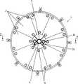
图1按照本发明的一个第一实施形式的过滤装置的简图;1 is a schematic diagram of a filter device according to a first embodiment of the present invention;
图2按图1所示沿线I-I的剖视图;Fig. 2 is by the sectional view along line I-I shown in Fig. 1;
图3按图2所示沿线II-II的剖视图;Fig. 3 is a sectional view along line II-II shown in Fig. 2;
图4按图1所示沿III-III线的通风装置的一个剖视图;Fig. 4 is a sectional view of the ventilation device along the line III-III shown in Fig. 1;
图5按箭头A(图1)方向的细节图表示出在中空轴上一个半圆形阻流板的布置情况;Fig. 5 shows the arrangement of a semicircular baffle on the hollow shaft according to the detailed diagram in the direction of arrow A (Fig. 1);
图6按照本发明的另一种实施形式的过滤装置的简图;6 is a schematic diagram of a filter device according to another embodiment of the present invention;
图7按图6中沿IV-IV线的剖视图;Fig. 7 is a sectional view along line IV-IV among Fig. 6;
图8按图7中沿V-V线的剖视图。Fig. 8 is a sectional view along line V-V in Fig. 7 .
具体实施方式Detailed ways
图1至3表示了本发明的一个第一优选的实施形式:过滤装置1可旋转地布置在一个充满液体的容器2里。它具有多个过滤模块3。各个过滤模块3组合成板状的-周边例如为圆形或多边形的过滤元件6。各个过滤元件6以一个例如为4至8mm的间隔距离而连接起来。组成过滤元件6的过滤模块3例如由多个基本上平行的过滤板(未示出)构成,正如其本身是已知的那样。通过两侧都装有过滤器的过滤板使滤出液导出。借助于间隔盘7可以调整过滤元件6之间的距离。在空腔4里水平地固定一个通风装置8。该通风装置8由平行于一个中空轴9布置的中空物体10组成,这些中空物体在存在有过滤元件6的整个宽度上延伸,而且两侧在端部处都封闭,并通过中空状的连接部分11与中空轴9的一个腔室12连通,该腔室通过管路13与一个压缩空气发生器14连通。中空物体10可以是管子,它们为了使压缩空气流出由多孔材料组成,或者设有孔15。所述与通风装置8连通的中空轴9固定支承在轴承16里。过滤元件6的范围在两侧通过支承盘17,18进行限定,该过滤元件借助于固定杆19和螺母20固定在该杆上。支承盘17,18可旋转地支承在中空轴9上的轴承21,22里。通过轴承22使过滤装置1与一个链条传动装置23相连,该链条传动装置由一个电动机24驱动(图1)。在空腔4的上半部里所述两个开孔5被阻流板25遮盖住,而该阻流板则固定在中空轴9上。这样就提高了流动对于过滤液体的作用(图1和5)。中空轴9除了有腔室12之外还有一个第二腔室26。从该腔室起通道27径向穿过中空轴9经过一个滑动环28,该滑动环与管路29连接,这些管路在通道连板30上通入并固定在支承盘17上。管路31从通道连板30分支至各个过滤模块3。中空轴9的第二腔室26通过一个管路32与一个真空泵33相连,空心物体10设有朝向下面的敞开的管接头34,以避免滤出液发生沉积。1 to 3 show a first preferred embodiment of the invention: the
作用原理如下:当过滤装置1围绕通风装置8旋转时,借助于真空泵33将滤出液从容器2里抽出,该滤出液进入过滤元件6的过滤器里并经过管路31、通道连板30、管路29、滑动环28和中空轴9的径向布置的通道27、第二个腔室26以及管路32流出。由中空物体10可以使滤出液经过管接头34漏到空腔4里,以避免固体物从滤出液里沉积下来。通过一个输入口35使过滤液体在容器2里大致保持恒定。同时通过压缩空气发生器14经过通风装置8将压缩空气吹入到空腔4里。吹入的空气向上流动。形成一种空气-液体混合物,该混合物在相邻的过滤元件之间和必要时在过滤元件内部在过滤板之间流过,并阻止固体物沉积在过滤器上。通过过滤元件6的旋转运动实现了一种顺序的清洗,因此由于过流面积小而使能耗低。此外可以据此通过向上流动的空气在开孔5处形成一个附加的抽吸,因而使过滤液体通过所述两个开孔5从容器2里抽吸出来。The principle of action is as follows: when the
图6至8表示了本发明的一个第二优选的实施形式:与第一种实施形式相反的是:围绕轴线的空腔4并不通过开孔5在轴线部位里与容器2相连通,而是在轴线部位里相对于容器2来说进行封闭。支承盘17,18为此目的一直伸到轴承21,22处,也就是沿着轴承21,22的整个圆周延伸。因此它们就形成了在容器2和空腔4之间在通风装置8的两侧的分隔板。通风装置8具有多个管段、或者说带有孔15的中空物体10。中空物体10基本垂直于中空轴9布置,并通过用于输入空气的连接部分11与该中空轴9连接。按照本发明的第一种实施形式该通风装置8原则上也可以用封闭的空腔来运行,反之亦然。Figures 6 to 8 show a second preferred embodiment of the present invention: Contrary to the first embodiment: the
由于封闭的侧板,该第二实施形式的清洗功能如下:通过通风装置8如在第一实施形式中那样产生一个在过滤板之间向上流动的空气液体混合物。后续流动的液体同样也在过滤板之间通过一个位于轴线、也就是通风装置9之下的过滤板扇段被抽吸。这种后续流动的液体则沿着旋转的过滤器的整个长度从下面起输入。这对于轴向方向上长的过滤器来说是有利的。Due to the closed side panels, the cleaning function of this second embodiment is as follows: An air-liquid mixture flowing upwards between the filter plates is generated by the
原则上也可以使空腔4和布置在其里面的吹气装置8设计得更小些。例如过滤元件6可以向中空轴9移近,而且中空轴可以只具有孔或者短的管接头作为气体出口孔。In principle, the
本发明也可以用作用于从液体中分离未溶解物的过滤装置,这种装置具有与刚才所描述的、由带有多个过滤板的模块所组成的过滤元件在结构和布置上都不同的过滤元件。The invention can also be used as a filter device for separating undissolved substances from a liquid, which has a different structure and arrangement than the filter element just described consisting of modules with a plurality of filter plates. filter element.
Claims (12)
Applications Claiming Priority (2)
| Application Number | Priority Date | Filing Date | Title |
|---|---|---|---|
| EP02406119.4 | 2002-12-19 | ||
| EP02406119.4AEP1433511B2 (en) | 2002-12-19 | 2002-12-19 | Filter device |
Publications (2)
| Publication Number | Publication Date |
|---|---|
| CN1750861A CN1750861A (en) | 2006-03-22 |
| CN100408142Ctrue CN100408142C (en) | 2008-08-06 |
Family
ID=32405825
Family Applications (1)
| Application Number | Title | Priority Date | Filing Date |
|---|---|---|---|
| CNB2003801098454AExpired - Fee RelatedCN100408142C (en) | 2002-12-19 | 2003-12-02 | filter |
Country Status (18)
| Country | Link |
|---|---|
| US (2) | US20060060521A1 (en) |
| EP (2) | EP1433511B2 (en) |
| JP (1) | JP2006510475A (en) |
| CN (1) | CN100408142C (en) |
| AT (2) | ATE358520T1 (en) |
| AU (2) | AU2003281897A1 (en) |
| CA (1) | CA2510449A1 (en) |
| CY (1) | CY1106700T1 (en) |
| DE (2) | DE50209875D1 (en) |
| ES (2) | ES2284805T3 (en) |
| HR (1) | HRP20050566B1 (en) |
| IL (1) | IL169227A (en) |
| MA (1) | MA27705A1 (en) |
| MX (1) | MXPA05006602A (en) |
| PL (1) | PL205040B1 (en) |
| RU (1) | RU2005119283A (en) |
| WO (1) | WO2004056446A1 (en) |
| ZA (1) | ZA200504946B (en) |
Families Citing this family (28)
| Publication number | Priority date | Publication date | Assignee | Title |
|---|---|---|---|---|
| US7354515B2 (en) | 2004-02-23 | 2008-04-08 | Millennium Medical Technologies, Inc. | Fluid concentrator |
| DE102004063879A1 (en)* | 2004-12-03 | 2006-06-08 | Hans Huber Ag Maschinen- Und Anlagenbau | Filtering device and method for clarifying polluted liquids |
| DE102005056586A1 (en)* | 2005-10-14 | 2007-04-19 | Hans Huber Ag Maschinen- Und Anlagenbau | filtering device |
| JP2010531142A (en)* | 2007-06-22 | 2010-09-24 | サークル バイオロジクス、 エルエルシー. | Liquid concentrator, autologous concentrated body fluid, and methods of use thereof |
| JP4959745B2 (en)* | 2009-03-31 | 2012-06-27 | 株式会社日立プラントテクノロジー | Magnetic disk drive device in magnetic separator |
| USD632801S1 (en) | 2009-05-22 | 2011-02-15 | Circle Biologics, Llc. | Fluid concentrator |
| EP2289612A1 (en)* | 2009-07-28 | 2011-03-02 | UWA Umwelt - Wasser - Abwasser GmbH & Co. KG | Rotating membrane filter device for waste water preparation |
| DE102010010709B3 (en)* | 2010-03-08 | 2011-09-08 | Tu Kaiserslautern | Apparatus and method for separating particle fractions |
| DE102010019873B4 (en) | 2010-05-07 | 2024-02-08 | A. Kayser Automotive Systems Gmbh | Filtration device |
| DE102010019871B4 (en)* | 2010-05-07 | 2018-07-12 | A. Kayser Automotive Systems Gmbh | filtration device |
| ES2372074B1 (en)* | 2010-05-27 | 2013-02-11 | Equipos Técnicos Para El Agua, S.L. | ADVANCED WATER PRE-TREATMENT UNIT. |
| DE102011002635A1 (en)* | 2011-01-13 | 2012-07-19 | Huber Se | Filtration unit for removing impurities from waste water, has shedders rotatably mounted with respect to central axis of filter modules, where each filter module has identical filter elements which are releasably connected together |
| US9011684B2 (en) | 2011-03-07 | 2015-04-21 | Spinesmith Holdings, Llc | Fluid concentrator with removable cartridge |
| CN102228756A (en)* | 2011-04-29 | 2011-11-02 | 江苏国祯环保科技有限公司 | Mud removing device for fully-submerged rotary disk filter |
| CN102274646A (en)* | 2011-08-10 | 2011-12-14 | 安徽省通源环境节能有限公司 | Novel filter plate for sludge dewatering machine |
| CN102407039B (en)* | 2011-10-31 | 2013-12-11 | 江苏松野数控科技有限公司 | Unpowered filter screen on-line cleaning system for machine tool |
| CN104069681B (en)* | 2014-07-01 | 2016-08-17 | 山西潞安环保能源开发股份有限公司常村煤矿 | A kind of rotary except suspension coal slime particl method and equipment |
| JP7044520B2 (en)* | 2017-11-16 | 2022-03-30 | 三菱化工機株式会社 | Filtration test equipment |
| DE102018101895B3 (en) | 2018-01-29 | 2019-02-07 | Akvola Technologies GmbH | Apparatus and method for generating gas bubbles in a liquid |
| CN109499186A (en)* | 2018-11-27 | 2019-03-22 | 佛山市科蓝环保科技股份有限公司 | A kind of filter screen automatic flushing device for air cleaning |
| CN111351162B (en)* | 2020-04-23 | 2025-02-07 | 于国强 | Air purification device |
| DE102020133470B4 (en)* | 2020-12-15 | 2023-12-21 | Mack Gmbh | Cleaning device and method for cleaning a filter arrangement |
| CN114073868B (en)* | 2021-11-30 | 2023-07-04 | 宁波大地化工环保有限公司 | Self-circulation filtering system and filtering process thereof |
| CN114797196B (en)* | 2022-05-18 | 2023-11-28 | 中国农业科学院农田灌溉研究所 | An automatic sewage suction micro-irrigation sand and gravel filter |
| CN118371047A (en)* | 2023-04-06 | 2024-07-23 | 王超群 | A ceramic pigment water-soluble substance filtering device |
| CN116139580B (en)* | 2023-04-23 | 2023-07-04 | 深圳市微加电子科技有限公司 | Resin filter convenient for discharging |
| CN117285099B (en)* | 2023-11-27 | 2024-02-09 | 深圳市深水水务咨询有限公司 | Garden biological irrigation water purifying equipment |
| CN119034321B (en)* | 2024-10-30 | 2025-08-22 | 金锋馥(滁州)科技股份有限公司 | An organic planting solution recovery and processing system |
Citations (5)
| Publication number | Priority date | Publication date | Assignee | Title |
|---|---|---|---|---|
| CN2203895Y (en)* | 1994-08-08 | 1995-07-26 | 满金声 | Multi-stage parallel rotating discs filter |
| US5482625A (en)* | 1994-01-07 | 1996-01-09 | Kubota Corporation | Filtration membrane module |
| CN2363773Y (en)* | 1999-02-05 | 2000-02-16 | 陈国金 | Leaf filter capable of automatically discharging filter residue |
| FR2799391A1 (en)* | 1999-10-07 | 2001-04-13 | Degremont | Biological filter station for treatment of waste water and sewage has membranes supported by angled disks on rotating horizontal shaft with rising gas bubble stream to scour the membranes |
| EP1149619A1 (en)* | 2000-04-20 | 2001-10-31 | Martin Systems AG | Filter device for clarifying contaminated liquids |
Family Cites Families (5)
| Publication number | Priority date | Publication date | Assignee | Title |
|---|---|---|---|---|
| US3997447A (en)* | 1974-06-07 | 1976-12-14 | Composite Sciences, Inc. | Fluid processing apparatus |
| JPS61274799A (en)* | 1985-05-31 | 1986-12-04 | Agency Of Ind Science & Technol | Apparatus for treating waste water |
| DK0510328T3 (en)* | 1991-03-07 | 1996-02-05 | Kubota Kk | Apparatus for treating activated sludge |
| RU2033843C1 (en)* | 1992-06-19 | 1995-04-30 | Анатолий Васильевич Соколов | Filter for suspension separation |
| GB9914854D0 (en)* | 1999-06-25 | 1999-08-25 | Wilkes Ian P | Self cleaning membrane device for filtration used in submerged operation |
- 2002
- 2002-12-19ATAT02406119Tpatent/ATE358520T1/ennot_activeIP Right Cessation
- 2002-12-19DEDE50209875Tpatent/DE50209875D1/ennot_activeExpired - Lifetime
- 2002-12-19ESES02406119Tpatent/ES2284805T3/ennot_activeExpired - Lifetime
- 2002-12-19EPEP02406119.4Apatent/EP1433511B2/ennot_activeExpired - Lifetime
- 2003
- 2003-12-02AUAU2003281897Apatent/AU2003281897A1/ennot_activeAbandoned
- 2003-12-02HRHR20050566Apatent/HRP20050566B1/ennot_activeIP Right Cessation
- 2003-12-02DEDE50305799Tpatent/DE50305799D1/ennot_activeExpired - Lifetime
- 2003-12-02MXMXPA05006602Apatent/MXPA05006602A/enactiveIP Right Grant
- 2003-12-02JPJP2004560975Apatent/JP2006510475A/ennot_activeWithdrawn
- 2003-12-02USUS10/539,139patent/US20060060521A1/ennot_activeAbandoned
- 2003-12-02RURU2005119283/15Apatent/RU2005119283A/ennot_activeApplication Discontinuation
- 2003-12-02ESES03773412Tpatent/ES2277124T3/ennot_activeExpired - Lifetime
- 2003-12-02PLPL375932Apatent/PL205040B1/ennot_activeIP Right Cessation
- 2003-12-02CACA002510449Apatent/CA2510449A1/ennot_activeAbandoned
- 2003-12-02EPEP03773412Apatent/EP1583597B9/ennot_activeExpired - Lifetime
- 2003-12-02CNCNB2003801098454Apatent/CN100408142C/ennot_activeExpired - Fee Related
- 2003-12-02ATAT03773412Tpatent/ATE345861T1/enactive
- 2003-12-02WOPCT/CH2003/000793patent/WO2004056446A1/enactiveIP Right Grant
- 2005
- 2005-06-16ILIL169227Apatent/IL169227A/ennot_activeIP Right Cessation
- 2005-06-17ZAZA200504946Apatent/ZA200504946B/enunknown
- 2005-07-11MAMA28379Apatent/MA27705A1/enunknown
- 2007
- 2007-07-03CYCY20071100886Tpatent/CY1106700T1/enunknown
- 2010
- 2010-09-09AUAU2010219360Apatent/AU2010219360B2/ennot_activeExpired - Fee Related
- 2012
- 2012-06-01USUS13/486,248patent/US20120234747A1/ennot_activeAbandoned
Patent Citations (5)
| Publication number | Priority date | Publication date | Assignee | Title |
|---|---|---|---|---|
| US5482625A (en)* | 1994-01-07 | 1996-01-09 | Kubota Corporation | Filtration membrane module |
| CN2203895Y (en)* | 1994-08-08 | 1995-07-26 | 满金声 | Multi-stage parallel rotating discs filter |
| CN2363773Y (en)* | 1999-02-05 | 2000-02-16 | 陈国金 | Leaf filter capable of automatically discharging filter residue |
| FR2799391A1 (en)* | 1999-10-07 | 2001-04-13 | Degremont | Biological filter station for treatment of waste water and sewage has membranes supported by angled disks on rotating horizontal shaft with rising gas bubble stream to scour the membranes |
| EP1149619A1 (en)* | 2000-04-20 | 2001-10-31 | Martin Systems AG | Filter device for clarifying contaminated liquids |
Also Published As
| Publication number | Publication date |
|---|---|
| AU2010219360B2 (en) | 2011-07-07 |
| ES2284805T3 (en) | 2007-11-16 |
| AU2003281897A2 (en) | 2004-07-14 |
| CY1106700T1 (en) | 2012-05-23 |
| EP1433511B1 (en) | 2007-04-04 |
| CN1750861A (en) | 2006-03-22 |
| EP1583597A1 (en) | 2005-10-12 |
| EP1583597B9 (en) | 2008-03-19 |
| MA27705A1 (en) | 2006-01-02 |
| PL375932A1 (en) | 2005-12-12 |
| HRP20050566A2 (en) | 2005-12-31 |
| CA2510449A1 (en) | 2004-07-08 |
| ZA200504946B (en) | 2006-08-30 |
| AU2003281897A1 (en) | 2004-07-14 |
| EP1583597B1 (en) | 2006-11-22 |
| RU2005119283A (en) | 2006-01-27 |
| US20120234747A1 (en) | 2012-09-20 |
| EP1433511A1 (en) | 2004-06-30 |
| AU2010219360A1 (en) | 2010-09-30 |
| DE50305799D1 (en) | 2007-01-04 |
| ATE358520T1 (en) | 2007-04-15 |
| US20060060521A1 (en) | 2006-03-23 |
| WO2004056446A1 (en) | 2004-07-08 |
| JP2006510475A (en) | 2006-03-30 |
| MXPA05006602A (en) | 2006-02-22 |
| EP1433511B2 (en) | 2014-03-05 |
| ATE345861T1 (en) | 2006-12-15 |
| ES2277124T3 (en) | 2007-07-01 |
| HRP20050566B1 (en) | 2008-06-30 |
| IL169227A (en) | 2009-05-04 |
| DE50209875D1 (en) | 2007-05-16 |
| PL205040B1 (en) | 2010-03-31 |
Similar Documents
| Publication | Publication Date | Title |
|---|---|---|
| CN100408142C (en) | filter | |
| FI113637B (en) | Clearer | |
| FI94840B (en) | Liquid filtration device | |
| FI94839C (en) | Device for filtration of sludge and method of use of the devices | |
| FI90500C (en) | Water clarification equipment for the removal of fines larger than a predetermined size | |
| US20060144768A1 (en) | Filtrate immersed activation assembly for disk filters | |
| US10653982B2 (en) | Vacuum box, belt filter, methods for servicing a vacuum belt filter, method for liquid-solid separation of a slurry, and filter element | |
| EP3758825B1 (en) | Filtering apparatus and method | |
| JP2003530998A (en) | Filter device for purifying contaminated liquid | |
| JP2002126800A (en) | Rotary disk type filtration device | |
| KR200388784Y1 (en) | upward flow type multi-stage filter apparatus | |
| KR100758875B1 (en) | Rotary Upflow Water Filtration Device | |
| JP3909980B2 (en) | Suspension concentration granulator | |
| CN101072616A (en) | Filtration device and method for purifying contaminated liquid | |
| KR100646309B1 (en) | Rotary multilayer membrane upflow water filtration | |
| JPH038404A (en) | Liquid cleaning device provided with centrifugal self-cleaning filter | |
| JP2003320372A (en) | Filter for water environment | |
| JP2002166111A (en) | Solid-liquid separation device |
Legal Events
| Date | Code | Title | Description |
|---|---|---|---|
| C06 | Publication | ||
| PB01 | Publication | ||
| C10 | Entry into substantive examination | ||
| SE01 | Entry into force of request for substantive examination | ||
| C14 | Grant of patent or utility model | ||
| GR01 | Patent grant | ||
| C17 | Cessation of patent right | ||
| CF01 | Termination of patent right due to non-payment of annual fee | Granted publication date:20080806 Termination date:20131202 |