CN100406176C - Planers and planers - Google Patents
Planers and planersDownload PDFInfo
- Publication number
- CN100406176C CN100406176CCNB2005100531270ACN200510053127ACN100406176CCN 100406176 CCN100406176 CCN 100406176CCN B2005100531270 ACNB2005100531270 ACN B2005100531270ACN 200510053127 ACN200510053127 ACN 200510053127ACN 100406176 CCN100406176 CCN 100406176C
- Authority
- CN
- China
- Prior art keywords
- planer
- frame
- cutting cylinder
- cover
- cutting
- Prior art date
- Legal status (The legal status is an assumption and is not a legal conclusion. Google has not performed a legal analysis and makes no representation as to the accuracy of the status listed.)
- Expired - Fee Related
Links
Images


Classifications
- B—PERFORMING OPERATIONS; TRANSPORTING
- B27—WORKING OR PRESERVING WOOD OR SIMILAR MATERIAL; NAILING OR STAPLING MACHINES IN GENERAL
- B27G—ACCESSORY MACHINES OR APPARATUS FOR WORKING WOOD OR SIMILAR MATERIALS; TOOLS FOR WORKING WOOD OR SIMILAR MATERIALS; SAFETY DEVICES FOR WOOD WORKING MACHINES OR TOOLS
- B27G21/00—Safety guards or devices specially designed for other wood-working machines auxiliary devices facilitating proper operation of said wood-working machines
- B—PERFORMING OPERATIONS; TRANSPORTING
- B27—WORKING OR PRESERVING WOOD OR SIMILAR MATERIAL; NAILING OR STAPLING MACHINES IN GENERAL
- B27C—PLANING, DRILLING, MILLING, TURNING OR UNIVERSAL MACHINES FOR WOOD OR SIMILAR MATERIAL
- B27C1/00—Machines for producing flat surfaces, e.g. by rotary cutters; Equipment therefor
- B27C1/06—Machines for smoothing and subsequent thicknessing
- B—PERFORMING OPERATIONS; TRANSPORTING
- B27—WORKING OR PRESERVING WOOD OR SIMILAR MATERIAL; NAILING OR STAPLING MACHINES IN GENERAL
- B27C—PLANING, DRILLING, MILLING, TURNING OR UNIVERSAL MACHINES FOR WOOD OR SIMILAR MATERIAL
- B27C1/00—Machines for producing flat surfaces, e.g. by rotary cutters; Equipment therefor
- B27C1/12—Arrangements for feeding work
- B—PERFORMING OPERATIONS; TRANSPORTING
- B27—WORKING OR PRESERVING WOOD OR SIMILAR MATERIAL; NAILING OR STAPLING MACHINES IN GENERAL
- B27C—PLANING, DRILLING, MILLING, TURNING OR UNIVERSAL MACHINES FOR WOOD OR SIMILAR MATERIAL
- B27C1/00—Machines for producing flat surfaces, e.g. by rotary cutters; Equipment therefor
- B27C1/14—Other details or accessories
Landscapes
- Life Sciences & Earth Sciences (AREA)
- Engineering & Computer Science (AREA)
- Mechanical Engineering (AREA)
- Wood Science & Technology (AREA)
- Forests & Forestry (AREA)
- Milling, Drilling, And Turning Of Wood (AREA)
- Crushing And Grinding (AREA)
- Fuel Cell (AREA)
- Diaphragms For Electromechanical Transducers (AREA)
- Golf Clubs (AREA)
- Electrical Discharge Machining, Electrochemical Machining, And Combined Machining (AREA)
- Slot Machines And Peripheral Devices (AREA)
- Sawing (AREA)
Abstract
Description
Translated fromChinese技术领域technical field
本发明涉及一种刨床和刨板机。The invention relates to a planer and planer.
背景技术Background technique
典型的刨床和刨板机包括一个包括有水平矩形上操作台和一个底部的箱状框架,上操作台和底部沿其较长的一侧由两个侧壁彼此连接在一起。该水平上操作台位于所述矩形底部的正上方。一个第一孔由上操作台的较短端之一和所述底部以及所述两个侧壁中每个侧壁的一端形成。类似地,在所述矩形箱式框架的相对侧上,由上操作台的另一较短端和所述底部的另一端,以及所述侧壁中每一侧壁的另一端形成一个第二孔。通过一个通道将所述两个孔连接起来。Typical planers and planers consist of a box-like frame including a horizontal rectangular upper table and a bottom joined to each other along their longer sides by two side walls. The horizontal upper operating platform is located directly above the rectangular bottom. A first aperture is formed by one of the shorter ends of the upper console and the bottom and an end of each of the two side walls. Similarly, on the opposite side of the rectangular box frame, a second short end is formed by the other shorter end of the upper platform and the other end of the bottom, and the other end of each of the side walls. hole. The two holes are connected by a channel.
所述上操作台由两个矩形区域构成,即一个前部区域和一个后部区域。所述上操作台的两个区域由具有光滑顶面的单一矩形金属片构成。前部区域的顶面平行于后部区域的顶面。所述两个顶面都是光滑的,以使工件可在其表面上滑过。可相对于后部区域的高度来调节前部区域的高度。所述两个区域由一个槽分隔开。The upper console consists of two rectangular areas, namely a front area and a rear area. The two regions of the upper console consist of a single rectangular sheet of metal with a smooth top surface. The top surface of the front region is parallel to the top surface of the rear region. Both top surfaces are smooth so that the workpiece can slide over them. The height of the front area can be adjusted relative to the height of the rear area. The two areas are separated by a groove.
一个水平的下操作台安置在所述通道内且是可移动的。该下操作台的平面平行于该上操作台的平面。该下操作台被构造成具有一个光滑顶面的单一矩形金属片。下操作台从第一孔延伸到第二孔贯穿通道的整个长度。所述台的宽度略小于所述通道宽度。所述台的安装方式是使其可向上或向下垂直移动,并且在此过程中,所述台的顶面一直保持水平。A horizontal lower platform is housed in the tunnel and is movable. The plane of the lower operating platform is parallel to the plane of the upper operating platform. The lower console is constructed as a single rectangular sheet of metal with a smooth top surface. The lower deck extends from the first aperture to the second aperture throughout the entire length of the channel. The width of the table is slightly smaller than the channel width. The table is mounted in such a way that it can be moved vertically up or down, and during this process, the top surface of the table remains horizontal.
一个切削圆筒可旋转地安装在所述两个侧壁之间,使其旋转轴垂直于侧壁的平面且平行于上操作台和下操作台的平面。所述切削圆筒可由一个安装在所述底部内的电动机旋转驱动。所述切削圆筒的旋转轴位于上操作台的下方。A cutting cylinder is rotatably mounted between the two side walls such that its axis of rotation is perpendicular to the plane of the side walls and parallel to the planes of the upper and lower operating tables. The cutting cylinder is rotatably driven by an electric motor mounted in the base. The rotation axis of the cutting cylinder is located below the upper operating table.
所述切削圆筒外围的一部分沿其长度方向向上延伸,穿过在上操作台的前部区域和后部区域之间的槽。A portion of the periphery of the cutting cylinder extends upwardly along its length through the slot between the front and rear regions of the upper table.
两个切削刀片中每个刀片都安装在切削圆筒(cutting drum)的一个凹槽内,所述凹槽平行于旋转轴,以众所周知的方式沿切削圆筒的长度方向延伸。切削圆筒的切削刀片可用于以众所周知的方式切割工件,所述工件沿一个方向滑过上操作台或沿另一个方向滑过下操作台。Each of the two cutting inserts is mounted in a groove in a cutting drum, parallel to the axis of rotation, extending in a known manner along the length of the cutting drum. The cutting blades of the cutting cylinder can be used in well known manner to cut workpieces which slide in one direction over the upper table or in the other direction over the lower table.
所述切削圆筒的位置被设成使得在切削圆筒旋转时,安装在穿过所述槽的切削圆筒内部的切削刀片的最大高度与上操作台的后部区域的高度大致相同,相对于框架固定所述后部区域的高度。The cutting cylinder is positioned such that when the cutting cylinder rotates, the maximum height of the cutting blades mounted inside the cutting cylinder passing through the slots is approximately the same as the height of the rear area of the upper console, as opposed to Fix the height of the rear area to the frame.
将两个驱动滚筒安装在所述侧壁之间的切削圆筒的任一侧面上,使其旋转轴平行于切削圆筒的旋转轴。所述两个驱动滚筒由用于驱动所述切削圆筒的相同电动机旋转驱动。所述两个驱动滚筒的功能是迫使任何送入所述矩形通道中的工件滑过下操作台并随着旋转切削圆筒转动而在最低点与切削刀片接合。Two drive rollers are mounted on either side of the cutting cylinder between said side walls with their axes of rotation parallel to the axis of rotation of the cutting cylinder. The two drive drums are driven in rotation by the same electric motor used to drive the cutting drum. The function of the two drive rollers is to force any workpiece fed into the rectangular channel to slide over the lower table and engage the cutting blades at their lowest point as the rotating cutting drum turns.
刨床和刨板机可用于两种不同的操作模式。Planers and planers can be used in two different modes of operation.
在第一操作模式下,使工件滑过上操作台,以去除邻近上操作台的光滑顶面的工件表面。上操作台的前部区域的高度决定了将从所述工件上去除的材料的量。首先,调节前部区域的高度,使旋转圆筒的切削动作可从工件的下表面上去除恰当厚度的材料。其次,接着使切削圆筒由电动机旋转驱动。然后,在切削圆筒旋转的同时,使工件滑过上操作台的前部区域,直到所述工件与转动的切削圆筒的切削刀片接合,所述切削刀片重复地通过前部区域和后部区域之间的槽。而后,推动工件通过旋转的切削圆筒而到达上操作台的后部区域上。当所述工件经过切削圆筒的旋转刀片上方时,所述切削刀片将去除工件下侧的材料。In a first mode of operation, the workpiece is slid over the upper table to remove the surface of the workpiece adjacent the smooth top surface of the upper table. The height of the front area of the upper table determines the amount of material to be removed from the workpiece. First, the height of the front section is adjusted so that the cutting action of the rotating cylinder removes the correct thickness of material from the lower surface of the workpiece. Second, the cutting cylinder is then driven in rotation by the electric motor. The workpiece is then slid across the front area of the upper table while the cutting cylinder is rotating until it engages the cutting blades of the rotating cutting cylinder, which repeatedly pass through the front area and the rear Slots between regions. The workpiece is then pushed through the rotating cutting cylinder onto the rear area of the upper table. As the workpiece passes over the rotating blades of the cutting cylinder, the cutting blades remove material from the underside of the workpiece.
在第二操作模式下,使工件滑过下操作台的光滑表面,以去除所述工件的顶面。通道中下操作台的高度决定了当所述工件穿过通道时将从其顶面上去除的材料的量。首先,调节下操作台的高度,使旋转圆筒的切削动作可从工件的顶面上去除恰当厚度的材料。其次,接着使切削圆筒由电动机旋转驱动。在切削圆筒旋转的同时,使工件滑过下操作台,直到所述工件的上表面与转动中的切削圆筒的旋转切削刀片接合。当工件通过切削刀片下方时,切削刀片从所述工件的顶面去除材料。所述两个同样由电动机旋转驱动的驱动滚筒迫使工件穿过通道。In the second mode of operation, the workpiece is slid across the smooth surface of the lower table to remove the top surface of the workpiece. The height of the lower table in the tunnel determines the amount of material that will be removed from the top surface of the workpiece as it passes through the tunnel. First, the height of the lower table is adjusted so that the cutting action of the rotating cylinder removes the correct thickness of material from the top surface of the workpiece. Second, the cutting cylinder is then driven in rotation by the electric motor. While the cutting cylinder is rotating, the workpiece is slid over the lower table until the upper surface of the workpiece engages the rotating cutting blades of the rotating cutting cylinder. The cutting blade removes material from the top surface of the workpiece as the workpiece passes beneath the cutting blade. The two drive rollers, also rotationally driven by the electric motor, force the workpiece through the channel.
然而,存在大量与刨床和刨板机的现有设计相关的问题。However, there are a number of problems associated with existing designs of planers and planers.
发明内容Contents of the invention
本发明的目的在于改进刨床和刨板机的设计和构造。The object of the present invention is to improve the design and construction of planers and planers.
根据本发明的第一方面,提供一种刨床和刨板机,其包括:一个具有一个通道的框架,所述通道从所述框架的一壁上的一个孔延伸到其一壁上的另一个孔而贯穿所述框架;According to a first aspect of the present invention there is provided a planer and board machine comprising: a frame having a channel extending from an aperture in one wall of the frame to another in one wall thereof holes extending through the frame;
一个具有一前部区域和一后部区域的上操作台,其前部区域和后部区域被安装在所述框架上,以便在所述上操作台的前部区域与后部区域之间形成一个槽;an upper console having a front region and a rear region, the front region and the rear region being mounted on the frame so as to form between the front region and the rear region of the upper console a slot;
一个切削圆筒,其被可旋转地安装在所述框架内,使所述切削圆筒外围的上部纵向区域向上突出穿过所述槽,且其外围的下部纵向区域向下突出到所述通道中;a cutting cylinder rotatably mounted within the frame such that an upper longitudinal region of the periphery of the cutting cylinder projects upwardly through the slot and a lower longitudinal region of the periphery projects downwardly into the channel middle;
一个下操作台,其大体上平行于所述上操作台,安装在所述通道内部或形成所述通道的底部,且位于切削圆筒下方;a lower table, substantially parallel to said upper table, mounted inside or forming the bottom of said channel and located below the cutting cylinder;
一个安装于所述上操作台上方的盖,其能够从一第一位置移动到一第二位置,其中,在所述第一位置处,其邻近所述上操作台并覆盖向上突出穿过所述槽的所述切削圆筒的外围的纵向区域;在所述第二位置处,其位于所述上操作台上方并离开所述上操作台,a cover mounted over the upper console movable from a first position to a second position, wherein in the first position it is adjacent to the upper console and covers projecting upwardly through the the longitudinal region of the periphery of the cutting cylinder of the groove; in the second position, it is located above and away from the upper table,
所述盖的特征在于:其可相对于上操作台的平面从所述第一位置垂直移动到所述第二位置并以一套筒式框架安装到所述框架上。The cover is characterized in that it is vertically movable relative to the plane of the upper console from the first position to the second position and is mounted to the frame by a telescopic frame.
附图说明Description of drawings
现将参考附图描述上述本发明的各个实施例。Various embodiments of the present invention described above will now be described with reference to the accompanying drawings.
图1显示一个刨床和刨板机的轮廓的概略斜视图;Figure 1 shows a schematic oblique view of the outline of a planer and planer;
图2显示用于所述槽的盖子的透视图,其中当切削圆筒旋转时,旋转的切削圆筒的外围和切削刀片穿过所述槽突出于上操作台上;Figure 2 shows a perspective view of the cover for the slot, wherein the periphery of the rotating cutting drum and the cutting blades protrude through the slot onto the upper table as the cutting drum rotates;
图3显示图2的盖子的高度调节机构;Fig. 3 shows the height adjustment mechanism of the lid of Fig. 2;
图4显示下操作台的延长部;Figure 4 shows the extension of the lower console;
图5显示侧导板组件;Figure 5 shows the side guide assembly;
图6显示当护板处于第一倾斜角时,侧导板组件的倾斜机构的侧视图;Figure 6 shows a side view of the tilt mechanism of the side guide assembly when the guard is at a first tilt angle;
图7显示当护板处于第二倾斜角时,侧导板组件的倾斜机构的侧视图;Figure 7 shows a side view of the tilt mechanism of the side guide assembly when the guard is at a second tilt angle;
图8和图9显示侧导板组件的滑动机构的侧视图;Figures 8 and 9 show side views of the slide mechanism of the side guide assembly;
图10显示一个滑动导向件;Figure 10 shows a sliding guide;
图11显示用于控制上操作台的前部区域的运动的驱动机构;Figure 11 shows the drive mechanism for controlling the movement of the front area of the upper console;
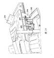
图12显示用于两个滚筒和切削圆筒的驱动机构;Figure 12 shows the drive mechanism for the two drums and the cutting cylinder;
图13显示所述两个滚筒;Figure 13 shows the two rollers;
图14和图15显示下操作台的高度调节机构;Figure 14 and Figure 15 show the height adjustment mechanism of the lower operating platform;
图16和图17显示上操作台的后部区域的安装机构;Figures 16 and 17 show the mounting mechanism for the rear area of the upper console;
图18显示集尘器的俯视透视图;Figure 18 shows a top perspective view of the dust collector;
图19和图20分别显示处于上操作台的上方和下方的集尘器;Figure 19 and Figure 20 show the dust collector above and below the upper operating platform, respectively;
图21显示所述刨床和刨板机的后视图;Figure 21 shows a rear view of the planer and planer;
图22显示所述刨床和刨板机的向下观看所得的正视图;Figure 22 shows a front view looking down on the planer and planer;
图23显示所述刨床和刨板机的正视图;Figure 23 shows a front view of the planer and planer;
图24显示所述刨床和刨板机的侧视图;和Figure 24 shows a side view of the planer and planer; and
图25显示所述刨床和刨板机的从另一侧观察所得的视图。Figure 25 shows a view of the planer and planer from the other side.
具体实施方式Detailed ways
本实施例的刨床和刨板机包括一个矩形箱状框架2,框架2包括一个水平矩形上操作台4和一个矩形底部6,该两部分沿其较长的相应一侧由两个垂直侧壁8、10相互连接在一起。水平上操作台4位于矩形底部6的正上方并平行于其延伸。第一矩形孔12由上操作台4的较短端之一和底部的较短端之一以及两个侧壁8、10中每一侧壁的一端形成。相似地,在矩形箱式框架2的相对侧上由上操作台4和矩形底部6的另两个较短端和所述侧壁中每一侧壁的另一端形成第二矩形孔。一个横截面呈矩形的通道22将所述两个矩形孔12彼此连接在一起,该两个矩形孔12大体上彼此平行。The planer and planer of the present embodiment comprises a rectangular box-like frame 2 comprising a horizontal rectangular upper table 4 and a
上操作台4由两个矩形区域构成,即前部区域14和后部区域16。上操作台的所述两个区域14、16是由具有光滑顶面的单一矩形金属片构成。前部区域的顶面平行于后部区域的顶面。两个顶面都是光滑的,以使工件可于其表面上滑过。前部区域14的高度可相对于后部区域16的高度来调节。用来调节高度的机构将在下文中进行更详细的描述。所述两个区域14、16由窄槽18分隔开。The upper console 4 is composed of two rectangular areas, a
水平下操作台20可移动地位于矩形通道22内。下操作台的表面平行于上操作台的表面。下操作台20被制作成具有光滑顶面的单一矩形金属片。下操作台20贯穿通道22的整个长度并从第一孔12延伸到第二孔。台20的宽度略小于通道22的宽度。台20的安装是为使其能够如图1中箭头A所示向上或向下垂直移动。在台20的移动过程中,台20的顶面始终保持水平。用于使下操作台20上下移动的机构将在下文中予以更详细的描述。The horizontal
切削圆筒24可旋转地安装于所述两个侧壁8、10之间。切削圆筒24的安装方式为使其旋转轴垂直于侧壁8、10的平面且平行于上操作台和下操作台4、20的平面。切削圆筒24可由一个安装于矩形箱式框架2的底部6的电动机(未图示)旋转驱动。切削圆筒24由电动机旋转驱动所使用的机构将在下文中予以更详细的描述。A cutting cylinder 24 is rotatably mounted between said two
切削圆筒24外围的一部分26沿其长度方向延伸穿过上操作台4的前部区域和后部区域14、16之间的槽。A
两个切削刀片28安装于切削圆筒24的凹槽内。该凹槽平行于旋转轴以众所周知的方式沿切削圆筒24的长度方向延伸。切削圆筒的所述切削刀片28可用于以众所周知的方式切割工件。例如,工件可沿一个方向滑过上操作台4或沿另一个方向滑过下操作台20。Two cutting
切削圆筒24的定位为:当切削圆筒24旋转时,安装于穿过所述槽18的切削圆筒24内部的切削刀片28的最大高度与上操作台的后部区域16的高度相同,所述后部区域16的高度固定。The cutting cylinder 24 is positioned such that when the cutting cylinder 24 rotates, the maximum height of the
两个驱动滚筒30、32安装于所述侧壁之间的切削圆筒的任一侧面上,其安装方式为使其旋转轴平行于切削圆筒24的旋转轴。该两个驱动滚筒30、32由用于驱动切削圆筒24的同一电动机旋转驱动。电动机旋转驱动两个驱动滚筒30、32的机构将在下文中予以更详细的描述。该两个驱动滚筒30、32的功能是迫使任何送入矩形通道22中的工件滑过下操作台20并当所述工件通过旋转切削圆筒24的旋转轴下方时,在切削圆筒24的最低点处与切削刀片28接合。Two drive rollers 30 , 32 are mounted on either side of the cutting cylinder between said side walls in such a way that their axes of rotation are parallel to the axis of rotation of the cutting cylinder 24 . The two drive drums 30 , 32 are driven in rotation by the same electric motor that drives the cutting drum 24 . The mechanism by which the motor rotates the two drive rollers 30, 32 will be described in more detail below. The function of the two drive rollers 30, 32 is to force any work piece fed into the
所述刨床和刨板机可用于两种不同的操作模式。The planer and planer can be used in two different modes of operation.
在第一操作模式下,将工件滑过上操作台4,以去除邻近上操作台4的光滑顶面的工件表面。上操作台4的前部区域14的高度决定了将从工件上去除的材料的量。调节前部区域14的高度,使旋转圆筒24的切削动作从工件的下表面上去除恰当厚度的材料。接着,切削圆筒24由电动机旋转驱动。在切削圆筒24旋转的同时,将工件滑过上操作台的前部区域14,直到该工件与转动的切削圆筒24的切削刀片28接合,切削刀片28重复地通过前部区域14和后部区域16之间的槽18。而后,将工件通过旋转的切削圆筒24滑动到上操作台的后部区域16上。当工件经过切削圆筒24的旋转刀片28上方时,切削刀片28将工件下侧的材料去除。In the first mode of operation, the workpiece is slid over the upper table 4 to remove the surface of the workpiece adjacent to the smooth top surface of the upper table 4 . The height of the
在第二操作模式时,将工件滑过下操作台20的光滑表面,以去除工件的顶面。在通道22内下操作台20的高度决定了当工件穿过通道22时将从其顶面上去除的材料的量。将下操作台的高度调节,使旋转圆筒24的切削动作可从工件的顶面上去除恰当厚度的材料。接着,将切削圆筒24由电动机旋转驱动。在切削圆筒24旋转的同时,将工件滑过下操作台20,直至工件的上表面与转动中的切削圆筒24的旋转切削刀片28接合。当工件通过切削刀片28下方时,切削刀片28从工件的顶面去除材料。同样由电动机旋转驱动的两个驱动滚筒30、32迫使工件穿过通道22。In the second mode of operation, the workpiece is slid across the smooth surface of the lower table 20 to remove the top surface of the workpiece. The height of the lower table 20 within the
当刨床和刨板机用于第二操作模式时,最好能将一个盖子放置在上操作台中的槽28上方,以覆盖突出于槽28的旋转切削圆筒24的外围和切削刀片28部分。现将参考图2和图3来描述根据本发明当前实施例的盖子的构造。When the planer and planer are used in the second mode of operation, it is desirable to place a cover over the
盖子包括一个位于刨床和刨板机上操作台4上方的沿宽度方向延伸的弧形矩形护罩34。弧形护罩34的长度略大于上操作台4的两个区域14、16的宽度。弧形护罩34具有足够宽度,使其可完全覆盖上操作台4的前部区域与后部区域14、16之间的槽18,弧形护罩34的较长边缘36亦可分别与上操作台的前部与后部区域14、16接合。护罩34呈弧形,以使当其被搁置在上操作台4上,及在弧形护罩的纵向边缘36与上操作台的前部区域和后部区域14、16接合时,其可包围圆形的切削圆筒24的部分26,或可包围从前部区域与后部区域14、16之间的槽18突出穿过的切削刀片28,同时却不会接触到切削刀片28或切削圆筒24,以允许当护罩34置于槽上方时,切削刀片28或切削圆筒24可自由旋转。The cover includes a curved
弧形护罩34被可滑动地支撑在支架38下方。弧形护罩34能够在支架38内沿着平行于切削圆筒24的旋转轴和槽18的纵轴的方向(即沿上操作台4的宽度方向)滑动。这使得当刨床和刨板机用于第一操作模式时,弧形护罩34可滑离槽18,从而可使用上操作台4。一个挡止件40位于弧形护罩34的一端,以防止弧形护罩滑动距离过远而穿过支架38。一个螺栓(未图示)与所述支架螺纹接合,以使螺栓的旋转可使其垂直地旋入或旋出支架38。当螺栓被旋入支架38时,螺栓的下端与弧形护罩34的上表面接合,从而将弧形护罩34锁定在相对于支架38的恰当位置上,以防止其在支架内滑动。一个旋钮42连接到螺栓相反的上端处,以允许使用者将螺栓旋入或旋出支架38。
支架38通过一个套筒式框架连接到刨床和刨板机的侧壁10。所述框架使使用者可以调节支架38的高度,并因此可调节上操作台4上方的弧形护罩34。所述框架包括两个区域:一个下部框架区域44,其包括一个横截面呈正方形的下部金属管,所述下部金属管安装于刨床和刨板机的侧壁10上,其纵向轴是大体上垂直的;和一个上部框架区域46,其包括一个横截面呈类似正方形的上部金属管;和一个水平金属杆48。上部金属管46具有较小的横截面面积,以使其能够滑入或滑出所述下部金属管44。在下部框架区域44的一侧上形成一个孔(未图示),所述孔刻有螺纹以允许将螺栓50旋入或旋出下部金属管44。把手52连接到螺栓50的一端。螺栓50用于固定上部金属管46在下部金属管44中的位置,即,通过使下部金属管44中螺栓50的端部与上部金属管46的侧面接合而实现该固定。The
从上部框架区域的上部金属管46侧向延伸的金属杆48将支架38连接到上部金属管46。
在使用过程中,通过使用把手50旋开螺栓50,使螺栓的端部与上部金属管46的侧面脱离接触;使上部金属管滑入或滑出下部金属管44;并接着将螺栓50旋入下部金属管44中,使其端部与上部金属管46的侧面接合,因而将上部金属管46锁定在预设位置,由此将其与支架38锁定在预定高度,使得操作者能够降低或提升支架38,进而降低或提升弧形护罩34。In use, by unscrewing the
在下部金属管的另一个壁上形成一个垂直的细长的槽54。将另一个螺栓56旋入上部金属管46的侧面中,其螺栓头穿过槽54。槽54和螺栓56的功能是限制上部金属管46在下部金属管44中垂直移动的范围并且也防止其被从下部金属管44中移走。A vertical
通过调节支架38的高度并通过弧形护罩34在支架38中的滑动运动,操作者能够将弧形护罩34移动到一位置中,在此处其覆盖向上突出穿过槽18的旋转切削圆筒24的部分26和刀片28,并能够将其移动到另一位置处,在此处其离开向上突出穿过槽18的切削圆筒24的部分26和切削刀片28,以允许上操作台4可自由用于刨床和刨板机的第一操作模式中。By adjusting the height of the
现将参看图4描述本发明的当前实施例的下操作台20的一个延长部的构造。The configuration of an extension of the
所述延长部包括两个相同形状的延长杆58、60,所述两个延长杆58、60都附接到下操作台20的端部62上并在下操作台20所在平面中彼此平行地沿水平方向延伸,从下操作台20向外延伸穿过所述孔12中的一个孔并延伸出矩形箱式框架2。两个延长杆64、66连接于所述两个延长杆58、60之间。所述两个延长杆64、66相互平行地加以固定,其中的一个杆64连接于延长杆58、60的两端之间,另一个杆66连接于两个杆58、60之间并位于沿两个杆长度方向的半途处。The extension comprises two identically shaped
刨床和刨板机的上操作台4的前部区域14和后部区域16都稳固地附接到矩形箱式框架2上(尽管可调节前部区域14相对于矩形箱式框架的高度)。因而,操作者接近下操作台20变得十分困难。这导致操作者难以在使工件穿过通道22之前将其送入孔12中。通过提供下操作台20的延长部,可使操作者能够在刨床和刨板机用于第二操作模式下时较轻松地将工件送入刨床和刨板机中。Both the
现将参考图5到图9来描述根据本发明当前实施例的侧导板组件的构造。The configuration of the side guide assembly according to the current embodiment of the present invention will now be described with reference to FIGS. 5 to 9 .
一个侧导板组件安装于矩形箱式框架2的侧面上并邻近上操作台4的侧面。所述侧导板组件包括一个沿上操作台4的大部分长度延伸的护板68。所述护板68具有一个光滑表面70,当工件通过上操作台4上方时可沿所述光滑表面70滑动。所述侧导板组件的功能为:当从工件的下表面上去除材料时,辅助操作者在上操作台4上引导工件。操作者可将工件推抵于护板68的光滑表面70上,接着使工件沿护板的表面70并在上操作台顶面之上滑动,以便控制工件的移动。A side guide assembly is mounted on the side of the rectangular box frame 2 adjacent to the side of the upper console 4 . The side guide assembly includes a
护板68的光滑表面70能够通过一定范围的角位置而相对于上操作台表面的平面形成角度。这个范围内的位置包括:使护板的光滑表面70垂直于上操作台4的平面(如图6所示),或成一角度(如图7所示),即护板相对于上操作台4所在平面成接近45度角。使护板68相对于台4所在平面倾斜的机构在本文中被称为倾斜机构。所述倾斜机构仅允许护板68的表面70绕一个水平轴枢转。此外,护板68可以沿平行于旋转切削圆筒24的旋转轴的方向,跨越上操作台表面宽度来回滑动。使护板68相对于上操作台4滑动的机构被称为滑动机构。所述滑动机构无法使护板68以任何方式枢转。The
现将参看图5、图6和图7来更详细描述所述倾斜机构。The tilt mechanism will now be described in more detail with reference to FIGS. 5 , 6 and 7 .
参看图5,两个托架72附接到护板68的后部。所述托架72彼此平行地并排安装,而且从护板68向后突出。各托架72由一个金属片制成。在各个托架72中形成一个弓形槽74,其以如图所示的弧形方式从托架的顶部延伸到托架底部。每一个托架72中的弓形槽74都以对称方式位于另一托架中的弓形槽74的对应位置上。Referring to FIG. 5 , two
滑动机构包括一个滑动件76,所述滑动机构在下文将更详细地予以描述。所述滑动件由铸造金属形成。在所述滑动件一端上形成两个彼此平行地向上延伸的一体式托架78。在各托架上形成一个与另一个托架78中的孔相对准的孔。滑动件76的两个托架78位于附接到护板68后部的两个托架72之间,滑动件上的各个托架78如图所示与安装于护板68后部的对应的托架72相平齐。The sliding mechanism includes a
一个螺栓(不可见)穿过附接到护板68后部的其中一个所述托架72的弓形槽74,穿过滑动件76上的所述托架78中与该托架72相平齐的一托架78上所形成的孔,跨过滑动件76上的两个一体式托架78之间的间隙,穿过滑动件76上另一个托架78的孔,并穿过与该托架78平齐的安装于护板68后部上的另一托架72的弓形槽74。将一个把手80附接到所述螺栓的一端,并将一螺母82旋入其另一端上。A bolt (not visible) passes through an
一个垫圈84处于把手80与护板68上邻近把手80的托架72的一侧之间,所述垫圈84具有大于弓形槽74宽度的外径,但具有小于把手80底部宽度的内径。另一个垫圈(不可见)位于螺栓的另一端上并介于螺母82与邻近螺母82的安装于护板68后部上的另一托架72之间,所述另一垫圈也具有大于该托架72中弓形槽74的尺寸的直径和小于螺母82外径的内径。所述螺栓穿过金属管84的长度,所述金属管84位于滑动件76上所形成的两个托架之间。所述管84的直径大于穿过滑动件76中所述托架78形成的孔的直径。管84的长度与滑动件76上的所述托架78之间的间隙尺寸相同。A
所述倾斜机构按下述方式操作:通过使用把手80将螺栓和螺母82旋紧,而使安装到护板68后部上的每一对相邻托架72、78和滑动件76被夹持在包围螺栓的管84的相邻端与位于相邻的一对托架72、78的另一侧的垫圈之间。为了松开所述倾斜机构,可通过使用把手80将螺栓和螺母82旋开,释放所述两对托架72、78上的夹持压力,从而允许护板68倾斜到一个恰当的角度。通过使螺栓在弓形槽74中滑动来使护板68倾斜,直到其处于适当位置。一旦位于一个恰当角度上,那么再次将螺栓和螺母82旋紧,再次向所述两个相邻托架72、78施加所述夹持力,从而防止护板68的任何其它移动。图6显示处于垂直位置中的护板68,而图7显示处于一个成角度位置上的护板,其中螺栓位于弓形槽74的另一部分处。The tilt mechanism operates in the following manner: each pair of
现将参看图5、图8和图9来更详细地描述所述滑动机构。The sliding mechanism will now be described in more detail with reference to FIGS. 5 , 8 and 9 .
所述滑动机构包括滑动件76和导向支撑件86。通过使用两个将所述导向支撑件86附接到矩形箱式框架2的侧壁上的螺栓88,而将导向支撑件86安装到刨床和刨板机的框架2的侧面上并使其相邻于上操作台4的侧面。The sliding mechanism includes a
导向支撑件86包括一个具有均匀横截面的沟槽90,其平行于切削圆筒24的旋转轴延伸。所述沟槽90包括两个相对于垂直方向成一定角度的侧壁92,沟槽90的宽度从供物体行进(travel)的底部向外进一步扩展。沟槽90的底部94平坦并呈水平。两个隆起96如图所示平行于沟槽90的纵轴以对称方式沿沟槽长度方向延伸。形成一个垂直穿过导向支撑件86的孔,所述孔的入口位于沟槽90的底部94表面的中心位置处。一个螺栓98位于所述孔中,所述螺栓的螺栓头(未图示)位于导向支撑件86下方,其另一端垂直地向上突出,从孔的入口突出到沟槽90中,如图7和图8所示。The
所述导向支撑件由铸造金属制成。The guide supports are made of cast metal.
滑动件76下侧的形状对应于导向支撑件86中沟槽90的形状。滑动件76位于沟槽中并能够在沟槽中沿其长度方向滑动。如图5所示,沿滑动件76长度的大部分居中形成一个细长槽100。所述槽的宽度大于螺栓98的直径。当将滑动件76安装于导向支撑件上时,螺栓98如图所示地延伸穿过槽100。将一个直径大于槽100宽度的螺母(未图示)旋入到螺栓98上。一个把手102包围所述螺母并用于旋转所述螺母以将其旋紧到螺栓98上。螺栓98被防止旋转。当将螺母旋紧到螺栓98上时,所述螺母将滑动件76和导向支撑件86夹持在一起以防止任何相对运动。类似地,当将螺母从螺栓98旋开时,夹持力被去除,从而使滑动件76可在导向支撑件86中滑动。The shape of the underside of the
在使用过程中,操作者可通过旋转把手102而使螺栓98上的螺母松动,并接着使滑动件76在导向支撑件86中滑动,从而使护板68跨过上操作台4侧向移动。一旦护板68位于上操作台的横向恰当位置,就旋转把手,将螺母旋转到螺栓98上,以将滑动件76和导向支撑件86夹持在一起。During use, the operator can loosen the nuts on the
现将参看图10和图11来描述用于本发明当前实施例的上操作台前部区域的高度调节机构的构造。The configuration of the height adjustment mechanism for the upper console front area of the present embodiment of the present invention will now be described with reference to FIGS. 10 and 11 .
上操作台的前部区域14的高度是能调节的。前部区域14通过如图10所示的两个滑动导向件安装于矩形箱式框架2上。所述滑动导向件安装于前部区域14的各侧面上。所述滑动导向件允许前部区域与水平方向成一角度地线性移动,藉此来调节前部区域14的高度。使前部区域14成角度地移动的目的在于弥补如下事实:即,切削圆筒24为圆形,且因此当切削圆筒24旋转时,切削刀片28扫过的路径也为圆形。因而,当前部区域14的高度增加时,如果要保持前部区域14的边缘与切削圆筒24之间的距离,那么前部区域的前部边缘(其同时又形成槽18的边缘),需要向后部区域16移动以缩小槽18。加入一个驱动机构,使操作者能够调节前部区域的高度。The height of the
现将给出对其中一个所述滑动导向件的构造的描述。两个滑动导向件的设计是相同的。A description will now be given of the configuration of one of the slide guides. The design of the two slide guides is identical.
如图10所示,一个金属铸件110附接到前部区域14的一个侧面上。所述金属铸件通过两个螺栓112附接到前部区域。一个凸出部114形成于金属铸件的一端上,其具有一个用于收纳一个横截面呈圆形的金属管116的端部的承窝(未图示)。所述金属管116刚性地固定在所述承窝中从而两者无法相对运动。安装另一个横截面也呈圆形的金属管118,其直径比第一个金属管的直径小,以使其部分地处于第一金属管116内部,并且其上部延伸入第一金属管116的端部中。所述第二较小金属管118与第一金属管116同轴,并且其能够缩入并伸出第一金属管116。第二金属管118从第一金属管的端部延伸并且接着穿过一个形成于托架120中的孔,其中,所述托架120与金属铸件110为一体。第二金属管118在所述金属托架120的孔中可自由滑动。As shown in FIG. 10 , a metal casting 110 is attached to one side of the
第一螺栓和螺母122将第二金属管118刚性地连接于矩形箱式框架2的顶部。所述螺栓122防止第二金属管118相对于矩形箱式框架2移动。可通过调节螺栓上的螺母以提升或降低第二金属管118来改变第二金属管118在箱式框架上方的高度。First bolts and
一个第二螺栓124穿过一个穿透第一金属管116的侧面而形成的细长槽。所述第二螺栓124在所述细长槽中可自由滑动。第二螺栓124充当第一金属管116的导向件,以允许其轴向滑动同时防止其侧向移动。旋至螺栓上的螺母以及垫圈提供了用于引导所述管的构件。通过调节螺栓124上的螺母以提升或降低第一金属管,可改变第一金属管116在箱式框架上方的高度。A
所述两个金属管在上操作台的前部区域14移动时引导其移动方向。前部区域沿一个平行于两个管116、118纵轴的方向运动。当前部区域被向左或向右推动或拉伸时,第二金属管118缩入或伸出第一金属管116,其移动方向受到两个金属管116、118的相互作用的制约。通过调节两个螺栓122、124上的螺母,可调节所述两个金属管的角度,因而提升和降低第一管和第二管的高度。Said two metal tubes guide the direction of movement of the
所述滑动导向件之一的第二金属管118上添加有一个喷漆的刻度尺126。相应的金属铸件110上添加有一个金属指针128,其指向所述刻度尺126并指示出前部区域14的高度。A painted
现将描述使上操作台的前部区域移动的驱动机构。The drive mechanism for moving the front area of the upper console will now be described.
一个塑料缓冲器130刚性地附接到上操作台4的前部区域14的前端。一个金属杆132穿过所述塑料缓冲器130。杆132的配置方式是使其可在塑料缓冲器130内自由旋转但无法穿过所述塑料缓冲器130轴向地滑动。将一个旋钮134附接到杆132的端部。旋钮134的旋转会引起杆132的旋转。A
在杆132与旋钮134相对的端部136中形成一个孔。所述孔与杆132同轴。所述孔的内壁刻有螺纹。A hole is formed in the
一个第二金属杆138连接于矩形箱式框架2的两壁8、10之间。如图11所示,一个螺栓144穿过一个形成于第二杆138中心处的孔。螺母140与螺栓144的螺栓头142共同将金属螺栓144保持在相对第二杆138的适当位置处。将第一杆132的带有孔的端部136旋到螺栓144的螺纹区域上。第一杆132的旋转致使其自身被旋到螺栓144上,从而导致当杆旋到螺栓144上时,杆132与塑料缓冲器130一同移动。旋钮134在一第一旋转方向上的旋转致使杆132、塑料缓冲器130和旋钮134在一第一方向上移动,而旋钮134在相反方向上的旋转致使杆132连同塑料缓冲器130和旋钮134在第二移动方向上移动。由于上操作台的第一区域14连接到塑料缓冲器130,因此缓冲器的移动会引起上操作台4的前部区域14的移动。A
一个锁定螺母146被螺纹连接到所述杆的介于旋钮134和塑料缓冲器130之间的部分上。所述锁定螺母的旋转使其与塑料缓冲器130接合且趋于拉动杆132穿过塑料缓冲器130。然而,塑料缓冲器130和杆132的配置方式是使所述两者之间不会产生任何轴向运动而仅有旋转运动。这使得锁定螺母146锁住杆132并防止其发生旋转。A
所述驱动机构用于通过旋转旋钮134而使前部区域14向后和向前运动。所述滑动导向件用于控制移动方向,所述方向被限定于两个金属管116、118的纵轴方向。The drive mechanism is used to move the
现将参看图12和图13来描述刨床和刨板机的驱动机构。The drive mechanism of the planer and planer will now be described with reference to FIGS. 12 and 13 .
一个电动机(未图示)安装于箱式框架2的底部6中。两个螺栓150用于将电动机附接到框架的侧面,所述螺栓150可被松动以调节电动机的位置。电动机的主轴152突出穿过矩形箱式框架2的侧壁上的一个孔。An electric motor (not shown) is mounted in the
如图12所示,两个轮154被彼此相邻地刚性安装于主轴152上。As shown in Figure 12, two
如图13所示,两个滚筒156、158安装于切削圆筒的任一侧面上,其安装方式是使其旋转轴彼此平行,并且平行于切削圆筒24的旋转轴。所述第一滚筒156是由横截面呈圆形并具有滚花表面(knurled surface)的金属杆构成。所述第二滚筒158是由横截面呈圆形并且被橡胶包裹的金属杆构成。如图12所示,轮齿160、162被分别安装于两滚筒的端部中的一端上。As shown in FIG. 13 , two
一个第一齿轮164可旋转地安装到矩形箱式框架的壁的侧面上。一个轮齿与所述第一齿轮一体形成,并且其与第一齿轮164的旋转轴同轴。链条166环绕第一齿轮的轮齿和两滚筒156、158端部上的两个轮齿160、162。第一齿轮164的旋转致使第一齿轮的轮齿旋转,这又引发两个轮齿160、162的旋转,且因而两个滚筒156、158旋转。一个调节轮齿168可旋转地安装于臂170上,所述臂170连接到第一齿轮164并可绕第一齿轮164的旋转轴枢转。弹簧172偏置轮齿168而使其与链条166相啮合,这使得链条166被拉紧。调节轮齿168用于确保链条166处于恰当张力下。A
一个第二齿轮174与所述第一齿轮164相啮合。所述第二齿轮174可旋转地安装于矩形箱式框架2的侧壁上。所述第二齿轮174与一个轮176一体形成。一条橡胶带178围绕轮176并围绕安装于马达主轴152上的其中一个所述轮154。由于存在橡胶带178,所以电动机主轴的旋转引起轮176的旋转。这引起第二齿轮174的旋转,其又驱动第一齿轮164。因而电动机的旋转引起两个滚筒156、158旋转。A
在矩形箱式轻框架(rectangular box light frame)2中,第二橡胶带180连接于安装在马达主轴152上的另一轮154和轴杆182之间,其中切削圆筒24就安装于所述轴杆182上。因而,电动机主轴的旋转导致切削圆筒24旋转。In the rectangular box light frame (rectangular box light frame) 2, the
对各种轮的尺寸加以配置,以致通过电动机的旋转可以实现两个滚筒和切削圆筒的适当速度。The dimensions of the various wheels are configured so that the proper speed of the two drums and the cutting cylinder can be achieved by the rotation of the motor.
现将参看图1、图4、图14和图15来描述下操作台的高度调节机构。The height adjustment mechanism of the lower console will now be described with reference to FIGS. 1 , 4 , 14 and 15 .
下操作台20具有四个穿过台20的四个角所形成的孔,所述四个孔的纵轴是垂直的。四个孔中每一个孔的横截面都呈圆形,孔的内壁沿孔的长度方向刻有螺纹。四个孔各有一个螺纹杆190穿过,杆190的螺纹与孔的螺纹啮合。四个杆190中各个杆都垂直地安装于箱式轻框架(box lightframe)2内并能够绕其纵轴旋转。由于存在各个杆190的螺纹与孔的壁的螺纹之间的相互作用,所以四个杆190中的各个杆的旋转会致使下操作台20沿杆190的长度方向移动。如图14和图15所示,各个杆的下端上都安装了一个轮齿192。链条194环绕所有的四个轮齿,以使一个杆的旋转引起所有四个杆190的旋转。这确保下操作台20以所有四个角一致的方式上下移动。当装配刨床和刨板机时,下操作台被安装到四个杆190上并使其水平。The lower table 20 has four holes formed through the four corners of the table 20, the longitudinal axes of which are vertical. Each of the four holes is circular in cross-section, and the inner wall of the hole is threaded along the length of the hole. Each of the four holes has a threaded
一个杆190从矩形框架内部延伸穿过框架的顶面。一个把手196安装于该杆190的顶端,并且操作者可旋转所述把手196以使连接到把手的杆随之旋转,由于存在链条,所以这又使所有的四个杆旋转。当杆190旋转时,随着下操作台被向上旋或向下旋,下操作台升高或降低。A
现将参看图16和图17来描述后部区域的支架。The rear region brace will now be described with reference to FIGS. 16 and 17 .
上操作台4的后部区域16刚性地安装到刨床和刨板机的矩形箱式框架2的顶部。后部区域16通过两个分别位于后部区域各侧面上的支架附接到框架上。每一支架包括:一个金属铸件200、一个金属板202、四个安装螺母204、螺栓206、垫圈208、两个联接螺栓210和垫圈212。The
如图16所示,各个金属铸件包括一个连接到一个水平底部216的垂直壁214。金属铸件200的垂直壁214包括两个孔。金属铸件200通过两个联接螺栓210附接到后部区域16的侧面,所述联接螺栓210穿过垂直壁214中的两个孔,穿过垫圈212并接着被旋入后部区域16的侧面。As shown in FIG. 16 , each metal casting includes a
穿过水平底部形成四个孔,所述安装螺栓206将穿过所述四个孔。Four holes are formed through the horizontal bottom through which the mounting
如图17所示,两个槽218形成于矩形箱式框架2的各侧壁8、10的上部中,其各自用以接纳一个安装螺母206的螺栓头220。As shown in FIG. 17 , two
金属板202包括两个供安装螺栓206穿过的孔,其中,安装螺栓206的螺栓头220位于侧壁8、10中的槽218中。当金属铸件200附接到壁8、10的顶部时,金属板202被夹持于金属铸件200的下表面和壁8、10的上表面之间。两个安装螺栓206的螺栓头220位于上壁中所形成的两个槽218中,螺栓的轴穿过金属板202上的孔并且接着穿过金属铸件200底部中的两个孔。另两个螺栓206穿过金属铸件底部中其余的两个孔,该等螺栓的螺栓头被夹在金属铸件200的下表面与金属板202的上表面之间。然后,安装螺母204被旋到螺栓206的端部上,从而夹住垫圈208并使其抵在铸件的底部216的上表面,如图16所示。The
通过调节安装螺栓206上的螺母204的松紧度,可以稍微调节所述螺栓的螺栓头的位置,由于螺栓206的螺栓头位置致使金属板略微弯曲,因而所述金属板提供一个偏置力。这允许金属铸件200相对于框架的侧壁8、10小幅度移动。因而,通过调节螺栓206,可使金属铸件200成一适当角度,以允许调节上操作台2的后部区域16使其呈水平。By adjusting the tightness of the
现将参看图18、图19和图20来描述集尘器。The dust collector will now be described with reference to FIGS. 18 , 19 and 20 .
所述集尘器包括一个塑料箱250,所述塑料箱250一端的上表面上形成有一个穿过箱的上部壁并跨越所述箱的宽度的矩形孔252。在所述塑料箱的另一端处,一个横截面呈圆形并向下延伸的管子254位于箱的下表面上。所述管子254对准箱250的箱壁中的一个圆形孔,使空气和任何所携带的碎片能穿过管子进入箱中。两个安装于箱的侧面上的臂256从箱250向上延伸。如图18、图19和图20所示,两个水平槽258、260形成于臂256中。依据刨床和刨板机所使用操作模式的不同,可将所述集尘器附接到刨板机和刨床的顶部或其底部。The dust collector includes a
如图20所示,在第一操作模式中,集尘器被连接到上操作台的后部区域16的下侧。被旋入后部区域16的侧面中的螺栓262穿过臂266的上部槽258。所述螺栓262用于夹持并固定臂266使其与后部区域16的侧面相抵。矩形孔252对准旋转切削圆筒24的下侧。然后,将一个真空吸尘器连接到管子254。当在上操作台4上切割工件时,所形成的碎屑穿过矩形孔252进入箱中,接着通过圆形管子254被吸出。As shown in Figure 20, in the first mode of operation, the dust collector is connected to the underside of the
如图19所示,当刨床和刨板机用于第二操作模式时,集尘器被置于上操作台4的前部区域14的顶部,穿过臂的下部槽260的螺栓262被用来夹住臂256并使其与上操作台4的侧面相抵。同样,矩形孔252对准切削圆筒24。当工件经过下操作台上时,任何由旋转切削圆筒24去除的碎屑都穿过矩形孔252进入箱250中。将真空吸尘器连接到圆形管子254以从箱250中去除碎屑。As shown in Figure 19, when the planer and planer are used in the second mode of operation, the dust collector is placed on top of the
当然,说明书的“水平”及“垂直”用词乃作参考比较,并不意味用词的绝对性。同时,本发明书内的刨床和刨板机亦包括一般用于刨平工件的刨机。Of course, the terms "horizontal" and "vertical" in the manual are for reference and comparison, and do not imply the absoluteness of the terms. At the same time, the planer and board machine in the present invention also include the planer generally used for planing workpieces.
Claims (4)
Translated fromChineseApplications Claiming Priority (2)
| Application Number | Priority Date | Filing Date | Title |
|---|---|---|---|
| GB0404557AGB2411619A (en) | 2004-03-02 | 2004-03-02 | Planer and thicknesser |
| GB0404557.1 | 2004-03-02 |
Related Child Applications (5)
| Application Number | Title | Priority Date | Filing Date |
|---|---|---|---|
| CN200910139843ADivisionCN101648292A (en) | 2004-03-02 | 2005-03-02 | Planer and thicknesser |
| CN200910139841XADivisionCN101648291B (en) | 2004-03-02 | 2005-03-02 | Planer and panel planer |
| CN2009101398392ADivisionCN101648289B (en) | 2004-03-02 | 2005-03-02 | Planer and thicknesser |
| CN2009101398405ADivisionCN101648290B (en) | 2004-03-02 | 2005-03-02 | Planer and thicknesser |
| CN200710146693ADivisionCN100595010C (en) | 2004-03-02 | 2005-03-02 | Planer, planer and a side guide assembly |
Publications (2)
| Publication Number | Publication Date |
|---|---|
| CN1663720A CN1663720A (en) | 2005-09-07 |
| CN100406176Ctrue CN100406176C (en) | 2008-07-30 |
Family
ID=32088484
Family Applications (6)
| Application Number | Title | Priority Date | Filing Date |
|---|---|---|---|
| CNB2005100531270AExpired - Fee RelatedCN100406176C (en) | 2004-03-02 | 2005-03-02 | Planers and planers |
| CN200910139843APendingCN101648292A (en) | 2004-03-02 | 2005-03-02 | Planer and thicknesser |
| CN2009101398405AExpired - Fee RelatedCN101648290B (en) | 2004-03-02 | 2005-03-02 | Planer and thicknesser |
| CN2009101398392AExpired - Fee RelatedCN101648289B (en) | 2004-03-02 | 2005-03-02 | Planer and thicknesser |
| CN200910139841XAExpired - Fee RelatedCN101648291B (en) | 2004-03-02 | 2005-03-02 | Planer and panel planer |
| CN200710146693AExpired - Fee RelatedCN100595010C (en) | 2004-03-02 | 2005-03-02 | Planer, planer and a side guide assembly |
Family Applications After (5)
| Application Number | Title | Priority Date | Filing Date |
|---|---|---|---|
| CN200910139843APendingCN101648292A (en) | 2004-03-02 | 2005-03-02 | Planer and thicknesser |
| CN2009101398405AExpired - Fee RelatedCN101648290B (en) | 2004-03-02 | 2005-03-02 | Planer and thicknesser |
| CN2009101398392AExpired - Fee RelatedCN101648289B (en) | 2004-03-02 | 2005-03-02 | Planer and thicknesser |
| CN200910139841XAExpired - Fee RelatedCN101648291B (en) | 2004-03-02 | 2005-03-02 | Planer and panel planer |
| CN200710146693AExpired - Fee RelatedCN100595010C (en) | 2004-03-02 | 2005-03-02 | Planer, planer and a side guide assembly |
Country Status (11)
| Country | Link |
|---|---|
| US (4) | US7527080B2 (en) |
| EP (4) | EP2206587B1 (en) |
| CN (6) | CN100406176C (en) |
| AT (2) | ATE365613T1 (en) |
| AU (1) | AU2005200726A1 (en) |
| DE (1) | DE602005001458T2 (en) |
| DK (1) | DK1570964T3 (en) |
| ES (1) | ES2288277T3 (en) |
| GB (1) | GB2411619A (en) |
| PL (1) | PL1570964T3 (en) |
| PT (1) | PT1570964E (en) |
Families Citing this family (17)
| Publication number | Priority date | Publication date | Assignee | Title |
|---|---|---|---|---|
| GB2411619A (en)* | 2004-03-02 | 2005-09-07 | Black & Decker Inc | Planer and thicknesser |
| EP1785244B1 (en) | 2005-11-11 | 2008-03-26 | BLACK & DECKER INC. | Planer and/or thicknesser comprising a guard for a cutting tool |
| US7503357B2 (en)* | 2006-04-25 | 2009-03-17 | Bor-Yann Chuang | Swiftly adjusting device for a blade shaft of a planer |
| GB0710034D0 (en)* | 2007-05-25 | 2007-07-04 | Gmca Pty Ltd | Improved planer |
| USD567265S1 (en)* | 2007-06-19 | 2008-04-22 | Black & Decker Inc. | Planer |
| USD577749S1 (en)* | 2008-05-06 | 2008-09-30 | Woodstock International, Inc. | Planer/moulder |
| US20100006179A1 (en)* | 2008-07-10 | 2010-01-14 | Lee-Cheng Chang | Combined base assembly and granite jointer table for hand jointer |
| US10215529B2 (en)* | 2009-01-16 | 2019-02-26 | Prototype Productions Incorporated Ventures Two, Llc | Accessory mount for rifle accessory rail, communication, and power transfer system—accessory attachment |
| GB201005537D0 (en) | 2010-04-01 | 2010-05-19 | Black & Decker Inc | Dust extractor for planer thicknesser |
| GB201005539D0 (en) | 2010-04-01 | 2010-05-19 | Black & Decker Inc | Power tool |
| ES2617477T3 (en)* | 2010-09-16 | 2017-06-19 | Nippon Steel & Sumitomo Metal Corporation | High strength cold rolled steel sheet with excellent ductility and expandability, and high strength galvanized steel sheet, and method of manufacturing them |
| CN103537911B (en)* | 2013-10-21 | 2015-09-09 | 芜湖鼎恒材料技术有限公司 | A kind of can the lathe of indefinite extension |
| CN105291202B (en)* | 2015-11-23 | 2017-10-27 | 四川省青城机械有限公司 | Lateral chain delivery machanism |
| CN112643127A (en)* | 2020-12-25 | 2021-04-13 | 江阴建禾钢品有限公司 | Building steel structure cutting device |
| CN113976972B (en)* | 2021-10-29 | 2024-04-26 | 佛山市顺德区富豪木工机械制造有限公司 | Planing machine and planing method thereof |
| CN114952292A (en)* | 2022-05-27 | 2022-08-30 | 文军 | A horizontal CNC boring and milling machine |
| CN119175756A (en)* | 2024-10-09 | 2024-12-24 | 南京捷森城机电有限公司 | Electric planer device for furniture processing and processing method thereof |
Citations (6)
| Publication number | Priority date | Publication date | Assignee | Title |
|---|---|---|---|---|
| GB222090A (en)* | 1923-09-20 | 1925-08-27 | Marius Tetard | Improvements in combined surfacing, finishing, mortising and moulding machines |
| FR2276907A1 (en)* | 1974-07-01 | 1976-01-30 | Retiere Paul | Multiple operation wood planing machine - has auxiliary horiz table under double tilting main table |
| EP0085636A1 (en)* | 1982-01-26 | 1983-08-10 | Begemo Diffusion | Guarding device for planing machines |
| FR2645066A1 (en)* | 1989-03-28 | 1990-10-05 | Lurem Sa | Protector for a planing tool holder |
| DE9107890U1 (en)* | 1991-06-27 | 1991-08-22 | Leonhard Hofmann Maschinenfabrik GmbH, 8532 Bad Windsheim | Combined planer and thicknesser |
| CN2230213Y (en)* | 1995-09-25 | 1996-07-03 | 彭永辉 | Small planer for woodworker |
Family Cites Families (40)
| Publication number | Priority date | Publication date | Assignee | Title |
|---|---|---|---|---|
| US1001391A (en)* | 1906-05-31 | 1911-08-22 | Frederick W Hall | Hand-guard for planing-machines. |
| US941427A (en)* | 1909-01-08 | 1909-11-30 | Per Georg Carl Lundberg | Protecting arrangement for rotary tools. |
| FR583282A (en)* | 1924-07-03 | 1925-01-09 | Hydraulic control of woodworking machines | |
| FR690421A (en)* | 1930-02-22 | 1930-09-19 | Removable apparatus for the manufacture of stave joints or the like | |
| GB405392A (en)* | 1932-09-26 | 1934-02-08 | Joseph Trendall | Improvements in guards for protection against the cutters of wood planing machines |
| US2140322A (en)* | 1936-02-10 | 1938-12-13 | Central Specialty Co | Woodworking machine |
| US2099519A (en)* | 1936-03-05 | 1937-11-16 | Duro Metal Prod Co | Woodworking tool |
| GB519187A (en)* | 1938-09-16 | 1940-03-19 | Thomas Robinson & Son Ltd | Improvements in and relating to fences for wood-working machinery |
| DE895057C (en)* | 1948-10-01 | 1953-10-29 | Karl M Reich Fa | Surface planer and thicknesser |
| CH307721A (en)* | 1954-05-08 | 1955-06-15 | Mawera Maschinen Werkzeuge App | Device for flat planing machines for grooving a side surface when dressing broad sides of workpieces. |
| US2872957A (en)* | 1956-12-24 | 1959-02-10 | Yates American Machine Co | Table and fence adjusting means for a jointer |
| US2913021A (en)* | 1957-03-15 | 1959-11-17 | Fred D Warren | Multiple woodworking tool |
| JPS52135498A (en)* | 1976-05-08 | 1977-11-12 | Shinko Kogyo Kk | Reciprocating cutting type automatic planer for use in woodworking |
| US4356851A (en)* | 1980-12-01 | 1982-11-02 | The Singer Company | Jointer-planer fence mounting |
| DE8602800U1 (en)* | 1986-02-04 | 1986-03-27 | Mafell Maschinenfabrik Rudolf Mey Gmbh & Co Kg, 78727 Oberndorf | Thickness and surface planer |
| GB2190876B (en)* | 1986-05-27 | 1989-12-06 | Wadkin Public Ltd Co | Woodworking router |
| DE3642152A1 (en)* | 1986-12-10 | 1988-06-23 | Bosch Gmbh Robert | ANGLE STOP |
| US4757849A (en)* | 1987-10-19 | 1988-07-19 | Morris James S | Work bench work surface extension apparatus |
| US4915148A (en)* | 1989-02-27 | 1990-04-10 | Tfc Corporation | Jointer attachment for multipurpose power tool |
| CN2096460U (en)* | 1991-07-20 | 1992-02-19 | 洪志焜 | High Speed Bamboo Strip Automatic Forming Machine |
| US5255724A (en)* | 1992-11-12 | 1993-10-26 | Butke Gregory F | Adjustable extension assembly |
| US5533557A (en)* | 1995-01-10 | 1996-07-09 | Emerson Electric Co. | Jointer/planer machine |
| US5662019A (en)* | 1995-05-03 | 1997-09-02 | Denman; Paul M. | Safety device for woodworking tools |
| US5595227A (en)* | 1995-05-25 | 1997-01-21 | American Machine & Tool Company, Inc. Of Pennsylvania | Adjustable fence assembly used with jointer-planer machines |
| DE19526125A1 (en)* | 1995-07-18 | 1996-03-21 | Patrice Peitzmeyer | Extending support for planing and thickness reducing machine workbench |
| CN2275931Y (en)* | 1996-09-03 | 1998-03-11 | 张木水 | Safety protection device for woodworking vertical shaft machine |
| IT1305909B1 (en)* | 1998-04-23 | 2001-05-21 | Cps S R L | DEVICE FOR SELF-LIFTING OF PROTECTIVE EQUIPMENT FOR MACHINE TOOLS. |
| US6899004B1 (en)* | 1998-08-14 | 2005-05-31 | Delta International Machinery Corp. | Sawing apparatus and saw fence system |
| US6026870A (en)* | 1998-11-30 | 2000-02-22 | Liu; Ming-Huang | Workpiece supporting assembly of carpenter's plane |
| US6446687B1 (en)* | 1999-01-14 | 2002-09-10 | Peter Jukoff | Combination workpiece positioning/hold-down and anti-kickback device for a work table |
| US6250349B1 (en)* | 2000-03-22 | 2001-06-26 | Grizzly Industrial, Inc. | Jointer fence systems and methods |
| US6502475B2 (en)* | 2001-02-13 | 2003-01-07 | Delta International Machinery Corp. | Multiple-speed gear arrangement for portable planer and other power tools |
| TW488373U (en)* | 2001-03-21 | 2002-05-21 | Ruei-Sen Liau | Bits and pieces discharging device for hand pressing wood planning machine |
| FR2823464B1 (en)* | 2001-04-12 | 2003-07-25 | Lurem Machines A Bois | TOOL MACHINE INTEGRATING A PLANER AND MORTISER |
| TW506334U (en)* | 2001-06-20 | 2002-10-11 | Ruei-Sen Liau | Retaining device for guiding board of manually pressed wood planning machine |
| TW500043U (en)* | 2001-07-18 | 2002-08-21 | Ruei-Sen Liau | Speed adjusting apparatus for feeding roller of wood planing machine |
| DE20112509U1 (en)* | 2001-07-28 | 2001-11-15 | Aigner, Georg, 94419 Reisbach | Device for enlarging a machine table |
| TW516493U (en)* | 2001-12-04 | 2003-01-01 | Ruei-Sen Liau | Adjustment apparatus for guiding board of hand held wood planing machine |
| TW567983U (en)* | 2001-12-31 | 2003-12-21 | Ruei-Sen Liau | Apparatus for adjusting cutting amount of hand-pressed wood planing machine |
| GB2411619A (en)* | 2004-03-02 | 2005-09-07 | Black & Decker Inc | Planer and thicknesser |
- 2004
- 2004-03-02GBGB0404557Apatent/GB2411619A/ennot_activeWithdrawn
- 2005
- 2005-01-28ESES05001772Tpatent/ES2288277T3/ennot_activeExpired - Lifetime
- 2005-01-28PTPT05001772Tpatent/PT1570964E/enunknown
- 2005-01-28ATAT05001772Tpatent/ATE365613T1/ennot_activeIP Right Cessation
- 2005-01-28DEDE602005001458Tpatent/DE602005001458T2/ennot_activeExpired - Lifetime
- 2005-01-28ATAT10158984Tpatent/ATE542652T1/enactive
- 2005-01-28EPEP10158984Apatent/EP2206587B1/ennot_activeExpired - Lifetime
- 2005-01-28PLPL05001772Tpatent/PL1570964T3/enunknown
- 2005-01-28EPEP08168658Apatent/EP2033750A3/ennot_activeWithdrawn
- 2005-01-28DKDK05001772Tpatent/DK1570964T3/enactive
- 2005-01-28EPEP05001772Apatent/EP1570964B1/ennot_activeExpired - Lifetime
- 2005-01-28EPEP07106583Apatent/EP1818145A3/ennot_activeWithdrawn
- 2005-02-17AUAU2005200726Apatent/AU2005200726A1/ennot_activeAbandoned
- 2005-02-28USUS11/068,300patent/US7527080B2/ennot_activeExpired - Fee Related
- 2005-03-02CNCNB2005100531270Apatent/CN100406176C/ennot_activeExpired - Fee Related
- 2005-03-02CNCN200910139843Apatent/CN101648292A/enactivePending
- 2005-03-02CNCN2009101398405Apatent/CN101648290B/ennot_activeExpired - Fee Related
- 2005-03-02CNCN2009101398392Apatent/CN101648289B/ennot_activeExpired - Fee Related
- 2005-03-02CNCN200910139841XApatent/CN101648291B/ennot_activeExpired - Fee Related
- 2005-03-02CNCN200710146693Apatent/CN100595010C/ennot_activeExpired - Fee Related
- 2007
- 2007-12-21USUS12/004,840patent/US7588063B2/ennot_activeExpired - Fee Related
- 2009
- 2009-04-16USUS12/424,669patent/US7913728B2/ennot_activeExpired - Fee Related
- 2011
- 2011-02-23USUS13/033,048patent/US8127808B2/ennot_activeExpired - Fee Related
Patent Citations (6)
| Publication number | Priority date | Publication date | Assignee | Title |
|---|---|---|---|---|
| GB222090A (en)* | 1923-09-20 | 1925-08-27 | Marius Tetard | Improvements in combined surfacing, finishing, mortising and moulding machines |
| FR2276907A1 (en)* | 1974-07-01 | 1976-01-30 | Retiere Paul | Multiple operation wood planing machine - has auxiliary horiz table under double tilting main table |
| EP0085636A1 (en)* | 1982-01-26 | 1983-08-10 | Begemo Diffusion | Guarding device for planing machines |
| FR2645066A1 (en)* | 1989-03-28 | 1990-10-05 | Lurem Sa | Protector for a planing tool holder |
| DE9107890U1 (en)* | 1991-06-27 | 1991-08-22 | Leonhard Hofmann Maschinenfabrik GmbH, 8532 Bad Windsheim | Combined planer and thicknesser |
| CN2230213Y (en)* | 1995-09-25 | 1996-07-03 | 彭永辉 | Small planer for woodworker |
Also Published As
Similar Documents
| Publication | Publication Date | Title |
|---|---|---|
| CN100406176C (en) | Planers and planers | |
| US7247085B1 (en) | Combination edger and grinder for floors | |
| US7546791B2 (en) | Saw blade lifting mechanism for sawing machine | |
| US20180345526A1 (en) | Table saw | |
| CN103124610A (en) | Movable workholding mechanism | |
| CN208163862U (en) | Vertical band sawing machine | |
| GB2481866A (en) | Pivotable Rip Fence Providing Support for Large Workpieces | |
| US7287453B2 (en) | Woodworking table with an auxiliary device | |
| US20110308368A1 (en) | Miter saw | |
| CN100503111C (en) | Table fence and saw for cross-cut saws with top table | |
| US20110174129A1 (en) | Miter saw having an insert which preferably borders a sawing slot | |
| CA2496324A1 (en) | Planer and thicknesser | |
| GB2417008A (en) | An attachment for a hand-held jigsaw | |
| AU730084B2 (en) | A workbench and various components therefor | |
| AU712043B2 (en) | A workbench and various components therefor | |
| AU701082B2 (en) | A workbench and various components therefor | |
| JPH072321B2 (en) | Table saw | |
| JPH0723135Y2 (en) | Miter table mounting device | |
| JPH08258005A (en) | Right-angled two-sided planer feeding device retracting mechanism |
Legal Events
| Date | Code | Title | Description |
|---|---|---|---|
| C06 | Publication | ||
| PB01 | Publication | ||
| C10 | Entry into substantive examination | ||
| SE01 | Entry into force of request for substantive examination | ||
| C14 | Grant of patent or utility model | ||
| GR01 | Patent grant | ||
| CF01 | Termination of patent right due to non-payment of annual fee | Granted publication date:20080730 Termination date:20190302 | |
| CF01 | Termination of patent right due to non-payment of annual fee |