CN100406102C - Air cleaner, replaceable filter cartridge and method of making the same - Google Patents
Air cleaner, replaceable filter cartridge and method of making the sameDownload PDFInfo
- Publication number
- CN100406102C CN100406102CCNB2003801059159ACN200380105915ACN100406102CCN 100406102 CCN100406102 CCN 100406102CCN B2003801059159 ACNB2003801059159 ACN B2003801059159ACN 200380105915 ACN200380105915 ACN 200380105915ACN 100406102 CCN100406102 CCN 100406102C
- Authority
- CN
- China
- Prior art keywords
- filter cartridge
- air
- housing
- end cap
- cover
- Prior art date
- Legal status (The legal status is an assumption and is not a legal conclusion. Google has not performed a legal analysis and makes no representation as to the accuracy of the status listed.)
- Expired - Lifetime
Links
Images


Classifications
- B—PERFORMING OPERATIONS; TRANSPORTING
- B01—PHYSICAL OR CHEMICAL PROCESSES OR APPARATUS IN GENERAL
- B01D—SEPARATION
- B01D46/00—Filters or filtering processes specially modified for separating dispersed particles from gases or vapours
- B01D46/24—Particle separators, e.g. dust precipitators, using rigid hollow filter bodies
- B01D46/2403—Particle separators, e.g. dust precipitators, using rigid hollow filter bodies characterised by the physical shape or structure of the filtering element
- B01D46/2411—Filter cartridges
- B01D46/2414—End caps including additional functions or special forms
- B—PERFORMING OPERATIONS; TRANSPORTING
- B01—PHYSICAL OR CHEMICAL PROCESSES OR APPARATUS IN GENERAL
- B01D—SEPARATION
- B01D46/00—Filters or filtering processes specially modified for separating dispersed particles from gases or vapours
- B01D46/0001—Making filtering elements
- B—PERFORMING OPERATIONS; TRANSPORTING
- B01—PHYSICAL OR CHEMICAL PROCESSES OR APPARATUS IN GENERAL
- B01D—SEPARATION
- B01D46/00—Filters or filtering processes specially modified for separating dispersed particles from gases or vapours
- B01D46/0002—Casings; Housings; Frame constructions
- B—PERFORMING OPERATIONS; TRANSPORTING
- B01—PHYSICAL OR CHEMICAL PROCESSES OR APPARATUS IN GENERAL
- B01D—SEPARATION
- B01D46/00—Filters or filtering processes specially modified for separating dispersed particles from gases or vapours
- B01D46/0002—Casings; Housings; Frame constructions
- B01D46/0004—Details of removable closures, lids, caps or filter heads
- B—PERFORMING OPERATIONS; TRANSPORTING
- B01—PHYSICAL OR CHEMICAL PROCESSES OR APPARATUS IN GENERAL
- B01D—SEPARATION
- B01D46/00—Filters or filtering processes specially modified for separating dispersed particles from gases or vapours
- B01D46/24—Particle separators, e.g. dust precipitators, using rigid hollow filter bodies
- B01D46/2403—Particle separators, e.g. dust precipitators, using rigid hollow filter bodies characterised by the physical shape or structure of the filtering element
- B—PERFORMING OPERATIONS; TRANSPORTING
- B01—PHYSICAL OR CHEMICAL PROCESSES OR APPARATUS IN GENERAL
- B01D—SEPARATION
- B01D46/00—Filters or filtering processes specially modified for separating dispersed particles from gases or vapours
- B01D46/52—Particle separators, e.g. dust precipitators, using filters embodying folded corrugated or wound sheet material
- B01D46/521—Particle separators, e.g. dust precipitators, using filters embodying folded corrugated or wound sheet material using folded, pleated material
- B—PERFORMING OPERATIONS; TRANSPORTING
- B01—PHYSICAL OR CHEMICAL PROCESSES OR APPARATUS IN GENERAL
- B01D—SEPARATION
- B01D46/00—Filters or filtering processes specially modified for separating dispersed particles from gases or vapours
- B01D46/56—Filters or filtering processes specially modified for separating dispersed particles from gases or vapours with multiple filtering elements, characterised by their mutual disposition
- B01D46/62—Filters or filtering processes specially modified for separating dispersed particles from gases or vapours with multiple filtering elements, characterised by their mutual disposition connected in series
- B01D46/64—Filters or filtering processes specially modified for separating dispersed particles from gases or vapours with multiple filtering elements, characterised by their mutual disposition connected in series arranged concentrically or coaxially
- B—PERFORMING OPERATIONS; TRANSPORTING
- B01—PHYSICAL OR CHEMICAL PROCESSES OR APPARATUS IN GENERAL
- B01D—SEPARATION
- B01D46/00—Filters or filtering processes specially modified for separating dispersed particles from gases or vapours
- B01D46/88—Replacing filter elements
- F—MECHANICAL ENGINEERING; LIGHTING; HEATING; WEAPONS; BLASTING
- F01—MACHINES OR ENGINES IN GENERAL; ENGINE PLANTS IN GENERAL; STEAM ENGINES
- F01M—LUBRICATING OF MACHINES OR ENGINES IN GENERAL; LUBRICATING INTERNAL COMBUSTION ENGINES; CRANKCASE VENTILATING
- F01M13/00—Crankcase ventilating or breathing
- F01M13/0033—Breather inlet-air filters
- F—MECHANICAL ENGINEERING; LIGHTING; HEATING; WEAPONS; BLASTING
- F02—COMBUSTION ENGINES; HOT-GAS OR COMBUSTION-PRODUCT ENGINE PLANTS
- F02M—SUPPLYING COMBUSTION ENGINES IN GENERAL WITH COMBUSTIBLE MIXTURES OR CONSTITUENTS THEREOF
- F02M35/00—Combustion-air cleaners, air intakes, intake silencers, or induction systems specially adapted for, or arranged on, internal-combustion engines
- F02M35/02—Air cleaners
- F02M35/024—Air cleaners using filters, e.g. moistened
- F02M35/02475—Air cleaners using filters, e.g. moistened characterised by the shape of the filter element
- F02M35/02483—Cylindrical, conical, oval, spherical or the like filter elements; wounded filter elements
- B—PERFORMING OPERATIONS; TRANSPORTING
- B01—PHYSICAL OR CHEMICAL PROCESSES OR APPARATUS IN GENERAL
- B01D—SEPARATION
- B01D2265/00—Casings, housings or mounting for filters specially adapted for separating dispersed particles from gases or vapours
- B01D2265/02—Non-permanent measures for connecting different parts of the filter
- B01D2265/021—Anti-rotational means
- B—PERFORMING OPERATIONS; TRANSPORTING
- B01—PHYSICAL OR CHEMICAL PROCESSES OR APPARATUS IN GENERAL
- B01D—SEPARATION
- B01D2265/00—Casings, housings or mounting for filters specially adapted for separating dispersed particles from gases or vapours
- B01D2265/02—Non-permanent measures for connecting different parts of the filter
- B01D2265/022—Bayonet connecting means
- B—PERFORMING OPERATIONS; TRANSPORTING
- B01—PHYSICAL OR CHEMICAL PROCESSES OR APPARATUS IN GENERAL
- B01D—SEPARATION
- B01D2265/00—Casings, housings or mounting for filters specially adapted for separating dispersed particles from gases or vapours
- B01D2265/02—Non-permanent measures for connecting different parts of the filter
- B01D2265/028—Snap, latch or clip connecting means
- B—PERFORMING OPERATIONS; TRANSPORTING
- B01—PHYSICAL OR CHEMICAL PROCESSES OR APPARATUS IN GENERAL
- B01D—SEPARATION
- B01D2265/00—Casings, housings or mounting for filters specially adapted for separating dispersed particles from gases or vapours
- B01D2265/06—Details of supporting structures for filtering material, e.g. cores
- B—PERFORMING OPERATIONS; TRANSPORTING
- B01—PHYSICAL OR CHEMICAL PROCESSES OR APPARATUS IN GENERAL
- B01D—SEPARATION
- B01D2271/00—Sealings for filters specially adapted for separating dispersed particles from gases or vapours
- B01D2271/02—Gaskets, sealings
- B—PERFORMING OPERATIONS; TRANSPORTING
- B01—PHYSICAL OR CHEMICAL PROCESSES OR APPARATUS IN GENERAL
- B01D—SEPARATION
- B01D2271/00—Sealings for filters specially adapted for separating dispersed particles from gases or vapours
- B01D2271/02—Gaskets, sealings
- B01D2271/027—Radial sealings
- B—PERFORMING OPERATIONS; TRANSPORTING
- B01—PHYSICAL OR CHEMICAL PROCESSES OR APPARATUS IN GENERAL
- B01D—SEPARATION
- B01D2275/00—Filter media structures for filters specially adapted for separating dispersed particles from gases or vapours
- B01D2275/20—Shape of filtering material
- B01D2275/201—Conical shape
Landscapes
- Chemical & Material Sciences (AREA)
- Chemical Kinetics & Catalysis (AREA)
- Engineering & Computer Science (AREA)
- Physics & Mathematics (AREA)
- Geometry (AREA)
- Mechanical Engineering (AREA)
- General Engineering & Computer Science (AREA)
- Combustion & Propulsion (AREA)
- Filtering Of Dispersed Particles In Gases (AREA)
Abstract
Translated fromChineseDescription
Translated fromChinese技术领域technical field
本发明涉及空气清洁器。具体来说,涉及带有可移去的和可更换的(即,可维护的)过滤器筒的空气清洁器。所揭示的特定结构使用一第一级分离器或预清洁器以便于操作。还提供组装和使用的方法。The present invention relates to air cleaners. In particular, it relates to air cleaners with removable and replaceable (ie, serviceable) filter cartridges. The particular configuration disclosed uses a first stage separator or pre-cleaner for ease of operation. Methods of assembly and use are also provided.
背景技术Background technique
空气过滤用于各种结构中。一典型的应用是用于内燃机的空气吸气用的空气清洁器。在使用一段时间之后,清洁器内的过滤器介质需要进行维护保养,或者通过清洗或者完全更换。通常对用于诸如一车辆上的内燃机的空气清洁器来说,过滤器介质包含在一可移去的或可更换的(即,可维护的)部件、元件或筒内。其实例示于美国专利4,211,543;4,135,899;3,672,130;B15,445,241;5,700,304;6,051,042;6,039,778;5,547,480;5,755,842和5,800,581,以及PCT出版物WO89/01818,本文援引所有这些参考文献的全部内容以供参考。2000年12月4日提交的美国专利申请09/729,033也示出了这样一元件,其在元件和端盖之间显示了独特的相互作用。本文也援引09/729,033专利申请的内容以供参考。Air filtration is used in a variety of structures. A typical application is an air cleaner for the air intake of internal combustion engines. After a period of use, the filter media in the cleaner requires maintenance, either by cleaning or completely replacing it. Typically for air cleaners such as those used in an internal combustion engine on a vehicle, the filter media is contained within a removable or replaceable (ie, serviceable) component, element or cartridge. Examples thereof are shown in U.S. Patent Nos. 4,211,543; 4,135,899; 3,672,130; B15,445,241; 5,700,304; 6,051,042; 6,039,778; US Patent Application Serial No. 09/729,033, filed December 4, 2000 also shows such an element, which exhibits a unique interaction between the element and the end cap. The content of patent application 09/729,033 is also incorporated herein by reference.
希望改进涉及组装和使用方面的过滤器结构。It would be desirable to improve filter construction with respect to assembly and use.
发明内容Contents of the invention
本发明涉及空气清洁器的改进。所开发的技术特别用于清洁内燃机的发动机吸入空气用的空气清洁器,例如,用于诸如公共汽车、卡车的车辆,或诸如拖拉机或建筑机械的移动设备,或静止的发电机。诸多改进一般涉及这样的空气清洁器,其中,过滤器介质是一可移去的和可更换的(即,可维护的)部件的部分。This invention relates to improvements in air cleaners. The developed technology is particularly useful in air cleaners for cleaning the engine intake air of internal combustion engines, eg for vehicles such as buses, trucks, or mobile equipment such as tractors or construction machines, or stationary generators. Improvements generally relate to air cleaners in which the filter media is part of a removable and replaceable (ie, serviceable) component.
本发明提出许多改进,在附图中提供多个示出所述各种改进实例的实施例。然而,所有所述的可能的改进不一定包括在任何给定的空气清洁器系统或部件内;而从所述实施例中引出变化都是可能的。The invention proposes many improvements, a number of embodiments showing examples of said various improvements being provided in the accompanying drawings. However, not all of the described possible modifications are necessarily included within any given air cleaner system or component; variations from the described examples are possible.
许多改进涉及主过滤器元件筒的独特可能的结构。下面详细描述的这些可供选择的改进的实例包括:A number of improvements relate to unique possible configurations of the main filter element cartridge. Examples of these optional improvements detailed below include:
1a.一改进的结构,其尤其允许选择使用主过滤器筒内的外支承;而且,没有延伸元件全长的用于打褶介质的内支承;1a. An improved construction which, inter alia, allows the option to use an outer support within the main filter cartridge; moreover, an inner support for pleated media without extending the full length of the element;
2a.改进的结构涉及主过滤器筒固定的方式,该改进的结构密封到一空气清洁器的外壳;2a. The improved structure relates to the way the main filter cartridge is secured, the improved structure being sealed to the housing of an air cleaner;
3a.一在这样一筒的外支承构架内的改进,其涉及:(a)一用于与除尘器连接的屏蔽区域;以及(b)一多孔区域,其允许空气以较佳的方式流入介质;3a. An improvement in the outer support frame of such a cartridge involving: (a) a shielded area for connection to a dust collector; and (b) a perforated area which allows air to flow in a preferred manner medium;
4a.一改进的形状,以适应某些外壳特征;4a. An improved shape to accommodate certain housing features;
5a.一位于过滤器关闭端的改进的互锁装置,以在使用过程中阻止过滤器的转动运动;以及5a. An improved interlock at the closed end of the filter to prevent rotational movement of the filter during use; and
6a.在外构架结构内的改进,以便于筒的制造和组装。6a. Improvements in the outer frame structure to facilitate cartridge manufacture and assembly.
本文提供的可供选择的改进还涉及在使用过程中被主过滤器筒包围的结构。某些这样可供选择的改进例如涉及如下:Alternative improvements provided herein also relate to structures that are surrounded by the main filter cartridge during use. Some such alternative refinements involve, for example, the following:
1b.一较佳的支承,其与主过滤器筒分离地安装在空气清洁器组件内,以作为用于打褶介质的内支承进行操作;1b. A preferred support mounted within the air cleaner assembly separately from the main filter cartridge to operate as an inner support for the pleated media;
2b.可选择地包括以上1b所指明的支承,用作较佳的安全过滤器筒的一支承,例如,用作一外支承;2b. Optionally include the support specified in 1b above, as a support for the preferred safety filter cartridge, for example, as an outer support;
3b.改进的和有利的结构,其用来将支承和/或副过滤器筒固定到一空气清洁器的外壳;3b. Improved and advantageous structure for securing support and/or secondary filter cartridges to the housing of an air cleaner;
4b.一安全元件筒的内和外衬垫之间的改进的可供选择的互相作用;以及4b. Improved alternative interaction between inner and outer liners of a security element cartridge; and
5b.一安全元件或内支承和主过滤器筒之间的可供选择的改进的形状/配合关系。5b. An optional improved form/fit relationship between the safety element or inner support and the main filter cartridge.
此外,本文还相对于空气清洁器外壳提供所述诸改进。某些这样的改进例如涉及如下:Additionally, the described improvements are provided herein with respect to air cleaner housings. Some such improvements involve, for example, the following:
1c.外壳内的诸特征,便于主过滤器筒和内支承(或可供选择的安全过滤器筒)的较佳的独立安装;1c. Features within the housing to facilitate preferably independent installation of the main filter cartridge and inner support (or optional safety filter cartridge);
2c.一可供选择的连接的外壳侧壁,以允许延外壳部件的定向变化,例如,相对于一灰尘流动出口的入口角度定向;2c. An alternatively attached housing sidewall to allow a change in orientation along housing components, for example, relative to the inlet angular orientation of a dust flow outlet;
3c.较佳的入口、出口和灰尘弹出管的位置;3c. Preferable location of inlet, outlet and dust ejection tubes;
4c.一改进的可供选择的端盖,其通过一非转动的锁定配合的结构进行安装,所述结构不需附加的门闩或类似的构造;4c. An improved alternative end cap mounted by a non-rotating locking fit that does not require additional latches or the like;
5c.一改进的预清洁器结构,其可选择地固定到一端盖;5c. An improved pre-cleaner structure optionally secured to an end cap;
6c.一改进的可供选择的盖,其安装成被外壳的一部分包围,与盖的一部分重叠在外壳一部分上的情形正相反;6c. An improved alternative cover mounted to be surrounded by a portion of the housing, as opposed to a portion of the cover overlapping a portion of the housing;
7c.盖和外壳之间一改进的可供选择的转动指示;以及7c. An improved optional rotational indication between the cover and the housing; and
8c.一盖可包括突出/接受机构的一改进部件,以在使用过程中阻止相关的主过滤器筒的不希望的转动。8c. A cover may include a modification of the projection/reception mechanism to prevent unwanted rotation of the associated main filter cartridge during use.
这里,还提供与空气清洁器外壳侧壁相关的外壳端盖内的改进。某些这样可供选择的改进例如涉及如下:Here, improvements within the housing end caps are also provided in relation to the side walls of the air cleaner housing. Some such alternative refinements involve, for example, the following:
1d.提供一关闭的端盖,其可供选择地包括一永久地安装在其上的预清洁器;1d. Provide a closed end cap, which optionally includes a pre-cleaner permanently mounted thereon;
2d.一关闭的端盖,其带有一可供选择的一体模制的门闩机构,以便在使用过程中与外壳侧壁非转动地接合;2d. A closed end cap with an optional integrally molded latch mechanism for non-rotational engagement with the housing side wall during use;
3d.一特定可供选择的柔性接片/门闩机构,其通过一舌/槽过盈配合与一端盖接合;3d. A specific alternative flexible tab/latch mechanism that engages an end cap with a tongue/groove interference fit;
4d.一改进的可供选择的指示结构,用来将一端盖固定到一外壳侧壁;4d. An improved alternative indicating structure for securing an end cap to a housing side wall;
5d.一改进的可供选择的安装结构,一端盖安装在其中,使外壳侧壁的一部分包围端盖,没有端盖的一部分包围外壳侧壁;以及5d. An improved alternative mounting structure in which an end cap is mounted such that a portion of the enclosure side wall surrounds the end cap and a portion without the end cap surrounds the enclosure side wall; and
6d.一改进的可供选择的互锁结构布置在端盖上,以在使用中接合相关主过滤器筒的一部分。6d. An improved alternative interlock arrangement is arranged on the end cap to engage a portion of the associated main filter cartridge in use.
这里,还提供在使用中的诸改进。Here, improvements in use are also provided.
从详细的讨论中,还将明白可构造优选的实施例来便于制造和组装。这些可供选择的某些改进的实例包括如下:From the detailed discussion, it will also be apparent that the preferred embodiments can be configured for ease of manufacture and assembly. Examples of some of these optional improvements include the following:
1e.一改进的可供选择的外支承,其用于便于制造的主过滤器筒;1e. An improved optional outer support for the main filter cartridge for ease of manufacture;
2e.较佳的可供选择的外壳部件,包括如上所述的诸特征,使用塑料模制技术其在构造上可容易地进行制造;2e. A preferred alternative housing component, including the features described above, which is structurally readily manufacturable using plastic molding techniques;
3e.安装和密封外壳内的一主过滤器筒的较佳的可供选择的技术;3e. Preferred alternative techniques for mounting and sealing a primary filter cartridge within the enclosure;
4e.安装和密封外壳内的一副过滤器或安全过滤器筒的较佳的可供选择的技术;以及4e. The preferred alternative technique for mounting and sealing a secondary filter or safety filter cartridge within the enclosure; and
5e.用来支承主过滤器筒内的介质的改进和较佳的可供选择的技术;5e. Improvements and preferred alternative techniques for supporting the media within the main filter cartridge;
6e.用来支承副过滤器或安全过滤器筒内的介质的改进和较佳的(可供选择的)技术。6e. Improved and preferred (alternative) techniques for supporting media within secondary or safety filter cartridges.
以上提供诸特征的特定实例显示在诸附图中,并在下面的详细描述中予以描述。一般来说,个别的实例可用来提供改进。在所述优选的实施例中,在独特的改进的空气清洁器和独特的空气清洁器的部件结构中,选择的各种特征一起合作。Specific examples of the features provided above are shown in the drawings and described in the detailed description below. In general, individual instances can be used to provide improvements. In the preferred embodiment, selected features cooperate together in the unique improved air cleaner and unique air cleaner component configuration.
根据本发明的一种用于空气清洁器内的过滤器筒,该过滤器筒包括:(a)相对的第一和第二端;第一端具有一通过其间的空气流出口孔;(b)过滤器介质,其在第一和第二端之间延伸;(c)外构架,其具有一包围介质的侧壁结构;外构架具有一能透过空气的部分;外构架在过滤器筒的第一和第二端之间延伸,并包括:一无孔的屏蔽部分,其邻近过滤器筒的第一端,并在外构架的轴向长度的至少10%的轴向距离上延伸;以及一具有至少50%的敞开面积的打孔部分,其在屏蔽部分和过滤器筒的第二端之间延伸,打孔部分具有外构架的轴向长度的至少20%的轴向长度;(d)非连续螺纹的、转动接合机构的第一部件,其从过滤器筒的外表面突出,并定位在第一端附近且与其间隔开;非连续螺纹的、转动接合机构的第一部件与外构架一体形成;转动接合机构的第一部件包括多个间隔开的分段;以及(e)一轴向密封环,其位于第一端上并围绕空气流出口孔;第一端包括一模制的第一端帽,轴向密封环是模制的第一端帽的一体模制部分。A filter cartridge for use in an air cleaner according to the present invention, the filter cartridge comprising: (a) opposing first and second ends; the first end having an air flow outlet therethrough; (b ) filter media extending between first and second ends; (c) an outer frame having a sidewall structure surrounding the media; the outer frame having an air permeable portion; extends between the first and second ends of the filter cartridge, and includes: a non-porous shield portion adjacent to the first end of the filter cartridge and extending an axial distance of at least 10% of the axial length of the outer frame; and a perforated portion having an open area of at least 50%, extending between the shield portion and the second end of the filter cartridge, the perforated portion having an axial length of at least 20% of the axial length of the outer frame; (d ) a first part of a non-continuously threaded, rotational engagement mechanism protruding from the outer surface of the filter cartridge and positioned adjacent and spaced from the first end; the first part of a non-continuously threaded, rotational engagement mechanism and the outer frame is integrally formed; the first part of the rotational joint mechanism includes a plurality of spaced apart segments; and (e) an axial seal ring is located on the first end and surrounds the air outlet hole; the first end includes a die molded first end cap, the axial seal ring is an integrally molded part of the molded first end cap.
根据本发明的一种空气清洁器组件,其包括,(a)过滤器筒,其包括:相对的第一和第二端;第一端具有一通过其间的空气流出口孔;过滤器介质,其在第一和第二端之间延伸;外构架,其具有一包围介质的侧壁结构;外构架具有一能透过空气的部分;非连续螺纹的、转动接合机构的第一部件,其从过滤器筒的外表面突出,并定位在第一端附近且与其间隔开;以及一轴向密封环,其位于第一端上并围绕空气流出口孔;和(b)一外壳,其具有一侧壁和相对的第一和第二端;外壳的第一端具有一轴向的清洁空气出口管;外壳包括一邻近第一端的灰尘下落管;外壳包括一邻近第二端的侧向空气流入口;外壳侧壁的第二端是一敞开端;以及外壳具有一端盖,安装以关闭外壳的第二端;所述端盖可从外壳移去;端盖是一完全关闭的端盖并具有一预清洁器,其包括一具有一在其外表面上的螺旋坡道的屏蔽;预清洁器定位成在使用中接纳从空气流入口流出的空气;(c)其中,过滤器筒定位在外壳内,使轴向密封环密封抵靠在外壳的一部分上,以阻止未过滤的空气进入清洁空气出口管;以及过滤器第二端被预清洁器的屏蔽包围。An air cleaner assembly according to the present invention comprising, (a) a filter cartridge comprising: opposing first and second ends; the first end having an air flow port therethrough; filter media, It extends between the first and second ends; the outer frame has a sidewall structure surrounding the media; the outer frame has an air permeable portion; the first part of the non-continuously threaded, rotational joint mechanism Projecting from the outer surface of the filter cartridge and positioned adjacent to and spaced from the first end; and an axial seal ring positioned on the first end and surrounding the air flow outlet aperture; and (b) a housing that Has a side wall and opposing first and second ends; the first end of the housing has an axial clean air outlet tube; the housing includes a dust drop tube adjacent to the first end; the housing includes a lateral the air inlet; the second end of the side wall of the housing is an open end; and the housing has an end cap mounted to close the second end of the housing; the end cap is removable from the housing; the end cap is a fully closed end cap and having a pre-cleaner comprising a shield with a helical ramp on its outer surface; the pre-cleaner is positioned in use to receive air flowing from the air inlet; (c) wherein the filter cartridge is positioned Within the housing, sealing an axial seal ring against a portion of the housing to prevent unfiltered air from entering the clean air outlet duct; and the filter second end is surrounded by a shield of the pre-cleaner.
一种制造过滤器筒的方法,包括以下步骤:(a)将介质定位在外构架内;以及(b)将外构架的各端罐装入端帽材料内。A method of making a filter cartridge comprising the steps of: (a) positioning media within an outer frame; and (b) enclosing each end can of the outer frame into end cap material.
附图的简要说明Brief description of the drawings
图1是根据本发明的一过滤器组件的侧视立体图;Figure 1 is a side perspective view of a filter assembly according to the present invention;
图2是示出从图1的组件中移出的部件的分解的立体图;Figure 2 is an exploded perspective view showing components removed from the assembly of Figure 1;
图3是图1-2的组件的侧视截面图,没有示出一可移去的除尘器阀;Figure 3 is a side cross-sectional view of the assembly of Figures 1-2, not showing a removable dust collector valve;
图4是图1的组件的一端盖部件和一主过滤器筒的放大的、分解的局部的外立体图;Figure 4 is an enlarged, exploded partial external perspective view of an end cap component and a main filter cartridge of the assembly of Figure 1;
图5是图4所示诸部件的放大的、分解的内立体图;Figure 5 is an enlarged, exploded internal perspective view of the components shown in Figure 4;
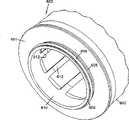
图6是图1组件的主过滤器筒部件的侧视图;Figure 6 is a side view of the main filter cartridge component of the assembly of Figure 1;
图7是图6所示的过滤器筒朝向端部58观看的端视图;Figure 7 is an end view of the filter cartridge shown in Figure 6 looking towards
图8是图6-7所示的过滤器筒的部件的立体图;Figure 8 is a perspective view of the components of the filter cartridge shown in Figures 6-7;
图9是图1所示组件的外壳部件的端视立面图,显示一移去的端盖部件和可见的某些内部部件;Figure 9 is an end elevational view of the housing components of the assembly shown in Figure 1, showing an end cap component removed and certain internal components visible;
图10是沿图9中的线10-10截取的图9的外壳部件的侧视截面图;10 is a side cross-sectional view of the housing component of FIG. 9 taken along line 10-10 in FIG. 9;
图11是图1的组件的一安全元件部件的侧视立面图;Figure 11 is a side elevational view of a security element component of the assembly of Figure 1;
图12是沿图11中的线12-12截取的图11的安全元件部件的侧视截面图;12 is a side cross-sectional view of the security element component of FIG. 11 taken along line 12-12 in FIG. 11;
图13是图11的安全元件部件的分解的视图;Figure 13 is an exploded view of the security element components of Figure 11;
图14是根据本发明的一空气清洁器的另一实施例的侧视立体图;Figure 14 is a side perspective view of another embodiment of an air cleaner according to the present invention;
图15是根据本发明的一空气清洁器的第二实施例的局部的立体图;15 is a partial perspective view of a second embodiment of an air cleaner according to the present invention;
图16是根据本发明的一空气清洁器的第三实施例的一部分的端视图;16 is an end view of a portion of a third embodiment of an air cleaner according to the present invention;
图17是沿图16中的线17-17截取的侧视截面图;Figure 17 is a side cross-sectional view taken along line 17-17 in Figure 16;
图18是图17所示的结构的一部分的放大的局部视图,一安全元件安装在其中;Figure 18 is an enlarged fragmentary view of a portion of the structure shown in Figure 17 with a security element installed therein;
图19是根据本发明的一空气清洁器的第四实施例的立体图;19 is a perspective view of a fourth embodiment of an air cleaner according to the present invention;
图20是用于根据本发明的一空气清洁器中的另一变化的主过滤器元件的一部分的局部的立体图;Figure 20 is a partial perspective view of a portion of a main filter element for another variation in an air cleaner according to the present invention;
图21是根据本发明的一变化的主过滤器元件的局部的截面图;Figure 21 is a partial sectional view of a primary filter element according to a variation of the present invention;
图22是根据本发明的另一变化的空气清洁器的立体图;Figure 22 is a perspective view of an air cleaner according to another variation of the present invention;
图23是图22的一部分的局部的截面图;Figure 23 is a partial sectional view of a portion of Figure 22;
图24是根据本发明的另一变化的空气清洁器的示意的立体图;Figure 24 is a schematic perspective view of an air cleaner according to another variation of the present invention;
图25是一分解的示意的立体图,示出图24的组件的一盖部件和一主空气过滤器元件筒;Figure 25 is an exploded schematic perspective view showing a cover member and a main air filter element cartridge of the assembly of Figure 24;
图26是图25所示的主过滤器元件筒的侧视立面图;Figure 26 is a side elevational view of the main filter element cartridge shown in Figure 25;
图27是图24所示组件的侧视截面图;Figure 27 is a side cross-sectional view of the assembly shown in Figure 24;
图28是根据本发明的空气清洁器的另一实施例的入口端的立体图;Figure 28 is a perspective view of the inlet end of another embodiment of an air cleaner according to the present invention;
图29是图28所示结构的分解的立体图;Figure 29 is an exploded perspective view of the structure shown in Figure 28;
图30是图29所示部件中的两个部件的立体图,从朝向一入口端盖的内表面的视点观看;Figure 30 is a perspective view of two of the components shown in Figure 29, viewed from a viewpoint toward the inner surface of an inlet end cap;
图31是图28所示组件的侧视截面图;Figure 31 is a side cross-sectional view of the assembly shown in Figure 28;
图32是用于图28-31的组件内的主过滤器元件部件的侧视立面图;Figure 32 is a side elevational view of the main filter element component used in the assembly of Figures 28-31;
图33是用于图32所示的主过滤器元件内的外构架部件的立体图。33 is a perspective view of an outer frame member used in the main filter element shown in FIG. 32. FIG.
具体实施方式Detailed ways
本发明涉及一空气过滤器结构。提供对于现有技术的空气过滤器的各种改进。诸般提高中的各种改进或选择的改进可用来提供给一有效的空气过滤器。示于图1-13的特定的空气过滤器,以及图14-33的变化的空气过滤器示出或演示本文所述的许多的各种提高的实例。在本发明的技术和原理的任何的和所有的实践中,不要求所述所有提高需被使用。许多特征描述在共同拥有的共同未决的下列美国临时申请中:2002年10月28日提交的60/421,882和2003年3月6日提交的60/453,737,两个表明为美国临时申请各被本文援引以供参考。The present invention relates to an air filter structure. Various improvements over prior art air filters are provided. Various or selected improvements of the various enhancements can be used to provide an efficient air filter. The particular air filter shown in Figures 1-13, and the variant air filter of Figures 14-33 illustrate or demonstrate many examples of the various enhancements described herein. In any and all practice of the techniques and principles of the present invention, not all enhancements described need to be used. Many of the features are described in the following commonly owned co-pending U.S. provisional applications: 60/421,882, filed October 28, 2002, and 60/453,737, filed March 6, 2003, both identified as U.S. provisional applications This article is incorporated by reference.
I.通用空气过滤器结构和操作I. General Air Filter Construction and Operation
图1中标号1总的表示根据本发明的一空气清洁器组件。所示特定的空气清洁器组件1是一内燃机的吸入空气的空气清洁器组件2。本文所述的许多技术可用于过滤或清洁各种气体。然而,所述细节特别用于一空气清洁器组件,例如,用于清洁内燃机的发动机吸入空气,所述内燃机是诸如卡车、公共汽车用的车辆发动机,或拖拉机或建筑设备用的发动机;或用于发电机的发动机。
参照图1,空气清洁器组件2一般地包括一外壳3,其具有一空气入口5;一空气出口6;以及一灰尘弹出或下落管7。空气清洁器组件2还包括便于安装的可供选择的安装腿或支承8。(或者,组件2可用分离的安装带或支架安装)可以设想在使用中图1所示的用于外壳2的通常定向一般地将为水平方向(即,如图1所示,管6水平地延伸,使下落管7指向下)。然而,本文中所述的许多原理和技术也可应用于沿其它定向安装的空气清洁器组件。Referring to FIG. 1 , the air
所示特定外壳2具有一大致圆柱形的外壳侧壁9;即,侧壁9的截面基本上为圆形。所示实施例的空气入口5是一侧边入口5a,即,入口5a通过侧壁9。具体来说,入口5是圆形切向入口10。文中术语“切向”意指圆形入口10的中心线11不朝向外壳3的中心线12(图3),但中心线11更加朝向切向。这将造成通过切向入口10进入的空气(图3中由此朝向区域14)开始以旋涡的方式运动。较佳的大致圆柱形形状的侧壁9促使该旋涡方式的运动。The
仍参照图1,空气出口6是圆形沿轴向的出口15。文中的所谓“轴向”是意指图3的出口15的中心线平行于外壳3的中心线或轴线12延伸。在所示的特定的实例中,出口15的中心线与外壳3的中心线12同轴,因为较佳的外壳侧壁9具有圆形的截面,出口6不偏心地定位。当然,其它变化的结构也是可行的,但该特定的结构比较方便。圆形的参考入口15是为了表示空气流动通道内部的通用形状。Still referring to FIG. 1 , the
参照图3,侧壁9分别具有相对的第一和第二端16和17。第一端16被盖18关闭,该盖具有从中突出的出口6。参照图3,盖18与端部16连成一体(不与其分离),在所示的优选结构中,盖18具有至少两个(在此实例中至少三个)不同直径的区域或台阶18a、18b和18c。对应的内直径或台阶逐步减小,即,18a>18b>18c。这些台阶的功能将从以下的讨论中得以理解。Referring to Figure 3, the
出口管6内的接头6a用来附连可供选择的压力或限制指示器或其它的设备。A fitting 6a in the
对于所示特定的实施例,灰尘下落管7邻近于第一端16。For the particular embodiment shown, the
图1中,端部17形成一敞开端,空气清洁器2包括邻近的入口5。侧壁19内的敞开端17被盖20关闭而允许空气通过其间。In FIG. 1 , end 17 forms an open end, and
一般来说,盖20在端部区域20a内没有通过其间的孔,并是一可移去的进口、或是安装在侧壁9上以关闭端部17的维护盖21。维护盖21定期地打开或移去,以提供进入外壳3的内部23的维护进口(图3),以便进行检测、保养或安装内部的部件。对于所示的特定的实施例,维护盖21从侧壁9完全移去,以形成进入内部的维护进口。盖21可用各种方式固定到外壳3的其余部分25上(图10),例如,利用门闩、螺栓或其它的结构。图中示出若干个方便的安装机构并在下文中作详细讨论。In general, the
现将注意力集中到图2中来。在图2中,空气清洁器组件2示于一分解的立体图中,这样,可以看到某些分离的部件。参照图2,所示部件包括:外壳部分25(即,没有盖20的外壳3);维护盖21;一可移去和可更换的副安全过滤器元件或筒31;以及除尘器阀32(用虚线表示,移去而未可见)。主筒30显示在图6的侧视图中;而安全筒31显示在图11的侧视图中。除尘器阀32可移去,但在空气清洁器2的正常使用中,一旦阀32安装好,其不再移去,除非其变得损坏。Now focus on Figure 2. In Figure 2, the air
仍参照图2,空气清洁器组件2还包括一预清洁器35。一般来说,诸如预清洁器35那样的预清洁器操作而从空气流中去除某些颗粒材料,然后,空气流才通过主空气过滤器元件或筒30的介质。这样做的优点在于,它提供主过滤器筒30的较长的使用寿命。对于所示的特定的结构,预清洁器35固定到维护盖21,在正常的较佳的操作中,其决不分离,且的确是不可分离的,对盖20不造成损坏。在一变化的实施例中,下面结合图21进行讨论,预清洁器安装在和固定在主过滤器元件或筒上。Still referring to FIG. 2 , the air
参照图5,预清洁器35包括:一气旋的坡道部件36;以及一大致圆柱形的屏蔽部件37;使坡道36定位在屏蔽部件37的外表面42上。在所示实施例中,坡道36和屏蔽37彼此形成一体,两个模制在一起形成为单一的塑料部件。在坡道36后面的端部36a、区域36b处(即,坡道36和盖20的端部20a之间),坡道36被端部38关闭。部件36、37(和由此的预清洁器35)的操作部分地将参照空气清洁器组件2的一般操作得以理解。5, the pre-cleaner 35 includes: a
在正常操作过程中,待过滤的空气通过切向入口10(图1)进入空气清洁器组件2,到达图3中的空间14内。该空间14一般形成在(外壳侧壁9的)内表面41和(屏蔽37的)外表面42之间。进入空间14内较佳地是进入图5中的区域43a、43b之一内,其中,坡道36基本上还没有逐渐地远离端部20a。因为较佳的切向进口,朝向空间14的空气流基本上引入一圆形的周向或旋风的气流。对于所示的特定实施例,参照图1的总图,当从空气清洁器2的外面朝向盖20观看时,该气流将是顺时针方向的。当然,空气清洁器组件2也可构造成相对方向的流动。During normal operation, air to be filtered enters the air
再次参照图3,在进入空间14后,空气引导入预清洁器35内。旋风的坡道36定位成帮助对空气形成一螺旋的或气旋的力矩,当空气围绕屏蔽37打圈时,灰尘被携带在其中并螺旋地朝向端部16。一般来说,坡道36围绕屏蔽37盘圈不到一整圈,较佳地不大于340°,通常小于320°,例如,在150°至280°的范围内。一典型的屏蔽37至少突出35mm(毫米),沿元件筒30的侧面通常为44mm至170mm。一典型的坡道36至少突出5mm,通常从屏蔽37向外突出7mm-20mm。Referring again to FIG. 3 , after entering the
屏蔽37防止携带颗粒的空气在螺旋(和由此的预清洁)发生之前就立即撞击到筒30内的介质。一般来说,由于气旋的作用,携带在空气流内的相当部分的灰尘颗粒将朝向外壳25的内壁41,最终通过灰尘下落管7弹出。在一典型的结构中,灰尘下落管7被弹出阀32(图1和2中用虚线表示)盖住。这样的弹出阀是公知的。某些实例描述在美国专利3,429,108中,本文援引其全部内容以供参考。
在一典型的实施例中,坡道36以每10°转动提供离端部43约2mm至4mm的线性运动或距离的速率旋转。In an exemplary embodiment,
参照图3和5,一般来说,主元件或筒30包括一延伸的介质55,它环绕和形成一中心的清洁空气的体积56。对于所示特定的实施例,介质55布置成多个打褶55a,它们在筒30的端部57、58之间沿纵向延伸。Referring to Figures 3 and 5, generally speaking, the main element or
再次参照图3,空气在退出预清洁器35之后,从上游侧59到下游侧60通过主筒30,然后,进入清洁空气区域56。此点的空气通常足够清洁,可通过出口管6前进到内燃机的发动机/空气吸入口。Referring again to FIG. 3 , after exiting the pre-cleaner 35 , the air passes through the
如上所述,所示特定的空气清洁器组件2包括一可供选择的副或安全元件或筒31(图2)。安全元件或筒31包括定位在图3的区域56内介质65,这样,退出介质55的空气在前往出口6的途中必须通过介质65。典型应用中的介质65不是打褶的,相反地包括片状的无纺含纤维的介质,其围绕敞开的中心区域66(图3)。As noted above, the particular air
从以上描述可知,空气清洁器组件2的一般操作将可理解如下:From the above description, the general operation of the air
1.待过滤的空气首先通过入口5进入组件2。1. The air to be filtered first enters the
2.通过组合切向入口、圆形外壳侧壁9、屏蔽37和预清洁器坡道36,空气流形成气旋或螺旋的流动形式。这驱动某些灰尘材料对着外壳侧壁9的内表面41,由此提供一预清洁的效果。预清洁的灰尘最终通过下落管7弹出。2. By combining the tangential inlet, the circular
3.空气通过主过滤器筒30的介质55并由此被过滤。3. Air passes through the
4.如果采用可供选择的安全或副过滤器筒,则过滤的空气通过安全或副过滤器筒31的介质65,进入清洁空气区域66。4. If the optional safety or secondary filter cartridge is used, the filtered air passes through the
5.然后,空气从空气清洁器2通过端盖18,即,通过出口管6沿轴向引导向外。5. The air is then directed axially outwards from the
再者,优选的空气清洁器组件2的某些一般的结构特征归结如下:Again, some general structural features of the preferred air
1.进入盖20位于离开空气流出口管6的外壳3的相对端17处。1. The
2.入口5是一侧向进入的入口,而出口6是一轴向的气流出口。2. The
3.入口5位于外壳的邻近端17,出口管6位于外壳3的邻近的相对端16。3. The
4.用于灰尘的下落管7位于邻近的出口管6和外壳的端部16。4. A
5.预清洁器35位于外壳的端部17处的邻近入口管5,以及由此邻近盖20。5. The pre-cleaner 35 is located at the
6.对于图3的特定实施例,预清洁器35永久地安装在盖20上。6. For the particular embodiment of FIG. 3 , the pre-cleaner 35 is permanently mounted on the
II.空气清洁器2内的主过滤器筒30的密封II. Sealing of the
如上所述,主过滤器筒30是可移去和可更换的(即,维护的)部件。即,为了便于维护(例如,进行更换)主过滤器筒30构造成可移去。为了确保空气清洁器组件2合适地操作,因此,一旦安装主筒30必须构造成合适地密封在外壳3内,以使空气在操作过程中不旁路通过介质55。空气清洁器组件2可以构造成以各种方式提供该种密封。As noted above, the
例如,可使用围绕出口端的主筒30的内部或外部和组件的另一部分之间的径向密封。适用于包括具有如上所述某些特征的部件的空气清洁器的各种类型的径向密封系统,例如,示于PCT出版物WO89/01818中的259和美国专利5,938,804的图6中的75;本文援引这两个参考文献以供参考。显示在这些结构中的径向密封的类型经合适的改型就可适用于本文所述的系统内。一个径向密封显示在图20的变化的实施例中,下面将讨论该实施例。For example, a radial seal between the interior or exterior of the
然而,所示特定的空气清洁器组件2使用主过滤器筒30和空气清洁器2的其余部分之间的一较佳的轴向密封,使得优点尤为突出。文中术语“轴向”意指这样的密封,在密封压力下密封沿图3中的箭头68的方向,即大致平行于元件和外壳中心轴线12的方向操作。However, the particular air
具体来说,参照图3,外壳侧壁9的端部16被带有出口6的端盖18关闭。端盖18的内表面69围绕空气流出口孔69a构造为一密封表面。即,正是在该表面69处轴向密封形成在主筒30和外壳3之间。In particular, referring to FIG. 3 , the
参照图5和6,主过滤器筒30的端部57包括一具有密封材料的圆形突脊、突出部或肋70的端帽57a,密封材料的肋大致围绕敞开的中心气流出口孔71。图3中的密封肋70压靠在表面69上,围绕孔69a而形成轴向密封。较佳的肋70在如图3所示的压缩之前具有一略微的三角形截面。Referring to Figures 5 and 6, the
示于图1-13中的特定的结构使用一具有优点的结构来压迫肋70抵靠表面69,形成主元件30的轴向密封。这将在下面第IV节中详细讨论,其中,提供一关于主过滤器筒30的详细讨论。The particular construction shown in FIGS. 1-13 uses an advantageous construction to press the
一般来说,因为PCT出版物WO89/01818中描述类型的内径向密封不使用在较佳的空气清洁器组件2内,所以外壳3在端部16处可做成没有任何内部的、轴向的突出的径向密封管或圆柱形构造(如果要求的话)。还有,因为主过滤器筒30没有如美国专利5,938,804中75处所描述类型的任何外径向密封,所以,用于图3的优选实施例的外壳侧壁9可做成没有用于外周缘径向密封的任何其它所必须的环形密封表面。In general, since an inner radial seal of the type described in PCT publication WO89/01818 is not used in the preferred air
III.可供选择的安全筒31的密封III. Sealing of
参照图2,安全元件或筒31包括相对的第一和第二端80和81。在组装过程中,第一端80是朝向出口6插入的端部。端部80包括与其相邻和间隔开的安装的O形环84。参照图3,当安装在组件2内时,端部80推入到端盖18的环形的圆柱形突出部85内,使O形环84在筒31和端部18(具体地为部分18c)的环形内表面之间提供一密封。由O形环84提供的密封确保不希望的空气层不通过出口6,从而不通过安全元件筒31。应该指出的是,由O形环84提供的密封通常不是关键的,因为主过滤器筒30的密封主要保护发动机避免不理想的(未过滤的)空气流。Referring to FIG. 2 , the security element or
副筒或安全筒31通过其而固定在位置上的特定机构以及副筒31的其它特征将在下面第VI节中描述。The particular mechanism by which the secondary cylinder or
IV.主过滤器筒30IV.
现将注意力集中到图6中来,其中,主过滤器筒30显示在侧视图中。一般来说,过滤器筒30包括:一介质和密封支承结构90;介质55;以及相对的第一和第二端帽92和93。通常端帽92定位在主过滤器筒30的端部57处;而端帽93定位在端部58处。介质55完全地在端帽92、93之间延伸。对于所示特定的实施例,支承90也完全地在端帽92、93之间延伸,但在某些变化的实施例中这样的延伸可以不是完全的。Attention is now directed to Figure 6, where the
图6中示出特定的优选主过滤器元件或筒30,其通常用于空气清洁器2中,主过滤器筒30没有一内部的过滤器衬垫或支承,其在端部57、58之间完全地延伸并安装为一筒30的不可分离的部分。相反,选择地通过不安装在和不设置为主筒30的不可分离的部分(将在下文中描述),提供基本上沿介质55的全长的内部支承(例如,除一端或两端外)。较佳地是,对于介质设置某些内部支承,其为筒30的部分或为分离的部件,但较佳地是一分离的部件。A particular preferred primary filter element or
一般来说,端部57是一敞开端,其中包括一孔71,在过滤操作过程中该孔用于空气的流出。另一方面,端部58是一关闭的端,意味着在正常操作过程中空气不能通过被端帽93盖住的端部58。从下面的讨论中将可理解以优选的方式为此提供的诸特征。Generally, end 57 is an open end which includes a hole 71 for the egress of air during filtering operation.
介质和密封支承结构90示于图8中。支承结构90示于图8,其上没有介质或端帽。因此,示于图8中的支承结构90是一用来制造图6中的筒30的部件。在筒30中,支承结构90通常不分离或移去,不对筒30造成损坏。The media and seal
从图1-3和8中可以明白到,较佳的筒30是一“非连续的螺纹”筒。其意味着在优选实施例中在筒30的任何部分上没有连续的螺纹,用来将筒螺纹地安装、固定或附连到空气清洁器2的任何部分上(例如,连续地转动或通过360°或以上的所要求的转动)。As can be seen from Figures 1-3 and 8, the
参照图8,支承结构90包括一第一端100和一第二端101。第一端100通常形成一没有构架的圆形开口102。圆形开口102(在完成的元件30内是孔71)为过滤后的空气提供一出口区域(或出口)。一般来说,端帽92(图6)模制在端部100上,以在此端对介质55提供封口。在一典型的优选实施例中,端帽92还形成密封肋70和空气出口孔71。通常,为了达到这一点,端帽92由一合适的可压缩的聚合物材料形成,例如,如下文中描述的泡沫的聚氨酯。Referring to FIG. 8 , the
参照图3,较佳的密封肋70定位在沿轴向与支承90的边缘100a对齐,或定位在沿径向离边缘100a的内部。通常地,它将定位在沿径向离边缘100a的内部,使其峰不超过边缘100a内的约10mm。其结果,通过支承90的边缘100a或介质55的打褶端部,或其两者,肋70通常被驱动朝向表面69而形成一密封。Referring to FIG. 3, the
参照图8,支承结构90包括邻近端100、屏蔽105。屏蔽105通常是支承结构90的一部分,该部分未打孔或空气在其间不透气。屏蔽105的尺寸(图3)适于重叠孔7a,那里,灰尘下落管7与侧壁9的其余部分相遇。当灰尘流向管7a时,这阻止灰尘在此区域内以不理想的方式直接撞击介质。空气可在屏蔽105下面到达边缘105a处,在此区域与介质55相遇(图3)。Referring to FIG. 8 , the
现将注意力集中到图6中来。在图6中,可供选择的沿轴向突出的环或肋105b用虚线示出。这样的环105b可以是一沿径向向外突出的连续环,其围绕屏蔽105。通常地和较佳地该环105b与屏蔽105的其余部分一体形成。可供选择的环105b较佳地邻近于下文描述的安装结构129的部分但与其隔开,以阻止不希望的灰尘层运输到该安装结构129内。这将在下文中作详细描述。Now focus on Figure 6. In Figure 6, an optional axially protruding ring or
对于所示特定的实施例,支承90完全地在端部100和101之间延伸;而在图8中则在屏蔽105和端部101之间延伸,支承90包括一打孔的或敞开的部分106。这意味着在区域106中,支承90包括构架107,其留下相当的敞开区域108用于空气通过其间以与介质相遇。较佳地,在此区域106内,构架107至少50%敞开,尤为较佳地至少70%敞开。由此,这意味着区域106的总面积至少50%和更佳地至少70%被孔或开口所占据(相对于实心构架而言)。较佳地,无孔屏蔽105占据端部100和101之间的支承90的全部延伸(长度)的至少10%,但不占据40%以上。较佳地,打孔部分106占据支承90的全部轴向长度的至少20%,尤为较佳地至少60%。For the particular embodiment shown, the
仍参照图8,所示较佳的构架107包括多个径向间隔开的轴向肋109,在此实例中,10个等距离沿径向间隔开的这样的肋(通常为6-14个这样的肋)与圆周方向螺旋形的径向肋结构109a交叉连接,在此实例中,两个连续的螺旋109b从邻近端部101的大约点109c(沿径向约间隔180°)延伸到邻近屏蔽105的点109d(沿径向约间隔180°),各个螺旋具有约720°的总的径向延伸。相对于一系列平行的径向肋,该螺旋形肋结构109a的优点在于,当构架107在密封一未密封的筒30的过程中置于径向应力下时,可提供构架107的抗扭转的能力。可用另一种变换方式来描述径向肋109的螺旋形打转,即,径向肋从垂直于中心轴线12(图3)转过角度至少约为10°,通常的角度在15°至45°范围之内。这可变换地表述为锐角B(图6)。Still referring to FIG. 8, the
现将注意力集中到图8中的端部101。一般来说,与端部100处的开口102相比,端部101包括交叉延伸的端部构架110。构架110不完全关闭端部101,但相反包括如下的一般特征:中心的、不贯穿的区域111;以及环形敞开的构架112。Attention is now directed to end 101 in FIG. 8 . In general,
仍参照图8,环形敞开构架112通常包括在不贯穿区域111和端部101之间延伸的辐条113(在此实例中8个辐条,通常为3-11个辐条);以及互连辐条113的圆形的结构肋114。由结构112形成的开口115帮助提供较佳的主元件30的制造(将在下文中描述)。Still referring to Figure 8, the annular
在主元件30的较佳的制造过程中,可提供一包括支承90的预制的、模制的塑料部件。打褶的介质将通过开口102放入支承90内。打褶的介质充分地向内插入,使介质的一端部抵靠在构架112上。区域111内的凹陷表面111a朝向端部102突出,使介质围绕着它,以在其周围形成接纳环形介质的沟槽116,帮助将介质的插入端保持成圆形形状。During the preferred manufacture of the
然后,构架90的端部101可放置到一模具内,模具包括一可固化的聚合物材料。该聚合物材料将流过构架112进入到介质褶的端部内,以形成罐封(如图6中端帽93所示)。这将密封关闭褶的端部,将介质固定到位并关闭开口115。一般来说,罐封材料和模具深度已作选择,使罐封材料不到达凹陷区域111的表面111a。从端部101起的表面111a的凹陷深度通常至少约为3mm,一般不大于7mm,例如,4-5mm。The
现将注意力集中到图4,图中示出通过这样一过程形成的端帽93。罐封的材料通常表示为标号120。由此可见,尽管区域111未被罐封材料120覆盖,但保持的构架112已被覆盖。对于图4所示的特定的结构,模制的罐封材料120显示为由模具支座形成的环形、径向间隔开的下陷。Attention is now directed to Figure 4, which shows an
端帽93则为一复合的关闭端帽58,使复合物大致包括:形成一环形无孔的罐封材料120、环;以及形成端帽93内的中心无孔表面的暴露表面111。
通过将端部100插入一第二模具内并在其上模制端帽92,由此可完成元件30的制造。在插入到第二模具内的过程中,可防止介质55通过孔102落出,因为通过第一模制过程介质已经在构架112上锚固到位。Manufacture of
优选实施例的主过滤器筒30包括其上的结构,其在使用过程中提供对筒30在组件2内的固定到位。对于所示的特定优选的结构,安装结构设置为支承90的一体部分;然而,其它的变化形式也是可能的。该结构部分地可通过图8中的支承90得以理解。The
在图8中,示出提供固定筒30的安装结构129,其具有压靠在图3中的表面69上的密封材料70(图3)。所示的特定的安装结构129是非连续的螺纹的转动接合机构129a的部分,部分地通过赋予过滤器筒30上的转动的力矩,它的操作将密封材料70压靠在表面69上。在锁定和安装过程中正是这种对筒30提供径向扭转的操作,才使得通过提供带有螺旋结构109a的支承90得到便利。所示优选的结构构造成转动不大于50°,较佳地不大于30°,尤为最佳地是20°或不到,这是从打开锁定位置到锁定位置所必须做的。这从以下的描述中将会得到明白。In FIG. 8 , there is shown a mounting
接合结构129a一般地随筒30的一部分接合而进行操作,经转动后其接合外壳部分25上的一部分。参阅图8将可理解一特定的互相作用的实例,具体来说,是沿径向向外突出的环130,其操作为在筒30上的安装结构129。
所示实施例中的径向突出的环130是一分段的环131。所示特定实施例包括四个相同的均匀间隔开的分段131a;然而,也可采用其它变化形式。在图5中,可以看见三个分段132、133和134。第四个分段135也定位在图5中。在图7中所有四个都可见。各个分段131a从支承90的一直接邻近的部分沿径向向外突出至少2.5mm,通常至少为3.5mm。The
参照图8,分段环131具有一系列径向间隔开的间隙136。诸间隙136定位在分段环131的分段132-135之间。间隙136尺寸适于使环131的至少选定部分推入(轴向地)通过外壳9内的结构特征,以实现如下所讨论的转动接合。各个间隙136较佳地至少为6mm宽,通常至少为7mm宽。例如,在20mm-40mm量级上的间隙是可用的。Referring to FIG. 8 , segmented
参照图8,各个环分段131a(诸如分段133)包括相对的第一和第二端140和141。端部141通常是一钝端;而端部140包括一短的分段142,其朝向端部100与分段131的其余部分143轴向地偏移。其结果形成一面向端部101(或远离端部100)沿着分段142的表面146的接纳区域145。接纳区域145定位成接合(径向接纳)外壳9内的结构(下文中讨论),以在操作过程中确保主元件30和外壳9之间的合适的密封。应该指出的是,部分140的末端147做成一倒圆的尖端,使表面145成为一凸轮表面,其从朝向端部101的尖端凹陷并朝向部分143延伸。还应指出的是,各个环分段132-135的定向应使其对应于部分142的偏移部分(图8)位于间隙136的一侧上,而对应于下一个邻近环分段的端部141的钝端定位在对应间隙136的另一侧上。在所示的实例中,从端部101观看的端视图中,各个分段131沿顺时针弧“指向”,端部141被看作是前端。Referring to FIG. 8 , each
现将注意力集中到图10。在图10中,示出外壳9的部分25的截面图。在图10中,示出保持器结构150。从图9和10中可见,对于所示特定的实施例,有四个均匀地间隔开的保持器结构150,各对应于环130内的一个间隙136。Focus now on Figure 10. In Fig. 10, a cross-sectional view of
各个保持器结构150在邻近外壳侧壁9的部分18b的区域处(在部分18a和18b之间的连接区域处)邻近外壳9的内表面41定位。各个保持器结构150的尺寸适于通过一间隙136(图8);此外,朝向出口6的表面151的形状为一凸轮,其从末端150a朝向出口6倾斜。最后,保持器150包括位于与末端150a相对的一端处的端部阻挡152。Each
从图9的视点出发,即,朝向端部17观看,如果假定末端150a是各保持器的前端而阻挡152是后端,则各个保持器“指向”逆时针。指向该方向便于与分段131接合,如以上所表征的,它指向一相对的方向。应该指出的是,如果环分段131构造成指向逆时针,则保持器150会指向顺时针方向。(上述的和其它变化的结构将从下面对操作的描述中得以理解)。From the point of view of Figure 9, ie looking towards
尽管其它的变化也是可能的,但在所示特定的实施例中,外壳3包括对应于保持器150的四个保持器,它们围绕表面部分18b的内部沿径向均匀地间隔开,各定位在相同的方向。再者,四个保持器150通常对应于四个环分段132-135之间的四个间隙136。Although other variations are possible, in the particular embodiment shown, the
现在可以明白造成垫片70和表面69之间密封的主过滤器筒30和外壳3之间的操作接合。一般来说,筒30将通过图10中的开口端17插入敞开的外壳25内。首先插入的元件30的端部是图6中的端部57。筒30将继续推入,取合适的径向定向以使保持器150可通过间隙136。这将使垫片70遇到图3和10中的表面69并压靠在该表面上。一旦达到这样程度的插入,筒30转动(对于特定实施例显示为顺时针),以使各环分段的部分142对齐在各个保持器150的表面151上。各个部分142的表面145和各个保持器150的表面151、即接合表面的形状和尺寸造成进一步的偏置或凸轮方式驱动筒30抵靠表面69,较佳地是使肋70压缩,以确保垫片材料70合适地压缩而形成一密封。较佳地设计转动直到末端147接合阻挡152。The operative engagement between the
由于转动互锁的结果,保持器150定位抵靠表面146,不转动的话,则筒30不能返回离开表面69。As a result of the rotational interlock, the
参照图10,在末端150a和阻挡152之间的大致弧长内,呈现筒30的全锁定和全脱开锁定之间的转动弧。通常该结构应使弧不大于70°,一般地不大于50°,对于图10的特定实施例,较佳地不大于40°。对于图10的实施例,最为较佳地是不大于30°。的确,对于所示特定实施例,该弧仅在10°至25°的量级上。Referring to Figure 10, within the approximate length of the arc between the end 150a and the
从以上可见,对于所示特定实施例,主过滤器筒30不包括沿介质55的内表面在端部57、58之间延伸的内支承结构。这对于制造和组装是有利的。当筒30在使用中定位在一空气清洁器内时,通过已经定位在外壳3内的结构设置介质55的内支承。From the above it can be seen that, for the particular embodiment shown, the
具体来说,通过图2中的一分离的支承结构160、例如副或安全元件或筒31的一部分来提供介质55的内部支承。In particular, internal support of the
在操作的副或安全元件31不使用在系统内的情形中,一类似于结构160但不具有作为副过滤器的与其相连的介质的支承结构,可用来沿着其内部支承介质55。In cases where the secondary or
再次将注意力集中到图6所示的可供选择的肋105b。这样一肋105b在使用中通常从安装结构129朝向端部93沿轴向间隔地定位,具体来说,从分段的环131沿轴向朝向端部93。较佳地,可供选择的肋105b离分段环131的间距沿此方向不大于10mm,较佳地基本上小于10mm。连续环105b通常在使用过程中保护分段环131免于不理想地暴露在灰尘中。Attention is again directed to the
在某些变化的实施例中,可以要求构架90从端部100到端部101不连续地延伸;但可使支承90包括屏蔽105,而没有在端部101处的构架;并且在相对端101处具有合适的结构(诸如不透气的区域111和环形敞开构架112),以形成一较佳的复合端帽。In some variant embodiments, the
V.端盖20
如上所述,端盖20是一维护用盖21,其可从外壳的25的其余部分移去,以允许进入外壳内部23进行维护保养。As mentioned above, the
对于所示特定的实施例,端盖20没有延伸通过其间的气流孔。即,它具有外表面20a(图1)和内中心表面20b(图5),没有孔或气流管延伸通过其间。为此原因,它可以被称之为“关闭”或“完全关闭”的端盖20。For the particular embodiment shown,
参照图1、2和4,组件2包括一安装和锁定机构170,以将盖21固定到外壳侧壁9的其余部分25上。一般来说,安装和锁定机构170包括多个安装在外壳侧壁9和盖20之一上的柔性接片,多个安装在外壳侧壁9和盖20之另一个上的接合凹陷。对于所示特定结构,安装和锁定机构170通常包括多个在端盖21上的柔性接片171,各个接片包括一沿径向突出的舌头172(图4)。对于所示特定的实施例,安装机构170包括两个接片171a、171b,它们围绕盖21的圆周沿径向间隔开180°。外壳侧壁9包括一对凹陷或槽175(图1),当安装维护盖21时,用来接纳舌头172。Referring to FIGS. 1 , 2 and 4 , the
接下来,操作如下:参照图1,为了从外壳3的其余部分移去维护盖21,接片171朝向彼此偏置。这可将突出的舌头172移出槽175(图4)而释放盖21,以便相对于外壳侧壁9运动。插入则是一相反的操作。下面讨论用来形成盖21的特定有用的材料以形成柔性接片171。如果舌头172在朝向外壳其余部分25的端部上设置有合适的凸轮表面,则在安装过程中,当盖20压入就位时,其不需用手偏置接片171,但相反当盖20压入就位时凸轮将造成偏置或卡入的配合安装。Next, the operation is as follows: Referring to FIG. 1 , in order to remove the
所述特定安装和锁定机构170的优点在于,它包括与盖20和外壳9集成在一起的诸特征,在盖20模制之后,为了操作,它部分不需要附连诸如门闩、钩等之类的任何附加的机构。The advantage of this particular mounting and
对于所述特定的安装系统,仅使用两个接片171和槽175;而各个接片171可与各个槽175接合。其结果,就如以上所述,盖21相对于侧壁9可沿两个转动定向安装。然而,如果这对于所述特定实施例是可能位置的话,则盖20会安装成使入口5和坡道36之间的定向不合适。为了确保盖20相对于外壳25的其余部分仅安装在单一转动位置上,可设置一指示结构。具体来说,可利用一槽和键的结构,其中,一个部件(槽或键)定位在盖上;而另一个部件(槽或键)定位在外壳侧壁9上。两个部件定位成:当盖转动到一特定的预设定向时,盖可唯一的配合(槽接合键)。For this particular mounting system, only two
一如图15的实施例所示的实例,其中,盖700显示为安装在侧壁701上,使位于盖100上的键或销702被接纳在侧壁701上的槽703内。如果键或销702与槽703对齐,则盖700才可以合适地安装。因此,示于图15中的槽和键结构705确保盖700相对于外壳侧壁701合适地可转动地安装,以便于合适地操作。An example is shown in the embodiment of FIG. 15 , where
再次参照图1,图中用虚线示出一在盖20上的手柄结构710。如果要求的话,接片171和槽175可以构造成:在手施加到手柄710上的力(拉力)的作用下,(即,拉动手柄710),盖20可从其固定位置释放,不需手工地压迫接片171朝向彼此。手柄710可构造成各种形式。所示特定的手柄710包括一可移去或可更换的交叉部件,其在两个安装耳712、713之间延伸。耳712、713可以与盖20的其余部分一体地模制而成。Referring again to FIG. 1, a
现将注意力集中到图5,讨论盖20上的屏蔽37内的细节。尤其是,在使用中将邻近端部58的屏蔽37的内部的部分中,盖20包括一内直径比屏蔽37的其余部分179a小的内部环179。图3中的环179a的尺寸适于在使用中接纳其中的端部58,使其间很少或没有间隙。这将有助于可靠地沿端帽93支承主筒30的端部58,即,远离出口6的筒30的端部。Attention is now directed to FIG. 5 to discuss details within
参照图6,通过安装结构129和端帽92的组合,主过滤器筒30支承在外壳3内的端部57处(图3)。Referring to Figure 6, the
参照图4,现将注意力集中到一接合结构上,以便在主元件30和盖20之间提供一较佳的接合。尤其是,并参照图4,主过滤器筒30内的不透气的区域111包括在预成形内的凹陷表面111a,该预成形包括构架90的一部分,不透气的区域111还包括中心定位在表面111a内的突出部/接受器结构184的一第一部件183。尤其是,表面111a包括接受器185。较佳地,接受器185是非圆的,其原因将在下文中讨论。对该实施例所示的特定的接受器185显示在图4中,它是一X形(或“十”形)的接受器186,在X形的各对相邻臂的中心线之间形成一90°角,但也可采用各种变化的形状。X形状对于接受器186带来的特别的优点将在下文中对于指示性和对称性进行讨论。本段落文中的术语“预成形”是指罐装到端帽内之前所制造的端帽的结构部件。Referring to FIG. 4 , attention is now directed to a joint structure to provide a better joint between the
此外,如图5所示,盖20沿着其表面190的内部包括突出部/接受器结构184的一第二部件187,在此实例中是中心定位的突出部191。再者,较佳地,突出部191是非圆的,在此实例中是一X形突出部192,在X形的各对相邻臂的中心线之间形成一90°角。突出部192的尺寸和结构在合适对齐时突出到接受器185内。当空气清洁器2组装时(图3),突出部191将突出到接受器185内。一部分因为突出部192和接受器186两者都是非圆的,所以,当空气清洁器端盖20锁定在外壳3上的位置时,通过突出部/接受器结构184,可防止筒30在使用中转动。Furthermore, as shown in FIG. 5 , the
尤其是,在使用过程中元件30相对于外壳3无意地发生转动,重要的是要确保维持垫片材料70和表面69之间的密封。即,元件30和表面69之间的相对转动将会趋于脱开保持器150和环分段131之间的相互作用。为了在组装和使用过程中阻止元件30相对于外壳3的其余部分的转动运动,突出部191和接受器185的形状应在转动后发生接合,并阻止筒30和空气清洁器25的其余部分之间的足够的相对转动运动,以使筒不密封。所示的特定形状各为一X形。然而,对于该一般的功能,全部所需要的在于,突出部191和接受器185是非圆的,但宁可是非圆的且有一部分与其他部分互相作用,并阻止一个相对于另一个作转动运动。In particular, should
用于各个部件的交叉或X形(或十形;即,“加号形”)的四个臂的特殊用途涉及一指示和对称的功能。尤其是,主过滤器筒30的环131包括一具体数量(N)的径向间隔开的间隙136。由于这样的结构,同样数量(N)的保持器150和同样数量(N)的分段131、筒30可在N个特定径向定向上定位在外壳3内。当N是数字4时,四个位置成90°分开,各个这些N个径向定向对应于突出部191的一个臂193。由于总数有四个间隙136、四个保持器150和四个分段131,所以,所示特定的突出部191是X形192,带有四个臂193各相对于相邻臂延伸在90°。当然,图4中的接受器185类似地进行构造。因此,元件可安装在四个转动位置。The special use of the four arms of the cross or X-shape (or ten-shape; ie, the "plus-shape") for each component involves an indicative and symmetrical function. In particular, the
在多个可能转动位置和接合之间,在主过滤器筒30和外壳3的其余部分之间的这种对称性将一般地被称之为主筒/外壳的转动对称性。对于所示特定的实施例,主筒/外壳的转动对称性是四个折叠,意味着四个转动定向,但主筒/外壳的转动对称性不大于四个也是可能的。当然,其他的变化也是可能的;然而,较佳地是提供至少两个可能的转动位置。This symmetry between the
突出的部件191延伸入突出部/接受器互锁结构184的凹陷或(预成形的)接受器185内的程度不是关键的,只要突出的程度足够阻止转动即可。可以预料在一般的结构中,其制成的从表面111a突出到接受器185内的量将至少为3mm,通常至少为5mm,一般在6mm至10mm的量级上。The extent to which the protruding
当然,突出的接受器结构183的第一部件可以相对于接受器突出,而第二部件作为接受器代替突出部。即,突出部/接受器结构184可以构造成其突出部从表面111a朝向盖20沿轴向向外延伸,以便被接纳在盖20上的一接受器内。然而,所示特定的实施例最好带有位于筒30上的接受器185以及位于盖20上的突出部191。Of course, the first part of the protruding
再者,应该指出的是,在端帽93(图6)的其余部分模制之前,不透气的端部111和构架112(图8)较佳地形成为一预成形。Again, it should be noted that the gas
参照图3,还应该指出的是,当盖20合适地安装时,较佳的盖20被外壳侧壁9包围;且盖20不包括在侧壁9的端部17的一外表面上的区域17a上(或围绕该区域)滑动的部分。以此方式构造的一盖20有时称之为以下的特征:“安装时,盖20定位成被外壳9的一部分围绕,当安装时,盖20不包括围绕外壳9的部分”,或由其变体来表征。下面将描述用来安装盖20的变化的结构。Referring to Figure 3, it should also be noted that the
VI.可供选择的安全元件31VI. Alternative
现将注意力集中到图11-13,涉及到可供选择的安全元件31。一般来说,图13中的安全元件31包括:支承160;内支承201;介质65;以及O形环84。支承160通常延伸在第一端80和第二端81之间。第一端80是在安装过程中首先插入外壳内部23内的端部。端部80包括与其间隔但邻近其安装的O形环84,其定位在O形环接受器203内。对于所示的特定实施例,端部80包括直接相邻的带有安装槽206的不透气的环表面205。安装槽206通常在图12中呈L形(或J形或钩形),并定位成在合适的接合和扭转之后接合位于外壳3内的短柱210(图9)。短柱210沿径向向内突出。(一变化的实施例在下文中描述,它不使用一槽206/短柱210的接合机构)。Attention is now directed to FIGS. 11-13 , which relate to an
对于图11-13中所示的特定结构,有两个槽206和两个短柱210,各对的各个部件围绕外壳3的内部从另一个起转动180°定位。短柱210在表面18c上。因此,外部支承160构造成在安装过程中相对于外壳3具有两个转动位置。支承160和外壳3之间的对称性通常称之为支承160/外壳对称性,或由其变体表征。带有两个可能位置但不多于两个的对称性将被称之为双折叠支承160/外壳对称性。For the particular configuration shown in Figures 11-13, there are two
再次参照图13,支承160包括带有孔212的构架211。较佳地支承160在端部80和端部81之间的延伸上至少50%敞开,且尤为较佳地至少70%敞开。在一般的使用中,安全筒31没有施加到其上的显著锁定扭转和压力,只是槽206和短柱210之间实施的互相作用。即,为使实施短柱210和槽206之间互相作用而作的转动相当容易。因此,支承构架211没有螺旋形的径向延伸,但相反使用互连轴向延伸214的平行的环213(在此实例中5个环)。Referring again to FIG. 13 , the
端部80一般地形成一敞开的圆形内部80a,在使用过程中空气可通过该圆形内部。另一方面,端部81被盖215盖住。对于所示的特定实施例,盖215包括一凹陷的中心216,其构造在下文中描述。The
对于图11-13中所示的特定的安全元件,介质65包括一无打褶的无纺材料的包裹或类似结构。它大致地定位在内支承201和支承160之间。参照图13,内支承201是具有相对的第一端和第二端222、223的大致的构架,并带有在其间延伸的敞开的或多孔的支承结构229。较佳地多孔结构229在该延伸上至少50%敞开,尤为较佳地至少70%敞开。对于所示特定的实施例,支承结构229是一系列沿径向间隔开的轴向延伸部229a,它们被平行的间隔开的环229b支承,在此实例中为5个环(不计端部229c)。For the particular security element shown in Figures 11-13, the
对于所示的特定实施例,内部支承201的端部222形成一敞开的圆形开口222a,以在使用过程中允许空气通过其间;而端部223被端盖225盖住。所示较佳的端盖225包括一凹陷的中心部分226。For the particular embodiment shown, end 222 of
示于图13中的特定的部件160、201构造用来接合。尤其是,介质65可围绕内支承201的外表面201a定位。然后,该组件可突出到支承160的内部160a内,直到端盖225接合端盖215为止(图12)。The
对于所示的特定结构,盖215包括一对孔230,其尺寸和形状适于接纳盖225上的短柱231以便互锁接合。过盈(卡入)配合、热立桩或其它结构方法可以变化地采用。较佳地在部件160、201直接接合进行互锁的直接的区域内,没有介质65定位在其间。For the particular construction shown,
应该指出的是,盖215的尺寸和凹陷用于一伸缩的配合或突出的配合,以便进入到由盖225形成的凹陷225a内。当空气清洁器2组装时(图3),这部分地适应支承60内的凹陷216a,它又适应突出部/接受器结构184。It should be noted that the
仍将注意力集中到图3,图中涉及全部的组装。应该指出的是,主过滤器筒30的凹陷185部分地突出(在所示优选实施例中)到由盖215形成的凹陷216a内。其结果,在组装和使用过程中,各个主元件30和安全元件31被阻止变得松弛和沿朝向盖20的方向移动。Still focusing on Figure 3, the overall assembly is involved. It should be noted that the
在这些实例中,其中,不希望利用可供选择的副或安全过滤器31,可要求简单地将不带有介质65的支承160或与其相连的支承201安装到外壳3内。然后,支承160将作为用于主过滤器筒30的内支承进行操作。In such instances, where it is not desired to utilize the optional secondary or
一般来说,图13中的孔230和短柱231可看作图12中的用于安全元件筒31的突出部/接受器结构233。突出部/接受器结构233可以构造有位于外支承160上的突出部,其被接纳在内支承201上的接受器内,或在其它变化的结构内(如果要求的话)。然后,在一般意义上,外支承160包括突出部/接受器结构233的第一部件,而内支承201包括这样结构的第二部件。In general,
IX.部件30、31的外表面形状IX. Outer Surface Shape of
参照图6,应该指出的是,主元件30具有一外表面形状,其大致为锥形。具体来说,图6的外支承90的区域240是一宽端并具有一第一直径D1,而区域241是一窄端并具有一第二直径D2,且:Referring to Figure 6, it should be noted that the
(a)D1大于D2;以及(a) D1 is greater than D2; and
(b)截面直径的尺寸减小通常甚至发生在点240和241之间的延伸部。(b) A reduction in size of the cross-sectional diameter generally occurs even in the extension between
作为邻近端部57的最大直径的直径D1通常地和较佳地比邻近端部58的最小直径的直径D2大至少10%。直径D1通常地和较佳地至少为10mm大于直径D2。这样一形状有时可称之为截头锥,因为该锥形的锥度不到尖点。Diameter D1 , which is the largest diameter
该大致的锥形包括屏蔽区域105和敞开区域106,其提供有优点。首先,窄端241的外直径适应由坡道36和预清洁器35的屏蔽所占有的空间,不需为空气清洁器外壳侧壁9提供一较大的直径。另一方面,区域240处的较大直径D1允许一相对大的出口孔102,因此,减小对出口空气流的限制,同时保持一相当大量的介质55。再者,参照图3,点242和243之间的延伸部内的屏蔽部分105直径的增加有助于引导灰尘或其它颗粒进入到下落管7的孔7a内。This general cone shape includes a shielded
一般来说,参照图12,所示特定优选的安全过滤器筒31具有一类似的锥形形状,其在区域250处的直径D3大于在区域251处的直径D4,并在其间均匀地变小和直径减小。这可确保安全过滤器筒31的支承部件160定位在邻近筒30内的介质55的内部打褶的末端,以便沿着其实施支承。In general, referring to FIG. 12, the particular preferred
X.连接的外壳结构X. Connected Shell Structure
现将注意力集中到图1。尤其是,所示外壳3具有一侧壁9,它是一分段的侧壁260。文中的所谓“分段”是指侧壁9包括至少两部分261、262,它们在一单一的模制中彼此不形成一体,但相反它们是分离地制成并沿着一接头或接缝263机械地固定以形成侧壁9。Focus now on Figure 1. In particular, the
对于所示特定的实施例,分段外壳260在第一部分261内包括如下:端部16;出口管6;以及下落管7。在分段262内外壳260包括:入口管5以及用于安装盖20的端部17。For the particular embodiment shown, segmented
在接头263处的分段261和262之间的锁定接合通过一互锁机构270而实现。一般来说,互锁机构270包括多个突出部271;以及多个接受器272,在此实例中为柔性的门闩或u形环273。当部分262压向部分261时,诸环273的尺寸适于贴合地卡配在短柱271上。对于所示特定的实施例,各个短柱或突出部271大致呈矩形,且各个门闩或环273具有类似形状的孔以便于贴合地配合。Locking engagement between
对于所示特定的实施例,突出部271围绕分段261的外表面272沿径向均匀地间隔开,而柔性门闩或环273围绕分段262的外表面274a沿径向均匀地间隔开。当然,其它变化的结构也是可能的。例如,具体的部位可以反过来。然而,对于所示特定的实施例是优选的。For the particular embodiment shown,
参照图1,对于所示特定的结构,部分261包括一邻近端部281的放大(直径)的轮缘部分280,以便接纳表面274的一部分并在组装过程中包围该部分。这也显示在图10中。Referring to FIG. 1, for the particular construction shown,
在一优选的实施例中,采用至少六个径向间隔开的短柱271,以及六个径向间隔开的门闩273。它们各个数量通常地和较佳地约为8至14个。In a preferred embodiment, at least six radially spaced
参照图1可以理解分段外壳结构的优点。尤其是,分段261将安装在或定向在一车辆上,以使下落管7大致指向下。这便于通过排放阀32操作除尘器。The advantages of the segmented housing construction can be understood with reference to FIG. 1 . In particular,
对于各种设备,入口管5一般需要朝向一较佳的位置,以便于入口管的连接。对于不同的车辆,可在中心线11或管5的方向和管7(从图1中可见)之间要求具有一不同的定向(径向方向)。分段外壳允许沿至少2处和较佳地更好地选择的转动定向将部分262安装在部分261上。For various devices, the
图1中所示的特定的分段外壳260组织成允许四个可能的转动定向,它们彼此间隔开90°。四个布置之间的指示由指示结构290提供。一般来说,指示结构290包括一肋/棘爪结构,其中,肋用于两个外壳部件中的一个部件上,而棘爪用于两个外壳部件中的另一个部件上,以便指示连接的线。The particular
用于所示结构的指示结构290包括四个肋291,它们沿轴向延伸并从表面274沿径向向外突出,它们中的各个肋接合分段261的部分280内的相关的棘爪或接受器292。四个均匀地间隔开的过盈配合肋和棘爪指出分段262相对于分段261的四个可能的转动定向,以便于贴合配合的锁定机构270的滑动接合和致动。The
一般来说,贴合配合的锁定机构270应选择使得脱开相对困难。这是因为通常不会期待一旦组装和安装后空气清洁器2会对于分段262和261之间的不同的转动关系进行改造。In general, a snug
被一分段的外壳260允许或适应的另一可能性在于,对分段261具有一单一的模具,而具有其它的模具用于分段262,例如,以定制的方式变化全部的外壳轴向长度或适应一不同的筒30。Another possibility allowed or accommodated by a
当然,分段的外壳可以选择。在图14中,示出一不分段的外壳300。该外壳300可以与关于图1-13给出的描述相一致,例外的是,没有分段的外壳。Of course, segmented enclosures are optional. In Fig. 14, an
XI.选择的变化实施例XI. Selected variant embodiments
A.用于图16-19中的安全元件的变化的安装方法A. Mounting method for variations of the safety elements in Figures 16-19
对于图1-13的实施例,安全元件31通过一包括槽206和短柱210之间的互相作用的扭转安装实施安装。一变化的结构适于图16-18中。For the embodiment of FIGS. 1-13 , the
在图16中,示出一根据变化实施例的空气清洁器400的端视图。图16的端视图大致类似于图9的端视图。用于空气清洁器组件400的部分可大致如以上图1-13的实施例所描述;或甚至其特征表征在其它变化的实施例中,例外的是,如这里结合安全元件的安装所描述的。In Fig. 16, an end view of an
一般来说,空气清洁器组件400包括一具有一外侧壁402的外壳401。在图16中,空气清洁器组件400显示为一端盖已移去。然而,端盖可大致地类似于图1中的端盖20。In general, the
现将注意力集中到图17,该图是沿图16中的线17-17截取的截面图。参照图17,侧壁402是一具有分段405和406的连接的侧壁。分段405和406可大致地如以上结合图1中的分段261、262所描述的。应该指出的是,侧壁402的端部410被具有从中突出的出口412的一台阶形盖411关闭住。出口412包括接片413,其用于一压力传感器或类似的结构。Attention is now directed to FIG. 17 , which is a cross-sectional view taken along line 17 - 17 in FIG. 16 . Referring to FIG. 17 ,
具体来说,盖411在第一台阶415和第二台阶416处呈台阶形。在使用中,安全元件密封到第二台阶416。Specifically, the
与图1-13的结构不同,对于固定安全元件就位,没有定位在台阶416内的短柱。相反,邻近区域416,就在台阶416和415之间设置若干个间隔的突出部420。对于所示的结构,有四个突出部420,它们围绕台阶416的最内的边缘沿径向相等地间隔。从以下的进一步描述中将会理解这些突出部420的操作。Unlike the configuration of Figures 1-13, there are no stubs positioned within the
现将注意力集中到图18,该图示出图17所示外壳401的一部分的局部视图,但其中已安装安全元件430。安全元件430一般可以如以上对于安全元件31那样进行表征,例外的是,其上的安装机构(如文中所述)。尤其是,安全元件430不包括任何类似于槽206的槽。相反,安全元件430仅包括一0形环接受器431,其中接纳O形环432。Attention is now directed to Figure 18, which shows a partial view of a portion of
在组装过程中,当安全元件插入外壳401的敞开端445(图17)时,安全元件430沿箭头440的大致方向压向台阶416。安全元件将继续沿箭头440的方向推动,直到O形环432密封地抵靠台阶416的内表面416a。为了达到该密封,需要将O形环推过突出部420。然后,突出部将起作造成一过盈配合,以阻止发生这样的可能:由于安全元件沿箭头450的方向运动,安全元件430会无意地变得从其安装中移出(图18)。然后,突出部420与O形环432的外直径组合,这造成安全元件430的锁定配合,无需一扭转的运动。During assembly, when the security element is inserted into the
当然,参照图16-18描述的安装方法可用于一非连接的外壳(如果要求的话)。Of course, the mounting method described with reference to Figures 16-18 can be used with a non-attached enclosure if desired.
B.第一变化的盖安装件B. Cover mount for first variation
一变化的盖安装件示于图19中。参照图19,示出空气清洁器组件500,其包括一外壳501,外壳具有一外侧壁502和一安装在其上的盖503。除了安装的方法之外,盖503通常类似于图1中的盖20,其包括以下所述的选项。An alternative cover mount is shown in FIG. 19 . Referring to Figure 19, there is shown an air
尤其是,通过过中心的线门闩506,盖503安装到外壳侧壁的502的端部505上。这不同于使用诸如图1-13的实施例中所述的一体的门闩机构。In particular, the
应该指出的是,图19的结构包括一定位在盖上的销或键530,和被接纳在侧壁502的端部505处的槽531内,以在安装过程中确保盖503相对于侧壁502的合适的径向定向。即,用于所示结构的盖503仅可沿一个径向定向进行安装。It should be noted that the structure of Figure 19 includes a pin or key 530 positioned on the cover and received in a
C.用于图20中的主元件的变化的安装结构C. Mounting structure for variations of the main element in Figure 20
在图1-13的实施例中,使用一如上所述的转动锁定机构129可进行主元件30的安装。其结果,主元件30用如上所述的轴向密封件进行密封。In the embodiment of Figs. 1-13, mounting of the
如上所述,一利用一径向密封机构的变化的方法也是可能的。这样的一结构示于图20中。As mentioned above, a variation using a radial sealing mechanism is also possible. Such a structure is shown in FIG. 20 .
参照图20,示出变化的主元件600的一局部的立体图。在图20中,图中可见的元件600的部分是端帽601,其对应于在使用过程中最深插入外壳内的端帽。尤其是,端帽601是过滤过的空气的出口。Referring to Fig. 20, a perspective view of a portion of a modified
端帽601设置有一中心的轴向突出部602,其远离主元件600的其余部分603沿轴向突出。轴向突出部602包括一O形环安装件605,使O形环606定位在其上。采用这样的结构,通过插入通过图18的突出部420,以代替安全元件,可实施主元件600的安装。即,主元件600可类似于图18中的安全元件430进行安装。与一轴向密封结构相对,这是由O形环606形成的径向密封的结果。The
在正常的安装过程中,图20的过滤器元件600不扭转或转动。因此,较佳地,制造的主元件600没有在两个相对端之间完全延伸的外构架。相反,尽管屏蔽可以邻近各端(或至少出口端)定位以便于使用,但也可要求留出在端部之间延伸的交叉开口的敞开的构架,因为它不需转移转动运动和提供支承。这只是个选择的事情,取决于结构中的其它的特征。During normal installation, the
一安全元件可通过在区域610内提供一结构的部位而安装成与诸如图20的结构相连,以便允许安装安全元件。应该指出的是,对于图20的特定结构,内部的(可选的)敞开的构架612显示为沿元件600的内部613轴向地延伸。敞开的构架612可从元件600的端部到端部延伸。A security element may be installed in connection with a structure such as that of FIG. 20 by providing a location for the structure within
H.带有直接安装在其上的预清洁器的变化的主元件H. Variation of main element with pre-cleaner mounted directly on it
对于图1-13的实施例,预清洁器35直接安装在盖20上。如上所述,图中示出一变化的实施例。尤其是,注意力集中到图21中来,其中,在局部的截面图中示出一主过滤器元件800。尤其是,示出主过滤器元件800的一关闭端801。关闭端801显示为具有一横贯延伸的构架802,其带有与盖接合的接受器803。构架802显示为通过端部罐装805而固定到位。这关闭了介质806的端部。如此所述,该结构大致地类似于图1-13的主元件30。然而,对于元件801,屏蔽810和坡道813显示为主过滤器元件800的部分,因此,不安装在盖上。图21简单地示出一变化的结构,其中,使用一包括屏蔽810和坡道813的预清洁器815。在此变化的实施例中,预清洁器815与盖相对地直接安装在主元件800上。For the embodiment of FIGS. 1-13 , the pre-cleaner 35 is mounted directly on the
使用组件与预清洁器800相对的其余部分大致类似于图1-13的实施例所述,或类似于其它变化的实施例所述。The remainder of the components used, opposite the pre-cleaner 800, are generally similar to those described for the embodiment of FIGS. 1-13, or similar to other variant embodiments.
当然,如进一步地变化,可使盖20、预清洁器(135、815)和元件(30、200)永久地彼此连接。从本文的一般描述中,可以明白实现这样做法的可能的修改。Of course, as a further variation, the
I.图22和23中用于盖的其它变化的安装结构I. Mounting Structures for Other Variations of Covers in Figures 22 and 23
现将注意力集中到图22中来,其中,示出一空气清洁器组件900,其包括一带有一侧壁902的外壳901,如图所示侧壁上安装有一盖920。空气清洁器900可以如以上实施例大致地描述,例外的特征在本节中予以表述。尤其是,盖920包括模制在其上的线门闩安装件921。盖920还包括线门闩922,其卡配安装在安装件921上。其结果,在脱开时,如果盖920从外壳901的其余部分移去,则门闩922保持固定在盖920。当执行该功能时,线门闩922加倍操作以便于操作盖920。Attention is now directed to Figure 22, wherein an air
所示线门闩922构造成接合在外壳901的唇形物或类似的结构上,以分别突出通过外壳侧壁902和盖920内的槽925、926(图23),以提供一可靠的接合。The illustrated
参照图22,应该指出的是,类似于图1的结构,图22的结构是一具有两个部分931和932的连接的外壳930。部分931和932之间的连接是与图1的结构不同的修改,但使用相同的一般原理。尤其是,部分932包括一裙座933,其重叠和包围部分931的一部分。裙座933包括径向间隔开的诸孔934。各个孔的尺寸适于接合部分931上的突出部935,以便实现锁定接合。因此,提供一互锁机构936,其包括一突出部935和接受器934的结构。Referring to FIG. 22 , it should be noted that, similar to the structure of FIG. 1 , the structure of FIG. 22 is an
类似于图1的结构,还可提供一径向定位器或使用接受器938和裙座933的指示的连接机构的布置,其重叠分段931上的一销939。Similar to the structure of FIG. 1 , a radial locator or arrangement of linkage mechanisms using the indications of the
还应指出的是,用于图22的结构900的安装机构940在细节上不同于图1的实施例的类似结构。然而,其全部的操作是类似的。It should also be noted that the mounting
XII.图24-27的实施例XII. Embodiments of Figures 24-27
一改进的实施例示于图24-27中。在图24中,示出空气清洁器组件1100,其包括一外壳1101。外壳1101大致类似于图22的外壳901,例外的特征在本节中表征。应该指出的是,图24的外壳1101是示意图。An improved embodiment is shown in Figures 24-27. In FIG. 24 , an
参照图24,进入或维护盖1110与盖920不同之处在于,其没有中心的凹陷。此外,进入或维护盖1110包括一键或销1111,即一槽1112,其位于与图22的实施例的不同的部位处。再者,门闩1120下面的进入或维护盖1110包括一在外周缘1122内的凹槽或狭槽1121,以便接纳外壳1101的其余部分上的销、键或突出部1123。因此,槽1121/键1123连同槽1111/键1112在盖1110和外壳1101的其余部分之间提供较佳的转动指示。Referring to Figure 24, access or
仍参照图24,用于将外壳1101固定到一车辆或设备上的安装结构1130也不同于图22的实施例地进行了修改。Still referring to FIG. 24 , the mounting
现将注意力集中到图25。图中可见盖1110的内表面1140。应该指出的是,代替如上述实施例所示的一“X”或加号形(“十”形)的突出部,盖1110沿内表面1140包括一突出部结构,其包括四个布置为一“X”或加号形的角的短柱1141,以便被接纳在主过滤器筒1145的一非圆的、较佳地为“X”或加号形的凹陷(未示出)内。对于该特征,筒1145可具有类似于图4所示筒的一“X”或加号形的接受器。短柱各具有弧形的外表面,近似地为一圆柱形或锥形的一半,以便于接合。四个短柱1141允许筒1145的四个可能的转动位置。当然,较少的短柱(1、2或3)也可用来实现相同类型的效果(如果合适地定位的话)。Now focus on Figure 25.
仍参照图25,主筒1145其上还包括中心的圆形肋1146。如图26所示,肋1146在中心部位处较佳地完全围绕筒1145并沿着大致正交于筒1145的中心轴线的方向延伸。肋1146提供一突出部,在制造过程中该突出部可被设备接合。不能期待肋1146在组装和操作空气清洁器中提供相当的功能。然而,它将围绕主筒1145的外面对敞开的构架添加某些强度。Still referring to FIG. 25 , the
在图27中,示出空气清洁器组件1100的截面图。从图27的图中可见,用于组件1100的副或安全过滤器1150构造成短于图2中所示的安全过滤器31。因此,在端部1151处过滤器1150不包括一接合主过滤器筒1145内的保护件1152的接受器。In FIG. 27 , a cross-sectional view of an
在图27中,还提供一用来将介质固定到一副或安全过滤器1150内的改进的变体。尤其是,在模制过程中,在安全过滤器1150内,介质1155固定在构架1156内。即,介质1155定位在模具内,而塑料构架1156进行模制但使介质1155固定就位。因此,如图所示,安全过滤器1150的间隔开的轴向肋1157各具有中心部分,其中,锥形介质1155通过它们在它们之间的开口1158上延伸。当然,如果要求使用没有介质1155的安全过滤器1150的构架,则可使用相同的模制结构,但其中没有介质存在。In Figure 27, an improved variation for securing the media within a secondary or safety filter 1150 is also provided. In particular, within safety filter 1150, media 1155 is secured within frame 1156 during the molding process. That is, the media 1155 is positioned within the mold, while the plastic frame 1156 molds but holds the media 1155 in place. Thus, as shown, the spaced apart axial ribs 1157 of the safety filter 1150 each have a central portion through which the tapered media 1155 extends over the opening 1158 therebetween. Of course, if it is desired to use the frame of the safety filter 1150 without the media 1155, the same molded structure could be used but without the media present.
参照图24,应该指出的是,外壳1101在接缝1160处不包括一转动的接头。业已确定,在制造过程中外壳1101的模具可以这样进行构造:区域1162模制的部分可制成相对于区域1163模制的部分可转动。因此,通过使用一方法,该方法涉及一具有相对于彼此可转动地运动的两个部分的模具,可在模制过程中,容纳空气入口和灰尘弹出的出口之间的转动定向的变化。接缝1160定位有一介于两个模具分段之间的接头。Referring to FIG. 24 , it should be noted that
参照图27的截面图,应该指出的是,安全元件1150包括O形环密封1170;以及朝向出口1175沿轴向定位的一延伸部1171用于安全元件1150的其余部分。延伸部1171可便于安装和接合。Referring to the cross-sectional view of FIG. 27 , it should be noted that safety element 1150 includes an O-ring seal 1170 ; Extension 1171 may facilitate installation and engagement.
以其它的方式,组件1100可构造成与描述相一致,并呈现与其它实施例相关的变化。对于组件1100所描述改进也可用于其它的实施例。Otherwise, the
XIII.图28-33的实施例XIII. Embodiments of Figures 28-33
一其它改进的实施例示于图28-33中。示于这些图中的空气清洁器组件1500和其副部件可以大致地类似于图24-27中和其它上述的附图中所示的及上述讨论的结构。应该理解的是,一般来说,类似地定位和显示在附图中的诸部件对上述附图中的部件提供类似的操作。A further modified embodiment is shown in Figs. 28-33. The
在图28中示出一组件1500,其包括一具有一空气入口1505的外壳1503,以及灰尘弹出器下落管1507。组件1500还包括可供选择的安装结构、腿或其上的支承1508,以便于安装。就其它的实施例来说,组件另外可通过分离安装带或支架进行安装。In FIG. 28 is shown an
参照图28,外壳1503具有相对的第一和第二端1516和1517。端部1516被具有出口管1506的盖部分1518关闭,在此实例中,是一从中突出的轴向出口管。参照图28,对于所示实施例,盖1518与端部1516一体形成(及不分离)。另一端1517通常为一敞开维护端,其被可打开的盖1520关闭。盖1520可以移去以便进入到外壳1503的内部进行维护。Referring to FIG. 28 ,
盖1520通过分别安装在安装件1523a和1524a上的门闩1523和1524固定就位。盖1520通过转动指示或指示结构给予转动指示,以使其仅可在一个定向上固定就位。对于盖1520设置指示1525,以在维护过程中指示盖1520的一方便的定向。尤其是,所选择锁定指示1525是一箭头,其指向入口1505的方向。
对于所示的特定组件1500,外壳的一部分1500a在接缝1500c处固定到另一部分1500b。部分1500a相对于部分1500b不转动。然而,形成两个部分的模具可在对应于1500c的部分处设置有一可转动的接头,这样,两个部分1500a和1500b可模制成一单一的单元,使部分1500a相对于部分1500b具有任何理想的较佳的转动定向。大致地选择转动以使入口管1505具有一对于使用空气清洁器1500的特定设备较佳的定向。对于图28中所示的特定的实例,入口管1505沿平行于指示1525的箭头突出,并沿着平行于灰尘下落管1507的大致方向,但其它方向也是可能的。For the
外壳1528上的盖1520的转动指示可以由各种结构提供。例如,参照图29,在敞开端1517处外壳1503设置有外键或突出1530,在组装过程中键或突出被接纳在盖1520上的接受器或槽1531内。再者,一键或突出1533设置在盖1520上,键或突出1533被接纳在盖1503上的接受器或槽1534内。此外,盖1520包括多个键或突出1536和1537(图30),在组装过程中,它们分别被接纳在槽或接受器1538和1539内。最后,图29示出接受器或槽1540,其接受类似的键或突出1533、1537和1536,它们合适地可转动地定位在盖1520上(图29),但在图中不可见。Indication of rotation of
现将注意力集中到图30来,其示出盖1520的一内表面1540a。中心地向内突出的盖1520包括一加号(或“十”)形的突出部1541,在使用中,它被接纳在一加号(或“十”)形的位于一主过滤器元件1551上的接受器1550内。Attention is now directed to FIG. 30 , which shows an
参照图30,所示加号(或“十”)形的突出部1541具有一大致中空的内部1541a,其沿朝向空气清洁器1500的一内部的方向敞开。Referring to FIG. 30 , the plus sign (or "ten") shaped
当然,加号(或“十”)形的突出部1541和加号(或“十”)形的接受器1550之间的接合,在组装后和使用中可防止主元件1551的转动。加号(或“十”)形在盖1520和主元件1551之间允许四个可能的转动定向,但其它变化的定向也是可能的。Of course, the engagement between the plus (or "ten") shaped
如上所述,对于所述的其它实施例,在盖1520的一内表面1540a上较佳地设置一类似于突出部1541的突出部,以便接合主过滤器元件1551的一端上的合适形状的接受器。选择特定的“十”形是一实例。较佳地,选择的形状将只要是这样的形状:一旦接合发生,该形状不允许元件1551相对于盖1520转动。因此,该突出部较佳地不是圆形的,且接受器也不是圆形的。As noted above, for the other embodiments described, a protrusion similar to
现将注意力集中到图29。对于所示特定的实施例,支承结构1560定位成被接纳在主元件1551的突出内部内。支承结构可以是副过滤器元件的一部件,或其可简单地包括构架,以支承包含在主过滤器元件1551内的介质的内部。因此,支承结构1560可以类似于上文中结合图24-27所述的安全元件1150的结构。Now focus on Figure 29. For the particular embodiment shown, the
支承结构1560和以上所示的支承结构之间的差别在于,设置在图29中的关闭端1561。尤其是,在关闭端1561处,中心凹陷1563显示为横贯端部1561的延伸部。The difference between the
一般来说,希望结构1560可以注塑模制。将塑料引入到注塑模具内的一方便的部位是端部1561的中心1564。这样一模制操作将在中心1564处留下小的塑料突出或毛边。模具的形状形成凹陷1563可以确保中心1564处的塑料毛边或突出包含在凹陷1563内。这意味着当一操作者的手压靠在端部1561上时,毛边缩进,并在安装过程中不会对操作者带来不舒服。In general, it is desired that
现将注意力集中到图32中来,其中,可维护的主过滤器元件1551显示在侧视图中。一般来说,它具有类似于以上结合图24-27所描述的实施例的部件。即,它包括一外支承结构1580,其较佳地具有一未打孔的屏蔽区域1581,以及一多孔的、打孔的或敞开的区域1582,围绕该区域设置构架1583。该元件包括敞开端1590、关闭端1591和其间延伸的介质1592。可供选择的中心圆形突出部1593在某些制造步骤过程中便于机器的操作。Attention is now directed to Figure 32, where the serviceable
介质1592可包括各种类型的介质。对于所示实例,介质1592是打褶的介质1594。The
所示特定的主过滤器元件1551具有一锥形部分,因此,在区域1595处,介质1592设置有比端部区域1596处略微大一点的外直径,类似于以上所述的实施例。对于其它的实施例,锥形形状可以如以上所述。The particular
在端部1590处,示出一可压缩的轴向密封垫片环1600。该环1600可类似于图5的环或肋70,较佳地包括一可压缩的聚氨酯泡沫,并较佳地具有不大于30肖氏A级硬度。At
主过滤器元件1551还包括可供选择的灰尘屏蔽1610,其形成为一与端部1590间隔开的圆形向外突出的环。这类似于图24-27的实施例中所示的结构。
安装结构1620在屏蔽1610和端部1600之间部位处定位在构架1580上。Mounting
安装结构1620包括间隔开的突出部1621,它们构造成类似于前述实施例中的间隔开的突出部操作。然而,突出部1621具有与图26的结构稍许不同的形状(如在图32中所示)。The mounting
尤其是,突出部1621包括在端部1625和1626之间延伸的相对的表面1623、1624。In particular,
表面1624构造成在扭转锁定操作过程中接合外壳内的一突出部或保持器结构,以便将元件1551固定到位,其类似于以上对于其它实施例所述的操作。
然而,表面1624较佳地设置有一凸轮表面1630,其从端部1590朝向灰尘环1610或端部1591缩进(从末端1625延伸)。凸轮表面1630终止在表面部分1631处,而表面部分1631本身终止在阻挡件1632处。因此,在操作过程中,元件1551将被推入外壳内,直到末端1625通过一保持器、突耳或突出(类似于图9的突出部140)。元件1551的转动将使末端1625围绕突出部,以便接合在凸轮表面1630和突出部之间。连续的转动将使突出部沿着表面1631,直到阻挡件1632遇到外壳内的保持器、突耳或突出部。However,
与图26的结构不同,突出部1620没有围绕表面1640朝向下一个邻近突出部沿径向延伸的尾部。这在端部1626和下一个邻近突出部1620的末端1625之间留下一较大(相对地)的间隙。为了组装的方便,较佳地提供至少为20°的角度间隔,尤为较佳地至少为35°-70°。Unlike the structure of FIG. 26,
在图33中,示出用来形成主过滤器元件1551的构架1583。图33的构架1583可类似于图26中所示的构架。In Fig. 33, the
仍参照图32,一般来说,安装结构1620包括一非连续螺纹转动的互锁结构的一部分,当用于外壳上的合适的突出部或保持器结构上时,该部分互锁。此外,安装结构1620包括突出部的分段的环或分段1621。各个分段与邻近的下一个径向地间隔开;且各个较佳地与构架1580形成一体(即,模制为一个部件)。突出部的数量一般指出对于图28的外壳1503内的主元件1551可能的转动定向的数量。Still referring to FIG. 32, in general, the mounting
在图33中,示出外构架或外支承结构1580,其用来形成类似于图32的元件1551的主过滤器元件。类似于以上图8中所述的,在组装中可使用构架1580。In FIG. 33 , an outer frame or
对于图33,将注意力集中到端部1640,在使用中其被一端帽覆盖。端部1640具有一由构架1642(尤其是,特定的径向件1643和中心件1644)产生的敞开(或打孔)的部分1641。For Figure 33, attention is drawn to the end 1640, which in use is covered by an end cap. The end portion 1640 has an open (or perforated)
在中心区域,端部1640包括关闭的(或无孔的)部分1650,其具有中心的接受器或凹陷1645。所示特定的中心凹陷1645具有加号(或“十”)形,以便在使用中接纳盖上的一突出部。In the central region, end 1640 includes a closed (or imperforate)
在使用构架1580制造一元件中,打褶的介质可定位在构架1580内,使一端接合构架1642。罐装的端帽可形成在相对的端部1640、1670,使端帽或罐装端1670呈敞开,并形成轴向的密封1600(图32)。介质沿着内部邻近的构架1642被包围的中心部分1650支承,所述中心部分突出到构架1580的敞开的中心内。In fabricating a
在端部1640处,材料将罐装到端帽材料中,以覆盖敞开的区域1641,不覆盖中心部分1650和凹陷1645。其结果造成类似于图4中所讨论和显示的结构。At the end 1640 the material will pot into the end cap material to cover the
为方便起见,在图31中,示出图28的组件1500的截面图。该视图类似于图3的视图。其中,可见主元件1551、支承1560、外壳1503和盖1520。For convenience, in FIG. 31 , a cross-sectional view of the
以上提到内支承1560可包括一如以上对于其它实施例所述的副过滤器的一支承。The above mentioned
现将注意力集中到图31。在图31中,可以看到,当闩定时,门闩1523各包括一突出部1523b,其在闩定过程中延伸通过外壳1503的一部分和盖1520的一部分。这类似于图27中所示的结构。Attention is now directed to Figure 31. In FIG. 31 , it can be seen that when latched, the
参照图29,应该指出的是,内部支承1560包括O形环1700,以便在使用过程中沿径向在外壳内密封。该密封显示在图32中。Referring to Figure 29, it should be noted that the
XIV.材料和结构XIV. Materials and Construction
根据本发明的原理,可在各种大小、形状和结构的设备中实施,并使用各种材料。然而,原理是为优选布置和结构中的应用提出的,并具有某种优选的材料。The principles of the present invention can be implemented in devices of various sizes, shapes, and configurations, and using a variety of materials. However, the principles are presented for application in preferred arrangements and structures, with certain preferred materials.
例如,一般来说,所示结构对用于具有一要求的空气流的车辆中的空气清洁器是特别地有利,车辆在额定的操作中,约为每分钟1500立方英尺(cfm)或不到的量级上,通常约为300cfm或不到;即,在43立方米或不到的量级上,通常约为9立方米或不到。这些类型的空气清洁器通常可在使用小型气体发动机或柴油发动机的设备上找到。For example, in general, the configuration shown is particularly advantageous for use in air cleaners in vehicles having a required air flow of about 1500 cubic feet per minute (cfm) or less in rated operation of the vehicle. On the order of 300 cfm or less; that is, on the order of 43 cubic meters or less, usually about 9 cubic meters or less. These types of air cleaners are often found on appliances that use small gas or diesel engines.
用于这样应用中的典型的空气清洁器具有的外壳全部的外直径在至少130mm的量级上,通常为130-170mm;而外壳侧壁长度至少为300mm,图1中通常从300mm至600mm(即,端部16和17之间的距离)。主过滤器筒30的外支承90具有至少120mm的最大外直径D1,以及约为110mm或不到量级上的最小外直径D2,两端之间的锥形角或锥度(即,图6中的角A,其中虚线950平行于图3的中心轴线12)在至少1°的量级上延伸,通常在2°至4°的范围内,而全部长度至少为100mm,通常为110-150mm。图8的孔102具有至少为115mm的直径,通常为118mm至125mm。A typical air cleaner used in such an application has an overall outer diameter of the housing on the order of at least 130mm, typically 130-170mm; and housing sidewall lengths of at least 300mm, typically from 300mm to 600mm in Figure 1 ( That is, the distance between ends 16 and 17). The
一般来说,用于肋70和互锁结构129的尺寸材料应选择为使用中提供肋70的至少为0.5mm的压缩度,通常为1-2mm。用于肋70和真正的端帽92的理想的材料是泡沫的聚氨酯,较佳地选择具有不大于约30的肖氏A级硬度,最好不大于约22,最佳地低于20。In general, the dimensional materials used for the
较佳地采用这样的结构,选择聚氨酯的构成能提供一高发泡的非常软的模制的端帽。Preferably with such construction, the polyurethane composition is chosen to provide a highly foamed, very soft molded end cap.
较佳地选择的构成应能提供端帽具有一不大于28磅/立方英尺(355千克/立方米)的模制密度,通常不大于18磅/立方英尺(290千克/立方米),且较佳地在13至17磅/立方英尺(208-275千克/立方米)的范围内。Preferably the selected composition should provide the end cap with a molded density of not greater than 28 lb/ft (355 kg/m), usually not greater than 18 lb/ft (290 kg/m), and relatively Ideally in the range of 13 to 17 lb/ft3 (208-275 kg/m3).
这里术语“模制密度”是指其重量除以体积的通常的定义。排水量试验或类似的试验可用来确定一模制泡沫试样的体积。当应用体积试验时,不必去追究水被吸入到多孔材料的诸孔内以及排出存在于孔内的空气。因此,使用排水量试验确定试样的体积将是一直接的排水量,不需等待一长时间来排出材料孔内的空气。换句话说,只有试样的外周缘代表的体积才需用于模制密度的计算。The term "molded density" here refers to its usual definition of weight divided by volume. The displacement test or similar test may be used to determine the volume of a molded foam specimen. When applying the volumetric test, it is not necessary to investigate the intake of water into the pores of the porous material and the expulsion of the air present in the pores. Therefore, determining the volume of a specimen using the displacement test will be a direct displacement without waiting a long time for the air to escape from the pores of the material. In other words, only the volume represented by the outer periphery of the specimen needs to be used in the calculation of the molded density.
一般来说,压缩载荷下的偏移是一种指示稳固性的物理特征,即,抗压缩的能力。通常它的测定是:偏移试样厚度的25%所需要的压力量。压缩载荷偏移试验可根据ASTM3574进行,本文援引该试验以供参考。一般来说,压缩载荷偏移可结合老化的试样进行评估。一典型技术测量压缩载荷偏移的试样需经固化,完全固化在75°F下持续72小时,或加力固化在190°F下持续5小时。In general, deflection under compressive loads is a physical characteristic indicative of robustness, ie, the ability to resist compression. Usually it is measured as the amount of pressure required to deflect 25% of the thickness of the specimen. The compressive load deflection test may be performed according to ASTM 3574, which test is incorporated herein by reference. In general, compressive load deflection can be evaluated in conjunction with aged specimens. A typical technique for measuring compressive load deflection is to test specimens that are fully cured at 75°F for 72 hours, or force cured at 190°F for 5 hours.
较佳的材料应该是这样的材料:当模制时其显示出以下的压缩载荷偏移,根据ASTM3574,试样在158°F下热老化持续7天后,在试样上平均测得14psi或不到,通常在6-14psi范围内,较佳地在7-10psi范围内。A preferred material would be one that, when molded, exhibits a compressive load shift of 14 psi or less measured on average on specimens after heat aging at 158°F for 7 days according to ASTM 3574 to, usually in the range of 6-14 psi, preferably in the range of 7-10 psi.
压缩应变是一(经受规定类型压缩并在规定条件下的)材料试样在压缩力移去时返回到其原先厚度或高度的程度的评价。在聚氨酯材料上评价压缩应变的条件也提供在ASTM3574中。Compressive strain is an evaluation of the degree to which a specimen of material (subjected to a specified type of compression and under specified conditions) returns to its original thickness or height when the compressive force is removed. Conditions for evaluating compressive strain on polyurethane materials are also provided in ASTM3574.
典型理想的材料应是这样的材料:固化后其提供的材料具有的压缩应变不大于约18%,且通常约为8-13%,其在试样高度压缩到其50%并在此压缩下保持在180°F下持续22小时的试样上测得。A typical ideal material would be one which, after curing, would provide a material with a compressive strain no greater than about 18%, and typically about 8-13%, which would compress to 50% of its height at the specimen height and at this compression Measured on samples held at 180°F for 22 hours.
一般来说,压缩载荷偏移和压缩应变特征可在试样塞上测得,该试样塞用形成端帽的相同的树脂进行制备,或从端帽中切下的试样。通常,工业上的处理方法将涉及用树脂材料规则地制备试验用的试样塞,而不是在从模制的端帽中切下的部分上直接进行试验。In general, compressive load deflection and compressive strain characteristics can be measured on sample plugs prepared from the same resin from which the end cap was formed, or on samples cut from the end cap. Typically, the commercial approach will involve regularly preparing the test sample plugs from a resinous material, rather than conducting the test directly on a portion cut from a molded end cap.
用来提供具有一定物理特性的材料的聚氨酯树脂系统,其使材料的模制密度、压缩应变和压缩载荷偏移在上述的规定之内,这样的聚氨酯树脂系统可容易地从各种聚氨酯树脂构成中获得,其中包括密执安州48192的Wyandotte市的BASFCorp.供应商。A polyurethane resin system used to provide a material having physical properties such that the molded density, compressive strain, and compressive load of the material deviate within the above-mentioned specifications, such a polyurethane resin system can be easily constructed from various polyurethane resins including suppliers from BASFCorp. of Wyandotte, MI 48192.
有用材料的一个实例包括以下的聚氨酯,其加工成最终产品具有14-22磅/立方英尺(224-353千克/立方米)的“模制”密度。聚氨酯包括一用I36070R树脂和I3050U异氰酸盐制成的材料,其由密歇根州48192的Wyandotte市的BASFCorporation独家销售给指定的Donaldson。An example of a useful material includes polyurethane processed to a final product having an "as-molded" density of 14-22 lb/ft3 (224-353 kg/m3). Polyurethanes include a material made with I36070R resin and I3050U isocyanate sold exclusively to Donaldson by BASF Corporation of Wyandotte, MI 48192.
该材料通常以100份I36070R树脂对45.5份I3050U异氰酸盐(以重量计)的混合比例进行混合。树脂的比重是1.04(8.7磅/加仑),异氰酸盐的比重是1.20(10磅/加仑)。材料通常用一高动态剪切混合机进行混合。成分的温度应为70-95°F。模具的温度应为115-135°F。This material is typically mixed at a mixing ratio of 100 parts I36070R resin to 45.5 parts I3050U isocyanate (by weight). The resin has a specific gravity of 1.04 (8.7 lbs/gal) and the isocyanate has a specific gravity of 1.20 (10 lbs/gal). The materials are usually mixed with a high dynamic shear mixer. The temperature of the ingredients should be 70-95°F. The temperature of the mold should be 115-135°F.
树脂材料I36070R具有以下的说明:The resin material I36070R has the following description:
(a)平均分子量(a) Average molecular weight
1)碱性聚醚多醇=500-150001) Basic polyether polyol = 500-15000
2)二醇=0-100002) diol = 0-10000
3)三醇=500-150003) Triol=500-15000
(b)平均功能性(b) Average functionality
1)总系统=1.5-3.21) Total system = 1.5-3.2
(c)氢氧基数(c) Hydroxyl number
1)总系统=100-3001) Total system = 100-300
(d)催化剂(d) Catalyst
1)胺=空气产物0.1-3.0PPH1) Amine = air product 0.1-3.0PPH
(e)表面活性剂(e) Surfactant
1)总系统=0.1-2.0PPH1) Total system = 0.1-2.0PPH
(f)水(f) water
1)总系统=0.2-0.5%1) Total system = 0.2-0.5%
(g)颜料/染料(g) Pigments/dyes
1)总系统=1-5%碳黑1) Total system = 1-5% carbon black
(h)喷吹剂(h) Blowing agent
1)水1) water
I3050U异氰酸盐说明如下:The description of I3050U isocyanate is as follows:
(a)NCO含量=22.4-23.4wt%(a) NCO content = 22.4-23.4wt%
(b)粘度,25℃下cps=600-800(b) Viscosity, cps=600-800 at 25°C
(c)密度=1.21g/cm325℃(c) Density = 1.21g/
(d)初始沸点=190℃在5mm汞柱下(d) Initial boiling point = 190°C at 5mm Hg
(e)蒸发压力=0.0002汞柱在25℃下(e) Evaporating pressure = 0.0002 Hg at 25°C
(f)外观-无色液体(f) Appearance - colorless liquid
(g)闪点(Densky-Martins闭杯试验)=200℃。(g) Flash point (Densky-Martins closed cup test) = 200°C.
对于介质所选择的材料可以变化,视预期的使用环境和可提供的各种打褶基底而定。The material selected for the media may vary depending on the intended environment of use and the various pleated substrates available.
可使用由诸如马塞诸塞州的Hollingsworth和VoseofEastWalpole的供货商供应的传统的材料。可以期待在典型的结构中,打褶85的深度为3/8英寸至3英寸(0.9cm至7.6cm),打褶的数量,围绕内直径在较大直径端约为每英寸10至14个(在较小直径端约为每英寸15至20个),采用的是一锥形的单元。Conventional materials may be used from suppliers such as Hollingsworth and Vose of East Walpole, Massachusetts. Pleats 85 can be expected to have a depth of 3/8 inch to 3 inches (0.9 cm to 7.6 cm) in a typical construction and the number of pleats to be approximately 10 to 14 per inch around the inner diameter at the larger diameter end (approximately 15 to 20 per inch on the smaller diameter end), a tapered unit is used.
主过滤器筒30的主要结构部件,即,支承90,通常由诸如填充玻璃的尼龙(例如,33%填充玻璃,尼龙6/6,1.5mm厚)的硬塑料制成。这样一部件通常采用塑料模制操作制造,例如,注塑模制。The main structural component of the
支承结构160既作为对主过滤器筒30的内支承进行操作,又作为主过滤器筒30的内支承和可供选择的安全筒31的外支承进行操作,支承结构160通常采用类似的模制过程用类似于用于形成支承90的硬塑料制成。介质65或安全过滤器筒31是对于特定应用的偏好的事情,且通常是非打褶的介质,在一侧用选择的表面修改剂(例如,粘着剂)进行涂敷。The
较佳地,主过滤器筒和副过滤器筒至少98%无金属(重量计),尤为最佳地100%无金属。Preferably, the primary and secondary filter cartridges are at least 98% metal-free (by weight), and most preferably 100% metal-free.
外壳侧壁分段261和262(或对于图14的实施例300,侧壁分段301)较佳地由诸如填充玻璃的尼龙(例如,33%填充玻璃,尼龙6/6,2mm厚)的塑料材料模制而成。对于这些部件可使用一注塑模制过程。较佳地各个部件(除了可能由金属索环加固以用来接纳螺栓的地方之外,其连接诸如卡车车架和/或门闩之类的其它的部件)是至少98%无金属(重量计),较佳地为100%无金属。例如,可在安装腿8或接片6a内使用金属索环。
用于所示特定优选的实施例的盖20的尺寸和形状可使其由塑料材料进行模制。可以预料,包括屏蔽37和坡道36的预清洁器35通常可以预先模制,例如,通过注塑模制过程用填充玻璃的尼龙或聚丙烯模制,然后,附连到盖20的其余部分,例如,通过热铆接、用粘结剂或搭锁卡配(机械方法)。The size and shape of the
盖20的其余部分较佳地在注塑模制过程中用用于外壳分段261、262的相同材料进行模制。门闩171可在这样的过程中与盖20一体地模制。盖20较佳地至少98%无金属,尤为最佳地为100%无金属。The remainder of the
入口管5通常具有一在50至200mm量级上的内直径,例如,约为60mm,出口管6具有约同样的内直径。下落管7具有一在45至55mm量级上的内直径,例如,约为51mm。The
坡道36通常地和较佳地从图5的端部400到401延伸通过一约为150°-280°的转动,并纵向地沿着侧壁9在与进口的直径至少同样宽的距离上延伸到管5,较佳地略微多一些。The
上述的尺寸、材料和特定的形状目的只在于示范,并不意图限制本发明,除非在权利要求书中另有具体的表征。然而,从以上的描述中可以明白本文所描述的各种技术和改进如何可应用于广泛范围内和具体的应用中。The above-mentioned dimensions, materials and specific shapes are for the purpose of illustration only and are not intended to limit the invention unless otherwise specifically characterized in the claims. However, it can be apparent from the foregoing description how the various techniques and improvements described herein are applicable in a wide variety of and specific applications.
本申请人特别地对以下主张保留权利,其包括以后提出的实施例和目前已揭示的特征但尚未包括在附后的权利要求书内。The applicant specifically reserves the right to claim that later proposed embodiments and features presently disclosed are not included in the appended claims.
Claims (17)
Applications Claiming Priority (5)
| Application Number | Priority Date | Filing Date | Title |
|---|---|---|---|
| US42188202P | 2002-10-28 | 2002-10-28 | |
| US60/421,882 | 2002-10-28 | ||
| US45373703P | 2003-03-06 | 2003-03-06 | |
| US60/453,737 | 2003-03-06 | ||
| PCT/US2003/033952WO2004039476A1 (en) | 2002-10-28 | 2003-10-23 | Air cleaner; replaceable filter cartridges; and, methods |
Related Child Applications (1)
| Application Number | Title | Priority Date | Filing Date |
|---|---|---|---|
| CN200810111184.3ADivisionCN101311521B (en) | 2002-10-28 | 2003-10-23 | Air cleaner, replaceable filter cartridge and its manufacture method |
Publications (2)
| Publication Number | Publication Date |
|---|---|
| CN1826163A CN1826163A (en) | 2006-08-30 |
| CN100406102Ctrue CN100406102C (en) | 2008-07-30 |
Family
ID=32233458
Family Applications (2)
| Application Number | Title | Priority Date | Filing Date |
|---|---|---|---|
| CNB2003801059159AExpired - LifetimeCN100406102C (en) | 2002-10-28 | 2003-10-23 | Air cleaner, replaceable filter cartridge and method of making the same |
| CN200810111184.3AExpired - LifetimeCN101311521B (en) | 2002-10-28 | 2003-10-23 | Air cleaner, replaceable filter cartridge and its manufacture method |
Family Applications After (1)
| Application Number | Title | Priority Date | Filing Date |
|---|---|---|---|
| CN200810111184.3AExpired - LifetimeCN101311521B (en) | 2002-10-28 | 2003-10-23 | Air cleaner, replaceable filter cartridge and its manufacture method |
Country Status (8)
| Country | Link |
|---|---|
| US (9) | US7070642B2 (en) |
| EP (4) | EP1987872B1 (en) |
| JP (1) | JP4443513B2 (en) |
| CN (2) | CN100406102C (en) |
| AT (2) | ATE372162T1 (en) |
| AU (1) | AU2003301731A1 (en) |
| DE (1) | DE60316176T2 (en) |
| WO (1) | WO2004039476A1 (en) |
Cited By (1)
| Publication number | Priority date | Publication date | Assignee | Title |
|---|---|---|---|---|
| CN106132507A (en)* | 2014-04-09 | 2016-11-16 | 唐纳森公司 | Self-supporting folded sheet material and filter element |
Families Citing this family (213)
| Publication number | Priority date | Publication date | Assignee | Title |
|---|---|---|---|---|
| US6966940B2 (en) | 2002-04-04 | 2005-11-22 | Donaldson Company, Inc. | Air filter cartridge |
| US7537631B2 (en)* | 2002-10-28 | 2009-05-26 | Donaldson Company, Inc. | Filter cartridges; air cleaners; and methods |
| CN100406102C (en) | 2002-10-28 | 2008-07-30 | 唐纳森公司 | Air cleaner, replaceable filter cartridge and method of making the same |
| KR20050098922A (en) | 2003-02-11 | 2005-10-12 | 도널드선 컴파니 인코포레이티드 | Air cleaner arrangements; serviceable filter elements;and,method |
| US8529324B2 (en)* | 2003-04-17 | 2013-09-10 | The Sy-Klone Company | Powered air cleaning system and method of making same |
| KR100650155B1 (en)* | 2003-12-19 | 2006-11-27 | 조자연 | METHOD OF MANUFACTURING A PET BOX WITH A Knob By Injection Molding And A PET Bottle Manufactured By The |
| PL2865437T3 (en) | 2003-12-22 | 2021-05-17 | Donaldson Company, Inc. | Filter element comprising a seal arrangement |
| US7311748B2 (en)* | 2004-03-02 | 2007-12-25 | Parker-Hannifin Corporation | Air filter assembly system and method |
| CN103736326B (en) | 2004-03-24 | 2016-01-06 | 唐纳森公司 | Filter cell, air cleaner assembly and method |
| US20050235617A1 (en)* | 2004-04-23 | 2005-10-27 | Brian Read | Mist collector arrangement and methods |
| CA2564883C (en) | 2004-04-30 | 2013-12-17 | Paul R. Coulonvaux | Filter arrangements; housings; assemblies; and, methods |
| EP2243536B1 (en) | 2004-06-14 | 2013-11-20 | Donaldson Company, Inc. | Air filter arrangement and cartridge |
| MX2007001427A (en) | 2004-08-06 | 2007-04-02 | Donaldson Co Inc | Air filter arrangement; assembly; and, methods. |
| BRPI0514607B1 (en)* | 2004-08-25 | 2019-10-01 | Donaldson Company, Inc. | SUITABLE AIR FILTER CARTRIDGE FOR REMOVABLE INSTALLATION AND AIR FILTER ASSEMBLY UNDERSTANDING THE SAME |
| US7569090B2 (en) | 2004-11-12 | 2009-08-04 | Donaldson Company, Inc. | Method of forming filter arrangements; and, apparatus |
| US7828870B1 (en)* | 2004-11-24 | 2010-11-09 | Cummins Filtration Ip, Inc. | Filter assembly with cost effective seal |
| US7413588B2 (en)* | 2004-11-24 | 2008-08-19 | Fleetguard, Inc. | High efficiency, low restriction, cost effective filter |
| US7520913B2 (en) | 2005-02-04 | 2009-04-21 | Donaldson Company, Inc. | Non-cylindrical filter elements, and methods |
| US8226739B1 (en)* | 2005-02-07 | 2012-07-24 | Mcnatt Glenn R | Inverted frusto-conical spin-on throw-away barrier filter cartridge for pulse back vacuum applications |
| FR2883487B1 (en)* | 2005-03-25 | 2008-02-22 | Fleetguard Snc | HOLLOW ELEMENT FOR THE SUPPORT OF A FILTRATION MEDIUM, INCLUDING MEANS OF SUPPORT IN THE FORM OF SUBSTANTIALLY CONSTANT SLOPE SPIRAL PORTIONS, AND CORRESPONDING FILTER ASSEMBLY |
| CN105396391A (en)* | 2005-05-03 | 2016-03-16 | 唐纳森公司 | Air cleaner, air filter cartridge and method of manufacturing the same |
| US7524349B2 (en)* | 2005-05-03 | 2009-04-28 | Donaldson Company, Inc. | Air cleaner; air filter cartridge and method of manufacturing |
| EP2241364B1 (en) | 2005-05-03 | 2012-01-18 | Donaldson Company, Inc. | Air cleaner |
| DE102006027083B4 (en)* | 2005-06-22 | 2021-02-04 | Voss Automotive Gmbh | Fluid filter, in particular for use in a fluid line in a motor vehicle |
| US20100147381A1 (en)* | 2005-07-13 | 2010-06-17 | Haney Michael W | Ultra and very high efficiency solar cells |
| ATE495811T1 (en) | 2005-08-16 | 2011-02-15 | Donaldson Co Inc | AIR PURIFIER WITH ANTI-TWIST ARRANGEMENT AND METHOD |
| DE102005045012A1 (en)* | 2005-09-21 | 2007-04-05 | Hydac Filtertechnik Gmbh | filter means |
| KR101697469B1 (en) | 2005-10-11 | 2017-01-17 | 도날드슨 컴파니, 인코포레이티드 | Air filter arrangement, assembly, and methods |
| ATE473795T1 (en) | 2005-10-12 | 2010-07-15 | Kohler Co | AIR CLEANER ARRANGEMENT |
| EP1965888B1 (en) | 2005-11-09 | 2011-08-03 | Donaldson Company, Inc. | Seal arrangement for filter cartridge |
| BE1016987A3 (en)* | 2006-02-10 | 2007-11-06 | Atlas Copco Airpower Nv | IMPROVED FLOW DEVICE FOR HANDLING A FLUID AND FLOW ELEMENT THEREFORE APPLIED. |
| EP1818533A3 (en)* | 2006-02-08 | 2010-12-01 | MANN+HUMMEL GmbH | Safety system for a hydrocarbon trap |
| US8404021B2 (en) | 2006-06-19 | 2013-03-26 | Donaldson Company, Inc. | Pulse jet air cleaner system; components; and, methods |
| DE202006011991U1 (en)* | 2006-08-03 | 2007-12-06 | Mann + Hummel Gmbh | Air filter unit with a radially split housing |
| DE202006011994U1 (en)* | 2006-08-03 | 2007-12-06 | Mann + Hummel Gmbh | Air filter housing for a cylindrical filter element |
| EP2664372A1 (en) | 2006-10-06 | 2013-11-20 | Donaldson Company, Inc. | Air cleaner, replaceable filter cartridges, and methods |
| US7867311B1 (en)* | 2006-11-16 | 2011-01-11 | Cummins Filtration Ip, Inc. | Filter assembly with trapped auxiliary flow component |
| US20100139225A1 (en)* | 2006-12-08 | 2010-06-10 | John Ronald Mammarella | Filter housing and production method |
| JP5555493B2 (en) | 2007-02-02 | 2014-07-23 | ドナルドソン カンパニー,インコーポレイティド | Filter media laminate for air filtration |
| DE202007002786U1 (en)* | 2007-02-22 | 2008-06-26 | Mann+Hummel Gmbh | Fluid filter with a filter element which can be inserted into a filter housing |
| DE202007003356U1 (en)* | 2007-03-05 | 2008-07-10 | Mann + Hummel Gmbh | filter housing |
| US8414675B2 (en)* | 2007-04-03 | 2013-04-09 | Donaldson Company, Inc. | Air cleaner; air filter cartridge and method of manufacturing |
| US8404029B2 (en) | 2007-06-14 | 2013-03-26 | Donaldson Company, Inc. | Crankcase ventilation filter arrangments; components; and, methods |
| EP2543833B1 (en)* | 2007-06-14 | 2017-08-09 | Donaldson Company, Inc. | Crankcase ventilation filter arrangements; components; and, methods |
| US20090019823A1 (en)* | 2007-06-20 | 2009-01-22 | William Michael Juliar | Auxiliary Power Unit Exhaust Filter |
| CA2691867C (en) | 2007-06-26 | 2016-10-04 | Donaldson Company, Inc. | Filtration media pack, filter element, and methods |
| US8292984B2 (en)* | 2007-07-20 | 2012-10-23 | Donaldson Company, Inc. | Air cleaner arrangments with end support for cartridge; components; and, methods |
| US8066791B2 (en) | 2007-07-20 | 2011-11-29 | Donaldson Company, Inc. | Air cleaner arrangements with internal and external support for cartridge; components; and, methods |
| CA2594248A1 (en)* | 2007-07-20 | 2009-01-20 | Mabe Canada Inc. | Heater assembly |
| EP2175961B1 (en) | 2007-08-02 | 2016-05-04 | Donaldson Company, Inc. | Crankcase ventilation filter assembly; components; and, methods |
| US8460420B2 (en)* | 2007-09-07 | 2013-06-11 | Parker-Hannifin Corporation | Filter element |
| DE202007014822U1 (en)* | 2007-10-02 | 2009-02-19 | Mann+Hummel Gmbh | Filter element Zackendichtung |
| DE202007014821U1 (en)* | 2007-10-02 | 2009-02-26 | Mann+Hummel Gmbh | Filter element V-seal |
| DE202007013822U1 (en)* | 2007-10-02 | 2009-02-19 | Mann+Hummel Gmbh | Filter element and filter system |
| USD622371S1 (en)* | 2007-10-23 | 2010-08-24 | International Truck Intellectual Property Company, Llc | Air cleaner of a truck vehicle |
| US7914609B2 (en)* | 2007-10-29 | 2011-03-29 | Briggs & Stratton Corporation | Cyclonic air cleaner assembly |
| US8486172B2 (en) | 2007-11-09 | 2013-07-16 | United Air Specialists, Inc. | Filter element arrangement and end cap interface feature |
| EP2231302B1 (en) | 2007-11-15 | 2016-04-13 | Donaldson Company, Inc. | Air filter arrangements; assemblies; and, methods |
| JP5986354B2 (en) | 2008-02-04 | 2016-09-06 | ドナルドソン カンパニー,インコーポレイティド | Method and apparatus for forming filtration media with flutes |
| CA2718531C (en)* | 2008-03-20 | 2017-01-03 | Donaldson Company, Inc. | Evacuation valve arrangements; pulse jet air cleaner systems using same; and, methods |
| DE202008004288U1 (en)* | 2008-03-27 | 2009-08-06 | Mann+Hummel Gmbh | filter |
| EP2282825B1 (en)* | 2008-06-06 | 2016-03-16 | Mann + Hummel Gmbh | Filter system |
| US8808432B2 (en) | 2008-06-13 | 2014-08-19 | Kohler Co. | Cyclonic air cleaner |
| US8444738B2 (en)* | 2008-07-18 | 2013-05-21 | Alantum Corporation | Filter device for reducing automobile exhaust fume |
| CN102159297B (en) | 2008-07-22 | 2014-12-17 | 唐纳森公司 | Air cleaner assembly and its parts |
| US20100018174A1 (en)* | 2008-07-23 | 2010-01-28 | Nippon Rokaki Co., Ltd. | Air cleaner |
| MX2011000965A (en) | 2008-07-25 | 2011-04-04 | Donaldson Co Inc | Pleated filtration media pack comprising flutes. |
| US8021456B2 (en)* | 2008-11-21 | 2011-09-20 | Bha Group, Inc. | Filter element with high temperature polymer retaining straps and method of manufacture |
| DE102009008450B4 (en)* | 2009-02-11 | 2011-07-21 | Mann + Hummel GmbH, 71638 | Filter element and filter system |
| EP4122577A1 (en) | 2009-03-31 | 2023-01-25 | Donaldson Company, Inc. | Liquid filter cartridge |
| US8752736B2 (en)* | 2009-07-15 | 2014-06-17 | Mann+Hummel Gmbh | Self actuating rotary dust valve |
| EP2461888B1 (en) | 2009-08-03 | 2020-02-19 | United Air Specialists, Inc | Filter cleaning system and method |
| MX2012001455A (en) | 2009-08-03 | 2012-05-08 | Donaldson Co Inc | Method and apparatus for forming fluted filtration media having tapered flutes. |
| DE102010034787B4 (en)* | 2009-08-31 | 2016-06-23 | Mann + Hummel Gmbh | Filter device with an annular filter element in a filter housing |
| US8409317B2 (en) | 2009-10-13 | 2013-04-02 | Cummins Filtration Ip Inc. | Filter assembly with housing structure |
| DE102009050259A1 (en)* | 2009-10-21 | 2011-05-12 | Mann + Hummel Gmbh | Filter system and filter element for filtering fluids |
| EP2525891B1 (en) | 2010-01-22 | 2020-10-07 | Donaldson Company, Inc. | Pulse jet air cleaner systems; evacution valve arrangements; air cleaner components; and, methods |
| MX2012008542A (en) | 2010-01-25 | 2012-11-12 | Donaldson Co Inc | Pleated filtration media having tapered flutes. |
| FR2955621B1 (en)* | 2010-01-26 | 2012-08-03 | Peugeot Citroen Automobiles Sa | SUPER-AIR COOLING FILTER BOX, SUPER-AIR COOLING SYSTEM COMPRISING SUCH A BOX AND VEHICLE EQUIPPED WITH SAID SYSTEM |
| US8377160B2 (en)* | 2010-02-19 | 2013-02-19 | Oneida Air Systems, Inc. | Cyclonic dust collector with vee-shaped cyclone |
| US7935161B1 (en)* | 2010-03-23 | 2011-05-03 | Bulkmatic Transport Company | Filter cartridge with mounting apparatus and method of filter replacement for a cyclonic separation system |
| EP2571596A1 (en) | 2010-05-18 | 2013-03-27 | Donaldson Company, Inc. | Air cleaner assemblies with filter element and method for installing the filter element |
| US8828123B2 (en)* | 2010-09-10 | 2014-09-09 | Cummins Filtration Ip Inc. | Air cleaner with endcap cover |
| US8828114B2 (en)* | 2010-09-16 | 2014-09-09 | Cummins Filtration Ip Inc. | Filter element with features to improve pre-cleaning performance, sealing, and structural support |
| JP5550518B2 (en)* | 2010-10-16 | 2014-07-16 | 株式会社テクノスサーブ | Filter element |
| EP2654921B1 (en) | 2010-12-22 | 2021-07-07 | Donaldson Company, Inc. | Crankcase ventilation filter assembly and filter cartridge therefor |
| DE102011008325B4 (en)* | 2011-01-11 | 2016-12-15 | Carl Freudenberg Kg | Wedge-shaped filter element with two plate filters and its use |
| WO2012116314A1 (en) | 2011-02-25 | 2012-08-30 | Donaldson Company, Inc. | Air filter cartridges; components thereof; and, air cleaner assemblies |
| WO2012135410A1 (en) | 2011-03-31 | 2012-10-04 | Donaldson Company, Inc. | Flow straightener arrangement for use with air cleaner assemblies; methods of assembly and use; and, air cleaner assemblies with flow straightener arrangement |
| US9386634B2 (en)* | 2011-04-15 | 2016-07-05 | Tutco, Inc. | Electrical resistance heater assembly and method of use |
| DE102011106503A1 (en) | 2011-06-15 | 2012-12-20 | Mann + Hummel Gmbh | Air filter element, filter housing and filter assembly |
| JP5403004B2 (en)* | 2011-07-11 | 2014-01-29 | 株式会社豊田自動織機 | Electric compressor |
| US8657928B2 (en) | 2011-07-29 | 2014-02-25 | The Sy-Klone Company | Versatile compact air precleaner, air cleaning method and disposable air filter cartridge for air precleaner |
| USD691252S1 (en)* | 2011-09-14 | 2013-10-08 | The Sy-Klone Company | Filter cartridge for air cleaner |
| US8475556B2 (en)* | 2011-10-05 | 2013-07-02 | Mann + Hummel Gmbh | Filter cartridge system |
| US8900339B2 (en) | 2011-10-17 | 2014-12-02 | Bha Altair, Llc | Filters, systems and methods for reducing can velocity |
| IN2014KN01044A (en) | 2011-10-26 | 2015-10-09 | Donaldson Co Inc | |
| US9387425B2 (en) | 2011-10-26 | 2016-07-12 | Donaldson Company, Inc. | Filter assemblies; components and features thereof; and, methods of use and assembly |
| DE102011088742A1 (en) | 2011-12-15 | 2013-06-20 | Mahle International Gmbh | filtering device |
| US20130315713A1 (en)* | 2012-05-22 | 2013-11-28 | General Electric Company | Device for filtering fluid in a power generating system |
| BR112015001748B1 (en)* | 2012-07-25 | 2022-03-15 | Baldwin Filters, Inc | filter set |
| WO2014059014A1 (en)* | 2012-10-09 | 2014-04-17 | Savstrom Jacob C | Self-supporting folder sheet material, filter elements, and methods |
| DE102012022848B4 (en)* | 2012-11-23 | 2018-03-08 | Mann + Hummel Gmbh | Filter element with support tube |
| US20140144111A1 (en) | 2012-11-29 | 2014-05-29 | Donaldson Company Inc. | Filter cartridges; features and methods of assemlby; air cleaner assemblies; and, filter cartridge combinations |
| US20150202556A1 (en)* | 2013-01-09 | 2015-07-23 | Cummins Filtration Ip, Inc. | Filter cartridge with flow passage in endplate |
| EP2765297B1 (en)* | 2013-02-12 | 2016-04-20 | Mann + Hummel Gmbh | Filter system |
| DE102014000927A1 (en) | 2013-02-12 | 2014-08-14 | Mann + Hummel Gmbh | filter element |
| US9700821B2 (en) | 2013-03-15 | 2017-07-11 | Illinois Tool Works Inc. | Portable industrial air filtration device |
| US10359011B2 (en) | 2013-05-22 | 2019-07-23 | Donaldson Company, Inc. | Vertical air intake system; air cleaner; and filter element |
| US10118120B2 (en) | 2013-05-31 | 2018-11-06 | Donaldson Company, Inc. | Filter cartridge arrangements and assemblies; preferred features; methods of assembly and use |
| BR112015028877A2 (en)* | 2013-06-06 | 2017-07-25 | Cummins Filtration Ip Inc | filters and their cartridges |
| DE102014006850B4 (en)* | 2013-06-20 | 2022-08-25 | Mann+Hummel Gmbh | Filter housing, hollow filter element and filter |
| US9726123B2 (en)* | 2013-06-20 | 2017-08-08 | Mann+Hummel Gmbh | Air filter, filter element and filter housing of an air filter |
| US10436155B2 (en) | 2013-06-20 | 2019-10-08 | Mann+Hummel Gmbh | Air filter, filter element and filter housing of an air filter |
| US10753321B2 (en)* | 2013-06-20 | 2020-08-25 | Mann+Hummel Gmbh | Hollow filter element, filter housing, and filter |
| US10239005B2 (en)* | 2013-06-20 | 2019-03-26 | Mann+Hummel Gmbh | Filter housing, hollow filter element and filter |
| US9089805B2 (en)* | 2013-06-25 | 2015-07-28 | Baldwin Filters, Inc. | Air filter and inlet tube assembly |
| EP3021952B1 (en) | 2013-07-19 | 2020-10-21 | Donaldson Company, Inc. | Filter element and air cleaner |
| US9457308B2 (en)* | 2013-09-02 | 2016-10-04 | Mann+Hummel Gmbh | Filter element and filter system with a filter element |
| DE102013014492A1 (en) | 2013-09-02 | 2015-03-05 | Mann + Hummel Gmbh | Filter system with filter element |
| DE102013014491A1 (en)* | 2013-09-02 | 2015-03-05 | Mann + Hummel Gmbh | Filter system with sensor nozzle |
| DE102013014489B4 (en)* | 2013-09-02 | 2020-04-23 | Mann+Hummel Gmbh | Filter element, filter system with a filter element and use |
| DE202013011868U1 (en)* | 2013-09-02 | 2014-12-03 | Mann+Hummel Gmbh | Filter system and filter element for a filter system |
| DE202013011865U1 (en) | 2013-09-02 | 2014-12-03 | Mann+Hummel Gmbh | Filter system with filter element |
| DE102014014748A1 (en)* | 2013-10-30 | 2015-04-30 | Mann + Hummel Gmbh | Filter element and filter assembly |
| CN103603163B (en)* | 2013-11-07 | 2014-12-10 | 萧振林 | An air filter system and design method thereof |
| NZ721502A (en)* | 2013-11-27 | 2018-03-23 | Atlas Copco Airpower Nv | High bulk coalescing filter media and use thereof |
| CN103590933B (en)* | 2013-11-29 | 2016-03-30 | 长城汽车股份有限公司 | Air-strainer and the vehicle with it |
| USD717420S1 (en) | 2013-12-30 | 2014-11-11 | Baldwin Filters, Inc. | Air filter element with lid |
| US9410510B2 (en)* | 2014-03-24 | 2016-08-09 | Caterpillar Inc. | Air cleaner arrangement |
| KR102331811B1 (en) | 2014-08-01 | 2021-11-29 | 도날드슨 컴파니, 인코포레이티드 | Filtration media, pleated media pack, filter cartridge, and methods for manufacturing |
| US10315147B2 (en) | 2014-09-15 | 2019-06-11 | Donaldson Company, Inc. | Filter cartridges; air cleaner assemblies; housings; features; components; and, methods |
| EP3218091B1 (en) | 2014-11-10 | 2024-07-17 | Donaldson Company, Inc. | Filter element with protrusions |
| KR101601532B1 (en) | 2014-11-10 | 2016-03-08 | 현대자동차주식회사 | An air cleaner structure for debris inlet blocking and an operation method thereof |
| CN107073376B (en) | 2014-11-10 | 2020-06-02 | 唐纳森公司 | Filter media pack including multiple bosses between filter media, filter element, and method of making same |
| US9689334B2 (en) | 2014-11-14 | 2017-06-27 | Cnh Industrial America Llc | Air intake system for an off-road vehicle |
| US11591993B2 (en)* | 2015-02-09 | 2023-02-28 | Mann+Hummel Gmbh | Filter element and air cleaner assembly |
| US10132277B2 (en)* | 2015-02-25 | 2018-11-20 | Element 1 Engineering Ltd. | Vehicle air intake housing |
| USD763426S1 (en) | 2015-04-17 | 2016-08-09 | Baldwin Filters, Inc. | Filter element |
| DE102015004965A1 (en)* | 2015-04-20 | 2016-10-20 | Mann + Hummel Gmbh | Secondary element for a filter system and filter system with a secondary element |
| USD767746S1 (en) | 2015-07-14 | 2016-09-27 | The Sy-Klone Company | Filter cartridge for air cleaner |
| USD768833S1 (en) | 2015-07-14 | 2016-10-11 | The Sy-Klone Company | Filter cartridge for air cleaner |
| USD768277S1 (en) | 2015-07-14 | 2016-10-04 | The Sy-Klone Company | Filter cartridge for air cleaner |
| BE1023302B1 (en) | 2015-07-23 | 2017-01-26 | Atlas Copco Airpower Naamloze Vennootschap | Process for the manufacture of an adsorbent for treating compressed gas, adsorbent obtained with such a process and adsorption device provided with such adsorbent |
| DE112016003214T5 (en)* | 2015-08-24 | 2018-04-19 | Cummins Filtration Ip, Inc. | An air filter arrangement |
| BE1023385A9 (en)* | 2015-08-31 | 2017-05-04 | Atlas Copco Airpower Nv | Adsorption device for compressed gas. |
| US10786779B2 (en) | 2015-08-31 | 2020-09-29 | Atlas Copco Airpower, Naamloze Vennootschap | Adsorption device for compressed gas |
| US10138851B2 (en) | 2015-09-16 | 2018-11-27 | Gale C. Banks, III | Automobile air filtration system |
| CN108136303B (en) | 2015-09-24 | 2021-05-07 | 康明斯过滤Ip公司 | Use of mechanical seal between filter media and end cap of rotary filter element |
| CN112983696B (en)* | 2015-10-12 | 2022-12-06 | 康明斯滤清系统知识产权公司 | Tangential air cleaner with coiled filter cartridge |
| US10245539B2 (en)* | 2015-11-05 | 2019-04-02 | General Electric Company | Virtual impactor filter assembly and method |
| US10195558B2 (en)* | 2015-11-25 | 2019-02-05 | Pecofacet (Us), Inc. | Filter sealing assembly and filtration vessel |
| BR102015032477A2 (en) | 2015-12-23 | 2017-06-27 | Mahle Metal Leve S.A. | AIR FILTERING SYSTEM, FILTERING ELEMENT OF AN AIR FILTER OF AN ENGINE AND INTERNAL SUPPORT STRUCTURE FOR A FILTERING ELEMENT OF AN AIR FILTER OF AN ENGINE ??? |
| EP4272855A3 (en) | 2016-02-12 | 2024-01-03 | Donaldson Company, Inc. | Filter elements and air cleaner assemblies |
| RU2629070C1 (en)* | 2016-04-04 | 2017-08-24 | Российская Федерация, от имени которой выступает Министерство обороны Российской Федерации | Gas filter |
| DE102016004315A1 (en) | 2016-04-12 | 2017-10-12 | Mann + Hummel Gmbh | A filter assembly |
| DE102016005353A1 (en)* | 2016-05-03 | 2017-11-09 | Mann+Hummel Gmbh | Hollow filter element, in particular for gas filtration |
| USD821557S1 (en)* | 2016-05-20 | 2018-06-26 | Esta Apparatebau Gmbh & Co. Kg | Air filter housing |
| JP6910761B2 (en)* | 2016-06-21 | 2021-07-28 | キヤノン株式会社 | Image forming device |
| US10888721B2 (en)* | 2016-07-28 | 2021-01-12 | Design West Technologies, Inc. | Breath responsive powered air purifying respirator |
| WO2018044312A1 (en)* | 2016-09-01 | 2018-03-08 | Cummins Filtration Ip, Inc. | Handle geometry for plastic end plates |
| US10556199B2 (en) | 2016-09-15 | 2020-02-11 | Mahle International Gmbh | Air filter |
| WO2018050236A1 (en)* | 2016-09-15 | 2018-03-22 | Mahle International Gmbh | Air filter |
| GB2570094B (en)* | 2016-10-18 | 2022-06-01 | Fisher & Paykel Healthcare Ltd | Valve module and filter |
| WO2018089825A1 (en)* | 2016-11-11 | 2018-05-17 | Briggs & Stratton Corporation | Cyclonic air filter assembly for an engine |
| EP3548160B1 (en) | 2016-12-01 | 2021-10-06 | Donaldson Company, Inc. | Filter elements, air cleaner assemblies, and methods of use and assembly |
| CN108252831A (en)* | 2016-12-29 | 2018-07-06 | 上海欧菲滤清器有限公司 | Air filter |
| US10508624B2 (en)* | 2017-02-27 | 2019-12-17 | Baldwin Filters, Inc. | Air filter with cantilever tab and engine air filter assembly incorporating same |
| CN110430930B (en) | 2017-03-20 | 2022-11-18 | 康明斯过滤Ip公司 | Filter Assemblies with Top Ribbed Internal Filter Elements |
| DE102017003551A1 (en)* | 2017-04-12 | 2018-10-18 | Daimler Ag | Filter element for an air filter of a motor vehicle |
| EP3401000A1 (en) | 2017-05-09 | 2018-11-14 | Donaldson Company, Inc. | Adapter and air filter cartridge being adapted for use with such an adapter |
| US11136947B2 (en) | 2017-06-27 | 2021-10-05 | Parker-Hannifin Corporation | Air cleaner with high performance seal and media |
| US12186697B2 (en) | 2017-06-27 | 2025-01-07 | Parker-Hannifin Corporation | Air cleaner with high performance seal and media |
| DE112018003554T5 (en) | 2017-07-13 | 2020-03-26 | Cummins Filtration Ip, Inc. | End plate with guide feature |
| DE112018003692T5 (en) | 2017-07-20 | 2020-04-02 | Cummins Filtration Ip, Inc. | AIR FILTER WITH RADIAL SEAL |
| KR102585171B1 (en) | 2017-08-09 | 2023-10-05 | 도날드슨 컴파니, 인코포레이티드 | Filter cartridges, air cleaner assemblies, housings, features, components, and methods |
| WO2019046724A1 (en) | 2017-09-01 | 2019-03-07 | Itn Energy Systems, Inc. | Segmented frames for redox flow batteries |
| KR102576035B1 (en)* | 2017-09-05 | 2023-09-08 | 삼성전자주식회사 | Air purifier and controlling method thereof |
| DE102018123413B4 (en)* | 2017-10-06 | 2024-12-12 | Mann+Hummel Gmbh | Filter insert and device for separating oil aerosol from air |
| US10473370B2 (en)* | 2017-12-12 | 2019-11-12 | GM Global Technology Operations LLC | Ejector-receiver refrigeration circuit with valve |
| CN111757776B (en) | 2018-01-12 | 2022-01-25 | 康明斯滤清系统知识产权公司 | Air filter easy to maintain |
| USD901621S1 (en)* | 2018-05-04 | 2020-11-10 | Gema Switzerland Gmbh | Filter compartment |
| WO2019219654A1 (en)* | 2018-05-18 | 2019-11-21 | Mann+Hummel Gmbh | Support tube for a filter element, filter element comprising a support tube, and method for producing such a filter element |
| US12071873B2 (en) | 2018-05-24 | 2024-08-27 | Cummins Filtration Ip, Inc. | Anti-rotation features for crankcase ventilation filters |
| CN112154023B (en) | 2018-05-31 | 2022-04-26 | 康明斯过滤Ip公司 | Filter assembly including removable outlet conduit |
| EP3801820B1 (en)* | 2018-06-11 | 2022-08-03 | Volvo Truck Corporation | A disposable air filter unit, an air cleaner assembly and an air cleaner arrangement |
| CN110873009B (en)* | 2018-08-29 | 2024-12-17 | 曼胡默尔滤清器(上海)有限公司 | Self-rotating air filter device |
| USD1002792S1 (en) | 2019-02-05 | 2023-10-24 | Donaldson Company, Inc. | Filter cartridge |
| CN113727771B (en)* | 2019-02-08 | 2023-09-26 | 唐纳森公司 | Filter elements, air cleaner assemblies and methods |
| US11726081B2 (en) | 2019-02-15 | 2023-08-15 | Regents Of The University Of Minnesota | Methods to identify modulators of tau protein structure |
| GB2583692A (en)* | 2019-02-28 | 2020-11-11 | Psi Global Ltd | Filter cartridge and casing |
| US11656221B2 (en) | 2019-06-11 | 2023-05-23 | Regents Of The University Of Minnesota | Methods to identify modulators of actin-binding proteins |
| CN110252033B (en)* | 2019-06-20 | 2024-02-20 | 中国水电基础局有限公司 | Dust pelletizing system is used at job site |
| USD913860S1 (en)* | 2019-06-25 | 2021-03-23 | Arlen Ness Enterprises, Inc. | Motorcycle air cleaner |
| EP3756746B1 (en) | 2019-06-27 | 2023-05-03 | MANN+HUMMEL GmbH | Filter system having a primary and a secondary filter element and secondary filter element for such a filter system |
| EP3756747A1 (en)* | 2019-06-27 | 2020-12-30 | Mann+Hummel GmbH | Filter system having a primary and a secondary filter element and primary filter element for such a filter system |
| EP3756748A1 (en) | 2019-06-27 | 2020-12-30 | Mann+Hummel GmbH | Filter system having a primary and a secondary filter element and secondary filter element for such a filter system |
| JP7196791B2 (en)* | 2019-07-05 | 2022-12-27 | トヨタ紡織株式会社 | Inlet duct of internal combustion engine |
| IT201900011187A1 (en)* | 2019-07-08 | 2021-01-08 | Officine Metallurgiche G Cornaglia Spa | Air filter for endothermic engines equipped with safety cartridge |
| US12296291B2 (en) | 2019-11-18 | 2025-05-13 | Cummins Filtration Inc. | Low restriction air filter |
| CN110772874B (en)* | 2019-11-25 | 2023-06-13 | 浙江威泰汽配有限公司 | Filter element with installation guide device |
| US20210346824A1 (en)* | 2020-04-13 | 2021-11-11 | Evoqua Water Techhnologies LLC | Regenerative Media Filtration Apparatus Improvements |
| US20230166207A1 (en)* | 2020-04-14 | 2023-06-01 | Cummins Filtration Inc. | Filter element with closed endcap forming a seal positioned at different axial distances |
| CN113566247B (en)* | 2020-04-29 | 2025-04-25 | 佛山市顺德区美的洗涤电器制造有限公司 | Oil fume purification device |
| GB202008791D0 (en) | 2020-06-10 | 2020-07-22 | Parker Hannifin Emea Sarl | A filter element and a filter assembly |
| DE102020116398B4 (en) | 2020-06-22 | 2025-09-04 | Mann+Hummel Gmbh | Filter element, housing for a filter system and filter system with a filter element and a housing |
| CN112780456B (en)* | 2021-01-21 | 2021-11-09 | 温州市凯斯齐车辆部件有限公司 | Dewatering type automobile air filter |
| CN113181720B (en)* | 2021-06-28 | 2021-09-07 | 潍坊利金机械设备有限公司 | Detachable concatenation type air cleaner |
| US20230058004A1 (en)* | 2021-08-23 | 2023-02-23 | Parker-Hannifin Corporation | Gas filter separator filter cartridge with keys and/or baffle |
| CN115021104B (en)* | 2022-08-08 | 2022-11-08 | 人民电器集团(山东)枣矿智能制造有限公司 | Axial-flow type cleaning device of high-low voltage switch cabinet |
| EP4382190A1 (en)* | 2022-12-05 | 2024-06-12 | MANN+HUMMEL GmbH | Battery air dryer, cartridge, and battery |
| CN116078772B (en)* | 2023-04-07 | 2023-06-20 | 河北伦特化工集团有限公司 | Pitch cigarette recovery unit that special asphalt production was used |
| CN117231305B (en)* | 2023-09-15 | 2024-04-05 | 尤洛卡(山东)矿业科技有限公司 | Monitoring device for coal and gas outburst |
Citations (3)
| Publication number | Priority date | Publication date | Assignee | Title |
|---|---|---|---|---|
| FR2665217A1 (en)* | 1990-07-30 | 1992-01-31 | Sacatec | Funnel with exchangeable filter cartridge intended to be mounted on exhaust gas silencers of motor vehicles |
| EP0562502A1 (en)* | 1992-03-27 | 1993-09-29 | Peter Rapp | Built-in filter cartridge |
| WO2001091884A1 (en)* | 2000-05-29 | 2001-12-06 | Filterwerk Mann+Hummel Gmbh | Filter device |
Family Cites Families (183)
| Publication number | Priority date | Publication date | Assignee | Title |
|---|---|---|---|---|
| US481101A (en)* | 1892-08-16 | Iron works | ||
| US2771156A (en)* | 1953-10-22 | 1956-11-20 | Bendix Aviat Corp | Filter |
| FR1131647A (en) | 1954-09-24 | 1957-02-25 | Air filter with interchangeable paper element with large surface area | |
| US3048959A (en)* | 1959-10-27 | 1962-08-14 | Novo Ind Corp | Air cleaning device and method |
| FR1216783A (en)* | 1960-09-27 | 1960-04-27 | Fram Corp | Liquid filter |
| US3169844A (en)* | 1961-01-24 | 1965-02-16 | Wix Corp | Air filter |
| US3078650A (en)* | 1961-03-20 | 1963-02-26 | Donaldson Co Inc | Air cleaner |
| US3160488A (en)* | 1962-01-26 | 1964-12-08 | Dollinger Corp | Filter |
| US3262570A (en)* | 1963-02-05 | 1966-07-26 | Commercial Filter Corp | Filtration assemblies and replaceable elements of such assemblies |
| US3290870A (en)* | 1963-11-21 | 1966-12-13 | Walker Mfg Co | Disposable air filter for internal combustion engines |
| US3354012A (en)* | 1964-01-14 | 1967-11-21 | Pall Corp | Process and apparatus for capping filter elements |
| US3342021A (en)* | 1964-11-19 | 1967-09-19 | Walker Mfg Co | Filter |
| GB1050559A (en)* | 1964-12-08 | |||
| US3357163A (en)* | 1965-06-14 | 1967-12-12 | Ford Motor Co | Air cleaner assembly for tractors |
| GB1124735A (en) | 1966-07-23 | 1968-08-21 | Stone Filter Company Inc | Improvements relating to filters |
| US3452519A (en)* | 1967-02-06 | 1969-07-01 | Caterpillar Tractor Co | Pressure stabilizing vent system for hydraulic circuit fluid reservoirs |
| US3429108A (en) | 1967-03-03 | 1969-02-25 | Donaldson Co Inc | Automatic-unloading dust valve for centrifugal air cleaners |
| US3413780A (en)* | 1967-05-10 | 1968-12-03 | Gen Motors Corp | Air cleaner and silencer assembly |
| US3488928A (en)* | 1967-05-19 | 1970-01-13 | Dollinger Corp | Dual filter |
| US3423909A (en)* | 1967-09-28 | 1969-01-28 | Novo Ind Corp | Air cleaner with improved filter element assembly |
| US3584439A (en)* | 1968-06-20 | 1971-06-15 | Donaldson Co Inc | Fluid cleaner |
| US3716436A (en)* | 1970-03-16 | 1973-02-13 | Pall Corp | Process for making a back pressure resistant filter element |
| US3672130A (en)* | 1970-04-02 | 1972-06-27 | Donaldson Co Inc | Retention means for air cleaner element |
| US3710560A (en)* | 1970-09-25 | 1973-01-16 | Fram Corp | Air cleaner |
| US3680285A (en)* | 1970-11-23 | 1972-08-01 | Hart Carter Co | Modular bag-type filter for gases |
| FR2214505A1 (en) | 1973-01-24 | 1974-08-19 | Cfea | Filter element for air, oil or petrol - is mfd. from folded paper, felt or porous plastics, in cylindrical shape |
| FR2261041B1 (en) | 1974-02-18 | 1978-03-31 | Cfea | |
| US4498915A (en)* | 1974-03-29 | 1985-02-12 | Witchell Stanley P | Air filters |
| FR2268551B1 (en) | 1974-04-24 | 1980-12-05 | Cfea | |
| US4006000A (en)* | 1974-06-06 | 1977-02-01 | United Filtration Corporation | All dry air cleaner |
| US4020783A (en)* | 1975-06-19 | 1977-05-03 | Donaldson Company, Inc. | Air cleaner with restriction indicator |
| US4062781A (en) | 1976-06-04 | 1977-12-13 | Whatman Reeve Angel Limited | Disposable filter with interchangeable end elements |
| US4135899A (en) | 1977-05-25 | 1979-01-23 | Donaldson Company, Inc. | Safety filter for air cleaner |
| US4128251A (en) | 1977-09-21 | 1978-12-05 | Champion Laboratories, Inc. | Sealing gasket for air filter |
| US4159197A (en)* | 1977-10-05 | 1979-06-26 | Donaldson Company, Inc. | Suspension gasket seal and system for baghouse filter units |
| JPS6045306B2 (en)* | 1978-01-31 | 1985-10-08 | ヤマハ発動機株式会社 | air cleaner |
| US4211543A (en) | 1978-04-24 | 1980-07-08 | Donaldson Company, Inc. | Air cleaner with replaceable filter element |
| US4222755A (en)* | 1978-11-17 | 1980-09-16 | Grotto Lavon P | Air filter arrangement to permit cleaning without removing element |
| DE2852385B1 (en) | 1978-12-04 | 1980-01-10 | Hengst Walter Gmbh & Co Kg | Sealing for filter elements |
| US4261710A (en)* | 1979-03-16 | 1981-04-14 | Donaldson Company, Inc. | Two-stage air cleaner and method of preventing contamination of a safety filter |
| US4235611A (en)* | 1979-04-23 | 1980-11-25 | Fram Corporation | Air filter |
| SU868082A1 (en)* | 1979-12-03 | 1981-09-30 | Предприятие П/Я В-8735 | Air cleaner |
| US4303426A (en) | 1980-03-14 | 1981-12-01 | Robert Battis | Automobile air filter having replaceable and readily disposable filter element |
| US4349363A (en)* | 1980-10-27 | 1982-09-14 | Incom International Inc. | Filter element ledge gasket |
| US4350509A (en)* | 1981-07-24 | 1982-09-21 | Donaldson Company, Inc. | Disposable air cleaner |
| DE3140128C2 (en) | 1981-10-09 | 1984-05-30 | Filterwerk Mann & Hummel Gmbh, 7140 Ludwigsburg | Air intake filters for internal combustion engines, compressors and other machines that suck in air |
| US4402830A (en)* | 1982-01-13 | 1983-09-06 | Pall Corporation | Corrugated filter element with external spiral tape support |
| US4435197A (en)* | 1982-04-09 | 1984-03-06 | The Bahnson Company | Baghouse filter |
| GB2119674B (en) | 1982-05-05 | 1985-10-30 | Marshall D A G | Air filter element |
| US4491460A (en)* | 1983-01-31 | 1985-01-01 | Donaldson Company, Inc. | Air cleaner and deflecting intake tube |
| US4495072A (en)* | 1983-02-25 | 1985-01-22 | Yardney Corporation | Filter screen device |
| US4488889A (en) | 1983-03-07 | 1984-12-18 | Mccarroll Glenn G | Air cleaner tank |
| FR2546767B1 (en)* | 1983-06-02 | 1985-08-23 | Peugeot Aciers Et Outillage | IMPROVED FILTER, ESPECIALLY AIR FILTER FOR INTERNAL COMBUSTION ENGINE |
| DE3405105C1 (en)* | 1984-02-14 | 1985-04-25 | Karl 7298 Loßburg Hehl | Oil container of a plastic injection molding machine with an air filter on a pressure compensation opening |
| US4609465A (en)* | 1984-05-21 | 1986-09-02 | Pall Corporation | Filter cartridge with a connector seal |
| GB2163368B (en) | 1984-08-20 | 1988-05-05 | Marshall D A G | Filter element |
| US4801383A (en)* | 1984-11-19 | 1989-01-31 | Memtec North America Corp. | Selective twist filtration roving |
| JPS6219217A (en)* | 1985-07-17 | 1987-01-28 | Nippon Shiyuumatsuhaa Kk | Filter element in filtration device |
| US5045192A (en)* | 1986-06-03 | 1991-09-03 | Facet Enterprises, Inc. | Filter assembly with lockable lug means |
| US4720292B1 (en)* | 1986-07-14 | 1991-09-10 | Cylindrical air filter with lightweight housing and radially directed seal | |
| US4764191A (en)* | 1987-10-05 | 1988-08-16 | Aldo Morelli | Air filter |
| US4818261A (en)* | 1987-10-15 | 1989-04-04 | Beckon Weir E | Reversed pulse cleaning filter |
| US4838901A (en)* | 1988-05-17 | 1989-06-13 | Life Systems, Inc. | Lightweight filter |
| US5290445A (en)* | 1988-05-27 | 1994-03-01 | Pall Corporation | Filtering apparatus |
| GB2222534B (en)* | 1988-09-09 | 1992-11-25 | Process Scient Innovations | Filter assembly and cartridge therefor |
| US4950317A (en)* | 1989-01-09 | 1990-08-21 | Donaldson Company, Inc. | Air filter assembly and method of putting filter element in same |
| US4955996A (en)* | 1989-05-23 | 1990-09-11 | Dustex Corporation | Top loading dust collector |
| SE8902441L (en)* | 1989-07-05 | 1991-01-06 | Volvo Ab | FILTERING DEVICE, IN PARTICULAR SUCTION FILTER FOR COMBUSTION ENGINES |
| SE500902C2 (en) | 1989-07-05 | 1994-09-26 | Volvo Ab | Filter device, in particular intake filter for internal combustion engines |
| SE8902440L (en)* | 1989-07-05 | 1991-01-06 | Volvo Ab | FILTERING DEVICE, INNOVATION BATTERY AIR FILTER FOR COMBUSTION ENGINES |
| DE3934433A1 (en) | 1989-10-14 | 1991-04-25 | Mann & Hummel Filter | AIR FILTER WITH RADIAL SEALING FILTER INSERT |
| US5118417A (en)* | 1990-01-25 | 1992-06-02 | Deibel Richard J | High-strength disposable tube filter |
| US5116499A (en)* | 1990-02-25 | 1992-05-26 | Deibel Richard J | High-strength spin-on tube filter |
| US5064458A (en)* | 1990-03-07 | 1991-11-12 | Allied-Signal Inc. | Heavy duty air filter with multipurpose end seal |
| US5211846A (en)* | 1990-07-30 | 1993-05-18 | Pleatco Electronic & Filter Corp. | Replacement filter cartridge assembly |
| DE4024898A1 (en) | 1990-08-06 | 1992-02-13 | Mann & Hummel Filter | INTAKE AIR FILTER FOR THE COMBUSTION ENGINE OF A VEHICLE |
| DE9011419U1 (en)* | 1990-08-06 | 1990-10-11 | Filterwerk Mann & Hummel Gmbh, 7140 Ludwigsburg | Intake air filter for the internal combustion engine of a vehicle |
| US5082476A (en)* | 1990-10-19 | 1992-01-21 | Donaldson Company, Inc. | Filtration arrangement and method |
| DE4034216C1 (en)* | 1990-10-27 | 1992-06-17 | Filterwerk Mann & Hummel Gmbh, 7140 Ludwigsburg, De | |
| JP2536163Y2 (en)* | 1990-11-27 | 1997-05-21 | 株式会社土屋製作所 | Air cleaner |
| KR950001462B1 (en) | 1991-03-25 | 1995-02-24 | 마쓰다 가부시끼가이샤 | Exhaust of the engine |
| US5112417A (en)* | 1991-05-20 | 1992-05-12 | United States Of America | Method of controlling the increase in potlife of propellants during processing |
| DE4203864C2 (en)* | 1992-02-11 | 1993-12-02 | Deere & Co | Positioning device for air filters |
| US5250179A (en)* | 1992-03-27 | 1993-10-05 | Porous Media Corporation | Compactable filter and compactable filter mounting means |
| US5395509A (en)* | 1992-07-06 | 1995-03-07 | Valycontrol S.A. De C.V. | Container for a refrigerant system filter |
| DE4241586C1 (en)* | 1992-12-10 | 1994-01-27 | Mann & Hummel Filter | Air filter |
| US5476585A (en)* | 1993-02-24 | 1995-12-19 | Pall Corporation | Removably mounted hollow filter element and core |
| US5921982A (en)* | 1993-07-30 | 1999-07-13 | Lesh; Michael D. | Systems and methods for ablating body tissue |
| US5431168A (en)* | 1993-08-23 | 1995-07-11 | Cordis-Webster, Inc. | Steerable open-lumen catheter |
| DE4428139C2 (en)* | 1993-10-27 | 1996-10-02 | Mann & Hummel Filter | Filter device |
| US5547480A (en) | 1994-01-21 | 1996-08-20 | Donaldson Company, Inc. | Cylindrical air filter with radially directed seal |
| US5484466A (en)* | 1994-02-14 | 1996-01-16 | Baldwin Filters, Inc. | Air filter element with radial seal sealing gasket |
| US5632791A (en)* | 1994-12-06 | 1997-05-27 | Bha Group, Inc. | Unitary filter cartridge |
| US5442721A (en)* | 1994-08-08 | 1995-08-15 | The United States Of America As Represented By The Secretary Of The Navy | Fiber-optic rotary joint with bundle collimator assemblies |
| JP3468436B2 (en)* | 1994-09-22 | 2003-11-17 | 豊田紡織株式会社 | Resin air cleaner |
| US5556440A (en) | 1994-10-20 | 1996-09-17 | Fleetguard, Inc. | Pressure-actuated radial air filter seal |
| FR2726483B1 (en)* | 1994-11-09 | 1997-01-24 | Siebec Sa | FILTER CARTRIDGE WITH MOBILE CROWN HOLDING |
| US5613992A (en)* | 1994-11-23 | 1997-03-25 | Donaldson Company, Inc. | Reverse flow air filter arrangement and method |
| US5938804A (en) | 1994-11-23 | 1999-08-17 | Donaldson Company, Inc. | Reverse flow air filter arrangement and method |
| US6004366A (en)* | 1994-11-23 | 1999-12-21 | Donaldson Company, Inc. | Reverse flow air filter arrangement and method |
| DE4441608C2 (en)* | 1994-11-23 | 1997-07-17 | Mann & Hummel Filter | Filter arrangement |
| US5545241B1 (en)* | 1995-01-17 | 1999-09-28 | Donaldson Co Inc | Air cleaner |
| DE19519438A1 (en) | 1995-05-26 | 1996-11-28 | Mann & Hummel Filter | Air filters, in particular for cleaning combustion air for internal combustion engines |
| US5605555A (en)* | 1995-05-30 | 1997-02-25 | Air-Maze Corporation | Air/oil separator with interlocked flange |
| DE19520156A1 (en)* | 1995-06-01 | 1996-12-05 | Mann & Hummel Filter | Filters, in particular air filters for the intake air of an internal combustion engine |
| US5720788A (en)* | 1995-06-30 | 1998-02-24 | Dana Corporation | Air filter element and air filter assembly employing the filter element |
| EP0779832A1 (en)* | 1995-07-05 | 1997-06-25 | Air-Maze Corporation | Air cleaner having removable end cap |
| US5984109A (en)* | 1995-07-10 | 1999-11-16 | Western Filter Corporation | Filter assembly including a disposable coreless filter element |
| AU7670896A (en)* | 1995-11-09 | 1997-05-29 | Memtec America Corporation | Back-flushable filter cartridge and method of back-flushing same |
| US5685985A (en)* | 1995-12-20 | 1997-11-11 | Baldwin Filters, Inc. | Environmentally friendly filter cartridge |
| DE19547575A1 (en)* | 1995-12-20 | 1997-06-26 | Mann & Hummel Filter | Air filter element |
| DE19654188C5 (en)* | 1995-12-26 | 2010-09-23 | Toyoda Boshoku Corp., Kariya-shi | Filter element and method for its production |
| US5700304A (en) | 1996-02-29 | 1997-12-23 | Donaldson Company, Inc. | Filter with protective shield |
| US5753117A (en)* | 1996-06-05 | 1998-05-19 | Fleetguard, Inc. | Replaceable filter element and snap-on filter lid assembly |
| US5753107A (en)* | 1996-08-08 | 1998-05-19 | Wtc Ecomaster Corporation | Dripless purification manifold and cartridge |
| US5916435A (en)* | 1997-01-27 | 1999-06-29 | Porous Media Corporation | Conical coreless filter assembly and element |
| US5800581A (en)* | 1997-04-07 | 1998-09-01 | Air-Maze Corporation | Air cleaner having filter element integrally formed with housing end cap |
| US5865863A (en)* | 1997-05-08 | 1999-02-02 | Siemens Electric Limited | Combined air cleaner-resonator |
| US6006924A (en)* | 1997-05-14 | 1999-12-28 | Pti Technologies, Inc. | Multi-media filtration system with reusable and demountable filter cartridge |
| US5882367A (en)* | 1997-06-26 | 1999-03-16 | Nelson Industries, Inc. | Rotatable sealed filter outlet |
| USD401306S (en) | 1997-09-12 | 1998-11-17 | Donaldson Company, Inc. | Filter element |
| US6051042A (en) | 1997-09-12 | 2000-04-18 | Donaldson Company, Inc. | Air cleaner assembly |
| BE1011567A3 (en) | 1997-11-25 | 1999-11-09 | Atlas Copco Airpower Nv | Filter unit and filter element for this |
| US5919279A (en)* | 1998-01-30 | 1999-07-06 | Baldwin Filters, Inc. | Self contained heavy-duty air filter |
| AU2970899A (en) | 1998-02-19 | 1999-09-06 | Donaldson Company Inc. | Air filtration arrangements and methods |
| MXPA00008443A (en) | 1998-02-28 | 2002-05-08 | Air Maze Corp | Conically shaped air-oil separator. |
| US6099606A (en)* | 1998-03-19 | 2000-08-08 | Donaldson Company, Inc. | Air filtration arrangements having spacer constructions |
| USD414544S (en) | 1998-04-03 | 1999-09-28 | Donaldson Company, Inc. | Filter element |
| USD416308S (en) | 1998-07-24 | 1999-11-09 | Donaldson Company, Inc. | Safety filter element |
| GB9821507D0 (en)* | 1998-10-03 | 1998-11-25 | Ford Motor Co | Synchronisation of internal combustion engine |
| US6171275B1 (en)* | 1998-12-03 | 2001-01-09 | Cordis Webster, Inc. | Irrigated split tip electrode catheter |
| US6391076B1 (en) | 1999-01-29 | 2002-05-21 | Nelson Industries, Inc. | Full flow filter |
| US6149700A (en) | 1999-01-29 | 2000-11-21 | Nelson Industries, Inc. | Increased flow capacity filter |
| US6261334B1 (en)* | 1999-01-29 | 2001-07-17 | Nelson Industries, Inc. | High flow capacity filter |
| JP3773373B2 (en) | 1999-03-19 | 2006-05-10 | 株式会社共立 | Air cleaner |
| DE19930614A1 (en)* | 1999-07-02 | 2001-01-04 | Mann & Hummel Filter | Filter insert |
| US6384369B1 (en)* | 1999-09-22 | 2002-05-07 | Donaldson Company, Inc. | Liquid filter construction and methods |
| US6572667B1 (en)* | 1999-11-09 | 2003-06-03 | Filterwerk Mann & Hummel Gmbh | Filter system |
| US6558453B2 (en)* | 2000-01-14 | 2003-05-06 | White Consolidated Industries, Inc. | Bagless dustcup |
| US6436162B1 (en)* | 2000-03-22 | 2002-08-20 | Nelson Industries, Inc. | Twist and lock filter housing with anti-rotation stop |
| US6440188B1 (en)* | 2000-07-07 | 2002-08-27 | Bha Group, Holdings, Inc. | Air filter assembly capable of top and bottom loading |
| US6402798B1 (en)* | 2000-09-19 | 2002-06-11 | Nelson Industries, Inc. | Twist and lock filter housing with nontorsional anti-rotation stop |
| USD467654S1 (en) | 2000-10-13 | 2002-12-24 | Donaldson Company, Inc. | Air filter element having attached cover member |
| US6419718B1 (en)* | 2000-10-13 | 2002-07-16 | Donaldson Company, Inc. | Cover member and air cleaner construction; use; and, method of assembly |
| US6383244B1 (en)* | 2000-10-20 | 2002-05-07 | Nelson Industries, Inc. | Filter with retained safety element |
| US6416561B1 (en)* | 2000-10-20 | 2002-07-09 | Nelson Industries, Inc. | Open flow filter with safety element |
| US6585838B1 (en)* | 2000-11-20 | 2003-07-01 | Fleetguard, Inc. | Enhanced pleatability of meltblown media by ultrasonic processing |
| USD477659S1 (en)* | 2000-12-04 | 2003-07-22 | Donaldson Company, Inc. | Air filter element for engine air cleaner |
| US6652614B2 (en)* | 2000-12-04 | 2003-11-25 | Donaldson Company, Inc. | Filter system; element configuration; and methods |
| USD471623S1 (en)* | 2000-12-04 | 2003-03-11 | Donaldson Company, Inc. | Safety filter element for engine air cleaner |
| EP1216743B1 (en)* | 2000-12-22 | 2011-03-16 | Mann + Hummel GmbH | Filter system |
| WO2002078816A1 (en) | 2001-04-02 | 2002-10-10 | Donaldson Company, Inc. | Bowl-cartridge filter having interlock mechanism and methods |
| US6447567B1 (en)* | 2001-05-14 | 2002-09-10 | Baldwin Filters, Inc. | Air filter element with integral radial seal gasket |
| US7087166B1 (en)* | 2001-10-01 | 2006-08-08 | Entegris, Inc. | Filter element and filter device having replaceable filter |
| US20030094408A1 (en)* | 2001-11-19 | 2003-05-22 | Schuyler Charles C. | Length-adjustable filter cartridges |
| USD475129S1 (en)* | 2002-06-19 | 2003-05-27 | Donaldson Company Inc. | Radial seal filter element with press-on fin structure |
| CN100406102C (en)* | 2002-10-28 | 2008-07-30 | 唐纳森公司 | Air cleaner, replaceable filter cartridge and method of making the same |
| US7537631B2 (en)* | 2002-10-28 | 2009-05-26 | Donaldson Company, Inc. | Filter cartridges; air cleaners; and methods |
| USD481101S1 (en) | 2002-11-07 | 2003-10-21 | Donaldson Company, Inc. | Filter element |
| DE10354401A1 (en) | 2003-03-14 | 2004-09-23 | Mann + Hummel Gmbh | Air filter for IC engine comprises cylindrical filter insert, filter medium being held at one end by plate with axial gripping components and at opposite end by hollow cylindrical collar with concentric sealing ring |
| USD513314S1 (en) | 2003-09-04 | 2005-12-27 | Donaldson Company, Inc. | Filter element |
| BRPI0514607B1 (en) | 2004-08-25 | 2019-10-01 | Donaldson Company, Inc. | SUITABLE AIR FILTER CARTRIDGE FOR REMOVABLE INSTALLATION AND AIR FILTER ASSEMBLY UNDERSTANDING THE SAME |
| US7413588B2 (en)* | 2004-11-24 | 2008-08-19 | Fleetguard, Inc. | High efficiency, low restriction, cost effective filter |
| US7524349B2 (en) | 2005-05-03 | 2009-04-28 | Donaldson Company, Inc. | Air cleaner; air filter cartridge and method of manufacturing |
| ATE495811T1 (en) | 2005-08-16 | 2011-02-15 | Donaldson Co Inc | AIR PURIFIER WITH ANTI-TWIST ARRANGEMENT AND METHOD |
| EP2664372A1 (en) | 2006-10-06 | 2013-11-20 | Donaldson Company, Inc. | Air cleaner, replaceable filter cartridges, and methods |
| US8414675B2 (en) | 2007-04-03 | 2013-04-09 | Donaldson Company, Inc. | Air cleaner; air filter cartridge and method of manufacturing |
| US8066791B2 (en) | 2007-07-20 | 2011-11-29 | Donaldson Company, Inc. | Air cleaner arrangements with internal and external support for cartridge; components; and, methods |
| US8292984B2 (en) | 2007-07-20 | 2012-10-23 | Donaldson Company, Inc. | Air cleaner arrangments with end support for cartridge; components; and, methods |
| DE202007014821U1 (en) | 2007-10-02 | 2009-02-26 | Mann+Hummel Gmbh | Filter element V-seal |
| DE202007013822U1 (en) | 2007-10-02 | 2009-02-19 | Mann+Hummel Gmbh | Filter element and filter system |
| US9000408B2 (en) | 2007-10-12 | 2015-04-07 | Ovonyx, Inc. | Memory device with low reset current |
| US8021097B2 (en) | 2007-10-15 | 2011-09-20 | Dejana Truck & Utility Equipment Co. | Loading and unloading reel carrier truck |
| JP5704822B2 (en) | 2009-02-05 | 2015-04-22 | キヤノン株式会社 | Ink, ink jet recording method, ink cartridge, and ink jet recording apparatus |
| DE102009036475A1 (en) | 2009-08-07 | 2011-02-10 | Mahle International Gmbh | Filter device and wound filter element |
| US8475556B2 (en) | 2011-10-05 | 2013-07-02 | Mann + Hummel Gmbh | Filter cartridge system |
| US20140144111A1 (en) | 2012-11-29 | 2014-05-29 | Donaldson Company Inc. | Filter cartridges; features and methods of assemlby; air cleaner assemblies; and, filter cartridge combinations |
| US9726123B2 (en) | 2013-06-20 | 2017-08-08 | Mann+Hummel Gmbh | Air filter, filter element and filter housing of an air filter |
| DE102013014488A1 (en) | 2013-09-02 | 2015-03-05 | Mann + Hummel Gmbh | Filter system and filter element for a filter system |
| US9457308B2 (en) | 2013-09-02 | 2016-10-04 | Mann+Hummel Gmbh | Filter element and filter system with a filter element |
| BR112017008078B1 (en) | 2014-11-24 | 2022-01-25 | Mann+Hummel Gmbh | Filtering device and maintenance process of a filtering device |
| BR102015032477A2 (en) | 2015-12-23 | 2017-06-27 | Mahle Metal Leve S.A. | AIR FILTERING SYSTEM, FILTERING ELEMENT OF AN AIR FILTER OF AN ENGINE AND INTERNAL SUPPORT STRUCTURE FOR A FILTERING ELEMENT OF AN AIR FILTER OF AN ENGINE ??? |
| US10556199B2 (en) | 2016-09-15 | 2020-02-11 | Mahle International Gmbh | Air filter |
- 2003
- 2003-10-23CNCNB2003801059159Apatent/CN100406102C/ennot_activeExpired - Lifetime
- 2003-10-23EPEP07115665Apatent/EP1987872B1/ennot_activeRevoked
- 2003-10-23USUS10/691,856patent/US7070642B2/ennot_activeExpired - Lifetime
- 2003-10-23AUAU2003301731Apatent/AU2003301731A1/ennot_activeAbandoned
- 2003-10-23CNCN200810111184.3Apatent/CN101311521B/ennot_activeExpired - Lifetime
- 2003-10-23EPEP10170036.7Apatent/EP2243537B1/ennot_activeExpired - Lifetime
- 2003-10-23WOPCT/US2003/033952patent/WO2004039476A1/enactiveIP Right Grant
- 2003-10-23ATAT03809964Tpatent/ATE372162T1/ennot_activeIP Right Cessation
- 2003-10-23ATAT07115665Tpatent/ATE529171T1/ennot_activeIP Right Cessation
- 2003-10-23DEDE60316176Tpatent/DE60316176T2/ennot_activeExpired - Lifetime
- 2003-10-23EPEP03809964Apatent/EP1558360B1/ennot_activeExpired - Lifetime
- 2003-10-23JPJP2005501904Apatent/JP4443513B2/ennot_activeExpired - Lifetime
- 2003-10-23EPEP16167942.8Apatent/EP3141294B1/ennot_activeExpired - Lifetime
- 2006
- 2006-06-06USUS11/447,638patent/US7662203B2/ennot_activeExpired - Lifetime
- 2010
- 2010-01-15USUS12/657,279patent/US7988757B2/enactiveActive
- 2011
- 2011-08-01USUS13/195,382patent/US8460425B2/ennot_activeExpired - Fee Related
- 2013
- 2013-06-10USUS13/914,042patent/US8852309B2/ennot_activeExpired - Lifetime
- 2014
- 2014-10-06USUS14/506,864patent/US9353657B2/ennot_activeExpired - Lifetime
- 2016
- 2016-05-27USUS15/166,861patent/US10029199B2/ennot_activeExpired - Lifetime
- 2018
- 2018-07-23USUS16/041,984patent/US10717034B2/ennot_activeExpired - Fee Related
- 2020
- 2020-07-17USUS16/931,658patent/US11478741B2/ennot_activeExpired - Lifetime
Patent Citations (3)
| Publication number | Priority date | Publication date | Assignee | Title |
|---|---|---|---|---|
| FR2665217A1 (en)* | 1990-07-30 | 1992-01-31 | Sacatec | Funnel with exchangeable filter cartridge intended to be mounted on exhaust gas silencers of motor vehicles |
| EP0562502A1 (en)* | 1992-03-27 | 1993-09-29 | Peter Rapp | Built-in filter cartridge |
| WO2001091884A1 (en)* | 2000-05-29 | 2001-12-06 | Filterwerk Mann+Hummel Gmbh | Filter device |
Cited By (1)
| Publication number | Priority date | Publication date | Assignee | Title |
|---|---|---|---|---|
| CN106132507A (en)* | 2014-04-09 | 2016-11-16 | 唐纳森公司 | Self-supporting folded sheet material and filter element |
Also Published As
Similar Documents
| Publication | Publication Date | Title |
|---|---|---|
| CN100406102C (en) | Air cleaner, replaceable filter cartridge and method of making the same | |
| CN101048215B (en) | Air filter; replaceable filter element and method | |
| US7537631B2 (en) | Filter cartridges; air cleaners; and methods | |
| AU2002224367B2 (en) | Cover member and air cleaner construction; use; and, method of assembly |
Legal Events
| Date | Code | Title | Description |
|---|---|---|---|
| C06 | Publication | ||
| PB01 | Publication | ||
| C10 | Entry into substantive examination | ||
| SE01 | Entry into force of request for substantive examination | ||
| C14 | Grant of patent or utility model | ||
| GR01 | Patent grant | ||
| CX01 | Expiry of patent term | Granted publication date:20080730 | |
| CX01 | Expiry of patent term |