CN100405603C - Semiconductor integrated device - Google Patents
Semiconductor integrated deviceDownload PDFInfo
- Publication number
- CN100405603C CN100405603CCNB2005100966855ACN200510096685ACN100405603CCN 100405603 CCN100405603 CCN 100405603CCN B2005100966855 ACNB2005100966855 ACN B2005100966855ACN 200510096685 ACN200510096685 ACN 200510096685ACN 100405603 CCN100405603 CCN 100405603C
- Authority
- CN
- China
- Prior art keywords
- diffusion region
- insulating film
- well diffusion
- contact
- buried insulating
- Prior art date
- Legal status (The legal status is an assumption and is not a legal conclusion. Google has not performed a legal analysis and makes no representation as to the accuracy of the status listed.)
- Expired - Fee Related
Links
Images


Classifications
- H—ELECTRICITY
- H10—SEMICONDUCTOR DEVICES; ELECTRIC SOLID-STATE DEVICES NOT OTHERWISE PROVIDED FOR
- H10D—INORGANIC ELECTRIC SEMICONDUCTOR DEVICES
- H10D10/00—Bipolar junction transistors [BJT]
- H10D10/40—Vertical BJTs
- H10D10/421—Vertical BJTs having both emitter-base and base-collector junctions ending at the same surface of the body
- H—ELECTRICITY
- H10—SEMICONDUCTOR DEVICES; ELECTRIC SOLID-STATE DEVICES NOT OTHERWISE PROVIDED FOR
- H10D—INORGANIC ELECTRIC SEMICONDUCTOR DEVICES
- H10D10/00—Bipolar junction transistors [BJT]
- H10D10/60—Lateral BJTs
- H—ELECTRICITY
- H10—SEMICONDUCTOR DEVICES; ELECTRIC SOLID-STATE DEVICES NOT OTHERWISE PROVIDED FOR
- H10D—INORGANIC ELECTRIC SEMICONDUCTOR DEVICES
- H10D8/00—Diodes
- H10D8/411—PN diodes having planar bodies
- H—ELECTRICITY
- H10—SEMICONDUCTOR DEVICES; ELECTRIC SOLID-STATE DEVICES NOT OTHERWISE PROVIDED FOR
- H10D—INORGANIC ELECTRIC SEMICONDUCTOR DEVICES
- H10D86/00—Integrated devices formed in or on insulating or conducting substrates, e.g. formed in silicon-on-insulator [SOI] substrates or on stainless steel or glass substrates
- H10D86/201—Integrated devices formed in or on insulating or conducting substrates, e.g. formed in silicon-on-insulator [SOI] substrates or on stainless steel or glass substrates the substrates comprising an insulating layer on a semiconductor body, e.g. SOI
Landscapes
- Thin Film Transistor (AREA)
- Semiconductor Memories (AREA)
- Metal-Oxide And Bipolar Metal-Oxide Semiconductor Integrated Circuits (AREA)
- Semiconductor Integrated Circuits (AREA)
Abstract
Translated fromChineseDescription
Translated fromChinese相关申请的交叉引用Cross References to Related Applications
本申请基于并权利要求在2004年8月31日递交的先前日本专利申请第2004-252757号优先权的利益,该专利的全部内容引入本文作参考。This application is based on and claims the benefit of priority from prior Japanese Patent Application No. 2004-252757 filed on August 31, 2004, the entire contents of which are incorporated herein by reference.
技术领域technical field
本发明涉及包括在SOI(绝缘体上硅)衬底中形成的阱扩散区的半导体集成器件。The present invention relates to semiconductor integrated devices including well diffusion regions formed in SOI (silicon-on-insulator) substrates.
背景技术Background technique
至于由一个晶体管和一个电容器,包括沟槽电容器(trenchcapacitor)或叠层电容器,组成的传统DRAM元件,人们关心其制造随着其变得更加精细而变得更难。作为未来DARM元件的候选者,建议了一种新型存储元件FBC(浮体元件)(参阅日本专利申请特许公开第2003-68877和2002-246571号)。在该FBC中,多数载流子存储在SOI(绝缘体上硅)等上面形成的FET(场效应晶体管)的浮体中,从而存储信息。As for a conventional DRAM element consisting of a transistor and a capacitor, including a trench capacitor or a stack capacitor, there is concern that its fabrication becomes more difficult as it becomes finer. As a candidate for a future DARM element, a new memory element FBC (Floating Body Element) has been suggested (see Japanese Patent Application Laid-Open Nos. 2003-68877 and 2002-246571). In this FBC, majority carriers are stored in floating bodies of FETs (Field Effect Transistors) formed on SOI (Silicon On Insulator) or the like, thereby storing information.
在这种FBC中,存储一位信息的元件单元仅由一个MISFET(金属绝缘体半导体场效应晶体管)组成。因此,一个元件占据的面积是小的,并且可以在有限的硅面积中形成具有大容量的存储元件。认为FBC有助于存储容量的增加。In this FBC, an element unit that stores one bit of information consists of only one MISFET (Metal Insulator Semiconductor Field Effect Transistor). Therefore, the area occupied by one element is small, and a memory element with a large capacity can be formed in a limited silicon area. It is considered that FBC contributes to an increase in storage capacity.
在PD-SOI(部分耗尽-SOI)上形成的FBC的写入和读出原理可以通过采用N型MISFET作为一个实例说明如下。“1”态定义为其中有更大量空穴的状态。相反,其中空穴数量较小的状态定义为“0”。The principle of writing and reading of FBC formed on PD-SOI (Partially Depleted-SOI) can be explained as follows by taking an N-type MISFET as an example. A "1" state is defined as a state in which there is a greater amount of holes. In contrast, a state in which the number of holes is small is defined as "0".
FBC包括例如在SOI上面形成的nFET。其源极与GND(0V)连接,并且其漏极与位线(BL)连续,而其栅极与字线(WL)连续。其主体电学浮动。为了将“1”写入FBC中,在饱和状态下操作晶体管。举例来说,对字线WL加偏压至1.5V,并且对位线BL加偏压至1.5V。在这种状态下,通过碰撞电离在漏极附近产生大量的电子-空穴对。其中,电子被吸收到漏极端。但是,空穴被存储在具有低电位的主体中。主体电压达到平衡态,其中通过碰撞电离产生空穴的电流与主体和源极之间p-n结的正向电流平衡。主体电压大约为0.7V。The FBC includes, for example, nFETs formed on SOI. Its source is connected to GND (0V), and its drain is continuous with the bit line (BL) and its gate is continuous with the word line (WL). Its body floats electrically. In order to write a "1" into the FBC, the transistor is operated in saturation. For example, the word line WL is biased to 1.5V, and the bit line BL is biased to 1.5V. In this state, a large number of electron-hole pairs are generated near the drain by impact ionization. Among them, electrons are absorbed to the drain terminal. However, holes are stored in the host with a low potential. The body voltage reaches an equilibrium state where the current of holes generated by impact ionization is balanced with the forward current of the p-n junction between body and source. The body voltage is about 0.7V.
下面说明写入数据“0”的方法。为了写入“0”,位线BL降低至负电压。例如,位线BL降低至-1.5V。作为该操作的结果,主体的p区和与位线BL连接的n区被很大地正向偏置。因此,大多数存储在主体中的空穴被发射入n区。空穴数量已经降低的所得状态即为“0”态。至于数据读出,通过如下方法来识别“1”和“0”态:设置字线WL至例如1.5V,位线BL至低达例如0.2V的电压;在线性区中操作晶体管,并且使用晶体管的阈值电压(Vth)根据存储在主体中的空穴数量而不同的效应(主体效应)来检测电流差值。The method of writing data "0" will be described below. To write "0", the bit line BL is lowered to a negative voltage. For example, the bit line BL drops to -1.5V. As a result of this operation, the p-region of the body and the n-region connected to the bit line BL are strongly forward biased. Therefore, most of the holes stored in the body are emitted into the n-region. The resulting state in which the number of holes has been reduced is the "0" state. As for data readout, "1" and "0" states are recognized by: setting the word line WL to, for example, 1.5V, the bit line BL to a voltage as low as, for example, 0.2V; operating the transistor in the linear region, and using the transistor The effect of the threshold voltage (Vth) being different according to the number of holes stored in the body (bulk effect) is used to detect the current difference.
为什么在读出时本实施例中位线电压被设置至低达0.2V电压的原因如下:如果位线电压变高并且晶体管被偏置至饱和状态,那么人们关心因为碰撞电离应该读作“0”的数据可能会被看作“1”,并且不能正确地检测到“0”。The reason why the bit line voltage is set to as low as 0.2V voltage in this embodiment when reading is as follows: If the bit line voltage goes high and the transistor is biased to saturation, then one cares because the impact ionization should read as "0 ” may be seen as “1” and “0” cannot be detected correctly.
使用FBCs作为存储元件的半导体存储器件(下文称作FBC存储器)使用SOI衬底来形成。但是如果埋入式氧化物膜的膜厚是厚的,不可能保证在主体和支撑衬底之间形成的稳定的电容器。这就导致存储元件的信号量不能增大的问题。A semiconductor memory device using FBCs as a memory element (hereinafter referred to as an FBC memory) is formed using an SOI substrate. But if the film thickness of the buried oxide film is thick, it is impossible to secure a stable capacitor formed between the body and the supporting substrate. This causes a problem that the semaphore of the memory element cannot be increased.
另一方面,如果埋入的绝缘膜是薄的,那么在与埋入式绝缘膜上方形成的FBCs、NFETs和PFETs的沟道区相对的侧面(埋入式绝缘膜附近的区域)上形成反向沟道,并且外围电路的器件特性降低。On the other hand, if the buried insulating film is thin, a reverse electrode is formed on the side opposite to the channel region (region near the buried insulating film) of the FBCs, NFETs, and PFETs formed over the buried insulating film. to the channel, and the device characteristics of peripheral circuits degrade.
同时,在FBC存储器的外围电路中包括需要固定参考电压的电路。举例来说,这些电路是用来调节各种内部电源电压水平的电路,以及确定输入逻辑电平的输入缓冲电路。这些参考电压每个都需要具有固定电压值,其不受电源电压变化、温度变化和例如晶体管的器件特性变化的影响。Meanwhile, circuits requiring a fixed reference voltage are included in the peripheral circuits of the FBC memory. Examples of these are circuits that regulate various internal supply voltage levels, and input buffer circuits that determine input logic levels. Each of these reference voltages needs to have a fixed voltage value that is not affected by variations in power supply voltage, temperature variations, and variations in device characteristics such as transistors.
带隙参考(BGR)电路被认为是一种产生稳定高精确度参考电压的电路。在这种BGR电路中,在许多情况中使用pnp双极晶体管。pnp晶体管是一种其中设置p型衬底等于接地电压作为其集电极并且使用n阱中的p+扩散层作为其发射极的结构。A Band Gap Reference (BGR) circuit is considered a circuit that generates a stable and highly accurate reference voltage. In such BGR circuits, pnp bipolar transistors are used in many cases. A pnp transistor is a structure in which a p-type substrate is set equal to ground voltage as its collector and uses a p+ diffusion layer in an n-well as its emitter.
该结构形成具有多个扩散层的垂直双极晶体管。人们知道可以保证扩散层之间大的接触面积,并且基极的宽度可以变窄,结果可以实现具有良好特性的晶体管。This structure forms a vertical bipolar transistor with multiple diffusion layers. It is known that a large contact area between diffusion layers can be secured and that the width of the base can be narrowed, with the result that a transistor with good characteristics can be realized.
但是在SOI的埋入式氧化物膜下方的支撑衬底上形成这种双极晶体管中,如果埋入式氧化物膜是厚的时,很难形成接触。But in forming such a bipolar transistor on a support substrate under a buried oxide film of SOI, it is difficult to form a contact if the buried oxide film is thick.
发明内容Contents of the invention
根据本发明一个实施方案的半导体集成器件,其包括:According to the semiconductor integrated device of one embodiment of the present invention, it comprises:
具有支撑衬底和埋入式绝缘膜的SOI(绝缘体上硅)衬底;SOI (silicon-on-insulator) substrate having a supporting substrate and a buried insulating film;
在SOI衬底上彼此分开形成的NMOSFET、PMOSFET和FBC(浮体元件);NMOSFET, PMOSFET and FBC (floating body element) formed separately from each other on SOI substrate;
在NMOSFET下方的支撑衬底中沿着埋入式绝缘膜形成的第一导电类型的第一阱扩散区;a first well diffusion region of the first conductivity type formed along the buried insulating film in the support substrate under the NMOSFET;
在PMOSFET下方的支撑衬底中沿着埋入式绝缘膜形成的第二种导电类型的第二阱扩散区;以及a second well diffusion region of the second conductivity type formed along the buried insulating film in the support substrate under the PMOSFET; and
在FBC下方的支撑衬底中沿着埋入式绝缘膜形成的导电类型的第三阱扩散区,a conductive type third well diffusion region formed along the buried insulating film in the supporting substrate under the FBC,
其中为了避免由NMOSFET沟道区、PMOSFET沟道区和埋入式绝缘膜围成的区域中,接近埋入式绝缘膜一侧导电类型的反转,分别设置第一和第二阱扩散区为规定的电位。Wherein, in order to avoid the inversion of the conductivity type on the side close to the buried insulating film in the area surrounded by the NMOSFET channel region, the PMOSFET channel region and the buried insulating film, the first and second well diffusion regions are respectively set as specified potential.
根据本发明一个实施方案的半导体集成器件,其包括:According to the semiconductor integrated device of one embodiment of the present invention, it comprises:
具有支撑衬底和埋入式绝缘膜的SOI(绝缘体上硅)衬底;SOI (silicon-on-insulator) substrate having a supporting substrate and a buried insulating film;
与埋入式绝缘膜下表面接触的第一阱扩散区;a first well diffusion region in contact with the lower surface of the buried insulating film;
导电类型彼此不同的第一和第二扩散区,它们彼此分开地在第一阱扩散区中形成,并且在埋入式绝缘膜的下方接触并形成;first and second diffusion regions of different conductivity types from each other, which are formed separately from each other in the first well diffusion region and contacted and formed under the buried insulating film;
在埋入式绝缘膜的下方接触并形成的第三扩散区;a third diffusion region contacted and formed under the buried insulating film;
从第一扩散区向上延伸,穿过埋入式绝缘膜的第一接触;a first contact extending upward from the first diffusion region and passing through the buried insulating film;
从第二扩散区向上延伸,穿过埋入式绝缘膜的第二接触;a second contact extending upward from the second diffusion region through the buried insulating film;
从第三扩散区向上延伸,穿过埋入式绝缘膜的第三接触;a third contact extending upward from the third diffusion region and passing through the buried insulating film;
与第一接触连接的基极;a base connected to the first contact;
与第二接触连接的发射极;及an emitter connected to the second contact; and
与第三接触连接的集电极。The collector connected to the third contact.
根据本发明一个实施方案的半导体集成器件,其包括:According to the semiconductor integrated device of one embodiment of the present invention, it comprises:
具有支撑衬底和埋入式绝缘膜的SOI(绝缘体上硅)衬底;SOI (silicon-on-insulator) substrate having a supporting substrate and a buried insulating film;
在埋入式绝缘膜的下方接触并形成的第一导电类型的第一扩散区;a first diffusion region of the first conductivity type contacted and formed under the buried insulating film;
与埋入式绝缘膜下表面接触,并且与第一扩散区分开形成的第二种导电类型的第二扩散区;a second diffusion region of the second conductivity type formed in contact with the lower surface of the buried insulating film and separated from the first diffusion region;
与埋入式绝缘膜下表面接触,并且比第一和第二扩散区形成得更深的第一导电类型的第三阱扩散区;a third well diffusion region of the first conductivity type being in contact with the lower surface of the buried insulating film and formed deeper than the first and second diffusion regions;
与埋入式绝缘膜下表面接触,并且比第一和第二扩散区形成得更深的第一导电类型的第四阱扩散区;a fourth well diffusion region of the first conductivity type being in contact with the lower surface of the buried insulating film and formed deeper than the first and second diffusion regions;
与第三和第四阱扩散区接触形成的第一导电类型的第五阱扩散区;a fifth well diffusion region of the first conductivity type formed in contact with the third and fourth well diffusion regions;
覆盖第一和第二扩散区,并且通过第三、第四和第五阱扩散区位于与支撑衬底分开的区域中的第二种导电类型的第六阱扩散区;a sixth well diffusion region of the second conductivity type overlying the first and second diffusion regions and located in a region separated from the support substrate by the third, fourth and fifth well diffusion regions;
从第一扩散区向上延伸,穿过埋入式绝缘膜的第一接触;a first contact extending upward from the first diffusion region and passing through the buried insulating film;
从第二扩散区向上延伸,穿过埋入式绝缘膜的第二接触;a second contact extending upward from the second diffusion region through the buried insulating film;
从第三阱扩散区向上延伸,穿过埋入式绝缘膜的第三接触;a third contact extending upward from the third well diffusion region and passing through the buried insulating film;
从第四阱扩散区向上延伸,穿过埋入式绝缘膜的第四接触;a fourth contact extending upward from the fourth well diffusion region and passing through the buried insulating film;
与第一接触连接的阴极;a cathode connected to the first contact;
与第二接触连接的阳极;以及an anode connected to the second contact; and
与第三和第四接触连接的电源端。The power terminal connected to the third and fourth contacts.
附图说明Description of drawings
图1是根据本发明第一实施方案的半导体集成器件的剖视图。1 is a cross-sectional view of a semiconductor integrated device according to a first embodiment of the present invention.
图2是表示图1的改进实施例的图。Fig. 2 is a diagram showing a modified example of Fig. 1 .
图3是根据本发明第二实施方案的半导体集成器件的剖视图。Fig. 3 is a sectional view of a semiconductor integrated device according to a second embodiment of the present invention.
图4是表示图3的改进实施例的图。FIG. 4 is a diagram showing a modified example of FIG. 3 .
图5是使用具有n型支撑衬底的SOI衬底的半导体集成器件的剖视图。5 is a cross-sectional view of a semiconductor integrated device using an SOI substrate with an n-type support substrate.
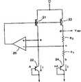
图6是表示BGR电路内部结构的电路图。FIG. 6 is a circuit diagram showing the internal structure of the BGR circuit.
图7是表示pnp双极晶体管22和24剖面结构的图。FIG. 7 is a diagram showing a cross-sectional structure of the pnp
图8是表示包括代替图8所示BGR电路中的pnp双极晶体管的二极管的BGR电路实例的电路图。FIG. 8 is a circuit diagram showing an example of a BGR circuit including a diode instead of a pnp bipolar transistor in the BGR circuit shown in FIG. 8 .
图9是表示在SOI衬底3上形成二极管情况中剖面结构实例的剖视图。FIG. 9 is a cross-sectional view showing an example of a cross-sectional structure in the case where a diode is formed on an
图10是表示在使用包括n型支撑衬底20的SOI衬底3来形成npn双极晶体管的情况中剖面结构实例的剖视图。10 is a cross-sectional view showing an example of a cross-sectional structure in the case of forming an npn bipolar transistor using an
图11是表示可以通用于所有上述电路阱扩散区的电压施加方法的图。Fig. 11 is a diagram showing a voltage application method that can be commonly used in all the above-mentioned circuit well diffusion regions.
具体实施方式Detailed ways
下文中,将参照附图说明本发明的实施方案。Hereinafter, embodiments of the present invention will be described with reference to the drawings.
(第一实施方案)(first embodiment)
图1是根据本发明第一实施方案的半导体集成器件的剖视图。在图1的半导体集成器件中,表示了使用FBCs作为存储元件的半导体存储器件的外围电路的剖面结构。1 is a cross-sectional view of a semiconductor integrated device according to a first embodiment of the present invention. In the semiconductor integrated device of FIG. 1, a cross-sectional structure of a peripheral circuit of a semiconductor memory device using FBCs as a memory element is shown.
在本实施方案中,使用包括p型支撑衬底1和作为薄膜形成的埋入式氧化物膜2的SOI衬底3。通过形成埋入式氧化物膜2作为薄膜,可以充分地保证FBCs的信号数量,并且可以延长数据保留时间。In the present embodiment,
图1中,在SOI衬底3中的埋入式氧化物膜2的上表面上形成FBC 4、NFET 5和PFET 6,使它们彼此分开。在FBC 4下方的p型支撑衬底1中形成n阱扩散区7,与埋入式氧化物膜2接触。在NFET5下方的p型支撑衬底1中形成p阱扩散区8。在PFET 6下方的p型支撑衬底1中形成n阱扩散区9。In FIG. 1,
设置p型支撑衬底1至电压Vsub=0V。向n阱扩散区7施加电压VPL=1V。设置p阱扩散区8至电压VPL=0V。向n阱扩散区9施加电压VPL=2.5V。Set the p-
与p型支撑衬底1相比,只需要将n阱扩散区7反向偏置。因此,不总是需要设置n阱扩散区7等于1V,但是可以施加0至1V范围内的电压。Compared with the p-
p阱扩散区8中的电压VPL不总是需要为0V,而只需要为0V或更低。按照相同的方式,n阱扩散区9中的电压VPL不总是需要为2.5V,而只需要为至少Vcc。Voltage VPL in p-
通过这样分别对p阱扩散区8和n阱扩散区9施加预定的电压,对于NFET 5和PFET 6不形成反向沟道(back channel),并且改善了器件的特性。举例来说,如果NFET 5下方埋入式氧化物膜2的下表面侧具有高于0V的电位,担心沿着NFET 5沟道区下方埋入式氧化物膜2可能形成反向沟道。但是,在本实施方案中,在埋入式氧化物膜2的下表面侧上面提供了p阱扩散区8,并且设置p阱扩散区8为0V或者低于0V的电压。因此,不用担心对于NFET 5会形成反向沟道,并且可以改善NFET的器件特性。By thus applying predetermined voltages to the p-
按照相同的方式,如果PFET 6下方埋入式氧化物膜2的下表面侧具有低于2.5V的电位,担心沿着PFET 6沟道区下方埋入式氧化物膜可能形成反向沟道。但是,在本实施方案中,在埋入式氧化物膜2的下表面侧上面提供了n阱扩散区9,并且设置n阱扩散区9为至少2.5V的电压。因此,不用担心对于PFET 6会形成反向沟道,并且可以改善PFET的器件特性。In the same manner, if the lower surface side of the buried
图2是表示图1的改进实施例的图。图2表示向p型支撑衬底1施加电压VSUB=-1V,并且就在FBC 4下方形成p阱扩散区10的实施例。向p阱扩散区10施加与对p型支撑衬底1相同的电压VPL=-1V。还对就位于NFET 5下方的p阱扩散区8施加与对p型支撑衬底1相同的电压VPL=-1V。如果p阱扩散区8中的电压VPL为0V或更低,在NFET 5中不会形成反向沟道。在图2的情况中,可以防止发生反向沟道。Fig. 2 is a diagram showing a modified example of Fig. 1 . FIG. 2 shows an embodiment in which a voltage VSUB=-1V is applied to a p-
因此,在第一实施方案中,根据NFET 5和PFET 6的形成位置,在埋入式氧化物膜的下表面侧上形成p阱扩散区8和n阱扩散区9,并且分别向阱扩散区中施加预定的电压。因此,在NFET 5和PFET 6中不会形成反向沟道,并且提高了器件特性。Therefore, in the first embodiment, the p-
(第二实施方案)(second embodiment)
在第二实施方案中,当向SOI衬底3的p型支撑衬底1施加低于0V的电压时,阻止形成反向沟道。In the second embodiment, when a voltage lower than 0 V is applied to the p-
图3是根据本发明第二实施方案的半导体集成器件的剖视图。按照与图1相同的方式,图3所示的半导体集成器件包括在包括p型支撑衬底1和作为薄膜形成的埋入式氧化物膜2的SOI衬底3上形成的FBC 4、NFET 5和PFET 6,使它们彼此分开。Fig. 3 is a sectional view of a semiconductor integrated device according to a second embodiment of the present invention. In the same manner as in FIG. 1, the semiconductor integrated device shown in FIG. 3 includes
按照与图1相同的方式,在位于FBC 4下方的p型支撑衬底1中形成n阱扩散区7。在位于NFET 5下方的p型支撑衬底1中形成p阱扩散区8。此外,形成n阱扩散区11,使之与p阱扩散区8相邻。在n阱扩散区9和11下表面下方形成n阱扩散区12。结果,p阱扩散区8与p型支撑衬底1分开。In the same manner as in FIG. 1, an n-well diffusion region 7 is formed in the p-
向n阱扩散区7施加电压VPL=1V。设置p阱扩散区8至电压VPL=0V。向n阱扩散区9施加电压VPL=2.5V。因此,通过提供n阱扩散区12可以向p阱扩散区8施加与p型支撑衬底1不同的电压。A voltage VPL=1V is applied to the n-well diffusion region 7 . Set the p-
结果,按照与第一实施方案相同的方式,在NFET 5和PFET 6中都不会形成反向沟道。As a result, in the same manner as in the first embodiment, no reverse channel is formed in either the
图4是表示图3的改进实施例的图。图4表示就在FBC 4下方形成p阱扩散区10,并且向所述p阱扩散区10施加电压VPL=-1V的实施例。除了p阱扩散区10外,图4与图3相同。按照与图3相同的方式,通过n阱扩散区12,p阱扩散区8与p型支撑衬底1分开。FIG. 4 is a diagram showing a modified example of FIG. 3 . FIG. 4 shows an embodiment in which a p-
在第二实施方案中,除了在区8和9下方提供n阱扩散区12,使p阱扩散区与p型支撑衬底1分开外,就在NFET 5和PFET 6的下方分别形成p阱扩散区8和n阱扩散区9。因此,即使向p型支撑衬底1施加负电压,为了防止在NFET 5和PFET 6中形成反向沟道,可以向p阱扩散区8n阱扩散区9施加必需和足够的电压。In the second embodiment, in addition to providing the n-
(第三实施方案)(third embodiment)
在第一和第二实施方案中,使用包括p型支撑衬底1的SOI衬底3。但是,可以使用包括n型支撑衬底的SOI衬底3。In the first and second embodiments,
在此情况下,与图1相应的结构变成如图5所示。图5所示的半导体集成器件包括在FBC 4下方形成的n阱扩散区、在NFET 5下方形成的p阱扩散区8、在PFET 6下方形成的n阱扩散区9,以及在p阱扩散区8和n阱扩散区9的下表面侧上形成的p阱扩散区13。In this case, the structure corresponding to FIG. 1 becomes as shown in FIG. 5 . The semiconductor integrated device shown in Fig. 5 comprises the n-well diffusion region formed below the
设置n型支撑衬底20至电压Vsub=0V。向n阱扩散区7施加电压VPL=0V。设置p阱扩散区8至电压VPL=0V。向n阱扩散区9施加电压VPL=2.5V。提供p阱扩散区13来防止n阱扩散区9和n型支撑衬底20之间的短路。The n-
在图5所示的半导体集成器件中,在NFET 5和PFET 6中都不会形成反向沟道。In the semiconductor integrated device shown in FIG. 5, a reverse channel is not formed in both the
因此,还在包括n型支撑衬底20的SOI衬底3的情况中,按照与p型支撑衬底1中相同的方式,通过分别在NFET 5和PFET 6下方形成p阱扩散区8和n阱扩散区9,并且分别向所述区域施加预定的电压,可以保证不会形成反向沟道。Therefore, also in the case of the
(第四实施方案)(fourth embodiment)
在第四实施方案中,通过使用包括作为薄膜形成的埋入式氧化物膜的SOI衬底3,形成带隙参考电路(BGR电路)。In the fourth embodiment, by using the
综上所述,在许多情况中,在FBC4存储器的外围电路中提供参考电位产生电路,其总是能够产生固定的参考电压,而不受电源电压变化、温度变化和器件特性变化的影响。To sum up, in many cases, a reference potential generating circuit is provided in the peripheral circuit of the FBC4 memory, which can always generate a fixed reference voltage regardless of power supply voltage variation, temperature variation, and device characteristic variation.
图6是表示作为参考电位产生电路一个实例的BGR电路内部结构的电路图。图6所示的BGR电路包括在电源电压和接地电压之间串联的PFET 21和pnp晶体管22、按相同方式在电源电压和接地电压之间串联的PFET 23、电阻R1、电阻R2和pnp晶体管24,以及基于电阻R1和R2之间的电压和pnp晶体管22的发射极电压的电位差,向PFET 21和23的栅极供应电压的运算放大器25。参考电压VREF是PFET 23在其漏极的输出。FIG. 6 is a circuit diagram showing an internal structure of a BGR circuit as an example of a reference potential generating circuit. The BGR circuit shown in Fig. 6 comprises a
晶体管22是具有面积A的pnp双极晶体管,而通过并联连接每个具有相等面积A的pnp双极晶体管来形成晶体管24。
分别流过晶体管22和24的电流分别由等式(1)和(2)来表示。The currents flowing through
I=Is×exp[Va/VT](1)I=Is×exp[Va/VT](1)
I=n×Is×exp[Vb/VT](2)I=n×Is×exp[Vb/VT](2)
此处,Is是具有面积A的晶体管22的饱和电流。Va是PFET 21的漏极电压。Vb是pnp双极晶体管的发射极电压。VT是热电压kT/q。此外,k是玻耳兹曼常数(1.38×10-23J/K)。T是绝对温度,并且q是基本电荷(1.6×10-19C)。Here, Is is the saturation current of the
运算放大器25放大电位差(Va-Vb)。电位差(Va-Vb)由等式(3)表示。The
Va-Vb=VT×ln[I/Is]-VT×ln[I/(n×Is)]=VT×ln[n](3)Va-Vb=VT×ln[I/Is]-VT×ln[I/(n×Is)]=VT×ln[n] (3)
在图6所示的电路中,通过反馈回路精确控制,使之满足关系Va=Vc。因此,等式(4)成立。In the circuit shown in FIG. 6, the feedback loop is precisely controlled to satisfy the relationship Va=Vc. Therefore, equation (4) holds.
Vc-Vb=Va-Vb=VT×ln[n](4)Vc-Vb=Va-Vb=VT×ln[n] (4)
此外,等式(5)也成立。In addition, equation (5) also holds.
Vd-Vb=(1+R2/R1)×(Vc-Vb)=(1+R2/R1)×VT×ln [n](5)Vd-Vb=(1+R2/R1)×(Vc-Vb)=(1+R2/R1)×VT×ln [n](5)
从等式(4)和(5),得到等式(6)。From equations (4) and (5), equation (6) is obtained.
VREF=VBE+Vd-Vb=VBE+(1+R2/R1)×VT×ln[n](6)VREF=VBE+Vd-Vb=VBE+(1+R2/R1)×VT×ln[n](6)
此处,VBE是具有面积n×A的pnp双极晶体管24的基极-发射极电压。等式(6)对温度的导数由等式(7)表示。Here, VBE is the base-emitter voltage of the pnp
现在假设VBE具有负的导数-α,其中α=1.5mV/K(@室温)。因此为了消除室温下VREF对温度的依赖关系,需要满足等式(8)。Now assume that VBE has a negative derivative -α, where α=1.5mV/K(@room temperature). Therefore, in order to eliminate the temperature dependence of VREF at room temperature, equation (8) needs to be satisfied.
(1+R2/R1)×ln[n]=α×(k/q)=17.4(8)(1+R2/R1)×ln[n]=α×(k/q)=17.4(8)
根据等式(8),举例来说通过设置,使之满足关系R2/R1=4并且n=32.5,可以消除在室温下VREF对温度的依赖关系。According to Equation (8), for example, by setting to satisfy the relationship R2/R1 = 4 and n = 32.5, the temperature dependence of VREF at room temperature can be eliminated.
因此,通过适当选择电阻R1和R2之间的比例和晶体管22和24之间的比例,可以获得与温度和电源电压无关的稳定的参考电压。即使工艺变化,所述稳定条件只取决于器件参数的比例,因此可以获得固定的参考电压。Therefore, by properly selecting the ratio between resistors R1 and R2 and the ratio between
图7是表示pnp双极晶体管22和24剖面结构的图。通过使用包括作为薄膜形成的埋入式氧化物膜2的SOI衬底3来形成图7所示的晶体管。在埋入式氧化物膜2的上表面上,连续形成硅膜28和绝缘膜29。FIG. 7 is a diagram showing a cross-sectional structure of the pnp
沿着埋入式氧化物膜2的下表面,在p型支撑衬底1中形成用于集电极的n阱扩散区31和p+扩散区32。在n阱扩散区31内部,沿着埋入式氧化物膜2进一步形成用于基极的n+扩散区33和用于发射极的p+扩散区34。Along the lower surface of buried
分别在p+扩散区32、n+扩散区33和p+扩散区34中形成穿过埋入式氧化物膜2的接触35、36和37。分别在接触35、36和37中形成集电极38、基极39和发射极40。Contacts 35 , 36 and 37 are formed through buried
在图7所示的pnp双极晶体管中,作为薄膜形成埋入式氧化物膜2。因此,可以容易地从阱扩散区向上形成接触。In the pnp bipolar transistor shown in FIG. 7, the buried
按照与FBC 4相同的方式,可以在SOI衬底3上面形成图7所示的pnp双极晶体管及其在图1中所示的外围电路。结果,可以容易地在相同的衬底上形成FBC 4及其外围电路使用的参考电压产生电路。In the same manner as the
但是,在向图3所示的支撑衬底施加负电压的情况下,不能形成pnp双极晶体管。原因是如果支撑衬底具有负电位,不能制造等于接地电位的pnp双极晶体管的集电极。因此在此情况下,可以使用二极管来代替pnp双极晶体管。However, in the case where a negative voltage is applied to the support substrate shown in FIG. 3, a pnp bipolar transistor cannot be formed. The reason is that the collector of a pnp bipolar transistor equal to ground potential cannot be fabricated if the supporting substrate has a negative potential. So in this case a diode can be used instead of a pnp bipolar transistor.
图8是表示包括代替pnp双极晶体管的二极管的BGR电路一个实例的电路图。在图8所示的BGR电路中,用二极管41和42代替图6中所示的pnp双极晶体管22和24。二极管41的阳极与PFET 21的漏极连接,并且二极管41的阴极接地。二极管42的阳极与电阻R1连接,并且二极管42的阴极接地。FIG. 8 is a circuit diagram showing an example of a BGR circuit including a diode instead of a pnp bipolar transistor. In the BGR circuit shown in FIG. 8,
图9是表示在于SOI衬底3上形成二极管的情况中剖面结构一个实例的剖视图。在埋入式氧化物膜2下表面侧上面的p型支撑衬底1中,形成n阱扩散区45用于电源、p+扩散区46用于阳极、n+扩散区47用于阴极,以及n阱扩散区48用于电源。在n阱扩散区45和n阱扩散区48中,分别形成n+扩散区49和50。FIG. 9 is a cross-sectional view showing an example of a cross-sectional structure in the case of forming a diode on an
分别在n+扩散区49、p+扩散区46、n+扩散区47和n+扩散区50中形成穿过埋入式氧化物膜2的接触51、52、53和54。接触51和54分别与电源端相连。接触52与阳极57相连,并且接触53与阴极58相连。
形成n阱扩散区45和48,使之比p+扩散区46和n+扩散区47更深。在n阱扩散区45和48的下表面下方形成n阱扩散区59。通过n阱扩散区59,p+扩散区46与p型支撑衬底1分开。N well
具有图9所示结构的二极管可以设置p型支撑衬底1至负电位。因此,可以在与具有图3所示结构的半导体集成器件的相同衬底上形成二极管。A diode having the structure shown in FIG. 9 can set the p-
因此,在第四实施方案中,通过使用包括作为薄膜形成的埋入式氧化物膜的SOI衬底3来形成双极晶体管和二极管。因此,可以容易地在相同的衬底上形成FBC 4存储器及其外围电路所需的产生参考电压的参考电压产生电路。Therefore, in the fourth embodiment, bipolar transistors and diodes are formed by using the
(其它实施方案)(other implementations)
已经参照图7说明了形成了pnp双极晶体管的实施例。但是,还可以形成npn双极晶体管。图10是表示在通过使用包括n型支撑衬底20的SOI衬底3形成npn双极晶体管的情况中的剖面结构的剖视图。An embodiment in which a pnp bipolar transistor is formed has been described with reference to FIG. 7 . However, npn bipolar transistors can also be formed. 10 is a cross-sectional view showing a cross-sectional structure in a case where an npn bipolar transistor is formed by using an
图10中所示的npn双极晶体管包括在埋入式氧化物膜2下表面侧上形成的n+扩散区61和p阱扩散区62。在p阱扩散区62内,形成用于基极的p+扩散区63和用于发射极的n+扩散区64。按照与图7相同的方式,分别在n+扩散区61、p+扩散区63和n+扩散区64中形成穿过埋入式氧化物膜2的接触65、66和67。接触65、66和67分别与集电极68、基极69和发射极70连接。The npn bipolar transistor shown in FIG. 10 includes n+ diffusion region 61 and p
图10中所示的npn双极晶体管可以在与例如图5所示的半导体集成器件的相同衬底上形成。The npn bipolar transistor shown in FIG. 10 can be formed on the same substrate as the semiconductor integrated device shown in FIG. 5, for example.
通过形成穿过埋入式氧化物膜2的接触并且在所述接触的上表面侧形成电极,可以向上述FBC 4的阱扩散区、FBC 4的外围电路,以及双极晶体管和二极管上施加电压。By forming a contact through the buried
图11是表示可以通用于所有上述电路阱扩散区的电压施加方法的图。如图11所示,在p型支撑衬底1中形成n阱扩散区41,从而与埋入式氧化物膜2接触。在于n阱扩散区41内部形成n+扩散区42的情况中,应该形成从n+扩散区42向上穿过埋入式氧化物膜2的接触43。所述接触与电极44连接。按照相同的方式,还应该在p型支撑衬底1中的p+扩散区45的上方形成穿过埋入式氧化物膜2的接触46,并且所述接触46可以与电极47连接。Fig. 11 is a diagram showing a voltage application method that can be commonly used in all the above-mentioned circuit well diffusion regions. As shown in FIG. 11 , n-
Claims (14)
Translated fromChineseApplications Claiming Priority (2)
| Application Number | Priority Date | Filing Date | Title |
|---|---|---|---|
| JP2004252757AJP2006073627A (en) | 2004-08-31 | 2004-08-31 | Semiconductor integrated device |
| JP2004252757 | 2004-08-31 |
Publications (2)
| Publication Number | Publication Date |
|---|---|
| CN1744321A CN1744321A (en) | 2006-03-08 |
| CN100405603Ctrue CN100405603C (en) | 2008-07-23 |
Family
ID=35943850
Family Applications (1)
| Application Number | Title | Priority Date | Filing Date |
|---|---|---|---|
| CNB2005100966855AExpired - Fee RelatedCN100405603C (en) | 2004-08-31 | 2005-08-31 | Semiconductor integrated device |
Country Status (3)
| Country | Link |
|---|---|
| US (1) | US7244991B2 (en) |
| JP (1) | JP2006073627A (en) |
| CN (1) | CN100405603C (en) |
Families Citing this family (29)
| Publication number | Priority date | Publication date | Assignee | Title |
|---|---|---|---|---|
| JP2007242950A (en)* | 2006-03-09 | 2007-09-20 | Toshiba Corp | Semiconductor memory device |
| US7851859B2 (en)* | 2006-11-01 | 2010-12-14 | Samsung Electronics Co., Ltd. | Single transistor memory device having source and drain insulating regions and method of fabricating the same |
| US8547756B2 (en) | 2010-10-04 | 2013-10-01 | Zeno Semiconductor, Inc. | Semiconductor memory device having an electrically floating body transistor |
| KR100801707B1 (en)* | 2006-12-13 | 2008-02-11 | 삼성전자주식회사 | Floating Body Memory and Manufacturing Method Thereof |
| KR100881825B1 (en)* | 2007-07-27 | 2009-02-03 | 주식회사 하이닉스반도체 | Semiconductor device and manufacturing method thereof |
| US8174886B2 (en) | 2007-11-29 | 2012-05-08 | Zeno Semiconductor, Inc. | Semiconductor memory having electrically floating body transistor |
| US8264875B2 (en) | 2010-10-04 | 2012-09-11 | Zeno Semiconducor, Inc. | Semiconductor memory device having an electrically floating body transistor |
| US8130547B2 (en) | 2007-11-29 | 2012-03-06 | Zeno Semiconductor, Inc. | Method of maintaining the state of semiconductor memory having electrically floating body transistor |
| CN101937091B (en)* | 2007-12-12 | 2012-07-25 | 中国科学院微电子研究所 | Stacking measuring circuit with adjustable measuring range |
| CN101458337B (en)* | 2007-12-12 | 2010-12-08 | 中国科学院微电子研究所 | Dual-probe PMOS radiation dosimeter based on silicon-on-insulator |
| US8014200B2 (en) | 2008-04-08 | 2011-09-06 | Zeno Semiconductor, Inc. | Semiconductor memory having volatile and multi-bit, non-volatile functionality and methods of operating |
| KR20100062213A (en)* | 2008-12-01 | 2010-06-10 | 삼성전자주식회사 | Semiconductor device and manufacturing method of semiconductor device |
| US8018007B2 (en) | 2009-07-20 | 2011-09-13 | International Business Machines Corporation | Selective floating body SRAM cell |
| FR2955204B1 (en)* | 2010-01-14 | 2012-07-20 | Soitec Silicon On Insulator | DRAM MEMORY CELL HAVING A VERTICAL BIPOLAR INJECTOR |
| US10340276B2 (en) | 2010-03-02 | 2019-07-02 | Zeno Semiconductor, Inc. | Method of maintaining the state of semiconductor memory having electrically floating body transistor |
| JP5605028B2 (en)* | 2010-07-05 | 2014-10-15 | 株式会社デンソー | Semiconductor device |
| US8835900B2 (en) | 2011-06-07 | 2014-09-16 | International Business Machines Corporation | Highly scaled ETSOI floating body memory and memory circuit |
| US20120313173A1 (en)* | 2011-06-07 | 2012-12-13 | Rf Micro Devices, Inc. | Method for isolating rf functional blocks on silicon-on-insulator (soi) substrates |
| FR2980035B1 (en)* | 2011-09-08 | 2013-10-04 | Commissariat Energie Atomique | INTEGRATED CIRCUIT IN SELF COMPRISING ADJACENT CELLS OF DIFFERENT TYPES |
| US8809905B2 (en)* | 2011-12-28 | 2014-08-19 | Taiwan Semiconductor Manufacturing Company, Ltd. | Vertical BJT and SCR for ESD |
| US9208880B2 (en) | 2013-01-14 | 2015-12-08 | Zeno Semiconductor, Inc. | Content addressable memory device having electrically floating body transistor |
| US9214932B2 (en) | 2013-02-11 | 2015-12-15 | Triquint Semiconductor, Inc. | Body-biased switching device |
| US9203396B1 (en) | 2013-02-22 | 2015-12-01 | Triquint Semiconductor, Inc. | Radio frequency switch device with source-follower |
| US8865561B2 (en) | 2013-03-14 | 2014-10-21 | International Business Machines Corporation | Back-gated substrate and semiconductor device, and related method of fabrication |
| US9379698B2 (en) | 2014-02-04 | 2016-06-28 | Triquint Semiconductor, Inc. | Field effect transistor switching circuit |
| US9318492B2 (en) | 2014-04-02 | 2016-04-19 | International Business Machines Corporation | Floating body storage device employing a charge storage trench |
| JP2021009961A (en)* | 2019-07-02 | 2021-01-28 | 株式会社東海理化電機製作所 | Semiconductor integrated circuit |
| WO2021002276A1 (en)* | 2019-07-02 | 2021-01-07 | 株式会社東海理化電機製作所 | Semiconductor integrated circuit |
| JP2021009962A (en)* | 2019-07-02 | 2021-01-28 | 株式会社東海理化電機製作所 | Semiconductor integrated circuit |
Citations (3)
| Publication number | Priority date | Publication date | Assignee | Title |
|---|---|---|---|---|
| US20030155615A1 (en)* | 2002-02-21 | 2003-08-21 | Yoshifumi Yoshida | Structure of a semiconductor integrated circuit and method of manufacturing the same |
| JP2003282878A (en)* | 2002-03-20 | 2003-10-03 | Citizen Watch Co Ltd | Semiconductor device and its fabricating method |
| CN1450650A (en)* | 2002-03-25 | 2003-10-22 | 精工电子有限公司 | Semiconductor device and mfg method thereof |
Family Cites Families (7)
| Publication number | Priority date | Publication date | Assignee | Title |
|---|---|---|---|---|
| JPH06151859A (en)* | 1992-09-15 | 1994-05-31 | Canon Inc | Semiconductor device |
| JP2001036054A (en)* | 1999-07-19 | 2001-02-09 | Mitsubishi Electric Corp | Method for manufacturing SOI substrate |
| US6365932B1 (en)* | 1999-08-20 | 2002-04-02 | Denso Corporation | Power MOS transistor |
| JP4216483B2 (en)* | 2001-02-15 | 2009-01-28 | 株式会社東芝 | Semiconductor memory device |
| JP2002299591A (en)* | 2001-03-30 | 2002-10-11 | Toshiba Corp | Semiconductor device |
| JP4282388B2 (en)* | 2003-06-30 | 2009-06-17 | 株式会社東芝 | Semiconductor memory device |
| JP3933608B2 (en)* | 2003-06-30 | 2007-06-20 | 株式会社東芝 | Semiconductor memory device and semiconductor integrated circuit |
- 2004
- 2004-08-31JPJP2004252757Apatent/JP2006073627A/enactivePending
- 2005
- 2005-03-30USUS11/092,920patent/US7244991B2/ennot_activeExpired - Fee Related
- 2005-08-31CNCNB2005100966855Apatent/CN100405603C/ennot_activeExpired - Fee Related
Patent Citations (3)
| Publication number | Priority date | Publication date | Assignee | Title |
|---|---|---|---|---|
| US20030155615A1 (en)* | 2002-02-21 | 2003-08-21 | Yoshifumi Yoshida | Structure of a semiconductor integrated circuit and method of manufacturing the same |
| JP2003282878A (en)* | 2002-03-20 | 2003-10-03 | Citizen Watch Co Ltd | Semiconductor device and its fabricating method |
| CN1450650A (en)* | 2002-03-25 | 2003-10-22 | 精工电子有限公司 | Semiconductor device and mfg method thereof |
Also Published As
| Publication number | Publication date |
|---|---|
| CN1744321A (en) | 2006-03-08 |
| US20060046408A1 (en) | 2006-03-02 |
| US7244991B2 (en) | 2007-07-17 |
| JP2006073627A (en) | 2006-03-16 |
Similar Documents
| Publication | Publication Date | Title |
|---|---|---|
| CN100405603C (en) | Semiconductor integrated device | |
| US6310799B2 (en) | Negative resistance device | |
| US7256643B2 (en) | Device and method for generating a low-voltage reference | |
| Itoh et al. | Ultra-low voltage nano-scale memories | |
| TW200945345A (en) | Semiconductor memory device | |
| JPH0671067B2 (en) | Semiconductor device | |
| JP2004335031A (en) | Semiconductor storage device | |
| JP2005026353A (en) | Semiconductor memory device and semiconductor integrated circuit | |
| JPH11220109A (en) | Integrated circuit memory device having independently biased subwell regions and method of manufacturing the same | |
| KR100712089B1 (en) | Semiconductor memory device and manufacturing method | |
| JP5078118B2 (en) | Semiconductor memory device | |
| US5942784A (en) | Semiconductor device | |
| JPH0821680B2 (en) | Integrated circuit | |
| US5686752A (en) | Semiconductor device having a CMOS element as a buffer | |
| US7733718B2 (en) | One-transistor type DRAM | |
| US11029216B1 (en) | IC with stragically biased digital circuitry | |
| CN113963738B (en) | Antifuse device and method for programming antifuse cell | |
| KR20030021124A (en) | Semiconductor device and manufacturing method thereof | |
| US4791611A (en) | VLSI dynamic memory | |
| JPH10163429A (en) | Semiconductor device | |
| KR0135712B1 (en) | Semiconductor integrated circuit | |
| JP2974024B2 (en) | MOS memory point | |
| US6172554B1 (en) | Power supply insensitive substrate bias voltage detector circuit | |
| JP3670139B2 (en) | Semiconductor memory device | |
| JP2008109148A (en) | Semiconductor integrated device |
Legal Events
| Date | Code | Title | Description |
|---|---|---|---|
| C06 | Publication | ||
| PB01 | Publication | ||
| C10 | Entry into substantive examination | ||
| SE01 | Entry into force of request for substantive examination | ||
| C14 | Grant of patent or utility model | ||
| GR01 | Patent grant | ||
| C17 | Cessation of patent right | ||
| CF01 | Termination of patent right due to non-payment of annual fee | Granted publication date:20080723 |