CN100405165C - Backlight system and its reflector - Google Patents
Backlight system and its reflectorDownload PDFInfo
- Publication number
- CN100405165C CN100405165CCNB2005100371290ACN200510037129ACN100405165CCN 100405165 CCN100405165 CCN 100405165CCN B2005100371290 ACNB2005100371290 ACN B2005100371290ACN 200510037129 ACN200510037129 ACN 200510037129ACN 100405165 CCN100405165 CCN 100405165C
- Authority
- CN
- China
- Prior art keywords
- light
- backlight system
- incident surface
- reflective
- indicates
- Prior art date
- Legal status (The legal status is an assumption and is not a legal conclusion. Google has not performed a legal analysis and makes no representation as to the accuracy of the status listed.)
- Expired - Fee Related
Links
Images


Classifications
- G—PHYSICS
- G02—OPTICS
- G02B—OPTICAL ELEMENTS, SYSTEMS OR APPARATUS
- G02B6/00—Light guides; Structural details of arrangements comprising light guides and other optical elements, e.g. couplings
- G02B6/0001—Light guides; Structural details of arrangements comprising light guides and other optical elements, e.g. couplings specially adapted for lighting devices or systems
- G02B6/0011—Light guides; Structural details of arrangements comprising light guides and other optical elements, e.g. couplings specially adapted for lighting devices or systems the light guides being planar or of plate-like form
- G02B6/0013—Means for improving the coupling-in of light from the light source into the light guide
- G02B6/0023—Means for improving the coupling-in of light from the light source into the light guide provided by one optical element, or plurality thereof, placed between the light guide and the light source, or around the light source
- G02B6/0031—Reflecting element, sheet or layer
- G—PHYSICS
- G02—OPTICS
- G02B—OPTICAL ELEMENTS, SYSTEMS OR APPARATUS
- G02B6/00—Light guides; Structural details of arrangements comprising light guides and other optical elements, e.g. couplings
- G02B6/0001—Light guides; Structural details of arrangements comprising light guides and other optical elements, e.g. couplings specially adapted for lighting devices or systems
- G02B6/0011—Light guides; Structural details of arrangements comprising light guides and other optical elements, e.g. couplings specially adapted for lighting devices or systems the light guides being planar or of plate-like form
- G02B6/0013—Means for improving the coupling-in of light from the light source into the light guide
- G02B6/0015—Means for improving the coupling-in of light from the light source into the light guide provided on the surface of the light guide or in the bulk of it
- G02B6/0016—Grooves, prisms, gratings, scattering particles or rough surfaces
- G—PHYSICS
- G02—OPTICS
- G02B—OPTICAL ELEMENTS, SYSTEMS OR APPARATUS
- G02B6/00—Light guides; Structural details of arrangements comprising light guides and other optical elements, e.g. couplings
- G02B6/0001—Light guides; Structural details of arrangements comprising light guides and other optical elements, e.g. couplings specially adapted for lighting devices or systems
- G02B6/0011—Light guides; Structural details of arrangements comprising light guides and other optical elements, e.g. couplings specially adapted for lighting devices or systems the light guides being planar or of plate-like form
- G02B6/0033—Means for improving the coupling-out of light from the light guide
- G02B6/0035—Means for improving the coupling-out of light from the light guide provided on the surface of the light guide or in the bulk of it
- G02B6/0038—Linear indentations or grooves, e.g. arc-shaped grooves or meandering grooves, extending over the full length or width of the light guide
Landscapes
- Physics & Mathematics (AREA)
- General Physics & Mathematics (AREA)
- Optics & Photonics (AREA)
- Planar Illumination Modules (AREA)
- Liquid Crystal (AREA)
Abstract
Translated fromChinese
Description
Translated fromChinese【技术领域】【Technical field】
本发明涉及一种背光系统和用于该背光系统的反光罩,特别是关于一种用于给液晶显示器面板提供照明的背光系统。The invention relates to a backlight system and a reflector used for the backlight system, in particular to a backlight system for providing illumination to a liquid crystal display panel.
【背景技术】【Background technique】
由于液晶显示器面板中的液晶本身不具有发光特性,因而,为达到显示效果,需要给液晶显示器面板提供一面光源装置,如背光系统,其功能在于向液晶显示器面板提供亮度充分而且分布均匀的面光源。Since the liquid crystal in the liquid crystal display panel itself does not have light-emitting characteristics, in order to achieve the display effect, it is necessary to provide a surface light source device for the liquid crystal display panel, such as a backlight system, whose function is to provide a surface light source with sufficient brightness and uniform distribution to the liquid crystal display panel .
请参阅图1,一种现有技术的背光系统10主要由两个点状光源11、导光板12、反射片13、扩散片14和两个棱镜片15组成。该点状光源11为发光二极管(Light Emitting Diode,LED)。该导光板12包括入光面121、出光面122和底面123。该点状光源11设置于该导光板12的入光面121一侧,该两个棱镜片15、扩散片14、导光板12和反射片13依次层叠设置。该点状光源11发出的光线经入光面121进入该导光板12,该导光板12导引光线从出光面122出射。反射片13将由导光板12的底面123出射的光线再次反射入该导光板12内,提高光线的利用率。扩散片14的作用为将入射到其内的光线散射而使显示面板的图案柔和化。棱镜片15也称集光片,其作用是对光线产生汇聚作用,使光线的方向尽可能的朝垂直于导光板12出光面122的方向出射,以提高背光系统10的出光亮度。Referring to FIG. 1 , a prior
再请参照图2,作为点状光源11的发光二极管具有一定的发光角度。正对点状光源11的部分入光面121接收的光线L1与该入光面121垂直,该光线L1射入导光板12内后继续传播,并由正对点状光源11的部分出光面122出射。对应两个点状光源11之间的部分入光面121接收的光线L2与该入光面121成一定锐角,该光线L2在对应入光面121处的分布较少,从而使得对应两个点状光源11之间的部分入光面121的部分出光面122形成一光线亮度较低的暗区124(图中虚线所围区域),该暗区124的存在影响整个背光系统10的出光均匀性。Referring to FIG. 2 again, the light emitting diode as the
【发明内容】【Content of invention】
以下,将以实施例说明一种背光系统,以及一种用于该背光系统的反光罩。Hereinafter, a backlight system and a reflector used in the backlight system will be described with an embodiment.
为实现上述内容,提供一种背光系统,其包括多个光源、一反光罩和一导光板。该导光板包括入光面、连接于该入光面的出光面和相对于该出光面的底面,该光源相对该入光面设置。该反光罩具有多个反射单元,该多个反射单元分别收容该多个光源,各反射单元具有两个相对设置的反射面。该两个反射面与该入光面相对且该两个反射面的截面形状在一极坐标中由如下方程限定:


以及,提供一种反光罩,该反光罩具有两个相对设置的反射面,该两个反射面的截面形状在一极坐标中由如下方程限定:

与现有技术相比,因本实施例的背光系统采用反光罩的反射面的截面形状由特定方程限定,该形状的反射面可以实现对导光板入光面的均匀照明,从而使得该背光系统的发光亮度的均匀性大大提高。Compared with the prior art, because the backlight system of this embodiment uses the cross-sectional shape of the reflective surface of the reflector to be limited by a specific equation, the reflective surface of this shape can realize uniform illumination on the light-incident surface of the light guide plate, so that the backlight system The uniformity of the luminous brightness is greatly improved.
【附图说明】【Description of drawings】
图1是一种现有技术的背光系统的立体分解示意图。FIG. 1 is a three-dimensional exploded schematic diagram of a backlight system in the prior art.
图2是图1所示背光系统的光路示意图。FIG. 2 is a schematic diagram of an optical path of the backlight system shown in FIG. 1 .
图3是本发明第一实施例的背光系统的立体分解示意图。FIG. 3 is an exploded perspective view of the backlight system according to the first embodiment of the present invention.
图4是该第一实施例的背光系统中的反光罩的反射面沿图3中IV-IV方向的截面示意图。FIG. 4 is a schematic cross-sectional view of the reflective surface of the reflector in the backlight system of the first embodiment along the direction IV-IV in FIG. 3 .
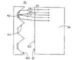
图5是该第一实施例的背光系统的光路示意图。FIG. 5 is a schematic diagram of the optical path of the backlight system of the first embodiment.
图6是图5中VI部分的放大示意图。FIG. 6 is an enlarged schematic view of part VI in FIG. 5 .
图7是本发明第二实施例的背光系统的部分平面示意图。7 is a partial plan view of a backlight system according to a second embodiment of the present invention.
【具体实施方式】【Detailed ways】
下面将结合附图对本发明作进一步的详细说明。The present invention will be further described in detail below in conjunction with the accompanying drawings.
请参阅图3,本发明第一实施例的背光系统30包括一反光罩41、多个光源42、一导光板50、一反射片43和一光学膜片44。该光源42收容在该反光罩41内,且该光源42的发光面421正对该导光板50的入光面51设置。该光学膜片44、导光板50和反射片43依次层叠设置。Please refer to FIG. 3 , the
该反光罩41具有与该光源42数量相同的多个反射单元,各反射单元具有两个相对设置的反射面411、412。该反射面411和412之间形成一收容空间,各光源42即收容在该收容空间的底部。The
一起参照图4,该反光罩41的反射面411、412的截面形状在一极坐标中由一特定方程限定。依照该特定方程限定反射面411、412截面形状的反光罩41可以将光源42发出的光线对入光面51均匀照明,从而提高整个背光系统30发光亮度的均匀性。Referring to FIG. 4 together, the cross-sectional shape of the
下面结合图4,对该反光罩41的反射面411、412的截面形状的设计过程及其相应效果进行说明。The process of designing the cross-sectional shapes of the
在以发光面421下端点为极坐标原点的极坐标中,反光罩41的反射面411、412用ρ,φ极坐标表示,光源42的发光面421位于反射面411、412之间。其中,ρ0表示极坐标中的长度单位,

且有:and have:
在极坐标中,反光罩41的反射面411、412的方程可以写成:In polar coordinates, the equations of the

其中角度γ和θ的范围如下:where the ranges of angles γ and θ are as follows:
根据光强与边缘光线间的距离成正比的边缘光线原理,单位亮度的光源在θ方向的发射光强度为:According to the edge ray principle that the light intensity is proportional to the distance between the edge rays, the emitted light intensity of the light source with unit brightness in the θ direction is:

在

I°(θ)为希望得到的光强分布,对于

根据能量守恒定律,有:According to the law of conservation of energy, there are:

根据方程(1)、(3)和(8),用于产生光强分布I°(θ)的反光罩反射面的截面形状可以被确定。According to equations (1), (3) and (8), the cross-sectional shape of the reflective surface of the reflector used to generate the light intensity distribution I°(θ) can be determined.
背光系统30中需要在入光面51上产生均匀照度,光强分布应该满足:In the

根据(9),可以得到确定反光罩反射面的截面形状的方程如下:According to (9), the equation for determining the cross-sectional shape of the reflective surface of the reflector can be obtained as follows:

再请一起参照图5和图6,该导光板50还包括连接于该入光面51的出光面53和相对于该出光面53的底面52。该导光板50的入光面51设置有多个微结构511,本实施例中,该微结构511为一维菲涅尔透镜,其以正对光源42的对称轴对称分布。该微结构511包括靠近该对称轴的第一平面512和远离该对称轴的第二平面513,该第一平面512垂直于入光面51所在平面514,该第二平面513和平面514形成一锐角α,该锐角α自正对光源42的部位向远离该部位的方向逐渐增大。该导光板50的底面52分布多个散射结构521,本实施例中,该散射结构521为V形凹槽。Referring to FIG. 5 and FIG. 6 together, the
该光源42可为发光二极管。该反射面411和412可以通过镀银或铝等金属膜提高反射率。该光学膜片44可以是扩散片,或者棱镜片,也可以是扩散片与棱镜片的组合。The
光源42发出的一部分光线L5直接投射在该微结构511上,并经该微结构511作用后以垂直于该入光面51所在平面514的方向进入该导光板50,另一部分光线L6投射在反射面411和412后被反射到该微结构511上,并经该微结构511作用后以垂直于入光面51所在平面514的方向进入该导光板50。A part of the light L5 emitted by the
因该背光系统30采用的反光罩41的反射面411、412可以实现对入光面51的均匀照明,配合入光面51的微结构511使光源42发出的光线以垂直于入光面51所在平面514的方向进入该导光板50,经入光面51进入导光板50的光线方向基本相同,且分布较为均匀,从而使得该背光系统30的发光亮度的均匀性大大提高。Because the
请参阅图6,本发明第二实施例的背光系统60同上述的背光系统30基本相同,其主要不同在于:导光板80的入光面81上的微结构811在平行于出光面的方向上的截面为一正弦函数曲线。Please refer to FIG. 6, the
本发明的背光系统还可以有其它实施例,例如:The backlight system of the present invention can also have other embodiments, for example:
本发明背光系统中导光板入光面的微结构为平面或V形凹槽。The microstructure of the light incident surface of the light guide plate in the backlight system of the present invention is a plane or a V-shaped groove.
以直接镀在导光板底面上的反射膜代替反射片。The reflective sheet is replaced by a reflective film directly coated on the bottom surface of the light guide plate.
另外,本领域技术人员还可以在本发明精神内做其它变化,当然,这些依据本发明精神所做的变化,都应包含在本发明所要求保护的范围的内。In addition, those skilled in the art can also make other changes within the spirit of the present invention. Of course, these changes made according to the spirit of the present invention should be included in the scope of protection claimed by the present invention.
Claims (16)
Translated fromChinese


Priority Applications (3)
| Application Number | Priority Date | Filing Date | Title |
|---|---|---|---|
| CNB2005100371290ACN100405165C (en) | 2005-09-05 | 2005-09-05 | Backlight system and its reflector |
| US11/414,598US7123316B1 (en) | 2005-09-05 | 2006-04-28 | Backlight module and reflective cover used therein |
| JP2006240620AJP4426551B2 (en) | 2005-09-05 | 2006-09-05 | Backlight module |
Applications Claiming Priority (1)
| Application Number | Priority Date | Filing Date | Title |
|---|---|---|---|
| CNB2005100371290ACN100405165C (en) | 2005-09-05 | 2005-09-05 | Backlight system and its reflector |
Publications (2)
| Publication Number | Publication Date |
|---|---|
| CN1928653A CN1928653A (en) | 2007-03-14 |
| CN100405165Ctrue CN100405165C (en) | 2008-07-23 |
Family
ID=37085954
Family Applications (1)
| Application Number | Title | Priority Date | Filing Date |
|---|---|---|---|
| CNB2005100371290AExpired - Fee RelatedCN100405165C (en) | 2005-09-05 | 2005-09-05 | Backlight system and its reflector |
Country Status (3)
| Country | Link |
|---|---|
| US (1) | US7123316B1 (en) |
| JP (1) | JP4426551B2 (en) |
| CN (1) | CN100405165C (en) |
Families Citing this family (12)
| Publication number | Priority date | Publication date | Assignee | Title |
|---|---|---|---|---|
| CN100412573C (en)* | 2005-04-15 | 2008-08-20 | 鸿富锦精密工业(深圳)有限公司 | Double-sided light guide plate, surface light source device and display device |
| JP2007041605A (en)* | 2005-08-04 | 2007-02-15 | Boe Hydis Technology Co Ltd | Backlight structure of liquid crystal display device |
| JP2007080544A (en)* | 2005-09-09 | 2007-03-29 | Citizen Electronics Co Ltd | Lighting device |
| TW200933247A (en)* | 2008-01-24 | 2009-08-01 | Nano Prec Corp | Side-type backlight module |
| JP5267298B2 (en) | 2009-04-13 | 2013-08-21 | 株式会社Jvcケンウッド | Backlight device |
| KR101546741B1 (en)* | 2009-05-13 | 2015-08-25 | 삼성디스플레이 주식회사 | Light emitting module and display apparatus having the same |
| CN102374414A (en)* | 2010-08-20 | 2012-03-14 | 奇菱科技股份有限公司 | Illumination device |
| CN104089217A (en)* | 2014-06-20 | 2014-10-08 | 北京京东方视讯科技有限公司 | Backlight source, backlight module and display device |
| CN105759339A (en)* | 2016-02-23 | 2016-07-13 | 安比斯特殊玻璃(苏州)有限公司 | Glass light guide plate and liquid crystal display module thereof |
| CN106292062A (en)* | 2016-08-18 | 2017-01-04 | 武汉华星光电技术有限公司 | Backlight module and there is the liquid crystal display of this backlight module |
| CN109617547A (en)* | 2018-12-30 | 2019-04-12 | 李扬渊 | A kind of panel and key panel with backlight |
| CN111120913B (en)* | 2019-12-31 | 2021-09-10 | 深圳市裕富照明有限公司 | Lighting lamp |
Citations (5)
| Publication number | Priority date | Publication date | Assignee | Title |
|---|---|---|---|---|
| JP2003173713A (en)* | 2001-12-04 | 2003-06-20 | Rohm Co Ltd | Illumination device and liquid crystal display device |
| US6655810B2 (en)* | 2000-06-21 | 2003-12-02 | Fujitsu Display Technologies Corporation | Lighting unit |
| CN1549028A (en)* | 2003-05-22 | 2004-11-24 | 力捷电脑股份有限公司 | Arrangement mode of backlight module light conducting plate scattering structure and liquid crystal display |
| CN2665747Y (en)* | 2003-06-30 | 2004-12-22 | 财团法人工业技术研究院 | High-visibility light-emitting diode surface light source modulation device and module |
| JP2005167136A (en)* | 2003-12-05 | 2005-06-23 | Masami Nei | Semiconductor light emitting device and method for manufacturing same |
Family Cites Families (3)
| Publication number | Priority date | Publication date | Assignee | Title |
|---|---|---|---|---|
| US5335152A (en)* | 1991-10-11 | 1994-08-02 | Nioptics Corporation | Nonimaging optical illumination system |
| JP3988575B2 (en)* | 2002-08-09 | 2007-10-10 | 株式会社デンソー | Full color display device |
| US7172327B2 (en)* | 2004-11-08 | 2007-02-06 | Heng-Sheng Kuo | Light-guide-plate structure |
- 2005
- 2005-09-05CNCNB2005100371290Apatent/CN100405165C/ennot_activeExpired - Fee Related
- 2006
- 2006-04-28USUS11/414,598patent/US7123316B1/enactiveActive
- 2006-09-05JPJP2006240620Apatent/JP4426551B2/ennot_activeExpired - Fee Related
Patent Citations (5)
| Publication number | Priority date | Publication date | Assignee | Title |
|---|---|---|---|---|
| US6655810B2 (en)* | 2000-06-21 | 2003-12-02 | Fujitsu Display Technologies Corporation | Lighting unit |
| JP2003173713A (en)* | 2001-12-04 | 2003-06-20 | Rohm Co Ltd | Illumination device and liquid crystal display device |
| CN1549028A (en)* | 2003-05-22 | 2004-11-24 | 力捷电脑股份有限公司 | Arrangement mode of backlight module light conducting plate scattering structure and liquid crystal display |
| CN2665747Y (en)* | 2003-06-30 | 2004-12-22 | 财团法人工业技术研究院 | High-visibility light-emitting diode surface light source modulation device and module |
| JP2005167136A (en)* | 2003-12-05 | 2005-06-23 | Masami Nei | Semiconductor light emitting device and method for manufacturing same |
Also Published As
| Publication number | Publication date |
|---|---|
| JP2007073522A (en) | 2007-03-22 |
| CN1928653A (en) | 2007-03-14 |
| US7123316B1 (en) | 2006-10-17 |
| JP4426551B2 (en) | 2010-03-03 |
Similar Documents
| Publication | Publication Date | Title |
|---|---|---|
| CN103375741B (en) | Light guide plate and backlight module using same | |
| WO2019184906A1 (en) | Backlight module and display device | |
| US20180292598A1 (en) | Light source module and prism sheet thereof | |
| US8287172B2 (en) | Planar illumination device | |
| CN101329423A (en) | Light guide plate and backlight module | |
| CN103471009A (en) | Novel LED lens and liquid crystal display backlight screen | |
| US20130163258A1 (en) | Lens for uniform illumination | |
| JPH0365982A (en) | Display board illuminating device for display device | |
| JPH02228689A (en) | Back light display device | |
| CN206247120U (en) | Light source module | |
| CN100419522C (en) | Light guide plate and backlight system | |
| JP3994190B2 (en) | Backlight | |
| CN100405165C (en) | Backlight system and its reflector | |
| TWI255356B (en) | Light guide plate and plane light source using the same | |
| JP6316494B1 (en) | Surface light source device and display device | |
| CN114280851A (en) | Very wide distributed Light Emitting Diode (LED) lens for thin direct type backlight | |
| TW201945776A (en) | Wedge lightguide | |
| JP2011138774A (en) | Light guide plate and backlight module using the same | |
| TWI503581B (en) | Lens, light source device and direct type light source module | |
| TWI481910B (en) | Back light module | |
| KR20070042860A (en) | Light guide plate | |
| CN104541097B (en) | Surface light source device and display device | |
| TW201426125A (en) | Light guide plate and backlight module | |
| TW201317513A (en) | Planar illuminating device | |
| KR20170025396A (en) | Reflective diffusion lens and lighting installagion including of the same |
Legal Events
| Date | Code | Title | Description |
|---|---|---|---|
| C06 | Publication | ||
| PB01 | Publication | ||
| C10 | Entry into substantive examination | ||
| SE01 | Entry into force of request for substantive examination | ||
| C14 | Grant of patent or utility model | ||
| GR01 | Patent grant | ||
| CF01 | Termination of patent right due to non-payment of annual fee | Granted publication date:20080723 |