CN100403973C - Pupil detection device and iris authentication device - Google Patents
Pupil detection device and iris authentication deviceDownload PDFInfo
- Publication number
- CN100403973C CN100403973CCNB2005800005451ACN200580000545ACN100403973CCN 100403973 CCN100403973 CCN 100403973CCN B2005800005451 ACNB2005800005451 ACN B2005800005451ACN 200580000545 ACN200580000545 ACN 200580000545ACN 100403973 CCN100403973 CCN 100403973C
- Authority
- CN
- China
- Prior art keywords
- pupil
- candidates
- integrating
- candidate
- unit
- Prior art date
- Legal status (The legal status is an assumption and is not a legal conclusion. Google has not performed a legal analysis and makes no representation as to the accuracy of the status listed.)
- Expired - Fee Related
Links
Images


Classifications
- A—HUMAN NECESSITIES
- A61—MEDICAL OR VETERINARY SCIENCE; HYGIENE
- A61B—DIAGNOSIS; SURGERY; IDENTIFICATION
- A61B3/00—Apparatus for testing the eyes; Instruments for examining the eyes
- A61B3/10—Objective types, i.e. instruments for examining the eyes independent of the patients' perceptions or reactions
- A61B3/11—Objective types, i.e. instruments for examining the eyes independent of the patients' perceptions or reactions for measuring interpupillary distance or diameter of pupils
- A61B3/112—Objective types, i.e. instruments for examining the eyes independent of the patients' perceptions or reactions for measuring interpupillary distance or diameter of pupils for measuring diameter of pupils
- G—PHYSICS
- G06—COMPUTING OR CALCULATING; COUNTING
- G06V—IMAGE OR VIDEO RECOGNITION OR UNDERSTANDING
- G06V40/00—Recognition of biometric, human-related or animal-related patterns in image or video data
- G06V40/10—Human or animal bodies, e.g. vehicle occupants or pedestrians; Body parts, e.g. hands
- G06V40/18—Eye characteristics, e.g. of the iris
Landscapes
- Engineering & Computer Science (AREA)
- Health & Medical Sciences (AREA)
- Life Sciences & Earth Sciences (AREA)
- General Health & Medical Sciences (AREA)
- Ophthalmology & Optometry (AREA)
- Physics & Mathematics (AREA)
- Heart & Thoracic Surgery (AREA)
- Surgery (AREA)
- Theoretical Computer Science (AREA)
- General Physics & Mathematics (AREA)
- Biophysics (AREA)
- Biomedical Technology (AREA)
- Human Computer Interaction (AREA)
- Medical Informatics (AREA)
- Molecular Biology (AREA)
- Multimedia (AREA)
- Animal Behavior & Ethology (AREA)
- Public Health (AREA)
- Veterinary Medicine (AREA)
- Measurement Of The Respiration, Hearing Ability, Form, And Blood Characteristics Of Living Organisms (AREA)
- Eye Examination Apparatus (AREA)
- Image Processing (AREA)
- Image Analysis (AREA)
- Image Input (AREA)
Abstract
Description
Translated fromChinese技术领域technical field
本发明涉及可在个人认证等中使用的虹膜认证装置,特别是涉及从包括眼睛的图像(以下简称为“眼睛图像”)中检测瞳孔的位置的瞳孔检测装置。The present invention relates to an iris authentication device that can be used for personal authentication, and more particularly, to a pupil detection device that detects the position of a pupil from an image including eyes (hereinafter simply referred to as "eye image").
背景技术Background technique
过去以来提出了从眼睛图像中检测出瞳孔位置的各种各样的方法,例如,已知的有将眼睛图像的图像数据(以下简称为“眼睛图像数据”)2值化(黑白化),来检测低辉度区域中的圆形区域的方法,或者对于半径为r而中心坐标为(x0,y0)的圆的弧计算图像强度I(x,y)的环圆周积分,并计算随着半径r增加而与r有关的该量的部分的导函数的方法(例如参见特表平8-504979号公报)等。此外,对于消除睫毛或外来光反射的影响来提高检测精度的方法也提出了一些方案(例如特开2002-119477号公报)。Various methods for detecting the pupil position from an eye image have been proposed in the past. For example, it is known to binarize (black and white) image data of an eye image (hereinafter simply referred to as "eye image data"), to detect circular areas in low-luminance areas, or to calculate the ring circumference integral of the image intensity I(x, y) for an arc of a circle with radius r and center coordinates (x0, y0), and calculate the integral with The method of the derivative function of the portion of the amount related to r as the radius r increases (see, for example, JP-A-8-504979) and the like. In addition, some proposals have been made for improving detection accuracy by eliminating the influence of eyelashes or reflection of external light (for example, JP-A-2002-119477).
为了使用这些方法精度良好地检测瞳孔,需要高速地处理庞大的图像数据,即使是使用处理能力高的大的CPU或大容量存储器,在现有的状况下也难以实时地处理眼睛图像的图像数据。此外,如果将CPU的处理量减少到能够实时地处理图像数据的程度,则会出现检测精度降低等的问题。In order to detect pupils with high precision using these methods, it is necessary to process a huge amount of image data at high speed, and it is difficult to process the image data of eye images in real time under the existing conditions even if a large CPU with high processing power or a large-capacity memory is used. . In addition, if the processing amount of the CPU is reduced to such an extent that the image data can be processed in real time, there will be problems such as a decrease in detection accuracy.
发明内容Contents of the invention
本发明提供能够高速且精度良好地进行瞳孔位置的检测的瞳孔检测装置和虹膜认证装置。The present invention provides a pupil detection device and an iris authentication device capable of detecting a pupil position at high speed and with high precision.
本发明的瞳孔检测装置,具备:从眼睛图像中检测成为瞳孔的候补的瞳孔候补的位置的瞳孔候补检测部;保持多个瞳孔候补检测部所检测出的瞳孔候补的位置的瞳孔候补保持部;以及将被保持在瞳孔候补保持部的瞳孔候补之中的、在距离瞳孔候补的中心位置指定的距离或指定的距离以内的区域存在其它的瞳孔候补的中心位置的瞳孔候补选择为瞳孔的瞳孔选择部。The pupil detection device of the present invention includes: a pupil candidate detection unit that detects the position of a pupil candidate from an eye image; a pupil candidate holding unit that holds the positions of the pupil candidates detected by the plurality of pupil candidate detection units; and selecting, as a pupil selection, a pupil candidate at a center position in which other pupil candidates exist within a specified distance from the center position of the pupil candidate or within the specified distance among the pupil candidates held in the pupil candidate holding unit. department.
附图说明Description of drawings
图1是使用本发明的实施例1的瞳孔检测装置的虹膜认证装置的电路框图。FIG. 1 is a circuit block diagram of an iris authentication device using a pupil detection device according to
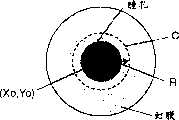
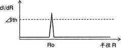
图2A是表示包含瞳孔的图像的一例的图。FIG. 2A is a diagram showing an example of an image including pupils.
图2B是表示对于积分圆的半径的积分值的图。FIG. 2B is a graph showing integral values with respect to the radius of the integrating circle.
图2C是表示用积分圆的半径对积分值进行微分后的值的图。FIG. 2C is a graph showing the value obtained by differentiating the integrated value with the radius of the integrating circle.
图2D是表示在眼睛图像上移动的积分圆的图。FIG. 2D is a diagram showing an integrating circle moving on an eye image.
图3A是表示积分圆位于虹膜区域时的眼睛图像及此时的辉度的一例的图。3A is a diagram showing an example of an eye image when the integrating circle is located in the iris region and the luminance at that time.
图3B是表示积分圆位于眼镜框上时的眼睛图像及此时的辉度的一例的图。3B is a diagram showing an example of an eye image when an integrating circle is positioned on a spectacle frame and the luminance at that time.
图4是同一实施例的瞳孔检测装置的电路框图。Fig. 4 is a circuit block diagram of the pupil detection device of the same embodiment.
图5是同一实施例的图像数据提取部的电路图。Fig. 5 is a circuit diagram of an image data extraction unit in the same embodiment.
图6是同一实施例的瞳孔候补保持部和瞳孔选择部的电路框图。6 is a circuit block diagram of a pupil candidate holding unit and a pupil selection unit in the same embodiment.
图7是用于说明同一实施例的瞳孔选择部的动作的图。Fig. 7 is a diagram for explaining the operation of the pupil selection unit in the same embodiment.
图8是表示同一实施例的瞳孔检测装置的眼睛图像的1帧的动作的流程图。Fig. 8 is a flowchart showing the operation of one frame of an eye image of the pupil detection device of the same embodiment.
图9是本发明的另一实施例中的用于从瞳孔候补中选择瞳孔的流程图。FIG. 9 is a flowchart for selecting pupils from pupil candidates in another embodiment of the present invention.
标记说明Mark description
120拍摄部120 shooting department
130照明部130 Department of Lighting
140认证处理部140 Authentication Processing Department
200瞳孔检测装置200 pupil detection device
220图像数据提取部220 Image Data Extraction Department
230环圆周积分部230 Circumference Integral Division
240辉度差算出部240 luminance difference calculation part
250变化圆检测部250 change circle detection unit
260指针部260 pointer department
280瞳孔候补保持部280 Pupil candidate maintenance department
290瞳孔选择部290 Pupil Selection Department
具体实施方式Detailed ways
本发明的瞳孔检测装置,具备:从眼睛图像中检测能够成为瞳孔的候补的瞳孔候补的位置的瞳孔候补检测部;保持多个瞳孔候补检测部所检测出的瞳孔候补的位置的瞳孔候补保持部;以及将被保持在瞳孔候补保持部的瞳孔候补之中的、在距离瞳孔候补的中心位置指定的距离或指定的距离以内的区域存在其它的瞳孔候补的中心位置的瞳孔候补选择为瞳孔的瞳孔选择部。利用这种结构,能够提供出能够精度良好且高速地进行瞳孔位置的检测的瞳孔检测装置。The pupil detection device of the present invention includes: a pupil candidate detection unit that detects the position of a pupil candidate that can be a pupil candidate from an eye image; and a pupil candidate holding unit that holds the positions of the pupil candidates detected by the plurality of pupil candidate detection units. ; and among the pupil candidates held in the pupil candidate holding section, there are other pupil candidates in the central position within the distance specified from the center position of the pupil candidate or within the specified distance, and the pupil candidate selected as the pupil of the pupil Select Ministry. With such a configuration, it is possible to provide a pupil detection device capable of detecting the pupil position with high accuracy and at high speed.
此外,本发明的瞳孔检测装置,具备:将同心圆状的多个圆分别作为积分圆设定在眼睛图像上,并提取位于上述积分圆的圆周上的眼睛图像的图像数据的图像数据提取部;将图像数据提取部提取的图像数据沿着积分圆中的每一者的圆周进行积分的环圆周积分部;从上述多个积分圆中检测上述环圆周积分部的积分值相对于积分圆的半径阶跃状地变化的积分圆的变化圆检测部;将由变化圆检测部检测出的积分圆的中心坐标作为瞳孔候补的坐标位置进行保持的瞳孔候补保持部;以及选择由瞳孔候补保持部所保持的瞳孔候补之中的、在距离瞳孔候补的中心坐标指定的距离或指定的距离以内的区域存在其它的瞳孔候补的中心位置的瞳孔候补的瞳孔选择部。利用这种结构,能够使用规模比较小的电路对于由拍摄部拍摄的图像数据实时地进行瞳孔检测。In addition, the pupil detection device of the present invention includes: an image data extraction unit that sets a plurality of concentric circles as integrating circles on the eye image, and extracts image data of the eye image located on the circumference of the integrating circles. ; a ring-circumference integrating unit that integrates the image data extracted by the image data extracting unit along the circumference of each of the integrating circles; detecting the integral value of the above-mentioned ring-circumferential integrating unit with respect to the integrating circle from among the plurality of integrating circles A changing circle detecting section of an integrating circle whose radius changes stepwise; a pupil candidate holding section that holds the center coordinates of the integrating circle detected by the changing circle detecting section as the coordinate position of the pupil candidate; Among the retained pupil candidates, the pupil selection unit of the pupil candidate at the center position of another pupil candidate exists in an area within the specified distance from the center coordinate of the pupil candidate or within the specified distance. With such a configuration, pupil detection can be performed in real time on the image data captured by the imaging unit using a relatively small-scale circuit.
此外,本发明的瞳孔检测装置的变化圆检测部,将环圆周积分部的积分值相对于积分圆的半径阶跃状地进行变化的变化大小作为评价值输出;瞳孔候补保持部,将检测输入数据中的具有最大值的数据的最大值检测器多个串联地连接而构成,其通过向瞳孔候补保持部输入评价值而按照评价值大的顺序保持瞳孔候补。利用这种结构,能够使用评价值按着大的顺序排列瞳孔候补。In addition, the changing circle detection part of the pupil detection device of the present invention outputs the magnitude of change in which the integrated value of the circular integration part changes stepwise with respect to the radius of the integrating circle as an evaluation value; the pupil candidate holding part outputs the detection input Among the data, a plurality of maximum value detectors of the data having the maximum value are connected in series, and the pupil candidates are held in order of larger evaluation values by inputting the evaluation values to the pupil candidate holding unit. With such a configuration, pupil candidates can be arranged in descending order using evaluation values.
此外,本发明的瞳孔检测装置的最大值检测器,也可以是如下的结构,具备:保持输入数据的寄存器、比较保持在寄存器内的数据和输入数据的比较器、以及选择并输出保持在寄存器内的数据或输入数据中的任何一者的选择器;寄存器,根据比较器的输出,当输入数据比所保持的数据大时,保持上述输入数据;选择器,根据比较器的输出,当输入数据比寄存器所保持的数据大时,选择寄存器所保持的数据,而当输入数据比寄存器所保持的数据小时,则选择输入数据。利用这种结构,能够用比较简单的电路实现最大值检测器。In addition, the maximum value detector of the pupil detection device of the present invention may also be configured as follows: a register holding input data, a comparator comparing the data held in the register with the input data, and selecting and outputting the data held in the register. A selector for any one of the data in or input data; the register, according to the output of the comparator, when the input data is larger than the data held, the above-mentioned input data is held; the selector, according to the output of the comparator, when the input When the data is larger than the data held by the register, the data held by the register is selected, and when the input data is smaller than the data held by the register, the input data is selected. With this configuration, the maximum value detector can be realized with a relatively simple circuit.
此外,本发明的瞳孔检测装置的瞳孔选择部,也可以是如下的结构,即、对于多个瞳孔候补,将相互距离接近的瞳孔候补作为1个组进行分组,从各自的组中选择瞳孔候补的数量最多的组、或瞳孔候补的评价值的总和最高的组,并从该被选择的组中决定瞳孔位置。利用这种结构,能够使用比较简单的算法实现瞳孔选择部。In addition, the pupil selection unit of the pupil detection device of the present invention may be configured such that, for a plurality of pupil candidates, pupil candidates close to each other are grouped as a group, and pupil candidates are selected from the respective groups. The group with the largest number or the group with the highest sum of evaluation values of pupil candidates is selected, and the pupil position is determined from the selected group. With such a configuration, the pupil selection unit can be realized using a relatively simple algorithm.
本发明的虹膜认证装置,具备本发明的瞳孔检测装置。利用这种结构,能够提供出装载了能够精度良好且高速地进行瞳孔位置的检测的瞳孔检测装置的虹膜认证装置。The iris authentication device of the present invention includes the pupil detection device of the present invention. With such a configuration, it is possible to provide an iris authentication device equipped with a pupil detection device capable of detecting the pupil position with high precision and high speed.
下面,使用附图对使用本发明的实施例的瞳孔检测装置的虹膜认证装置进行说明。Next, an iris authentication device using a pupil detection device according to an embodiment of the present invention will be described with reference to the drawings.
(实施例1)(Example 1)
图1是使用本发明的实施例1的瞳孔检测装置200的虹膜认证装置100的电路框图。在图1中,除了瞳孔检测装置200之外,还表示出用于构成虹膜认证装置100所需要的拍摄部120、照明部130和认证处理部140。FIG. 1 is a circuit block diagram of an
实施例1的虹膜认证装置100,具备:拍摄使用者的眼睛图像的拍摄部120;从眼睛图像中检测瞳孔位置及其半径的瞳孔检测装置200;将从眼睛图像得到的虹膜代码与已经登录的虹膜代码进行比较以进行个人认证的认证处理部140;照射适于取得眼睛图像的光量的近红外线而对使用者的眼睛及其周边部分进行照明的照明部130。The
拍摄部120,具有引导反射镜121、可见光截止滤光器122、透镜123、拍摄元件124和前处理部125。在实施例中,通过作为透镜123使用固定焦点透镜来实现光学系统的小型、轻量化和低成本化。引导反射镜121,通过使用者映入自己的眼睛而将眼睛向正确的拍摄位置引导。The
并且,使用者的眼睛通过透镜123、可见光截止滤光器122由拍摄元件124进行拍摄。前处理部125,从拍摄元件124的输出信号中取出图像数据成分,在作为增益调整等图像数据进行了需要的处理的基础上,作为使用者的眼睛图像数据输出。In addition, the user's eyes are photographed by the
瞳孔检测装置200,具有瞳孔候补检测部210、瞳孔候补保持部280、以及瞳孔选择部290,其从眼睛图像中检测出瞳孔位置及其半径并向认证处理部140输出。The
认证处理部140,根据瞳孔检测装置200所检测出的瞳孔中心坐标和瞳孔半径,从眼睛图像数据中分出虹膜图像。然后,通过将虹膜图像变换成表示虹膜的模样的固有的虹膜代码,并将其与已经登录的虹膜代码进行比较来执行认证动作。The
下面,对瞳孔检测装置200的瞳孔检测方法进行说明。图2A~2D是用于说明本发明的实施例1的瞳孔检测装置200的瞳孔检测方法的图。图2A是表示包含瞳孔的图像的一例的图,图2B是表示对于积分圆的半径的积分值的图,图2C是表示用积分圆的半径对积分值进行微分后的值的图,图2D是表示在眼睛图像上移动的积分圆的图。Next, the pupil detection method of the
如图2A所示,包含瞳孔的图像,存在表示瞳孔的圆盘状的低辉度区域和在其外侧表示虹膜的圆环状的中辉度区域。因此,当以瞳孔中心的位置坐标(Xo,Yo)为中心沿着半径R的积分圆C的圆周对图像数据进行环圆周积分时,则如图2B所示,积分值I在瞳孔半径为Ro时阶跃状地进行变化。因此,通过求出用半径R对积分值I进行微分后的值dI/dR超过阈值(以下记为“差阈值”)ΔIth时的积分圆的半径,就能够知道瞳孔半径Ro。As shown in FIG. 2A , in an image including the pupil, there are a disk-shaped low-intensity region representing the pupil and a circular-shaped medium-intensity region representing the iris outside. Therefore, when taking the position coordinates (Xo, Yo) of the center of the pupil as the center, the image data is integrated around the circumference of the integrating circle C of radius R, then as shown in Figure 2B, the integral value I is at the pupil radius Ro changes in steps. Therefore, the pupil radius Ro can be known by obtaining the radius of the integrating circle when the value dI/dR obtained by differentiating the integrated value I with the radius R exceeds the threshold value (hereinafter referred to as "difference threshold value") ΔIth.
根据以上的思考方法,瞳孔检测装置200检测瞳孔的位置坐标(Xo,Yo)以及瞳孔半径Ro。首先,如图2D所示,在眼睛图像上设定中心坐标相等而半径不同的n个积分圆C1~Cn,对于各个积分圆Ci(i=1~n)积分位于其圆周上的图像数据。实际上是计算位于各个积分圆Ci的圆周上的像素的图像数据的平均值,或者,从位于圆周上的像素中选择一定数量(m个)的像素,加算其图像数据。Based on the above thinking method, the
在实施例1中,设同心圆状的积分圆的数量n为20,从位于各个积分圆Ci的圆周上的像素中选择m=8个像素,将加算其图像数据的环圆周积分的积分值设为I。这时,当积分圆C1~Cn的中心与瞳孔中心一致时,如上所述,由于对于各个积分圆Ci的积分值Ii阶跃状地进行变化,所以当求积分值Ii相对于半径R的差值ΔIi时,当半径R与瞳孔半径Ro相等时,就表示大的极大值。In Example 1, assuming that the number n of concentric integrating circles is 20, m=8 pixels are selected from the pixels located on the circumference of each integrating circleCi , and the integral of the circular integral of the image data is added. The value is set to 1. At this time, when the centers of the integrating circles C1 to Cn coincide with the pupil centers, as described above, since the integrated value Ii for each integrating circle Ci changes stepwise, when the integrated value Ii is relatively For the difference ΔIi of the radius R, when the radius R is equal to the pupil radius Ro, it shows a large maximum value.
然而,当积分圆C1~Cn的中心与瞳孔中心不一致时,由于积分值Ii缓慢地变化,所以差值ΔIi不表示大的值。因此,通过求出差值ΔIi表示比差阈值ΔIth大的值的积分圆Ci,就能够求出瞳孔的位置及其半径。However, when the centers of the integrating circles C1 to Cn do not coincide with the pupil centers, since the integrated value Ii changes slowly, the difference ΔIi does not show a large value. Therefore, by obtaining the integrating circle Ci whose difference value ΔIi is greater than the difference threshold value ΔIth, the position of the pupil and its radius can be obtained.
然后,使积分圆C1~Cn向眼睛图像上的各个位置移动,反复进行上述的动作。这样,通过求出差值ΔIi表示大的值时的积分圆Ci的中心坐标(X,Y)及此时的半径R,就能够求出瞳孔的位置坐标(Xo,Yo)和瞳孔的半径Ro。Then, the integrating circles C1 to Cn are moved to respective positions on the eye image, and the above-mentioned operation is repeated. In this way, by obtaining the central coordinates (X, Y) of the integrating circle Ci and the radius R at this time when the difference ΔIi shows a large value, the position coordinates (Xo, Yo) of the pupil and the position coordinates (Xo, Yo) of the pupil can be obtained. Radius Ro.
然而,由于图像的原因存在偶发性地差值ΔIi表示出大的值的可能性。特别是,虽然减小积分圆的数量n或在各个积分圆上选择的像素的数量m而能够减少计算量,从而能够进行高速的瞳孔检测,但相反,偶发性地差值ΔIi表示出大的值的可能性增高,而瞳孔检测精降低。为此,通过在瞳孔检测装置200中设置辉度差算出部240,对于积分圆Ci中的每一者求出圆周上的辉度的最大值与最小值之差Bi,仅仅在该差Bi小于指定的阈值(以下记为“辉度差阈值”)Bth的情况下,将积分值Ii或其差值ΔIi作为有效,就防止了瞳孔检测精度的降低。However, there is a possibility that the difference ΔIi occasionally shows a large value due to image reasons. In particular, although the amount of calculation can be reduced by reducing the number n of integrating circles or the number m of pixels selected on each integrating circle, and high-speed pupil detection can be performed, on the contrary, the difference ΔIi occasionally shows a large The value of the likelihood increases, while the pupil detection accuracy decreases. For this reason, by providing the luminance
图3A和图3B是用于说明辉度差算出部240的动作的图。图3A是表示积分圆位于虹膜区域时的眼睛图像及此时的辉度的一例的图,图3B是表示积分圆位于眼镜框上时的眼睛图像及此时的辉度的一例的图。3A and 3B are diagrams for explaining the operation of the luminance
当积分圆C1~Cn的中心与瞳孔中心一致时,由于各个积分圆Ci位于瞳孔区域内部、虹膜区域内部等辉度比较均匀的区域,所以圆周上的图像数据的辉度偏差小。在图3A中表示位于作为圆环状的中辉度区域的虹膜区域的积分圆。在该情况下,圆周上的辉度的最大值与最小值之差Bi小,成为小于等于辉度差阈值Bth。When the centers of the integrating circles C1 -Cn coincide with the center of the pupil, each integrating circle Ci is located in a relatively uniform luminance area such as the inside of the pupil area or the iris area, so the luminance deviation of the image data on the circumference is small. FIG. 3A shows an integrating circle located in the iris region, which is a ring-shaped medium-brightness region. In this case, the difference Bi between the maximum value and the minimum value of the luminance on the circumference is small, and becomes equal to or less than the luminance difference threshold value Bth.
但是,例如图3B所示,当积分圆C1~Cn的中心位于黑的眼镜框的一部分上时,由于圆周上的辉度在眼镜框上低而在皮肤的部分上变高,所以辉度的最大值与最小值之差Bi就变大。这样,通过求出各个积分圆Ci的圆周上的辉度的最大值与最小值之差Bi,并且仅仅在该差Bi比辉度差阈值Bth小的情况下,将积分值Ii或其差值ΔIi作为有效,就能够防止将眼镜框误判定为瞳孔等的误判定,从而能够防止瞳孔检测精度的降低。However, as shown in FIG. 3B, for example, when the centers of the integrating circles C1 to Cn are located on a part of the black spectacle frame, since the luminance on the circumference is low on the spectacle frame and high on the skin part, the luminance The difference Bi between the maximum value and the minimum value of the degree becomes larger. In this way, by obtaining the difference Bi between the maximum value and the minimum value of the luminance on the circumference of each integrating circle Ci , and only when the difference Bi is smaller than the luminance difference threshold value Bth, the integral value Ii If the difference ΔIi thereof is effective, it is possible to prevent false determination that the spectacle frame is mistakenly determined to be a pupil or the like, thereby preventing a decrease in pupil detection accuracy.
另外,优选地作为辉度差阈值Bth设定得比圆周上的辉度数据的所预料的偏差稍大。从经验方面来说,设定为比虹膜的平均辉度与瞳孔的平均辉度之差大,而比皮肤的平均辉度与瞳孔的平均辉度之差小即可。例如,在256灰度级的图像信号的情况下,由于瞳孔的平均辉度为40灰度级左右,虹膜的平均辉度为100灰度级左右,而皮肤的平均辉度为200灰度级左右,所以作为辉度差阈值Bth设定在60~160之间即可。In addition, it is preferable to set the luminance difference threshold value Bth slightly larger than the expected variation of the luminance data on the circumference. Empirically, it may be set to be larger than the difference between the average luminance of the iris and the average luminance of the pupil, and smaller than the difference between the average luminance of the skin and the average luminance of the pupil. For example, in the case of an image signal of 256 gray levels, since the average brightness of the pupil is about 40 gray levels, the average brightness of the iris is about 100 gray levels, and the average brightness of the skin is 200 gray levels. Therefore, it is only necessary to set between 60 and 160 as the luminance difference threshold Bth.
此外,作为差阈值Bth,由于积分圆位于瞳孔上时的积分值I大致为40×8=320,而积分圆位于虹膜上时的积分值I大致为100×8=800,所以,作为差阈值ΔIth,设定为其差480的一半左右、即设定为240左右即可。In addition, as the difference threshold value Bth, since the integral value I when the integrating circle is located on the pupil is approximately 40×8=320, and the integrated value I when the integrating circle is located on the iris is approximately 100×8=800, as the difference threshold value ΔIth may be set to about half of the difference of 480, that is, about 240.
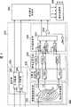
图4是本发明的实施例1的瞳孔检测装置200的电路框图。瞳孔检测装置200,具备:瞳孔候补检测部210、瞳孔候补保持部280和瞳孔选择部290。FIG. 4 is a circuit block diagram of
瞳孔候补检测部210,具备:将积分圆C1~Cn设定到眼睛图像上并提取各个积分圆Ci的圆周上的图像数据的图像数据提取部220、对所提取的图像数据以每个积分圆Ci的方式进行环圆周积分的环圆周积分部230、以每个积分圆的方式求出图像数据的最大值与最小值之差Bi的辉度差算出部240、求出积分值Ii对于半径Ri的差值ΔIi并输出当差值的最大值ΔI大于差阈值ΔIth时的差值ΔIi和积分圆的半径R的变化圆检测部250、以及表示积分圆C1~Cn的中心坐标(X,Y)的指针部260。The pupil
瞳孔候补保持部280,在变化圆检测部250输出比差阈值ΔIth大的差值ΔIi时,将其看作检测出瞳孔候补的结果,并存储多个瞳孔候补的位置坐标(X,Y)和半径R,瞳孔选择部290,从多个瞳孔候补中选择出1个瞳孔。The pupil
图5是图像数据提取部220的电路图。同时,在图5中还表示出与1个积分圆Ci对应的加法器230i和辉度差算出器240i。图像数据提取部220由部分帧存储器222及用于从其中引出(取出)图像数据的引出线L构成。FIG. 5 is a circuit diagram of the image
部分帧存储器222,是将先进先出(FIFO型)的行存储器224多个串联连接起来的存储器。并且,利用引出线Li在图像上从与积分圆Ci对应的m个像素中引出图像数据。另外,为了便于看图,虽然在图5中仅表示出1个积分圆Ci和引出位于其圆周上的4个图像数据的引出线Li,但在实施例1中,从20个积分圆C1~C20中引出了各自8个的数据的引出线。The
并且,由于每次当向部分帧存储器222内每1个像素地输入图像数据后,被保持在部分帧存储器222内的图像全体就每1个像素地进行移位,因此,从引出线Li引出的图像数据也每1个像素地进行移位。即,当向部分帧存储器222输入1个像素的量的图像数据后,在眼睛图像上积分圆C1~Cn就向右移动1个像素的量,而当输入1行的图像数据后,在眼睛图像上,积分圆C1~Cn就向下移动1行的量。Furthermore, since the entire image held in the
这样,在向部分帧存储器222输入1帧的图像数据的期间内,在眼睛图像上,积分圆C1~Cn就扫描眼睛图像全体。这时的积分圆的中心坐标(X,Y)由X计数器262和Y计数器264的输出表示。In this manner, while the image data of one frame is input to the
环圆周积分部230具备相对于积分圆C1~Cn中的每一者独立的加法器230i~230n,其加算位于各个积分圆Ci的圆周上的m个图像数据,并将各自的加算结果作为积分值Ii向变化圆检测部250输出。
辉度差算出部240,具备相对于积分圆C1~Cn中的每一者独立的辉度差算出器240i~240n,各个辉度差算出器240i都具备检测位于积分圆Ci的圆周上的m个图像数据的最大值的最大值检测器241i、检测最小值的最小值检测器242i、计算最大值与最小值之差Bi的减法器243i、对差Bi及辉度差阈值Bth进行比较的比较器244i。并且,向变化圆检测部250输出n个比较结果。The
变化圆检测部250,具备减法器252i~252n-1、选择器253、比较器254。减法器252i求对于各个积分圆Ci的积分值Ii相对于半径R的差。即,求对于积分圆C1~Cn之中的半径1个数不同的积分圆Ci与Ci-1的积分值Ii与Ii-1的差值ΔIi。但是,当对于积分圆Ci的图像数据的最大值与最小值之差Bi大于辉度差阈值Bth时,则强制性地将差值ΔIi设定为0。The changing
然后,选择器253和比较器254,向瞳孔候补保持部280输出差值ΔIi大于差阈值ΔIth的积分圆C的半径R,并且作为评价值Jo还向瞳孔候补保持部280输出该差值ΔI。这时,由于当对于积分圆Ci的图像数据的最大值与最小值之差Bi大于辉度差阈值Bth时,减法器252i强制性地将差值ΔIi设定为0,所以在差Bi大于辉度差阈值Bth的情况下,就不会向瞳孔候补保持部280输出半径Ri。Then, the
如使用图3说明的那样,当积分圆C1~Cn的中心与瞳孔的中心一致时,像素数据的最大值与最小值之差Bi将成为小于等于某一限定的值。但是,当与瞳孔的中心不一致时,差Bi将增大。因此,通过去除差Bi比辉度差阈值ΔIth大时的信息,能够减少误检测的可能性,从而能够提高瞳孔检测精度。As described using FIG. 3 , when the centers of the integrating circles C1 to Cn coincide with the center of the pupil, the difference Bi between the maximum value and the minimum value of pixel data becomes a value equal to or less than a certain limit. However, when it does not coincide with the center of the pupil, the differenceBi will increase. Therefore, by removing information when the difference Bi is larger than the luminance difference threshold value ΔIth, the possibility of erroneous detection can be reduced, and the pupil detection accuracy can be improved.
图6是瞳孔候补保持部280与瞳孔选择部290的电路框图。瞳孔候补检测部280是多个最大值检测器2801~280k分别被串联连接。最大值检测器280i中的每一者都具备:保持瞳孔候补的X坐标、Y坐标、半径R和评价值J的最大值的寄存器282i、283i、284i和285i;对输入的评价值Ji-1和保持在寄存器285i内的评价值Ji进行比较的比较器281i;选择输入的X坐标、Y坐标、半径R以及评价值J和所保持的X坐标、Y坐标、半径R以及评价值J中的任何一者的选择器286i、287i、288i和289i。FIG. 6 is a circuit block diagram of the pupil
向开头的最大值检测器2801中输入表示积分圆的坐标的X计数器262和Y计数器264的输出Xo、Yo,并输入变化圆检测部250的输出Ro。The output Xo, Yo of the
然后,当从变化圆检测部250输出的评价值Jo比寄存器2851所保持的评价值J1大时,则通过选择器2861~2891向第2个最大值检测器2802输出到此为止保持在寄存器2821~2851中的X坐标X1、Y坐标Y1、半径R1和评价值J1,并且,将新输入的X坐标Xo、Y坐标Yo、半径Ro和评价值Jo保持在寄存器2821~2851内。Then, when the evaluation value Jo output from the changing
当评价值Jo小于等于评价值J1时,则通过选择器2861~2891向第2个最大值检测器2802输出新输入的X坐标Xo、Y坐标Yo、半径Ro和评价值Jo。When the evaluation value Jo is less than or equal to theevaluation value J1 , thenewly input X coordinate Xo, Y coordinate Yo , radius Ro and Evaluation value Jo .
第2个最大值检测器2802,当从第1个最大值检测器2801输出的评价值J1大于寄存器2852所保持的评价值J2时,则向第3个最大值检测器2803输出到此为止保持在寄存器2822~2852中的X坐标X2、Y坐标Y2、半径R2和评价值J2,并且将新输入的X坐标X1、Y坐标Y1、半径R1和评价值J1保持在寄存器2822~2852内。当评价值J1小于等于评价值J2时,则向第3个最大值检测器2803输出新输入的X坐标X1、Y坐标Y1、半径R1和评价值J1。The second
以下同样,第i个最大值检测器280i,当从上游侧的最大值检测器280i-1输出的评价值Ji-1比到此为止所保持的评价值Ji大时,则向下游侧的最大值检测器280i+1输出到此为止所保持的数据,并且保持上游侧的数据。当评价值Ji-1小于等于评价值Ji时,则向下游侧输出上游侧的数据。Similarly, when the i-th
其结果,在开头的最大值检测器2801内保持对于评价值最大的瞳孔候补的X坐标X1、Y坐标Y1、半径R1和评价值J1,在第2个最大值检测器2802内保持对于第2个评价值大的瞳孔候补的X坐标X2、Y坐标Y2、半径R2和评价值J2,在第i个最大值检测器280i内保持对于第i个评价值大的瞳孔候补的X坐标Xi、Y坐标Yi、半径R1和评价值Ji。As a result, the X-coordinate X1 , Y-coordinate Y1 , radius R1 , and evaluation value J1 of the pupil candidate with the largest evaluation value are held in the first
瞳孔选择部290,从被保持在瞳孔候补保持部280内的多个瞳孔候补中选择出1个在距离瞳孔候补的中心位置指定的距离或指定的距离以内的区域存在其它的瞳孔候补的中心位置的瞳孔候补,并将其位置坐标和半径作为瞳孔的位置坐标和半径向认证处理部140输出。在本实施例中,将指定的距离设为1.5个像素。因此,瞳孔选择部290,对于瞳孔候补中的每一者,计数在与瞳孔候补的位置坐标(Xi,Yi)相邻的上下左右的4个像素和斜向方向的4个像素的共计8处的像素位置上包含的瞳孔候补的数量,并将此时包含最多的瞳孔候补的瞳孔候补选择为真的瞳孔。The
在存在多个包含最多的瞳孔候补的瞳孔候补的情况下,则将这些瞳孔候补之中的评价值Ji最大的瞳孔候补选择为真的瞳孔。其结果,由瞳孔选择部290选择的瞳孔,成为在其周围存在其它的瞳孔候补的瞳孔。虽然瞳孔选择部290也可以使用进行以上的动作的专用电路构成,但在本实施例中,使用设置在认证处理部140内的CPU(未图示)进行上述的处理。If there are a plurality of pupil candidates including the most pupil candidates, the pupil candidate with the largest evaluation value Ji among these pupil candidates is selected as the true pupil. As a result, the pupil selected by the
图7是用于说明瞳孔选择部290的动作的图。瞳孔候补P1、P2是错误地将睫毛检测为瞳孔的瞳孔候补,瞳孔候补P3~P11是检测出真的瞳孔的瞳孔候补。这样,通常被误检测出的瞳孔候补大部分不会密集,但却有在真的瞳孔的周围瞳孔候补密集的倾向。这种倾向依赖于瞳孔候补的检测精度,检测精度越好则密集的瞳孔候补的数量就越少。FIG. 7 is a diagram for explaining the operation of the
但是,即使提高了精度,由于还会存在依赖于拍摄元件的1个像素左右的误差,所以在与真的瞳孔的中心位置相邻的像素位置上存在其它的瞳孔候补的中心的可能性高。因此,通过将在周围存在其它的瞳孔候补的瞳孔候补选择为真的瞳孔,能够消除错将睫毛等检测为瞳孔等的误检测,从而能够提高瞳孔的检测精度。However, even if the accuracy is improved, there is still an error of about one pixel depending on the imaging device, so there is a high possibility that another pupil candidate center exists at a pixel position adjacent to the real pupil center position. Therefore, by selecting a pupil candidate surrounded by other pupil candidates as a real pupil, it is possible to eliminate false detections in which eyelashes and the like are mistakenly detected as pupils, thereby improving pupil detection accuracy.
在此,优选地由瞳孔候补保持部280检测的瞳孔候补的数量k、以及用于由瞳孔选择部290计数在周围存在的瞳孔候补的数量的像素位置的数量,由瞳孔候补的检测精度、被误检测的瞳孔候补的数量的估计等来决定。在本实施例中,预计在真的瞳孔的位置的上下左右聚集了各1个的瞳孔候补的可能性,作为用于计数瞳孔候补的数量的像素位置的数量,设定了包括上下左右4个像素和斜向方向4个像素的共计8个像素的区域。此外,在真的瞳孔的位置上集中有9个(真的瞳孔1个,上下左右各1个,斜向方向各1个)瞳孔候补,并假定被误检测的瞳孔候补最多存在6个,从而将检测的瞳孔候补的数量k设定为15。Here, it is preferable that the number k of pupil candidates detected by the pupil
这样,通过从眼睛图像中检测出多个瞳孔候补,并从多个瞳孔候补中选择在与瞳孔候补的中心位置相邻的像素位置上存在其它的瞳孔候补的中心位置的瞳孔候补,能够消除错误地将睫毛等检测为瞳孔等的误检测,从而能够提高瞳孔检测精度。In this way, by detecting a plurality of pupil candidates from the eye image, and selecting a pupil candidate whose center position has another pupil candidate at a pixel position adjacent to the center position of the pupil candidate from the plurality of pupil candidates, errors can be eliminated. Eyelashes and the like are detected as false detections of pupils and the like so that pupil detection accuracy can be improved.
接下来,对瞳孔检测装置200的动作进行说明。在以下的说明中,设眼睛图像数据是顺序扫描数据,设1帧由例如480行×640像素的数字数据构成。图8是表示本发明的实施例1的瞳孔检测装置200的眼睛图像1帧的动作的流程图。Next, the operation of the
首先,瞳孔检测装置200取入1个像素的量的图像数据(S51)。如果取入的图像数据是1帧的开头的数据(S52),则使Y计数器264复位并且使瞳孔候补保持部280的各个寄存器282~285复位(S53)。如果取入的数据是1行的开头的数据(S54),则使X计数器262复位,并使Y计数器264加1(S55)。然后,使X计数器262加1(S56)。First, the
接着,将取入的图像数据取入到部分帧存储器222内。之后,在眼睛图像上,从与n个积分圆C1~Cn对应的像素之中的各个积分圆Ci中每m个地引出n×m个图像数据。然后,与各个积分圆Ci对应的加法器230i分别计算图像数据的积分值Ii,辉度差算出器240i计算图像数据的最大值与最小值之差Bi。变化圆检测部250计算各自的积分值Ii的差值ΔIi。但此时,当差Bi比辉度差阈值Bth大时,则强制性地使差值ΔIi为0(S57)。Next, the captured image data is loaded into the
然后,比较器254对差值ΔIi和差阈值ΔIth进行比较(S58),当差值ΔIi比差阈值ΔIth大时,瞳孔候补保持部280将此时的X计数器262、Y计数器264和积分圆的半径Ro作为瞳孔候补保持,并且也将其差值ΔIi作为评价值Jo保持。这时,瞳孔候补保持部280,按照评价值大的顺序重新排列瞳孔候补并保持最多k个瞳孔候补(S59)。接着,判定取入的数据是否是1帧的末尾的数据(S60),如果不是末尾,则返回步骤S51。Then, the
当输入的图像数据为1帧的最后的像素的数据时,瞳孔选择部290,针对各自的瞳孔候补,计算在与其中心坐标相邻的像素位置上存在的其它的瞳孔候补的数量,并将该值最大的瞳孔候补的X坐标、Y坐标和半径的值作为真的瞳孔的X坐标Xo、Y坐标Yo和瞳孔半径R0向虹膜认证处理部140输出(S61)。When the input image data is data of the last pixel of one frame, the
以上的从步骤51到步骤60的一连串的动作,向部分帧存储器222每输入1个像素的量的图像数据地来执行。例如,在帧频为30Hz,眼睛图像由640×480像素构成的情况下,在小于等于1/(30×640×480)秒的时间内执行上述的一连串的动作。并且,由于当向部分帧存储器222输入1个像素后积分圆就在图像上移动1个像素的量,所以在输入1帧的图像的期间内积分圆在图像上进行1次扫描。这样,能够使用比较小规模的电路,对于由拍摄部120拍摄的图像数据实时地进行瞳孔检测。The above-described series of operations from step 51 to step 60 are executed every time image data corresponding to one pixel is input to the
另外,从多个瞳孔候补中选择在距离中心位置指定的距离或指定的距离以内的附近存在其它的瞳孔候补的中心位置的瞳孔候补的方法,并不限于上述的方法。例如,也可以采用这样的结构,即、对于多个瞳孔候补,将相互距离接近的瞳孔候补作为1个组进行分组,并且将各自的组所包含的瞳孔候补的数量多的组、或者所含有的瞳孔候补的评价值高的组等作为线索,来选择真的瞳孔。图9是基于这样的思考方法的用于从瞳孔候补中选择瞳孔的流程图。In addition, the method of selecting the pupil candidate at the center position where there are other pupil candidates within a specified distance from the center position or within the specified distance from the plurality of pupil candidates is not limited to the above-mentioned method. For example, it is also possible to employ a configuration in which, for a plurality of pupil candidates, pupil candidates whose distances are close to each other are grouped as one group, and groups with a large number of pupil candidates contained in each group, or groups contained in The group whose pupil candidate has a high evaluation value is used as a clue to select the real pupil. FIG. 9 is a flowchart for selecting pupils from pupil candidates based on such a way of thinking.
首先,瞳孔选择部290取入1个瞳孔候补。设取入的瞳孔候补的X坐标、Y坐标、半径和评价值分别为Xi、Yi、Ri和Ji(S71)。接着,针对X坐标、Y坐标和半径中的每一者,查找是否存在瞳孔候补的值Xi、Yi和Ri与组的平均值Xgj、Ygj和Rgj(j是0或正整数)之差比指定的阈值Xth、Yth和Rth小的组。即,查找是否存在满足|Xi-Xgj|<Xth、|Yi-Ygj|<Yth、|Ri-Rgj|<Rth的组(S72)。First, the
当存在时,在将在步骤S71取入的瞳孔候补追加到该组中(S73),当不存在时,则创建仅包括在步骤S71取入的瞳孔候补的新的组(S74)。接着,对于在步骤S73追加了瞳孔候补的组或在步骤S74新创建的组,进行平均值Xgj、Ygj和Rgj的再计算(S75)。If it exists, the pupil candidate acquired in step S71 is added to this group (S73), and when it does not exist, a new group including only the pupil candidate acquired in step S71 is created (S74). Next, the average values Xgj, Ygj, and Rgj are recalculated for the group to which pupil candidates were added in step S73 or the group newly created in step S74 (S75).
当残存尚未分组的瞳孔候补时,则返回步骤S71(S76)。当所有的瞳孔候补的分组结束后,对于各自的组求包含在该组内的各个瞳孔候补的评价值的总和∑J(S77)。然后,将评价值的总和∑J为最大的组的X坐标、Y坐标和半径的平均值Xgj、Ygj和Rgj作为瞳孔的X坐标、Y坐标和半径向虹膜认证处理部140输出(S78)。When pupil candidates not yet grouped remain, the process returns to step S71 (S76). When the grouping of all the pupil candidates is completed, the sum ΣJ of the evaluation values of the respective pupil candidates included in the group is calculated for each group (S77). Then, the average values Xgj, Ygj, and Rgj of the X-coordinate, Y-coordinate, and radius of the group whose sum ΣJ of evaluation values is the largest are output to the iris
按照以上的方法,虽然原理上由于瞳孔候补的顺序而存在分组的结果发生变化等的不稳定性,但由于被误检测出的瞳孔候补是孤立的,而包含真的瞳孔的瞳孔候补的集合是密集的,所以只要例如将Xth、Yth的值设定为所预计的瞳孔半径的1/2左右,实际上不会发生问题。此外,按照该流程,数据处理比较简单,从而适于高速动作。According to the above method, although in principle there is instability in the result of grouping due to the order of the pupil candidates, such as changes, but because the pupil candidates that are falsely detected are isolated, the set of pupil candidates that include true pupils is Since they are dense, for example, if the values of Xth and Yth are set to about 1/2 of the expected pupil radius, practically no problem will occur. In addition, according to this flow, data processing is relatively simple, which is suitable for high-speed operation.
此外,本实施例的变化圆检测部250的选择器253,具有选择差值ΔIi的最大值和此时的积分圆C的半径R的功能。然而,瞳孔候补保持部280原本就具有检测最大值的功能。因此,作为选择器253,也可以采用单纯地以分时的方式将减法器2521~252n-1的输出和积分圆的半径输出的结构。In addition, the
另外,在本实施例中,虽然将同心圆状的积分圆的数量设为20,将从1个积分圆引出的图像数据的数量设为8个,但是,优选地这些数量兼顾检测精度、处理时间、电路规模等地进行决定。In addition, in this embodiment, although the number of concentric integrating circles is set to 20, and the number of image data drawn from one integrating circle is set to 8, it is preferable that these numbers balance detection accuracy and processing. Time, circuit scale, etc. are determined.
按照本发明,能够提供出能够精度良好且高速地进行瞳孔位置的检测的瞳孔检测装置和虹膜认证装置。According to the present invention, it is possible to provide a pupil detection device and an iris authentication device capable of detecting the pupil position with high precision and high speed.
工业上利用的可能性。Possibility of industrial use.
由于本发明能够提供出能够精度良好且高速地进行瞳孔位置检测的瞳孔检测装置,所以作为个人认证等所使用的虹膜认证装置是有用的。Since the present invention can provide a pupil detection device capable of detecting the pupil position with high accuracy and high speed, it is useful as an iris authentication device used for personal authentication and the like.
Claims (6)
Translated fromChineseApplications Claiming Priority (2)
| Application Number | Priority Date | Filing Date | Title |
|---|---|---|---|
| JP2004206932AJP3966309B2 (en) | 2004-07-14 | 2004-07-14 | Pupil detection device and iris authentication device |
| JP206932/2004 | 2004-07-14 |
Publications (2)
| Publication Number | Publication Date |
|---|---|
| CN1805702A CN1805702A (en) | 2006-07-19 |
| CN100403973Ctrue CN100403973C (en) | 2008-07-23 |
Family
ID=35783655
Family Applications (1)
| Application Number | Title | Priority Date | Filing Date |
|---|---|---|---|
| CNB2005800005451AExpired - Fee RelatedCN100403973C (en) | 2004-07-14 | 2005-05-18 | Pupil detection device and iris authentication device |
Country Status (5)
| Country | Link |
|---|---|
| US (1) | US20070036396A1 (en) |
| EP (1) | EP1767141A4 (en) |
| JP (1) | JP3966309B2 (en) |
| CN (1) | CN100403973C (en) |
| WO (1) | WO2006006298A1 (en) |
Families Citing this family (26)
| Publication number | Priority date | Publication date | Assignee | Title |
|---|---|---|---|---|
| US8090157B2 (en)* | 2005-01-26 | 2012-01-03 | Honeywell International Inc. | Approaches and apparatus for eye detection in a digital image |
| WO2005086802A2 (en) | 2004-03-08 | 2005-09-22 | Proxense, Llc | Linked account system using personal digital key (pdk-las) |
| US11206664B2 (en) | 2006-01-06 | 2021-12-21 | Proxense, Llc | Wireless network synchronization of cells and client devices on a network |
| US8219129B2 (en) | 2006-01-06 | 2012-07-10 | Proxense, Llc | Dynamic real-time tiered client access |
| US7904718B2 (en) | 2006-05-05 | 2011-03-08 | Proxense, Llc | Personal digital key differentiation for secure transactions |
| US9269221B2 (en) | 2006-11-13 | 2016-02-23 | John J. Gobbi | Configuration of interfaces for a location detection system and application |
| US8659427B2 (en) | 2007-11-09 | 2014-02-25 | Proxense, Llc | Proximity-sensor supporting multiple application services |
| US8171528B1 (en) | 2007-12-06 | 2012-05-01 | Proxense, Llc | Hybrid device having a personal digital key and receiver-decoder circuit and methods of use |
| US9251332B2 (en) | 2007-12-19 | 2016-02-02 | Proxense, Llc | Security system and method for controlling access to computing resources |
| WO2009102979A2 (en) | 2008-02-14 | 2009-08-20 | Proxense, Llc | Proximity-based healthcare management system with automatic access to private information |
| WO2009126732A2 (en) | 2008-04-08 | 2009-10-15 | Proxense, Llc | Automated service-based order processing |
| JP5365214B2 (en)* | 2009-01-22 | 2013-12-11 | 日本電気株式会社 | Image processing apparatus, biometric authentication apparatus, image processing method, and program |
| US9418205B2 (en) | 2010-03-15 | 2016-08-16 | Proxense, Llc | Proximity-based system for automatic application or data access and item tracking |
| US8918854B1 (en) | 2010-07-15 | 2014-12-23 | Proxense, Llc | Proximity-based system for automatic application initialization |
| US8857716B1 (en) | 2011-02-21 | 2014-10-14 | Proxense, Llc | Implementation of a proximity-based system for object tracking and automatic application initialization |
| IL215883A0 (en)* | 2011-10-24 | 2012-03-01 | Iriss Medical Technologies Ltd | System and method for indentifying eye conditions |
| JP2013215549A (en)* | 2012-03-16 | 2013-10-24 | Fujitsu Ltd | Image processing device, image processing program, and image processing method |
| WO2014183106A2 (en) | 2013-05-10 | 2014-11-13 | Proxense, Llc | Secure element as a digital pocket |
| JP6751324B2 (en)* | 2016-09-14 | 2020-09-02 | 株式会社デンソーアイティーラボラトリ | Iris detection device, iris detection method, and program |
| KR102369412B1 (en) | 2017-02-02 | 2022-03-03 | 삼성전자주식회사 | Device and method to recognize iris |
| US11003936B2 (en)* | 2019-06-14 | 2021-05-11 | Tobii Ab | Method and system for controlling an eye tracking system |
| WO2021171395A1 (en)* | 2020-02-26 | 2021-09-02 | 三菱電機株式会社 | Pupil position detection device, sight line detection device, and pupil position detection method |
| WO2021171396A1 (en)* | 2020-02-26 | 2021-09-02 | 三菱電機株式会社 | Pupil position detection device, visual line detection appratus, and pupil position detection method |
| CA3176950A1 (en)* | 2020-04-30 | 2021-11-04 | Neurotologix Pty Ltd | Method, system and apparatus for investigating or assessing eye or pupil movement |
| CN112464829B (en)* | 2020-12-01 | 2024-04-09 | 中航航空电子有限公司 | Pupil positioning method, pupil positioning equipment, storage medium and sight tracking system |
| KR102857951B1 (en) | 2021-10-06 | 2025-09-15 | 씨엠아이텍주식회사 | User authentication apparatus and method using combination of iris authentication and face authentication |
Citations (5)
| Publication number | Priority date | Publication date | Assignee | Title |
|---|---|---|---|---|
| US6144754A (en)* | 1997-03-28 | 2000-11-07 | Oki Electric Industry Co., Ltd. | Method and apparatus for identifying individuals |
| CN1282048A (en)* | 1999-07-22 | 2001-01-31 | 中国科学院自动化研究所 | Identity identifying method based on iris idendification and its equipment |
| JP2001167252A (en)* | 1999-12-10 | 2001-06-22 | Oki Electric Ind Co Ltd | Ophthalmic image preparing method, method and device for identifying iris |
| CN1422596A (en)* | 2000-08-09 | 2003-06-11 | 松下电器产业株式会社 | Eye position detection method and apparatus thereof |
| JP2004021406A (en)* | 2002-06-13 | 2004-01-22 | Matsushita Electric Ind Co Ltd | Eye position identification method and authentication device |
Family Cites Families (11)
| Publication number | Priority date | Publication date | Assignee | Title |
|---|---|---|---|---|
| US4641349A (en)* | 1985-02-20 | 1987-02-03 | Leonard Flom | Iris recognition system |
| US5291560A (en)* | 1991-07-15 | 1994-03-01 | Iri Scan Incorporated | Biometric personal identification system based on iris analysis |
| US6419638B1 (en)* | 1993-07-20 | 2002-07-16 | Sam H. Hay | Optical recognition methods for locating eyes |
| US6095989A (en)* | 1993-07-20 | 2000-08-01 | Hay; Sam H. | Optical recognition methods for locating eyes |
| US5481622A (en)* | 1994-03-01 | 1996-01-02 | Rensselaer Polytechnic Institute | Eye tracking apparatus and method employing grayscale threshold values |
| US5805745A (en)* | 1995-06-26 | 1998-09-08 | Lucent Technologies Inc. | Method for locating a subject's lips in a facial image |
| US7277561B2 (en)* | 2000-10-07 | 2007-10-02 | Qritek Co., Ltd. | Iris identification |
| JP2004240583A (en)* | 2003-02-04 | 2004-08-26 | Brother Ind Ltd | Image processing apparatus and image reading apparatus having the same |
| US7599524B2 (en)* | 2003-04-04 | 2009-10-06 | Sarnoff Corporation | Method and apparatus for providing a robust object finder |
| US20050031173A1 (en)* | 2003-06-20 | 2005-02-10 | Kyungtae Hwang | Systems and methods for detecting skin, eye region, and pupils |
| US7756301B2 (en)* | 2005-01-26 | 2010-07-13 | Honeywell International Inc. | Iris recognition system and method |
- 2004
- 2004-07-14JPJP2004206932Apatent/JP3966309B2/ennot_activeExpired - Fee Related
- 2005
- 2005-05-18USUS10/555,232patent/US20070036396A1/ennot_activeAbandoned
- 2005-05-18WOPCT/JP2005/009045patent/WO2006006298A1/ennot_activeCeased
- 2005-05-18CNCNB2005800005451Apatent/CN100403973C/ennot_activeExpired - Fee Related
- 2005-05-18EPEP05741518Apatent/EP1767141A4/ennot_activeWithdrawn
Patent Citations (5)
| Publication number | Priority date | Publication date | Assignee | Title |
|---|---|---|---|---|
| US6144754A (en)* | 1997-03-28 | 2000-11-07 | Oki Electric Industry Co., Ltd. | Method and apparatus for identifying individuals |
| CN1282048A (en)* | 1999-07-22 | 2001-01-31 | 中国科学院自动化研究所 | Identity identifying method based on iris idendification and its equipment |
| JP2001167252A (en)* | 1999-12-10 | 2001-06-22 | Oki Electric Ind Co Ltd | Ophthalmic image preparing method, method and device for identifying iris |
| CN1422596A (en)* | 2000-08-09 | 2003-06-11 | 松下电器产业株式会社 | Eye position detection method and apparatus thereof |
| JP2004021406A (en)* | 2002-06-13 | 2004-01-22 | Matsushita Electric Ind Co Ltd | Eye position identification method and authentication device |
Also Published As
| Publication number | Publication date |
|---|---|
| US20070036396A1 (en) | 2007-02-15 |
| EP1767141A4 (en) | 2009-08-05 |
| CN1805702A (en) | 2006-07-19 |
| EP1767141A1 (en) | 2007-03-28 |
| WO2006006298A1 (en) | 2006-01-19 |
| JP2006025969A (en) | 2006-02-02 |
| JP3966309B2 (en) | 2007-08-29 |
Similar Documents
| Publication | Publication Date | Title |
|---|---|---|
| CN100403973C (en) | Pupil detection device and iris authentication device | |
| US20220138490A1 (en) | Image processing apparatus, image processing method, and non-transitory computer-readable storage medium | |
| KR102393298B1 (en) | Method and apparatus for iris recognition | |
| CN108351961A (en) | Image and feature quality, image enhancement and feature extraction for eye vessel and face recognition and fusion of eye vessel and face and/or sub-face information for biometric systems | |
| US20140204238A1 (en) | Feature extraction apparatus, feature extraction program, and image processing apparatus | |
| CN100444778C (en) | Pupil detection device and iris authentication device | |
| CN109086734A (en) | The method and device that pupil image is positioned in a kind of pair of eye image | |
| JP2003317102A (en) | Pupil circle and iris circle detecting device | |
| Wang et al. | A real-time multi-face detection system implemented on FPGA | |
| KR101769741B1 (en) | Method and apparatus for recognizing iris through pupil detection | |
| EP1796033A1 (en) | Pupil dection device and iris authentication apparatus | |
| EP1796032A1 (en) | Pupil detection device and iris authentication apparatus | |
| WO2015031350A1 (en) | Systems and methods for memory utilization for object detection | |
| CN112233139A (en) | System and method for detecting motion during 3D data reconstruction | |
| JP4533836B2 (en) | Fluctuating region detection apparatus and method | |
| JP4151624B2 (en) | Pupil detection device, iris authentication device, and pupil detection method | |
| JP2006345891A (en) | Pupil detection device and iris authentication device | |
| JP2006260351A (en) | Pupil detection device with iris reflection detection function and iris authentication device | |
| KR0158416B1 (en) | Method of judging position of object by contraction of image data | |
| CN112102356A (en) | Target tracking method and device, terminal equipment and storage medium | |
| Mohammadi et al. | Comparative Study of Skeletonization and Radial Distance Methods for Automated Finger Enumeration | |
| JPH0525354B2 (en) | ||
| JPH01201788A (en) | Character reading method |
Legal Events
| Date | Code | Title | Description |
|---|---|---|---|
| C06 | Publication | ||
| PB01 | Publication | ||
| C10 | Entry into substantive examination | ||
| SE01 | Entry into force of request for substantive examination | ||
| C14 | Grant of patent or utility model | ||
| GR01 | Patent grant | ||
| C17 | Cessation of patent right | ||
| CF01 | Termination of patent right due to non-payment of annual fee | Granted publication date:20080723 Termination date:20100518 |