CN100400244C - Robot remote control system - Google Patents
Robot remote control systemDownload PDFInfo
- Publication number
- CN100400244C CN100400244CCNB038261146ACN03826114ACN100400244CCN 100400244 CCN100400244 CCN 100400244CCN B038261146 ACNB038261146 ACN B038261146ACN 03826114 ACN03826114 ACN 03826114ACN 100400244 CCN100400244 CCN 100400244C
- Authority
- CN
- China
- Prior art keywords
- robot
- arm
- remote control
- control data
- small
- Prior art date
- Legal status (The legal status is an assumption and is not a legal conclusion. Google has not performed a legal analysis and makes no representation as to the accuracy of the status listed.)
- Expired - Lifetime
Links
Images


Classifications
- B—PERFORMING OPERATIONS; TRANSPORTING
- B25—HAND TOOLS; PORTABLE POWER-DRIVEN TOOLS; MANIPULATORS
- B25J—MANIPULATORS; CHAMBERS PROVIDED WITH MANIPULATION DEVICES
- B25J9/00—Programme-controlled manipulators
- B25J9/16—Programme controls
- B25J9/1679—Programme controls characterised by the tasks executed
- B25J9/1689—Teleoperation
- B—PERFORMING OPERATIONS; TRANSPORTING
- B25—HAND TOOLS; PORTABLE POWER-DRIVEN TOOLS; MANIPULATORS
- B25J—MANIPULATORS; CHAMBERS PROVIDED WITH MANIPULATION DEVICES
- B25J13/00—Controls for manipulators
- B25J13/02—Hand grip control means
- B—PERFORMING OPERATIONS; TRANSPORTING
- B25—HAND TOOLS; PORTABLE POWER-DRIVEN TOOLS; MANIPULATORS
- B25J—MANIPULATORS; CHAMBERS PROVIDED WITH MANIPULATION DEVICES
- B25J3/00—Manipulators of leader-follower type, i.e. both controlling unit and controlled unit perform corresponding spatial movements
- B25J3/04—Manipulators of leader-follower type, i.e. both controlling unit and controlled unit perform corresponding spatial movements involving servo mechanisms
- B—PERFORMING OPERATIONS; TRANSPORTING
- B25—HAND TOOLS; PORTABLE POWER-DRIVEN TOOLS; MANIPULATORS
- B25J—MANIPULATORS; CHAMBERS PROVIDED WITH MANIPULATION DEVICES
- B25J5/00—Manipulators mounted on wheels or on carriages
- B25J5/005—Manipulators mounted on wheels or on carriages mounted on endless tracks or belts
- B—PERFORMING OPERATIONS; TRANSPORTING
- B25—HAND TOOLS; PORTABLE POWER-DRIVEN TOOLS; MANIPULATORS
- B25J—MANIPULATORS; CHAMBERS PROVIDED WITH MANIPULATION DEVICES
- B25J9/00—Programme-controlled manipulators
- B25J9/0084—Programme-controlled manipulators comprising a plurality of manipulators
- B25J9/0087—Dual arms
- G—PHYSICS
- G05—CONTROLLING; REGULATING
- G05B—CONTROL OR REGULATING SYSTEMS IN GENERAL; FUNCTIONAL ELEMENTS OF SUCH SYSTEMS; MONITORING OR TESTING ARRANGEMENTS FOR SUCH SYSTEMS OR ELEMENTS
- G05B2219/00—Program-control systems
- G05B2219/30—Nc systems
- G05B2219/40—Robotics, robotics mapping to robotics vision
- G05B2219/40174—Robot teleoperation through internet
Landscapes
- Engineering & Computer Science (AREA)
- Robotics (AREA)
- Mechanical Engineering (AREA)
- Manipulator (AREA)
Abstract
Description
Translated fromChinese技术领域technical field
本发明涉及进行以人为救助对象的救助或于危险场所进行修复作业的目的的,基于机器人遥控装置无线传送来的控制数据,进行机器人装置遥控的机器人遥控系统。The invention relates to a robot remote control system for remote control of a robot device based on the control data wirelessly transmitted from the robot remote control device for the purpose of rescue with people as rescue objects or repair work in dangerous places.
背景技术Background technique
作为遥控救助用机器人装置的遥控系统,例如有实开平6-68977号公报中所述的。As a remote control system for remotely controlling a rescue robot, there is, for example, one described in Japanese Patent Laid-Open Publication No. 6-68977.
此公报中所述机器人遥控系统的机器人装置是将救助对象载于台架上,在观察电视摄像机拍摄的图象同时,通过遥控的仿效机械手臂移动救助对象,将其载于台架上进行救助。The robot device of the robot remote control system described in this bulletin is to load the rescue object on the platform, and at the same time observe the image taken by the TV camera, move the rescue object through the imitation mechanical arm of the remote control, and load it on the platform for rescue. .
但是以往的机器人遥控系统中,用来将救助对象移到台架上的是进行大致移动的仿效机械手臂,对于需要灵巧的工作或撤除重物时,就有不能适应的问题。此外,还有不能对应危险场所的精细操作与撤除重物操作的问题。However, in the conventional robot remote control system, the imitation robot arm is used to move the rescued object to the gantry, and it cannot adapt to the dexterous work or the removal of heavy objects. In addition, there is a problem of not being able to cope with delicate operations in dangerous places and removal of heavy objects.
对这种机器人遥控系统,要求遥控机器人装置能进行灵巧的操作和撤除重物的操作。For such a robot remote control system, the remote robot device is required to be able to perform dexterous operations and operations for removing heavy objects.
发明内容Contents of the invention
本发明的目的即在于提供所遥控机器人装置去进行灵巧的操作与撤除重物操作的机器人遥控系统。The object of the present invention is to provide a robot remote control system for performing dexterous operation and removal of heavy objects by remote control of a robot device.
为了解决上述问题,本发明的机器人遥控系统是具有遥控机器人的机器人遥控装置与根据遥控装置的数据控制的机器人装置的机器人遥控系统,此系统包括:机器人遥控装置,它具有生成机器人装置的控制数据的第一计算机装置、将控制数据发送到与公共线路网连接的基地台的第一移动体通信装置;机器人装置;它具有接收与公共线路网连接的基地台发送来的控制数据的第二移动体通信装置、处理控制数据控制机械装置部的第二计算机装置;机械装置部,它具有由第二计算机装置控制的1~2个大操作臂和1~2个小操作臂以及移动系统;所述1~2个小操作臂配置在1~2个大操作臂的内侧;所述第二计算机装置根据机器人装置的控制数据,控制1~2个大操作臂和1~2个小操作臂以及移动系统。In order to solve the above-mentioned problems, the robot remote control system of the present invention is a robot remote control system with a robot remote control device for remote-controlling a robot and a robot device controlled according to the data of the remote control device. A first computer device, a first mobile communication device that sends control data to a base station connected to the public line network; a robot device; it has a second mobile device that receives control data sent from a base station connected to the public line network Body communication device, processing control data to control the second computer device of the mechanical device part; the mechanical device part has 1 to 2 large operating arms and 1 to 2 small operating arms and a moving system controlled by the second computer device; The 1 to 2 small operating arms are arranged inside the 1 to 2 large operating arms; the second computer device controls 1 to 2 large operating arms and 1 to 2 small operating arms and mobile system.
由此可以获得使遥控机器人装置能进行灵巧动作与撤除重物的机器人遥控系统。Thereby, a robot remote control system enabling a remote robot device to perform dexterous movements and remove heavy objects can be obtained.
本发明第1方面的机器人遥控系统是具有遥控机器人的机器人遥控装置和根据遥控装置的数据控制的机器人装置的机器人遥控系统,其中:机器人遥控装置具有生成机器人装置的控制数据的远程指令装置、将控制数据输入进行处理的第一计算机装置、将控制数据发送到与公共线路网连接的基地台的第一移动体通信装置;机器人装置具有接收与公用线路网连接的基地台发送来的控制数据的第二移动体通信装置、处理控制数据控制机械装置部的第二计算机装置;机械装置部具有由第二计算机装置控制的1~2个大操作臂和1~2个小操作臂以及移动系统;所述1~2个小操作臂配置在1~2个大操作臂的内侧;所述第二计算机装置则根据机器人装置的控制数据控制1~2个左操作臂和1~2个小操作臂以及移动系统。The robot remote control system according to the first aspect of the present invention is a robot remote control system having a robot remote control device for remote control of a robot and a robot device controlled according to data from the remote control device, wherein the robot remote control device has a remote instruction device for generating control data of the robot device, The first computer device that controls the data input for processing, the first mobile communication device that sends the control data to the base station connected to the public line network; the robot device has a device that receives the control data sent by the base station connected to the public line network The second mobile body communication device, the second computer device that processes and controls the data to control the mechanical device part; the mechanical device part has 1 to 2 large operating arms and 1 to 2 small operating arms and a moving system controlled by the second computer device; The 1-2 small operating arms are arranged inside the 1-2 large operating arms; the second computer device controls 1-2 left operating arms and 1-2 small operating arms according to the control data of the robot device and mobile systems.
根据以上结构,由于来自机器人遥控装置的控制数据是通过第一移动体通信装置传送,作为被控制体的机器人装置至少是即使配置于日本的任何地方,也能控制此机器人装置,同时由于机器人装置具有1~2个大操作臂和配置在所述1~2个大操作臂内侧的1~2个小操作臂,配置在所述1~2个小操作臂外侧的这1~2个大操作臂可用于进行撤除重物的工作,而配置在所述1~2个大操作臂内侧的这1~2个小操作臂则能进行灵巧的操作,故可用于进行迅速的救助活动。According to the above structure, since the control data from the robot remote control device is transmitted through the first mobile communication device, the robot device as the controlled object can control the robot device at least even if it is deployed anywhere in Japan. It has 1 to 2 large operating arms and 1 to 2 small operating arms arranged inside the 1 to 2 large operating arms, and the 1 to 2 large operating arms arranged outside the 1 to 2 small operating arms The arms can be used to remove heavy objects, and the 1 to 2 small operating arms arranged inside the 1 to 2 large operating arms can perform dexterous operations, so they can be used for rapid rescue activities.
这里的大操作臂与小操作臂可根据机器人的用途各设置一对,或也可设置1个大操作杆与一对小操作杆,等等。The large operating arm and the small operating arm here can be respectively provided with a pair according to the purposes of the robot, or one large operating rod and a pair of small operating rods can also be provided, and the like.
本发明第2方面所述的机器人遥控系统是在第1方面所述的遥控系统中,使此1~2个大操作臂和1~2个小操作臂分别具有基臂、支臂、手腕部与指部。The robot remote control system described in the second aspect of the present invention is in the remote control system described in the first aspect, so that the 1 to 2 large operating arms and the 1 to 2 small operating arms have base arms, support arms, and wrist parts respectively. and fingers.
根据上述结构,由于具有该1~2个大操作臂和该1~2个大操作臂内配置的1~2个小操作臂,配置于外侧的大操作臂可进行撤除重物工作的强有力的工作,而配置于内侧的1~2个小操作臂则可进行不需强力的灵巧操作,能用于可靠地进行迅速的救助活动。According to the above structure, since there are 1 to 2 large operating arms and 1 to 2 small operating arms disposed inside the 1 to 2 large operating arms, the large operating arm disposed on the outside can perform powerful work of removing heavy objects. The 1-2 small operating arms arranged on the inside can perform dexterous operations without strong force, and can be used for reliable and rapid rescue activities.
本发明第3方面的机器人遥控系统是在第1或2方面所述的机器人遥控系统中,由油压驱动1~2个大操作臂和移动系统而由电功率驱动1~2个小操作臂。The robot remote control system of the third aspect of the present invention is in the robot remote control system described in the first or second aspect, 1 to 2 large operating arms and moving systems are driven by hydraulic pressure, and 1 to 2 small operating arms are driven by electric power.
根据上述结构,由于油压驱动的大操作臂能可靠地进行撤除重物工作的强有力的工作,而电功率驱动的1~2个小操作臂能进行高精度的灵巧工作,就能用来高精度地和可靠地进行迅速的救助活动。According to the above structure, since the large operating arm driven by hydraulic pressure can reliably perform powerful work for removing heavy objects, and one or two small operating arms driven by electric power can perform dexterous work with high precision, it can be used for high-speed operation. Perform prompt rescue operations with precision and reliability.
本发明第4方面的机器人遥控系统是在第1~3方面中任一方面所述的机器人遥控系统中,使该移动系统为油压驱动的辊。A robot remote control system according to a fourth aspect of the present invention is the robot remote control system according to any one of the first to third aspects, wherein the moving system is a hydraulically driven roller.
根据上述结构,机器人装置即使在凹凸不平的道路和陡峭的坡地等难以行走的地形上,也能用来进行容易和高速的移动。According to the above structure, the robot apparatus can be used for easy and high-speed movement even on rough terrains such as uneven roads and steep slopes, which are difficult to walk on.
本发明第5方面的机器人遥控系统是在第1~4方面中任一方面所述的机器人遥控系统中,使机器人装置具有由移动系统驱动的移动台以及在移动台上的机室,而在机室内则具有控制这1~2个大操作臂和1~2个小操作臂以及移动系统的乘车用指令装置,该乘车指令装置具有切换遥控控制和乘车控制的遥控乘车变换开关。The robot remote control system of the fifth aspect of the present invention is in the robot remote control system described in any one of the first to fourth aspects, the robot device has a mobile platform driven by the mobile system and a machine room on the mobile platform, and In the machine room, there is a ride command device for controlling the 1~2 large operating arms and 1~2 small operating arms and the moving system. The ride command device has a remote control ride change switch for switching between remote control and ride control. .
根据上述结构,只切换遥控乘车变换开关,不仅是远地,即使在能搭乘的所谓机室附近处,也能用于容易地控制机器人装置。According to the above-mentioned structure, only switching the remote control ride changing switch can be used to easily control the robot device not only in a remote place but also in the vicinity of a so-called machine room where the robot can be boarded.
本发明第6方面的机器人遥控系统是在第1~5方面中任一方面所述的机器人遥控系统中,使机械装置部具有将对象物拍摄而变换为图像信号的多个摄像机、将周围发生的声音变换为音频信号的多个麦克风;第二计算机装置通过第二移动体通信装置发送图像信号与音频信号;机器人遥控装置接收第二移动体通信装置的发送信号,将图像信号于监视器上显示,将音频信号从扬声器作为声音发送出。A robot remote control system according to a sixth aspect of the present invention is the robot remote control system described in any one of
根据上述结构,即使在远地,由于能通过图像和声音了解机器人装置的状态,就可用于正确和迅速地控制机器人装置。According to the above structure, even in a remote place, since the state of the robot device can be known through images and sounds, it can be used to control the robot device correctly and quickly.
本发明第7方面的机器人遥控系统是在第1~6方面中任一方面所述的机器人遥控系统中,上述远程指令装置包括有:控制上述大操作臂自由旋转回转的大臂操作臂、控制上述小操作臂自由旋转回转的小臂操作臂、设于上述大操作臂与上述小操作臂上的多个传感器、执行开闭指令的多个指令开关,且根据多个传感器探测出的旋转转动值与多个指令开关的开闭生成机器人装置的控制数据。The robot remote control system of the seventh aspect of the present invention is in the robot remote control system described in any one of the first to sixth aspects, the above-mentioned remote command device includes: a large arm operating arm for controlling the free rotation of the above-mentioned large operating arm, a control The above-mentioned small-arm operating arm that rotates freely, a plurality of sensors provided on the above-mentioned large operating arm and the above-mentioned small operating arm, and a plurality of command switches that execute opening and closing instructions, and rotate according to the rotation detected by the plurality of sensors The value and the opening and closing of the plurality of command switches generate control data for the robotic device.
根据上述结构,若是操作大臂操作臂和小臂操作臂或是开闭指令开关,则可借助多个传感器与多个指令开关生成机器人装置的控制数据,于是能用来容易地控制机器人装置。According to the above structure, when the boom operating arm and the small arm operating arm are operated or the command switches are opened and closed, control data of the robot device can be generated by a plurality of sensors and a plurality of command switches, and thus can be used to easily control the robot device.
本发明第8方面的机器人遥控系统是在第5~7方面中任一方面所述的机器人遥控系统中,上述乘车指令装置包括有:控制上述大操作臂自由旋转回转的大臂操作臂、控制上述小操作臂自由旋转回转的小臂操作臂、设于上述大操作臂与上述小操作臂上的多个传感器、执行开闭指令的多个指令开关,且根据此多个传感器探测出的旋转回转的值与多个指令开关的开闭,生成机器人装置的控制数据。The robot remote control system of the eighth aspect of the present invention is in the robot remote control system described in any one of the fifth to seventh aspects, the above-mentioned ride instruction device includes: a large arm operating arm that controls the free rotation of the above-mentioned large operating arm, The small arm operating arm that controls the free rotation of the above small operating arm, the multiple sensors installed on the above large operating arm and the above small operating arm, and the multiple command switches that execute the opening and closing commands, and according to the detection of the multiple sensors The value of the rotation revolution and the opening and closing of multiple command switches generate the control data of the robot device.
根据上述结构,若是操作大臂操作臂和小臂操作臂或是开闭指令开关,则可借助多个传感器与多个指令开关生成机器人装置的控制数据,于是能用来容易地控制机器人装置。According to the above structure, when the boom operating arm and the small arm operating arm are operated or the command switches are opened and closed, control data of the robot device can be generated by a plurality of sensors and a plurality of command switches, and thus can be used to easily control the robot device.
本发明第9方面的机器人遥控系统是在第7或8方面所述的机器人遥控系统中,包括有开闭致动器以固定上述大臂操作臂或对此大臂操作臂进行固定解除的大臂操作臂的固定解除指令开关、开闭致动器以固定上述小臂操作臂或对此小臂操作臂进行固定解除的小臂操作臂的固定解除指令开关,上述自由旋转回转的大臂操作臂与上述自由旋转回转的小臂操作臂,通过具有由致动器驱动的圆盘式摩擦片制动器的固定机构,取固定状态或固定解除状态。The robot remote control system according to the ninth aspect of the present invention is the robot remote control system described in the seventh or eighth aspect, which includes an opening and closing actuator to fix the above-mentioned boom operating arm or to fix and release the boom operating arm. Arm operation arm fixing release command switch, opening and closing actuator to fix the above-mentioned small arm operation arm or the fixed release instruction switch of the small arm operation arm to release the fixing of the small arm operation arm, the above-mentioned free-rotation boom operation The arm and the above-mentioned free-rotating arm operating arm are brought into a fixed state or a fixed release state by a fixing mechanism having a disc brake driven by an actuator.
通过上述结构,大臂与小臂的操作臂易取固定状态或固定解除状态,可用来方便地进行机器人装置控制的操作。Through the above structure, the operating arms of the large arm and the small arm can easily be in the fixed state or the fixed unfixed state, which can be used to conveniently perform the operation controlled by the robot device.
附图说明Description of drawings
图1是示明本发明实施形式1的机器人遥控系统的框图。Fig. 1 is a block diagram showing a robot remote control system according to
图2是示明构成图1的机器人遥控系统的机器人遥控装置的框图。FIG. 2 is a block diagram showing a robot remote control device constituting the robot remote control system of FIG. 1 .
图3是示明构成图1的机器人遥控系统的机器人装置的框图。FIG. 3 is a block diagram showing a robot device constituting the robot remote control system of FIG. 1 .
图4是示明视听通信系统的框图。Fig. 4 is a block diagram illustrating an audiovisual communication system.
图5是示明远程指令装置的框图。Fig. 5 is a block diagram showing a remote command device.
图6是示明乘车指令装置的框图。Fig. 6 is a block diagram showing a ride command device.
图7是示明马达用驱动装置驱动马达的框图。Fig. 7 is a block diagram showing a motor drive device driving the motor.
图8是示明马达用驱动装置驱动马达的框图。Fig. 8 is a block diagram showing a motor drive device driving the motor.
图9是示明马达用驱动装置驱动马达的框图。Fig. 9 is a block diagram showing a motor drive device driving the motor.
图10是示明图3的油压伺服阀驱动的气缸等的框图。Fig. 10 is a block diagram showing an air cylinder and the like driven by the hydraulic servo valve in Fig. 3 .
图11是示明图3的油压伺服阀驱动的气缸等的框图。Fig. 11 is a block diagram showing an air cylinder and the like driven by the hydraulic servo valve in Fig. 3 .
图12(a)是示明机器人装置外观的外观结构图。Fig. 12(a) is an appearance structure diagram showing the appearance of the robot device.
图12(b)是示明机器人装置外观的外观结构图。Fig. 12(b) is an appearance structure diagram showing the appearance of the robot device.
图13是示明图1中远程指令装置外观的外观结构图。Fig. 13 is an appearance structure diagram showing the appearance of the remote command device in Fig. 1 .
图14是示明乘车指令装置外观的外观结构。Fig. 14 is an appearance structure showing the appearance of the ride command device.
图15是示明图13与14的大臂操作臂的概略结构图。Fig. 15 is a schematic structural view showing the boom operating arm of Figs. 13 and 14 .
图16是示明图13与14的小臂操作臂的概略结构图。FIG. 16 is a schematic structural view showing the arm operating arm of FIGS. 13 and 14. FIG.
图17是示明图15中操纵杆部的概略结构图。Fig. 17 is a schematic structural view showing a joystick portion in Fig. 15 .
图18(a)是示明图16的操纵杆部的概略结构图。Fig. 18(a) is a schematic configuration diagram showing the joystick portion in Fig. 16 .
图18(b)是示明图16的操纵杆部的概略结构图。Fig. 18(b) is a schematic configuration diagram showing the joystick portion in Fig. 16 .
图19是示明图13与14中脚部操作盘的概略结构图。Fig. 19 is a schematic configuration diagram showing the foot operating panel in Figs. 13 and 14;
图20是示明图15与17所示左大臂操作臂的模式图。FIG. 20 is a schematic view showing the left boom operating arm shown in FIGS. 15 and 17. FIG.
图21是示明图16与18所示左小臂操作臂的模式图。FIG. 21 is a schematic view showing the left arm operating arm shown in FIGS. 16 and 18. FIG.
图22是示明机器人装置的大臂(大操作臂)的模式图。Fig. 22 is a schematic diagram showing a large arm (large manipulator arm) of the robot apparatus.
图23是示明机器人装置的小臂(小操作臂)的模式图。Fig. 23 is a schematic diagram showing an arm (small manipulator arm) of the robot apparatus.
图24(a)说明固定图15与17中大臂操作臂以及图16与18的小臂操作臂各探测部位置的盘式摩擦片制动器。Fig. 24(a) illustrates the disc brakes for fixing the position of each detection portion of the boom operating arm in Figs. 15 and 17 and the small arm operating arm in Figs. 16 and 18.
图24(b)说明固定图15与17中大臂操作臂以及图16与18的小臂操作臂各探测部位置的盘式摩擦片制动器。Fig. 24(b) illustrates the disc brakes for fixing the positions of the detecting parts of the large arm operating arm in Figs. 15 and 17 and the small arm operating arm in Figs. 16 and 18 .
图24(c)说明固定图15与17中大臂操作臂以及图16与18的小臂操作臂各探测部位置的盘式摩擦片制动器。Fig. 24(c) illustrates the disc brakes for fixing the positions of the detecting parts of the large arm operating arm in Figs. 15 and 17 and the small arm operating arm in Figs. 16 and 18 .
图25是示明机器人遥控装置中发送作业的流程图。Fig. 25 is a flow chart showing a sending operation in the robot remote control device.
图26是示明机器人遥控装置中接收作业的(反力控制)的流程图。Fig. 26 is a flowchart showing (reaction force control) of receiving a job in the robot remote control device.
图27是示明机器人装置发送操作的流程图。Fig. 27 is a flowchart showing the sending operation of the robot device.
图28是示明机器人装置接收操作的流程图。Fig. 28 is a flow chart showing the receiving operation of the robot device.
图29是示明机器人装置接收操作的流程图。Fig. 29 is a flow chart showing the receiving operation of the robot device.
图30是示明机器人装置接收操作的流程图。Fig. 30 is a flow chart showing the receiving operation of the robot device.
具体实施方式Detailed ways
以下用图1~30说明本发明的实施形式。Embodiments of the present invention will be described below with reference to FIGS. 1 to 30 .
(实施形式1)(implementation form 1)
图1是示明本发明实施形式1的机器人遥控系统的框图。Fig. 1 is a block diagram showing a robot remote control system according to
图1中,1为遥控后述的机器人装置2的机器人遥控装置,2为通过机器人遥控装置1控制同时将图像等发送给机器人遥控装置1的机器人装置,3为机器人遥控部,3a为收发天线,4为生成远程指令信号(控制数据)的远程指令装置,5为具有各种显示装置(在此只例示1种)的显示装置部,6为具有各种输出装置的输出装置部,7为控制整个机器人装置的机器人控制部,7a为收发天线,8为生成乘车指令信号(控制数据)控制后述机械装置部10的乘车指令装置,9a为具有各种显示装置(这里仅例示1种)的显示装置部,9b为具有各种输出装置的输出装置部,10为马达与发动机、气缸等组成的机械装置部,11为通过控制机器人装置侧的摄像机与微音器来控制拍摄图像与输入声音的视听遥控部,11a为收发天线,12为监视器组,13为微音器,14为扬声器组,15为处理拍摄的图像与输入的声音的视听处理部,16为摄像机组,17为微音器组,19与21为后述的移动体通信装置的基地台,20为公共线路网。In Fig. 1, 1 is a robot remote control device that remotely controls a
现在说明取上述结构的机器人遥控系统的工作。The operation of the robot remote control system having the above-mentioned structure will now be described.
从远程指令装置4输出的用于控制机器人装置2的远程指令信号输入机器人遥控部3,从机器人遥控部3作为格式化控制数据输出。包含从机器人遥控部3输出的控制数据的电磁波信号通过无线3a、基地台19、公用线路网20、基地台21、天线7a,作为电磁波信号输入机器人控制部7,由机器人控制部7将电磁波信号变换为控制数据。机器人控制部7对应于控制数据控制机器人装置2的机械装置部10。The remote command signal for controlling the
图2是示明构成图1的机器人遥控系统的机器人遥控装置1的框图。FIG. 2 is a block diagram showing a robot
图2中,机器人遥控装置1、机器人遥控部3、天线3a、远程指令装置4、显示装置部5以及输出装置部6与图1中的相同,附以相同标号,略去其说明。In FIG. 2, the robot
30为构成机器人遥控部3的计算机装置,31为中央处理装置(CPU),32a、32b、32c、32d为接口部,33为RAM,34为ROM,35为构成机器人遥控部3的移动体通信装置,36为移动体通信卡,37为PHS电话机,41为构成远程指令装置4的输入装置,42为马达组,51为构成显示装置部5的状态显示装置,61为控制状态显示装置的控制器,62为控制马达组42的马达用驱动装置。30 is a computer device constituting the robot
图3是示明构成图1中机器人遥控系统的机器人装置2。FIG. 3 shows a
图3中,机器人装置2、机器人控制部7、天线7a、乘车指令装置8、显示装置9b与图1中的相同,附以同一标号而略去其说明。In FIG. 3, the
70为构成机器人控制部7的计算机装置,71为中央处理装置(CPU),72a~72f为接口部,73为RAM,75为构成机器人控制部7的移动体通信装置,76为移动体通信卡,77为PHS电话机,81为构成乘车用指令装置8的输入装置,82为马达组,91为构成显示装置部9a的状态显示装置,92为控制状态显示装置91的控制器,93为控制马达组82、101的马达用驱动装置,94为控制油压马达组102、气缸组103的油压伺服阀装置,95为控制发动机104的控制器,105为发动机104驱动的油压泵,106为发动机95驱动的发电机,107为由发电机106充电的蓄电池,108为油槽,109为传感器组。70 is a computer device constituting the
图4是示明视听通信系统的框图。Fig. 4 is a block diagram illustrating an audiovisual communication system.
图4中,天线11a、15a,监视器组12,微音器13,扬声器组14,摄像机组16,微音器组17,扬声器组18,基地台19、21以及公共线路网20与图1的相同,故附以相同标号而略去其说明。In Fig. 4,
22为构成机器人遥控装置1的遥控侧的视听装置,23为构成机器人装置2的机器人侧视听装置,111、151为中央处理装置(CPU)、112、112a~112c、152、152a~152c为接口部、113~153为数据通信,114、154为移动体通信装置。22 is the audiovisual device of the remote control side that constitutes robot
在此,CPU111、接口部112、数据通信卡113与移动体通道装置114构成视听遥控部11,而CPU151、接口部152、数据通信卡153与移动体通信装置154构成视听处理部15。Here, the
图5是示明远程指令装置4的框图。FIG. 5 is a block diagram showing the
图5中,41为与图2相同的输入装置,42为与图2相同的马达组,411为传感器组,412为开关组。In FIG. 5 , 41 is the same input device as in FIG. 2 , 42 is the same motor group as in FIG. 2 , 411 is a sensor group, and 412 is a switch group.
图6为示明乘车指令装置8的框图。FIG. 6 is a block diagram showing the
图6中,81为图3相同的输入装置,82为与图3相同的马达组,811为传感器组,812为开关组,813为对遥控装置1的远程指令装置4的控制和乘车指令装置8的控制进行转换的远程乘车转换开关。In Fig. 6, 81 is the same input device as Fig. 3, 82 is the same motor group as Fig. 3, 811 is the sensor group, 812 is the switch group, 813 is the control and ride command to the
图7~9是示明图3马达用驱动装置93驱动马达的框图。7 to 9 are block diagrams illustrating driving of the motor by the driving
图7~9中,931a~931h为驱动后述的基臂的基臂马达,932a~932b为驱动后述支臂的支臂马达,933a~933f为驱动后述手腕部的手腕部马达,934a~934b为姆指马达,935a、935b为食指马达,936a、936b为中指马达,937a~937b为摄像机架台马达。7 to 9, 931a to 931h are base arm motors that drive the base arm described later, 932a to 932b are arm motors that drive the arm described later, 933a to 933f are wrist motors that drive the wrist described later, and 934a ~934b are thumb motors, 935a, 935b are index finger motors, 936a, 936b are middle finger motors, 937a~937b are camera stand motors.
图10与11为示明图3的油压伺服阀94装置94驱动的气缸等的框图。10 and 11 are block diagrams showing cylinders and the like driven by the
图10与11中,941a~941d为驱动后述基臂的基臂马达,942a~942b为驱动后述支臂的支臂马达,943a~943f为驱动后述手腕部的手腕部马达,944a~944b为手用马达,945a~945b为履带马达,946为上部机座马达,947为排土板用气缸。10 and 11, 941a-941d are base arm motors driving the base arm described later, 942a-942b are arm motors driving the arm described later, 943a-943f are wrist motors driving the wrist part described later, and 944a-942b are arm motors driving the arm described later. 944b is a hand motor, 945a to 945b are crawler motors, 946 is an upper frame motor, and 947 is an air cylinder for an earthmoving blade.
图12(a)~(b)是示明机器人装置2的外观的外观结构图。12( a ) to ( b ) are external configuration diagrams showing the external appearance of the
图12中,2a为上部机座,2b为履带,120A为大臂,120B为小臂,120C为排土板,121、125为基臂,122、128为支臂,123~129为手腕部,124~130为手(手指部),126为气缸,127为活塞杆。结构要素121~124构成两个大臂,结构要素125~130构成小臂。此外,131为前中央摄像机,132为前左摄像机,133为前右摄像机,134为后摄像机,135为左大臂摄像机,136为右大臂摄像机,137为小臂摄像机,138为右小臂摄像机。In Fig. 12, 2a is the upper machine base, 2b is the crawler belt, 120A is the big arm, 120B is the small arm, 120C is the soil removal plate, 121, 125 are the base arms, 122, 128 are the support arms, and 123-129 are the wrists , 124~130 are hands (fingers), 126 are cylinders, and 127 are piston rods. Structural elements 121-124 constitute two large arms, and structural elements 125-130 constitute a small arm. In addition, 131 is the front center camera, 132 is the front left camera, 133 is the front right camera, 134 is the rear camera, 135 is the left arm camera, 136 is the right arm camera, 137 is the forearm camera, 138 is the right forearm camera.
图13为示明图1中远程指令装置4的外观的外观结构图。FIG. 13 is an appearance structure diagram showing the appearance of the
图13中,139为监视器,140为扬声器,141为控制机器人装置2的大臂120A的大臂操作臂,142为操作机器人装置2的小臂120B的小臂操作臂,143为控制移动等的脚部操作盘,144为控制机器人装置2中各摄像机131~138的摄像机架台操作棒,145为微音器,146为主电源。In Fig. 13, 139 is a monitor, 140 is a speaker, 141 is an arm operating arm for controlling the
图14为示明乘车指令装置8外观的外观结构图。FIG. 14 is an appearance configuration diagram showing the appearance of the
图14中,161为控制机器人装置2的大臂120A的大臂操作臂,162为操作机器人装置2的小臂120B的小臂操作臂,163为控制移动等的脚部操作盘,164为控制机器人装置2的各摄像机133~138的架台的摄像机架台操作杆,165为微音器,166为主电源,167为转换遥控与乘车控制的远程乘车转换开关,168为马达,166为扬声器。比较图13与14可知,远程指令装置4与乘车指令装置8两者的结构除远程乘车转换开关167外均相同。In Fig. 14, 161 is a boom operating arm for controlling the
图15是示明图13~14中大臂操作臂141、161的概略结构图。Fig. 15 is a schematic configuration diagram showing the
图15中,170为基臂上下回转探测部,171为支臂上下回转探测部,172为操纵杆部。In Fig. 15, 170 is the base arm up and down rotation detection part, 171 is the support arm up and down rotation detection part, 172 is the joystick part.
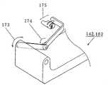
图16是示明图13、14中小臂操作臂142、162的概略结构图。FIG. 16 is a schematic structural view showing the small
图16中,173为基臂上下回转探测部,174为支臂上下回转探测部,175为操纵杆部。In Fig. 16, 173 is the up and down detection part of the base arm, 174 is the up and down rotation detection part of the support arm, and 175 is the joystick part.
图17为示明图15的操纵杆部172的概略结构图。FIG. 17 is a schematic configuration diagram showing the
图17中,176为手腕部旋转探测部,177为手腕上下回转探测部,178为基臂左右回转指令开关,179为手腕部左右回转指令开关180为手开闭指令开关。Among Fig. 17, 176 is the wrist rotation detection part, 177 is the wrist rotation detection part up and down, 178 is the left and right rotation command switch of the base arm, 179 is the wrist left and right
图18(a)、(b)为示明图16的操作杆部175的概略结构图。18( a ) and ( b ) are schematic configuration diagrams showing the operating
图18中,181为手腕部X回转探测部,182为手腕部Y转动探测部,183为基臂旋转探测部,184为基臂左右转动探测部,185为基臂伸缩指令开关,186为姆指开闭指令开关,187为中指开闭指令开关,188为食指开闭指令开关,189为手腕部回转探测部。In Fig. 18, 181 is the X rotation detection part of the wrist, 182 is the Y rotation detection part of the wrist, 183 is the base arm rotation detection part, 184 is the left and right rotation detection part of the base arm, 185 is the base arm expansion and contraction command switch, and 186 is the m Finger opening and closing command switch, 187 is the middle finger opening and closing command switch, 188 is the forefinger opening and closing command switch, and 189 is the wrist rotation detection part.
图19是示明图13、14中脚部操作盘143、163的概略结构图。Fig. 19 is a schematic configuration diagram showing the
图19中,190为开闭机器人装置2的照明装置(未图示)的照明指令开关,191为指令通信起动的通信起动指令开关,192为指令机器人装置全面停动的停动指令开关,193为指令左右前进的左右前进位移探测传感器,194为指令左右后退的左右后位移探测传感器,195为使上部机座左右回转的上部机座左右回转位移探测传感器,196为起动图3中发动机104的发动机起动指令开关,197为使排土板120c上下回转的排土板上下回转指令开关,198为使左右大臂操作臂固定或固定解除的大臂操作臂固定解除指令开关,199为使左右小臂操作臂142、162固定或固定解除的小臂操作臂的固定解除指令开关,200a为开关机器人装置2的扬声器18的扬声器指令开关,200b为开闭机器人装置2的微音器组17的微音器指令开关。In Fig. 19, 190 is a lighting command switch for opening and closing the lighting device (not shown) of the
通过操作图13~18所示大、小臂的操作臂141、142、161、162或开闭各开关,从机器人遥控装置1的远程指令装置4与乘车指令装置8,将各种控制数据(包括开、闭指令的控制数据)给予机器人装置2,控制机器人装置2的各种臂或手腕操作。此外,通过开闭图19的脚部操作盘143、163的各开关,或通过位移各位移探测器,可把作为开闭指令或位移指令作为控制数据给予机器人装置2,控制机器人装置的移动操作。这类操作臂的探测传感器或开关示明于表1、2与3。By operating the operating
表1示明左右小臂操作臂142、162,表2示明左右小臂操作臂142、162与大臂操作臂141、161,表3示明左右的大臂操作臂141、161和左右覆带26以及上部机座2a与排土板12c。Table 1 shows the left and right small arm operating arms 142,162, Table 2 shows the left and right small arm operating arms 142,162 and the large arm operating arms 141,161, and Table 3 shows the left and right large arm operating arms 141,161 and the left and right cover. The belt 26 and the
图20是示明图15、17中所示左大臂操作臂141、161。FIG. 20 is a diagram illustrating the left
图20中,基臂上下回转探测部171,支臂上下旋转探测部172,手腕部回转探测部176,手腕部上下回转指令开关177,基臂左右回转指令开关178,手腕部左右回转指令开关179与手开闭指令开关180与图15、17中的相同。In Fig. 20, the base arm rotates up and down the
图21为示明图16、18所示左小臂操作臂142、162的模式图。FIG. 21 is a schematic view showing the left
图21中的基臂上下回转探测部174,支臂上下回转探测部175,手腕部旋转探测部180、手腕部X回转探测部181、手腕部Y回转探测部182、基臂旋转指令开关183、基臂左右回转指令开关184、基臂伸缩指令开关185、姆指开闭指令开关186、中指开闭指令开关187以及食指指令开关188,都与图16、18中所示的相同。The base arm
图22是示明机器人装置2的大臂(大作业臂)120A的模式图。FIG. 22 is a schematic diagram showing a boom (big arm) 120A of the
图22中,201为基臂上下回转部,202为支臂上下转动部,203为手腕部左右转动部,204为手腕部上下转动部,205为手腕部旋转部,206为手开闭部。Among Fig. 22, 201 is the up and down rotation part of the base arm, 202 is the up and down rotation part of the support arm, 203 is the left and right rotation part of the wrist, 204 is the up and down rotation part of the wrist, 205 is the wrist rotation part, and 206 is a hand opening and closing part.
图23为示明机器人装置2的小臂(小作业臂)120B的模式图。FIG. 23 is a schematic diagram showing a small arm (small working arm) 120B of the
图23中,211为基臂上下转动部,212为基臂伸缩部,213为基臂旋转部,214为支臂上下回转部,215为手腕部X回转部,216为手腕部Y回转部,217为手腕部旋转部,218为姆指开闭部,219为中指开闭部,220为食指开闭部,221为基臂左右回转部。In Fig. 23, 211 is the base arm up and down rotation part, 212 is the base arm telescopic part, 213 is the base arm rotation part, 214 is the support arm up and down rotation part, 215 is the wrist X rotation part, 216 is the wrist Y rotation part, 217 is a wrist rotating part, 218 is a thumb opening and closing part, 219 is a middle finger opening and closing part, 220 is an index finger opening and closing part, and 221 is a base arm left and right turning part.
图24(a)、24(b)、24(c)说明固定图15、17中大臂操作臂141~161与图16、18中小臂操作臂142~162各探测部的位置的盘式摩擦片制动器,图24(b)示明致动器开动时,图24(c)示明致动器关闭时。Figures 24(a), 24(b), and 24(c) illustrate the disc friction that fixes the positions of the detection parts of the large arm operating arms 141-161 in Figures 15 and 17 and the detection parts of the small arm operating arms 142-162 in Figures 16 and 18 Plate brake, Figure 24(b) shows when the actuator is turned on, and Figure 24(c) shows when the actuator is closed.
图24中,222~223为机架,224为致动器,225为弹簧,226为致动器224驱动的从图面上看左右移动的圆板部。In FIG. 24 , 222 to 223 are racks, 224 is an actuator, 225 is a spring, and 226 is a circular plate portion driven by the actuator 224 to move left and right as seen in the drawing.
如图24(b)所示,致动器224开动时(励磁时),圆板部226离开机架,盘式摩擦片致动器断开(致动器无效状态)。如图24(c)所示,致动器22关闭时(非励磁时),圆板部226压迫制动器222,盘式摩擦片制动器闭合(制动器有效状态)。通过这样地开闭致动器224使盘式摩擦片制动器开闭,使各探测部的位置成为固定解除状态或固定状态。致动器224的开闭根据图19的固定解除指令开关198、199进行。As shown in FIG. 24( b ), when the actuator 224 is activated (excited), the disc portion 226 leaves the frame, and the disk friction plate actuator is disconnected (the actuator is in an invalid state). As shown in FIG. 24( c ), when the
下面用图25~29说明取上述结构的机器人遥控装置1与机器人装置2的操作。图25是示明机器人遥控装置1中发送作业的流程图。图26是示明机器人遥控装置1中接收作业(反力控制)的流程图,图27是示明机器人装置2的发送作业的流程图,图29~30是示明机器人装置2的接收作业的流程图。在此,图25、26示明CPU31的工作,图27~30示明CPU71的工作。Next, the operation of the robot
图25中,首先进行从图2所示的移动体通信装置35与拨号盘的连接,在PHS拨号盘连接完的信号通过移动体通信卡36,接口部32a通知CPU31后,CPU31判定可控,并将可控结果显示于显示装置部5(S1)。然后CPU31从远程指令装置4输入控制数据(包括旋转角度、回转角度、指令开关的开闭的控制数据)(S2),将各个控制数据格式化输出给移动体通信装置35(S3)。步骤S2、S3的操作重复到输出完所有的控制数据。In Fig. 25, at first carry out the connection from the
再用图26说明机器人遥控装置1的接收作业。Next, the receiving operation of the robot
图26中,图2所示的CPU31从移动体接收通信装置35读取接收数据(S11),基于此接收数据,进行远程指令装置4的操作臂141、142的反力控制(S12)。In FIG. 26, the
再用图27说明机器人装置2的发送操作。Next, referring to FIG. 27, the transmission operation of the
图27中,图3所示的CPU71从传感器组109输入传感器信号(S21),将此传感器信号作为格式化传感器数据输出给移动体通信装置75(S22)。步骤S21、S22的操作进行到所有传感器信号处理完(S23)。In FIG. 27, the
下面用图28~30说明机器人装置2的接收操作。Next, the receiving operation of the
图28中,首先图3所示的CPU71将从移动体通信装置75接收的数据作为各种控制数据读取(S31),进行操作臂控制(S32)与移动控制(S33)。In FIG. 28, first, the
再用图29说明步骤S32的操作臂控制。Next, the manipulation arm control in step S32 will be described with reference to FIG. 29 .
图29中,首先图3所示的CPU71判定是否为遥控(S41)。当判定为遥控时,由PHS接收控制数据(S42)。其次由CPU71判定有无操作禁止(S43),判定有无位置指示(S44),在有操作禁止或无位置指示时结束处理。在无操作禁止而有位置指示时,则判定偏差量为正或负(S45)。偏差量为正时,CPU71相对于马达用驱动装置93与油压伺服阀94,进行正的指示(马达正转,气缸正向移动)(S46);偏差量为负时则作相反的指示(马达反转,气缸负向移动)(S47)。其次判定有无速度指示(S48),当有速度指示时即指示与偏差量对应的速度(S49)。In FIG. 29, first, the
于步骤S41,当判定不是遥控时,CPU71起动乘车指令装置8(S50),判定有无操作禁止(S51),判定有无位置指示(S52)。在有操作禁止或无位置指示时,结束处理。在无操作禁止而有位置指示时,则进行偏差量为正或负的判定(S53)。偏差量为正时,CPU71相对于马达用驱动装置93与油压伺服阀94,进行正的指示(马达正转,气缸正向移动)(S54);偏差量为负时则作相反的指示(马达反转,气缸负向移动)(S55)。然后判定有无速度指示(S56),在有速度指示时,指示出与偏差量相对应的速度(S57)。In step S41, when it is determined that it is not a remote control, the
再用图30说明图28所示步骤33的移动控制。Referring again to FIG. 30, the movement control in
图30中,首先由图2所示CPU71判定是否为遥控(S61),当判定为遥控时,由DHS接收控制数据(S62)。其次CPU71判定有无移动禁止(S63)、有无移动指示(S64)。在有移动禁止时,报知此结果,结果处理(S70),在无移动指示时,立即结束处理。在无移动禁止而有移动指示时,随后判定是否前进(S65)。在前进时,CPU71相对马达用驱动装置93与油压伺服阀94,指示前进(S66);在非前进时,指示后退(S67)。然后判定有无速度指示(S68),在有速度指示时,输出指示速度(S69)。Among Fig. 30, at first by CPU71 shown in Fig. 2 judge whether it is remote control (S61), when judged as remote control, receive control data by DHS (S62). Next, the
于步骤S61,当判定为非遥控时,CPU71起动图1、3所示乘车指令装置8(S71),判定有无移动禁止(S72)、有无移动指示(S73)。在有移动禁止时,报知此结果,结果处理(S79),在没有移动指示时立即结束处理。对于没有移动禁止而有移动指示时,则判定是否前进(S74),在前进时,CPU71相对于马达用驱动装置93和油压伺服阀94指示前进(S75),不是前进时则指示后退(S76)。然后判定有无速度指示(S77),在有速度指示时,输出指示速度(S78)。In step S61, when it is judged as non-remote control,
根据上述本实施形式,机器人遥控装置1具有生成机器人装置2的控制数据的远程指令装置4、输入控制数据进行处理的第一计算机装置30、将控制数据发送给与公共线路网20连接的基地台19的第一移动体通信装置35,机器人装置2具有接收从与公共线路网20连接的基地台21发送来的控制数据的第二移动体通体通信装置75、处理控制数据以控制机械装置部10的第二计算机装置70,机械装置部10具有第二计算机装置70控制的1~2个大操作臂120A、1~2个小操作臂120B与移动系统,第二计算机装置70基于机器人装置2的控制数据控制1~2个大操作臂120A、1~2个小操作臂120B与移动系统,使机器人遥控装置1的控制数据通过第一移动体通信装置35传送,因而作为被控制体的机器人装置2至少是在日本不论配置于任何地方,也能控制此机器人装置2,同时由于机器人装置2具有1~2个大操作臂120A与1~2个小操作臂120B,就可由1~2个大操作臂120A进行重物撤除作业而由1~2个小操作臂120B进行灵巧的操作,可以获得能进行迅速救助活动的有利效果。According to the above-mentioned present embodiment, the robot
这1~2个大操作臂120A分别具有基臂121与125、支臂122与128、手腕部123与129、指部124与130,而由于有了这1~2个大操作臂120A和配置于这1~2个大操作臂120A内侧的1~2个小操作臂,配置于北侧的大操作臂120A可进行撤除重物等强力工作,而配置于内侧的1~2个小操作臂120B则能进行不需强力的灵巧工作,从而能可靠地进行迅速的救助活动。The 1 to 2
通过油压驱动1~2个大操作臂120A与移动系统,而通过电功率驱动1~2个小操作臂120B,于是油压驱动的大操作臂120A便能可靠地进行撤除重物的强力工作,而电功率驱动的1~2个小操作臂120B便可进行高精度的灵巧工作,从而得以高精度地和可靠地进行快捷的救助活动。1-2
通过使移动系统成为由油压驱动的履带2b机器人装置2即使是在凹凸不平的道路与陡峭的斜坡等难以行走的地面上,也能容易和高速的行动。By making the moving system the
机器人装置2具有由移动系统驱动的移动台以及在移动台上的机室,通过于机室内设置控制1~2个大操作臂120A和1~2个小操作臂120B以及移动系统的乘车指令装置8,由于乘车指令装置具有切换遥控控制和乘车控制的变换开关,则不仅是在远地,即使是在能搭乘的所谓机室附近场所,也易控制机器人装置。The
机械装置10具有拍摄对象物变换为图像信号的多个摄像机131-138以及将周围发生的声音变换为语言信号的麦克风,第二计算机装置70将图像信号与语言信号通过第二移动体通信装置75发送,机器人遥控装置1则接收第二移动体通信装置75的发送信号,将图像信号于监视器12上显示,将语言信号从扬声器14作为声音送出,这样即使在远地也能由图像与声音获知机器人装置2的状态,从而能正确和迅速地控制机器人装置。The
远程指令装置4具有用于控制大操作臂120A且自由旋转回转的大臂操作臂141和用于控制小操作臂120B且自由旋转回转的小臂操作臂142、配设于大臂操作臂141和小臂操作臂142上的多个传感器、执行开闭指令的多个指令开关,可基于多个传感器探测的旋转回转值以及多个指令开关的开闭生成机器人装置2的控制数据,若是操作上述大臂操作臂141与小臂操作臂142或是开闭指令开关,则通过此多个传感器与多个指令开关能生成机器人装置2的控制数据,从而能容易地控制机器人装置2。The
此外,乘车指令装置具有用于控制大操作臂120A且自由旋转回转的大臂操作臂161与和用于控制小操作臂120B且自由旋转回转的小臂操作臂162,设于大臂操作臂161和小臂操作臂162上的多个传感器,执行开闭指令的多个指令开关,可基于这多个传感器探测出的旋转回转值与多个指令开关的开闭而生成机器人装置2的控制数据,若是操作上述大臂操作臂161和小臂操作臂162或是开闭指令开关,则能通过多个传感器与多个指令开关生成机器人装置2的控制数据,从而易于控制机器人装置2。In addition, the ride instruction device has a large
再有,由于包括大臂操作臂固定解除指令开关198,用于开关致动器224来固定、解除固定大臂操作臂,和小臂操作臂固定解除指令开关199,用于开关致动器224来固定、解除固定小臂操作臂,自由旋转回转的大臂操作臂141、142和自由旋转回转的小臂操作臂161、162,通过具有致动器224驱动的圆极部的盘式摩擦片制动器等固定机构而成为固定状态或固定解除状态,于是容易使大臂与小臂等的操作臂141、142、161、162成为固定状态或固定解除状态,从而易于进行控制机器人装置的操作。Furthermore, since the large arm operating arm is fixed and released command switch 198 is used for switching actuator 224 to fix and unfix the large arm operating arm, and the small arm operating arm is fixed and released command switch 199 is used for switching actuator 224. To fix and unfix the small arm operating arm, the freely rotating large
如上所述,根据本发明第1方面的机器人遥控系统是具有遥控机器人的机器人遥控装置和根据遥控装置的数据控制的机器人装置的机器人遥控系统,其中:机器人遥控装置具有生成机器人装置的控制数据的远程指令装置、将控制数据输入进行处理的第一计算机装置、将控制数据发送到与公共线路网连接的基地台的第一移动体通信装置;机器人装置具有接收与公用线路网连接的基地台发送来的控制数据的第二移动体通信装置、处理控制数据控制机械装置部的第二计算机装置;机械装置部具有由第二计算机装置控制的1~2个大操作臂和1~2个小操作臂以及移动系统;1~2个小操作臂配置在1~2个大操作臂的内侧,第二计算机装置则根据机器人装置的控制数据控制1~2个大操作臂和1~2个小操作臂以及移动系统,这样,由于来自机器人遥控装置的控制数据是通过第一移动体通信装置传送,作为被控制体的机器人装置至少是即使配置于日本的任何地方,也能控制此机器人装置,同时由于机器人装置具有1~2个大操作臂和配置在1~2个大操作臂内侧的1~2个小操作臂,这配置在1~2个小操作臂外侧的1~2个大操作臂可用于进行撤除重物的工作,而这配置在1~2个大操作臂内侧的1~2个小操作臂则能进行灵巧的操作,故可获得能进行迅速的救助活动的有效效果。As described above, the robot remote control system according to the first aspect of the present invention is a robot remote control system having a robot remote control device for remote control of a robot and a robot device controlled based on data from the remote control device, wherein: the robot remote control device has a mechanism for generating control data of the robot device The remote command device, the first computer device that inputs the control data for processing, and the first mobile communication device that sends the control data to the base station connected to the public line network; The second mobile communication device that receives the control data, the second computer device that processes the control data and controls the mechanical device part; the mechanical device part has 1 to 2 large operating arms and 1 to 2 small operating arms controlled by the second computer device Arm and moving system; 1-2 small operating arms are arranged inside 1-2 large operating arms, and the second computer device controls 1-2 large operating arms and 1-2 small operating arms according to the control data of the robot device Arm and mobile system, in this way, since the control data from the robot remote control device is transmitted through the first mobile communication device, the robot device as the controlled object can control the robot device at least even if it is deployed anywhere in Japan, and at the same time Since the robot device has 1 to 2 large operating arms and 1 to 2 small operating arms arranged inside the 1 to 2 large operating arms, the 1 to 2 large operating arms arranged outside the 1 to 2 small operating arms It can be used to remove heavy objects, and the 1 to 2 small operating arms arranged inside the 1 to 2 large operating arms can perform dexterous operations, so the effective effect of rapid rescue activities can be obtained.
根据本发明第2方面的机器人遥控系统,它是在第1方面的遥控系统中,使此1~2个大操作臂和1~2个小操作臂分别具有基臂、支臂、手腕部与指部,由于具有该1~2个大操作臂和该1~2个大操作臂内配置的1~2个小操作臂,配置于外侧的大操作臂可进行撤除重物工作的强有力的工作,而配置于内侧的1~2个小操作臂则可进行不需强力的灵巧操作,就能获得可靠地进行迅速的救助活动的有利效果。According to the robot remote control system of the second aspect of the present invention, in the remote control system of the first aspect, the 1 to 2 large operating arms and the 1 to 2 small operating arms have base arms, support arms, wrists and Fingers, since there are 1 to 2 large operating arms and 1 to 2 small operating arms arranged in the 1 to 2 large operating arms, the large operating arm arranged on the outside can be used to remove heavy objects. work, and the 1-2 small operating arms arranged on the inner side can perform dexterous operations without strong force, and can obtain the favorable effect of reliably carrying out rapid rescue activities.
根据本发明第3方面的机器人遥控系统,它是在第1或2方面的机器人遥控系统中,由油压驱动1~2个大操作臂和移动系统而由电功率驱动1~2个小操作臂,由于油压驱动的大操作臂能可靠地进行撤除重物工作的强有力的工作,而电功率驱动的1~2个小操作臂能进行高精度的灵巧工作,就能获得能高精度地和可靠地进行迅速的救助活动的有利效果。According to the robot remote control system of the third aspect of the present invention, in the robot remote control system of the first or second aspect, 1 to 2 large operating arms and the moving system are driven by oil pressure, and 1 to 2 small operating arms are driven by electric power Because the large operating arm driven by oil pressure can reliably perform powerful work for removing heavy objects, and the 1 to 2 small operating arms driven by electric power can perform dexterous work with high precision, it can obtain high-precision and dexterous work. Favorable effects of reliable and prompt salvage operations.
根据本发明第4方面的机器人遥控系统,它是在第1~3方面中任一方面所述的机器人遥控系统中,使该移动系统为油压驱动的辊,因此,机器人装置即使在凹凸不平的道路和陡峭的坡地等难以行走的地形上,也能用来进行容易和高速的移动的有利效果。According to the robot remote control system according to the fourth aspect of the present invention, in the robot remote control system according to any one of the first to third aspects, the moving system is a roller driven by oil pressure, so that the robot can be moved even if it is uneven It can also be used for easy and high-speed movement on difficult-to-walk terrain such as roads and steep slopes.
根据本发明第5方面的机器人遥控系统,它是在第1~4方面中任一方面所述的机器人遥控系统中,使机器人装置具有由移动系统驱动的移动台以及在移动台上的机室,而在机室内则具有控制这1~2个大操作臂和1~2个小操作臂以及移动系统的乘车用指令装置,该乘车指令装置具有切换遥控控制和乘车控制的遥控乘车变换开关,由此,只切换遥控乘车变换开关,不仅是远地,即使在能搭乘的所谓机室附近处,也能获得容易地控制机器人装置。According to the robot remote control system of the fifth aspect of the present invention, in the robot remote control system described in any one of the first to fourth aspects, the robot device has a mobile platform driven by the mobile system and a machine room on the mobile platform. , and in the engine room, there is a command device for controlling the 1~2 large operating arms and 1~2 small operating arms and the moving system. The car changing switch, thus, only switches the remote control riding changing switch, not only in a remote place, but also in the vicinity of the so-called machine room where the robot can be boarded, and it is easy to control the robot device.
根据本发明第6方面的机器人遥控系统,它是在第1~5方面中任一方面所述的机器人遥控系统中,使机械装置部具有将对象物拍摄而变换为图像信号的多个摄像机、将周围发生的声音变换为音频信号的多个麦克风;第二计算机装置通过第二移动体通信装置发送图像信号与音频信号;机器人遥控装置接收第二移动体通信装置的发送信号,将图像信号于监视器上显示,将音频信号从扬声器作为声音发送出,由此,即使在远地,由于能通过图像和声音了解机器人装置的状态,就可能获得正确和迅速地控制机器人装置的有利效果。According to the robot remote control system according to the sixth aspect of the present invention, in the robot remote control system according to any one of the first to fifth aspects, the mechanical device part has a plurality of cameras for capturing images of objects and converting them into image signals, A plurality of microphones that convert the surrounding sounds into audio signals; the second computer device sends image signals and audio signals through the second mobile communication device; Displayed on the monitor, the audio signal is sent out as sound from the speaker, thereby, even in a remote place, since the state of the robot device can be understood through the image and sound, it is possible to obtain an advantageous effect of controlling the robot device correctly and quickly.
根据本发明第7方面的机器人遥控系统,它是在第1~6方面中任一方面所述的机器人遥控系统中,上述远程指令装置包括有:控制上述大操作臂自由旋转回转的大臂操作臂、控制上述小操作臂自由旋转回转的小臂操作臂、设于上述大操作臂与上述小操作臂上的多个传感器、执行开闭指令的多个指令开关,且根据多个传感器探测出的旋转转动值与多个指令开关的开闭生成机器人装置的控制数据,由此,若是操作大臂操作臂和小臂操作臂或是开闭指令开关,则可借助多个传感器与多个指令开关生成机器人装置的控制数据,于是能获得容易地控制机器人装置的有利效果。According to the robot remote control system according to the seventh aspect of the present invention, in the robot remote control system described in any one of the first to sixth aspects, the above-mentioned remote command device includes: a large arm operation for controlling the free rotation of the above-mentioned large operating arm arm, a small arm operating arm that controls the free rotation of the small operating arm, a plurality of sensors arranged on the above-mentioned large operating arm and the above-mentioned small operating arm, and a plurality of command switches that perform opening and closing commands, and detect The rotation value of the rotation and the opening and closing of multiple command switches generate the control data of the robot device. Therefore, if the boom operating arm and the small arm operating arm or the opening and closing command switches are operated, multiple sensors and multiple commands can be used to control data. The switch generates control data of the robot, and thus the advantageous effect of easily controlling the robot can be obtained.
根据本发明第8方面的机器人遥控系统,它是在第5~7方面中任一方面所述的机器人遥控系统中,上述乘车指令装置包括有:控制上述大操作臂自由旋转回转的大臂操作臂、控制上述小操作臂自由旋转回转的小臂操作臂、设于上述大操作臂与上述小操作臂上的多个传感器、执行开闭指令的多个指令开关,且根据此多个传感器探测出的旋转回转的值与多个指令开关的开闭,生成机器人装置的控制数据,由此,若是操作大臂操作臂和小臂操作臂或是开闭指令开关,则可借助多个传感器与多个指令开关生成机器人装置的控制数据,于是能获得容易地控制机器人装置的有利效果。According to the robot remote control system of the eighth aspect of the present invention, it is in the robot remote control system described in any one of the fifth to seventh aspects, the above-mentioned riding command device includes: a large arm that controls the free rotation of the above-mentioned large operating arm The operating arm, the small arm operating arm that controls the free rotation of the small operating arm, the multiple sensors provided on the large operating arm and the small operating arm, and the multiple command switches that execute the opening and closing commands, and according to the multiple sensors The detected rotation value and the opening and closing of multiple command switches generate the control data of the robot device. Therefore, when operating the boom manipulator arm and the small arm manipulator arm or the opening and closing command switch, multiple sensors can be used. The control data of the robot device is generated with a plurality of command switches, and thus the advantageous effect of easily controlling the robot device can be obtained.
根据本发明第9方面的机器人遥控系统,它是在第7或8方面的机器人遥控系统中,使自由旋转转动的操作臂通过具有由致动器驱动的圆盘式摩擦片制动器的固定机构,取固定状态或固定解除状态。由此,大臂与小臂的操作臂易取固定状态或固定解除状态,于是能获得可方便地进行机器人装置控制的操作的有利效果。According to the robot remote control system of the ninth aspect of the present invention, in the robot remote control system of the seventh or eighth aspect, the operating arm that is freely rotatable passes through a fixing mechanism having a disk type friction brake driven by an actuator, Take the fixed state or the fixed unfixed state. Thereby, the operating arms of the large arm and the small arm can easily take the fixed state or the fixed release state, and thus an advantageous effect that the operation of the robot device control can be easily performed can be obtained.
表1Table 1
表2Table 2

表3table 3

Claims (1)
Translated fromChineseApplications Claiming Priority (1)
| Application Number | Priority Date | Filing Date | Title |
|---|---|---|---|
| PCT/JP2003/007451WO2004110702A1 (en) | 2001-11-30 | 2003-06-12 | Robot remote control system |
Publications (2)
| Publication Number | Publication Date |
|---|---|
| CN1771113A CN1771113A (en) | 2006-05-10 |
| CN100400244Ctrue CN100400244C (en) | 2008-07-09 |
Family
ID=36751897
Family Applications (1)
| Application Number | Title | Priority Date | Filing Date |
|---|---|---|---|
| CNB038261146AExpired - LifetimeCN100400244C (en) | 2003-06-12 | 2003-06-12 | Robot remote control system |
Country Status (4)
| Country | Link |
|---|---|
| US (1) | US20060212168A1 (en) |
| EP (1) | EP1632317A4 (en) |
| CN (1) | CN100400244C (en) |
| WO (1) | WO2004110702A1 (en) |
Families Citing this family (24)
| Publication number | Priority date | Publication date | Assignee | Title |
|---|---|---|---|---|
| WO2007029800A1 (en)* | 2005-09-09 | 2007-03-15 | Kagoshima University | Remote-controlled mobile machine using flexible shafts |
| CN100410030C (en)* | 2006-07-07 | 2008-08-13 | 中国科学院力学研究所 | A Path Planning Method for Robot Obstacle Avoidance Based on Virtual Scene |
| EP1914353A3 (en)* | 2006-10-19 | 2011-04-20 | Hitachi Construction Machinery Co., Ltd. | Construction machine |
| ES2343558B2 (en)* | 2007-12-13 | 2011-08-17 | Universidad De Malaga | ROBOTIC SYSTEM WITH ALL-GROUND CAPACITY AND MULTIPLE MANIPULATOR ARM, AND SEPARABLE CONTROL AND SENSORY ELEMENTS AND AT THE SAME FUNCTIONAL TIME. |
| KR101479234B1 (en)* | 2008-09-04 | 2015-01-06 | 삼성전자 주식회사 | Robot and its control method |
| US8415909B2 (en)* | 2010-04-22 | 2013-04-09 | General Electric Company | Power control on a multi-motion electric drive system |
| KR101194576B1 (en)* | 2010-12-16 | 2012-10-25 | 삼성중공업 주식회사 | Wind turbine assembly and management robot and wind turbine including the same |
| CN103217910A (en)* | 2012-01-18 | 2013-07-24 | 苏州宝时得电动工具有限公司 | Robot and control system thereof |
| CN102914284B (en)* | 2012-10-19 | 2015-07-08 | 中铁隧道集团有限公司 | Real-time measurement system for work position of operation arm and measurement method thereof |
| CN103147789B (en)* | 2013-03-07 | 2015-03-25 | 中国矿业大学 | System and method for controlling underground coal mine rescue robot |
| US9621771B2 (en)* | 2013-03-14 | 2017-04-11 | Pelco, Inc. | System and method for imaging utility panel elements |
| US9292015B2 (en)* | 2013-05-23 | 2016-03-22 | Fluor Technologies Corporation | Universal construction robotics interface |
| CN103522303B (en)* | 2013-10-30 | 2015-10-28 | 重庆科技学院 | Explosive ordnance disposal device of explosive ordnance disposal robot and control system thereof and control method |
| CN103552084B (en)* | 2013-10-30 | 2015-12-02 | 重庆科技学院 | EOD robot |
| CN106313038B (en)* | 2015-06-30 | 2019-01-29 | 芋头科技(杭州)有限公司 | A kind of real-time control debugging system and adjustment method |
| US9827678B1 (en)* | 2016-05-16 | 2017-11-28 | X Development Llc | Kinematic design for robotic arm |
| US9827677B1 (en)* | 2016-05-16 | 2017-11-28 | X Development Llc | Robotic device with coordinated sweeping tool and shovel tool |
| CN106956264A (en)* | 2017-05-18 | 2017-07-18 | 科大智能电气技术有限公司 | A kind of long-distance remote control system of electric inspection process robot |
| CN107671852A (en)* | 2017-11-12 | 2018-02-09 | 高飞 | A kind of novel robot structure |
| TWI677314B (en) | 2017-12-29 | 2019-11-21 | 技嘉科技股份有限公司 | Moving devices and controlling methods, remote controlling systems and computer products thereof |
| CN108406810A (en)* | 2018-03-27 | 2018-08-17 | 南京中高知识产权股份有限公司 | A kind of robot system suitable for remote control |
| CN109407563A (en)* | 2018-12-26 | 2019-03-01 | 北京百度网讯科技有限公司 | The control system and its control method of unmanned engineering machinery |
| US11633848B2 (en) | 2019-07-31 | 2023-04-25 | X Development Llc | Independent pan of coaxial robotic arm and perception housing |
| CN113015381A (en)* | 2021-03-12 | 2021-06-22 | 黄河科技学院 | Law book file library environment monitoring device |
Citations (5)
| Publication number | Priority date | Publication date | Assignee | Title |
|---|---|---|---|---|
| JPH05138566A (en)* | 1991-11-25 | 1993-06-01 | Tokyo Electric Power Co Inc:The | Robot for overhead power distribution work |
| JPH0614191U (en)* | 1992-05-21 | 1994-02-22 | 株式会社アイチコーポレーション | Aerial work vehicle |
| JPH10277976A (en)* | 1997-04-07 | 1998-10-20 | Fujita Corp | Remote control system |
| US6232735B1 (en)* | 1998-11-24 | 2001-05-15 | Thames Co., Ltd. | Robot remote control system and robot image remote control processing system |
| JP2001269885A (en)* | 2000-01-18 | 2001-10-02 | Temusu:Kk | Robot remote control device and robot device |
Family Cites Families (8)
| Publication number | Priority date | Publication date | Assignee | Title |
|---|---|---|---|---|
| US4252360A (en)* | 1979-06-12 | 1981-02-24 | Gallaher Jr John K | Mechanical handling apparatus |
| FR2482508A1 (en)* | 1980-05-14 | 1981-11-20 | Commissariat Energie Atomique | MANIPULATOR AND MOTORIZED ORIENTATION BRACKET FOR SUCH A MANIPULATOR |
| US5657429A (en)* | 1992-08-10 | 1997-08-12 | Computer Motion, Inc. | Automated endoscope system optimal positioning |
| JPH09109069A (en)* | 1995-10-13 | 1997-04-28 | Gen Sugano | Powered intelligent method and unit |
| US5777267A (en)* | 1996-06-28 | 1998-07-07 | Abb Flexible Automation, Inc. | Harness assembly to provide signals to end effector |
| JPH10277970A (en)* | 1997-04-07 | 1998-10-20 | Fujita Corp | Remote control system |
| EP1010820A4 (en)* | 1997-07-11 | 2002-07-31 | Komatsu Mfg Co Ltd | Work machine |
| US6951535B2 (en)* | 2002-01-16 | 2005-10-04 | Intuitive Surgical, Inc. | Tele-medicine system that transmits an entire state of a subsystem |
- 2003
- 2003-06-12CNCNB038261146Apatent/CN100400244C/ennot_activeExpired - Lifetime
- 2003-06-12EPEP03817256Apatent/EP1632317A4/ennot_activeWithdrawn
- 2003-06-12WOPCT/JP2003/007451patent/WO2004110702A1/enactiveApplication Filing
- 2003-06-12USUS10/550,258patent/US20060212168A1/ennot_activeAbandoned
Patent Citations (5)
| Publication number | Priority date | Publication date | Assignee | Title |
|---|---|---|---|---|
| JPH05138566A (en)* | 1991-11-25 | 1993-06-01 | Tokyo Electric Power Co Inc:The | Robot for overhead power distribution work |
| JPH0614191U (en)* | 1992-05-21 | 1994-02-22 | 株式会社アイチコーポレーション | Aerial work vehicle |
| JPH10277976A (en)* | 1997-04-07 | 1998-10-20 | Fujita Corp | Remote control system |
| US6232735B1 (en)* | 1998-11-24 | 2001-05-15 | Thames Co., Ltd. | Robot remote control system and robot image remote control processing system |
| JP2001269885A (en)* | 2000-01-18 | 2001-10-02 | Temusu:Kk | Robot remote control device and robot device |
Also Published As
| Publication number | Publication date |
|---|---|
| EP1632317A1 (en) | 2006-03-08 |
| US20060212168A1 (en) | 2006-09-21 |
| WO2004110702A1 (en) | 2004-12-23 |
| CN1771113A (en) | 2006-05-10 |
| EP1632317A4 (en) | 2009-04-08 |
Similar Documents
| Publication | Publication Date | Title |
|---|---|---|
| CN100400244C (en) | Robot remote control system | |
| US11717969B1 (en) | Cooperative high-capacity and high-dexterity manipulators | |
| JP4658892B2 (en) | Mobile robot, mobile robot control device, mobile robot control method, and mobile robot control program | |
| US11660750B1 (en) | Autonomous and semi-autonomous control of aerial robotic systems | |
| CN103112515B (en) | Wheel leg combined type robot | |
| CN108406726A (en) | A kind of wheel type movable machine explosive-removal robot | |
| CN107719673A (en) | Long-range control method and terminal | |
| CN110978004A (en) | An autonomous distribution network live working robot, system and method | |
| CN109071186A (en) | Construction machinery | |
| CN108177149A (en) | Movable mechanical arm control system and method based on MR and motion planning technology | |
| CN105857593A (en) | A four-rotor multi-purpose flying robot | |
| CN110076796A (en) | A variable topology multi-joint collaborative follower robot | |
| KR20190136962A (en) | Force-sense visualization apparatus, robot, and force-sense visualization program | |
| CN210551257U (en) | Crawler-type explosive-handling robot | |
| CN115958575A (en) | Humanoid dexterous operation mobile robot | |
| CN114872050A (en) | Control method and control system for double-arm crawler-type mobile operation robot | |
| CN208557467U (en) | Multifunctional mobile robot for cable trench inspection operation | |
| CN119427324B (en) | A force feedback exoskeleton and humanoid robot imitation learning method | |
| JP2003170375A (en) | Robot remote control system | |
| CN115464636A (en) | Remote operation control system and control method for substation robot to hang/pick ground wire | |
| CN104018676B (en) | A kind of engineering machinery and arm support control system and method | |
| CN103286783B (en) | The movement velocity control method of rope traction cameras people | |
| CN117885110A (en) | A humanoid robot for high-altitude operations | |
| TWM370479U (en) | Multi-function robot | |
| JP4945759B2 (en) | Moving device between walls |
Legal Events
| Date | Code | Title | Description |
|---|---|---|---|
| C06 | Publication | ||
| PB01 | Publication | ||
| C10 | Entry into substantive examination | ||
| SE01 | Entry into force of request for substantive examination | ||
| C14 | Grant of patent or utility model | ||
| GR01 | Patent grant | ||
| CX01 | Expiry of patent term | ||
| CX01 | Expiry of patent term | Granted publication date:20080709 |