CN100399802C - Vehicle imaging device and method - Google Patents
Vehicle imaging device and methodDownload PDFInfo
- Publication number
- CN100399802C CN100399802CCNB200510120109XACN200510120109ACN100399802CCN 100399802 CCN100399802 CCN 100399802CCN B200510120109X ACNB200510120109X ACN B200510120109XACN 200510120109 ACN200510120109 ACN 200510120109ACN 100399802 CCN100399802 CCN 100399802C
- Authority
- CN
- China
- Prior art keywords
- image
- state
- vehicle
- main control
- power supply
- Prior art date
- Legal status (The legal status is an assumption and is not a legal conclusion. Google has not performed a legal analysis and makes no representation as to the accuracy of the status listed.)
- Expired - Fee Related
Links
- 238000003384imaging methodMethods0.000titleclaimsabstractdescription28
- 238000000034methodMethods0.000titleclaimsdescription27
- 238000012545processingMethods0.000claimsabstractdescription47
- 238000001514detection methodMethods0.000claimsabstractdescription25
- 230000007958sleepEffects0.000claimsabstractdescription22
- 238000013459approachMethods0.000claimsabstractdescription15
- 230000008569processEffects0.000claimsdescription19
- 230000007246mechanismEffects0.000claimsdescription6
- 230000006399behaviorEffects0.000claimsdescription4
- 238000012544monitoring processMethods0.000claimsdescription2
- 230000015654memoryEffects0.000description48
- 238000004891communicationMethods0.000description13
- 230000003936working memoryEffects0.000description6
- 10210003628525-hydroxyvitamin D-1 alpha hydroxylase, mitochondrialHuman genes0.000description4
- 101000875403Homo sapiens 25-hydroxyvitamin D-1 alpha hydroxylase, mitochondrialProteins0.000description4
- 238000010586diagramMethods0.000description4
- 239000002131composite materialSubstances0.000description3
- 238000006243chemical reactionMethods0.000description2
- 230000006870functionEffects0.000description2
- 230000001360synchronised effectEffects0.000description2
- 238000012546transferMethods0.000description2
- 230000002159abnormal effectEffects0.000description1
- 230000005540biological transmissionEffects0.000description1
- 230000000903blocking effectEffects0.000description1
- 238000013144data compressionMethods0.000description1
- 230000005059dormancyEffects0.000description1
- 239000011521glassSubstances0.000description1
- 230000020169heat generationEffects0.000description1
- 230000004044responseEffects0.000description1
Images


Classifications
- B—PERFORMING OPERATIONS; TRANSPORTING
- B60—VEHICLES IN GENERAL
- B60R—VEHICLES, VEHICLE FITTINGS, OR VEHICLE PARTS, NOT OTHERWISE PROVIDED FOR
- B60R25/00—Fittings or systems for preventing or indicating unauthorised use or theft of vehicles
- B60R25/10—Fittings or systems for preventing or indicating unauthorised use or theft of vehicles actuating a signalling device
- B60R25/1004—Alarm systems characterised by the type of sensor, e.g. current sensing means
- B—PERFORMING OPERATIONS; TRANSPORTING
- B60—VEHICLES IN GENERAL
- B60R—VEHICLES, VEHICLE FITTINGS, OR VEHICLE PARTS, NOT OTHERWISE PROVIDED FOR
- B60R11/00—Arrangements for holding or mounting articles, not otherwise provided for
- B60R11/04—Mounting of cameras operative during drive; Arrangement of controls thereof relative to the vehicle
- B—PERFORMING OPERATIONS; TRANSPORTING
- B60—VEHICLES IN GENERAL
- B60R—VEHICLES, VEHICLE FITTINGS, OR VEHICLE PARTS, NOT OTHERWISE PROVIDED FOR
- B60R25/00—Fittings or systems for preventing or indicating unauthorised use or theft of vehicles
- B60R25/10—Fittings or systems for preventing or indicating unauthorised use or theft of vehicles actuating a signalling device
- B60R25/102—Fittings or systems for preventing or indicating unauthorised use or theft of vehicles actuating a signalling device a signal being sent to a remote location, e.g. a radio signal being transmitted to a police station, a security company or the owner
- B—PERFORMING OPERATIONS; TRANSPORTING
- B60—VEHICLES IN GENERAL
- B60R—VEHICLES, VEHICLE FITTINGS, OR VEHICLE PARTS, NOT OTHERWISE PROVIDED FOR
- B60R25/00—Fittings or systems for preventing or indicating unauthorised use or theft of vehicles
- B60R25/30—Detection related to theft or to other events relevant to anti-theft systems
- B60R25/305—Detection related to theft or to other events relevant to anti-theft systems using a camera
- G—PHYSICS
- G08—SIGNALLING
- G08B—SIGNALLING OR CALLING SYSTEMS; ORDER TELEGRAPHS; ALARM SYSTEMS
- G08B13/00—Burglar, theft or intruder alarms
- G08B13/18—Actuation by interference with heat, light, or radiation of shorter wavelength; Actuation by intruding sources of heat, light, or radiation of shorter wavelength
- G08B13/189—Actuation by interference with heat, light, or radiation of shorter wavelength; Actuation by intruding sources of heat, light, or radiation of shorter wavelength using passive radiation detection systems
- G08B13/194—Actuation by interference with heat, light, or radiation of shorter wavelength; Actuation by intruding sources of heat, light, or radiation of shorter wavelength using passive radiation detection systems using image scanning and comparing systems
- G08B13/196—Actuation by interference with heat, light, or radiation of shorter wavelength; Actuation by intruding sources of heat, light, or radiation of shorter wavelength using passive radiation detection systems using image scanning and comparing systems using television cameras
- B—PERFORMING OPERATIONS; TRANSPORTING
- B60—VEHICLES IN GENERAL
- B60R—VEHICLES, VEHICLE FITTINGS, OR VEHICLE PARTS, NOT OTHERWISE PROVIDED FOR
- B60R2325/00—Indexing scheme relating to vehicle anti-theft devices
- B60R2325/30—Vehicles applying the vehicle anti-theft devices
Landscapes
- Engineering & Computer Science (AREA)
- Mechanical Engineering (AREA)
- Physics & Mathematics (AREA)
- General Physics & Mathematics (AREA)
- Closed-Circuit Television Systems (AREA)
- Burglar Alarm Systems (AREA)
- Studio Devices (AREA)
- Alarm Systems (AREA)
Abstract
Description
Translated fromChinese技术领域technical field
本发明涉及在可疑者等侵入车辆内之际有效的车辆用图像摄影装置和方法。The present invention relates to a vehicle imaging device and method that are effective when a suspicious person or the like invades a vehicle.
背景技术Background technique
历来,在停车场或路上停车中的车辆有时被盗,或可疑者在车内捣乱。Historically, vehicles parked in parking lots or on the road are sometimes stolen, or suspicious persons make trouble in the vehicle.
因此,JP2001-338378A提出了备有检测可疑者向车辆室内的侵入的传感器,配置于车辆室内的规定位置的摄影装置,连接于无线电话装置而进行通信工作的无线电话控制装置,室内侵入通知用的输出语音信息的语音响应装置,输入并储存从上述摄影装置所输出的影像信号的影像存储装置,显示储存的影像信号的图像的画面显示装置,以及用来操作输入侵入者是该车辆的所有者的车主开关的车辆用室内侵入通知和摄影记录装置。Therefore, JP2001-338378A proposes to be equipped with a sensor for detecting the intrusion of a suspicious person into the vehicle interior, a photographing device arranged at a predetermined position in the vehicle interior, a radiotelephone control device connected to a radiotelephone device for communication, and an indoor intrusion notification. A voice response device for outputting voice information, an image storage device for inputting and storing the video signal output from the above-mentioned photographing device, a screen display device for displaying the image of the stored video signal, and a device for operating and inputting whether the intruder is the owner of the vehicle The indoor intrusion notification and photographic recording device for vehicles switched by the owner of the vehicle.
在这种装置中,上述传感器一输出检测信号,从该检测信号的输出时刻起规定时间内上述车主开关未被接通操作时,开始上述摄影装置的摄影工作,开始从上述摄影装置所输出的上述影像信号的储存,并且向预先在上述无线电话装置中所登录的通知目的号码呼叫。该通知目的号码一响应,就输出语音信息,经由上述无线电话装置向上述通知目的号码通知。In this kind of device, once the above-mentioned sensor outputs a detection signal, when the above-mentioned vehicle owner switch is not turned on and operated within a predetermined period of time from the output of the detection signal, the photographing operation of the above-mentioned photographing device is started, and the image output from the above-mentioned photographing device is started. The image signal is stored, and a call is made to the notification destination number registered in advance in the wireless telephone device. When the notification destination number responds, voice information is output to notify the notification destination number via the wireless telephone device.
这样一来,在车辆上搭载摄像机等摄影装置等的场合,电源从电池供给。虽然摄影装置和图像处理电路的消耗电流很大,但是为了监视侵入和被盗,在车辆停车时有必要向其供给电力使之工作。但是,如果使车辆长时间停车,则因摄影装置等的工作大量地消耗电力有时引起电池用尽。In this way, when an imaging device such as a video camera is mounted on a vehicle, power is supplied from the battery. Although the current consumption of the imaging device and the image processing circuit is large, in order to monitor intrusion and theft, it is necessary to supply power to them to operate when the vehicle is parked. However, if the vehicle is parked for a long period of time, the battery may be exhausted due to a large amount of power consumption due to the operation of the imaging device or the like.
因此,JP2002-308054A提出了备有进行由摄像机所摄影的图像数据的处理的摄像机ECU,基于图像数据的内容而进行规定的处理的主控制部(网关装置,安全性ECU),以及经由ACC继电器把电源供给到摄像机和摄像机ECU的图像系统电源路径,在可疑者相对于车辆的侵入被检测到时把图像系统电源路径从切断切换到接通的装置。如果采用这种装置,则由于未检测到可疑者相对于车辆的侵入时就不供给向摄像机和摄像机ECU的电源,所以可以降低消耗电流,电池的负载也降低而能够防止电池用尽。但是,摄像机等摄影装置因为自动增益控制故从供给电源到成为能够摄影起需要一定时间的迟延(1~2秒)。由此,如果是在可疑者相对于车辆的侵入时接通图像系统电源路径的方法,则存在着失去适当的摄影时机的可能性。Therefore, JP2002-308054A proposes a camera ECU for processing image data captured by the camera, a main control unit (gateway device, safety ECU) for performing predetermined processing based on the content of the image data, and an ACC relay A device that supplies power to the video system power path of the camera and the camera ECU, and switches the power path of the video system from off to on when a suspicious person's intrusion into the vehicle is detected. According to such a device, power is not supplied to the camera and the camera ECU when the intrusion of a suspicious person into the vehicle is not detected, so the current consumption can be reduced, and the load on the battery can be reduced to prevent the battery from being exhausted. However, an imaging device such as a video camera requires a certain time delay (1 to 2 seconds) from when power is supplied to when imaging becomes possible due to automatic gain control. Therefore, if a method of turning on the power supply path of the imaging system is used when a suspicious person enters the vehicle, there is a possibility that an appropriate shooting timing may be missed.
发明内容Contents of the invention
本发明的课题在于提供一种可以既以低消耗电流工作,又以最佳的摄影时机摄影图像的车辆用图像摄影装置和方法。An object of the present invention is to provide a vehicle imaging device and method capable of capturing an image at an optimal timing while operating with low current consumption.
本发明提供一种搭载于车辆上的车辆用图像摄影装置,备有:图像处理部,进行由包含摄像机的图像录像装置所录像的图像数据的处理;主控制部,基于前述图像数据的内容进行规定的处理;主控制系统电源,将电源供给到前述主控制部;图像系统电源,与前述主控制系统电源分别设置,将电源供给到前述图像录像装置和前述图像处理部;接近检测机构,检测人体相对于前述车辆的接近;侵入检测机构,检测人体相对于前述车辆的侵入;判定机构,在由前述接近检测机构检测到人体相对于前述车辆的接近时判定成使前述图像系统电源成为接通状态的条件成立;前述主控制部控制前述图像系统电源的通/断状态,在由前述判定机构判定成使前述图像系统电源成为接通状态的条件成立时使前述图像系统电源成为接通状态;在前述图像系统电源为接通状态、且由前述侵入检测机构检测到人体相对于前述车辆的侵入时,上述主控制部发出图像摄影触发信号,使前述图像录像装置和前述图像处理部从作为低电力消耗状态的休眠状态成为第1规定时间唤醒状态;前述图像录像装置成为唤醒状态时对图像进行摄影。The present invention provides a vehicle image capturing device mounted on a vehicle, comprising: an image processing unit that processes image data recorded by an image recording device including a camera; and a main control unit that processes image data based on the content of the image data. The prescribed processing: the main control system power supply supplies power to the aforementioned main control unit; the imaging system power supply is provided separately from the aforementioned main control system power supply, and supplies power to the aforementioned image recording device and the aforementioned image processing unit; the proximity detection mechanism detects Approach of the human body to the vehicle; intrusion detection means for detecting intrusion of the human body with respect to the vehicle; determination means for determining to turn on the power supply of the image system when the approach detection means detects the approach of the human body to the vehicle The condition of the state is satisfied; the main control unit controls the on/off state of the image system power supply, and turns the image system power supply into the on state when it is determined by the determination means that the condition for turning the image system power supply into the on state is satisfied; When the power of the imaging system is turned on and the intrusion detection mechanism detects the intrusion of the human body into the vehicle, the main control unit sends an image shooting trigger signal to make the image recording device and the image processing unit operate as low The sleep state of the power consumption state becomes the wake-up state for a first predetermined time; the image recording device captures an image when it is in the wake-up state.
本发明还提供一种车辆用图像摄影方法,其监视有无相对于车辆的侵入前的规定的行为;如果检测到前述规定的行为,则使包含图像摄影摄像机的图像系统的电源成为接通状态;监视有无人体相对于车辆的侵入,在前述接通状态下检测到前述人体的侵入时,发出图像摄影触发信号,使前述图像摄影摄像机和图像处理部在规定时间中从作为低电力消耗状态的休眠状态成为唤醒状态,用前述图像摄影摄像机对图像进行摄影。The present invention also provides an image capturing method for a vehicle, which monitors whether there is a predetermined behavior before intrusion into the vehicle; if the predetermined behavior is detected, the power of the image system including the image capturing camera is turned on. ; Monitor whether there is human body intrusion relative to the vehicle, and when the aforementioned human body intrusion is detected in the aforementioned ON state, an image shooting trigger signal is sent, so that the aforementioned image shooting camera and the image processing unit are in a low power consumption state within a predetermined period of time. The dormant state becomes the wake-up state, and the image is captured by the aforementioned image capturing camera.
车辆用图像摄影装置和方法在人体相对于车辆的接近被检测到时使图像系统电源成为接通状态,在图像系统电源成为接通状态、且人体相对于车辆的侵入被检测到时使图像录像装置和图像处理部从作为低电力消耗状态的休眠状态成为第1规定时间唤醒状态。结果,图像录像装置在从休眠状态切换到规定时间唤醒状态的时刻图像系统电源已经成为接通状态,在人体相对于车辆的侵入时可以没有迟延地在最佳的摄影时机对图像进行摄影。Vehicle imaging device and method for turning on power of an image system when approach of a human body to a vehicle is detected, and recording an image when the power of the image system is turned on and intrusion of a human body into a vehicle is detected The device and the image processing unit are turned from the sleep state which is a low power consumption state to the wake-up state for the first predetermined time. As a result, the power supply of the imaging system is already on when the image recording device switches from the sleep state to the wake-up state at a predetermined time, and images can be captured at an optimal timing without delay when a human body enters the vehicle.
主控制部在判定成使前述图像系统电源成为接通状态的条件成立时,使图像系统电源的状态从切断状态成为接通状态,并且发出图像摄影触发信号,使图像录像装置和图像处理部成为第2规定时间唤醒状态。通过上述构成,不仅在人体相对于车辆的侵入时,而且在人体相对于车辆的接近时图像录像装置也能够成为唤醒状态而对图像进行摄影。When the main control unit determines that the condition for turning on the image system power is satisfied, it changes the state of the image system power from the off state to the on state, and sends out an image shooting trigger signal, so that the image recording device and the image processing unit are turned on. The 2nd specified time wakes up the state. With the above configuration, not only when the human body enters the vehicle, but also when the human body approaches the vehicle, the image recording device can be woken up to capture an image.
如果检测到图像处理部的处理已结束,主控制部使图像录像装置和图像处理部成为休眠状态。在图像处理部中,包含为了使来自图像录像装置的信号(模拟信号)可在主控制部等中使用,将其变换成数字信号的视频解码器。因为视频解码器消耗电流大,故如果仅在图像摄影时(图像处理时)使视频解码器工作,而在图像摄影(图像处理)结束时停止视频解码器的工作,则可进一步降低车辆用图像摄影装置的消耗电流。此外,还可以抑制视频解码器的发热,即使是车载环境严酷的工作周围温度条件,也可降低零件的工作温度规格。When it is detected that the processing of the image processing unit has ended, the main control unit puts the image recording device and the image processing unit into a sleep state. The image processing section includes a video decoder for converting a signal (analog signal) from the image recording device into a digital signal so that it can be used by the main control section or the like. Because the video decoder consumes a lot of current, if the video decoder is only operated when the image is captured (image processing), and the operation of the video decoder is stopped when the image capture (image processing) ends, the vehicle image quality can be further reduced. The current consumption of the camera device. In addition, the heat generation of the video decoder can be suppressed, and the operating temperature specification of the parts can be lowered even under the harsh ambient temperature conditions of the automotive environment.
设置进行从图像处理部向主控制部发送图像数据的信号线的连接和阻断的总线缓冲器。在检测到图像处理部的处理已结束时,主控制部控制成使得总线缓冲器阻断信号线。从图像处理部向主控制部发送图像数据的信号线通常称为数据总线。在电源供给到主控制部而电源未供给到图像处理部时,因图像处理部的电路构成而电流从主控制部经由数据总线流到图像处理部,有可能破坏图像处理部的电路元件。通过上述构成,通过总线缓冲器电气上阻断信号线(数据总线),数据总线成为高阻抗状态,电流不从主控制部流到图像处理部,可进行图像处理部的电路元件的保护。A bus buffer for connecting and disconnecting signal lines for sending image data from the image processing unit to the main control unit is provided. When detecting that the processing by the image processing unit has ended, the main control unit controls the bus buffer to block the signal line. A signal line that transmits image data from the image processing unit to the main control unit is generally called a data bus. When power is supplied to the main control unit but not to the image processing unit, current flows from the main control unit to the image processing unit via the data bus due to the circuit configuration of the image processing unit, possibly damaging the circuit elements of the image processing unit. With the above configuration, the signal line (data bus) is electrically blocked by the bus buffer, the data bus is in a high impedance state, and current does not flow from the main control unit to the image processing unit, thereby protecting the circuit elements of the image processing unit.
附图说明Description of drawings
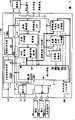
图1是表示车辆用图像摄影装置的一个实施例的电路图。FIG. 1 is a circuit diagram showing an example of a vehicle imaging device.
图2是用来说明图像系统电源的控制处理的时间分配图。FIG. 2 is a timing chart for explaining the control processing of the video system power supply.
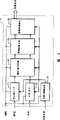
图3是总线缓冲器及其周边的电路图。Fig. 3 is a circuit diagram of a bus buffer and its surroundings.
图4是用来说明用总线缓冲器的图像系统电源的控制处理的时间分配图。Fig. 4 is a timing diagram for explaining the control processing of the video system power supply using the bus buffer.
图5是表示第1实施例的变形例的流程图。Fig. 5 is a flowchart showing a modified example of the first embodiment.
图6是表示视频解码器的电路图。Fig. 6 is a circuit diagram showing a video decoder.
具体实施方式Detailed ways
如图1中所示图像摄影装置100包含主控制系统电源1,图像系统电源2,通信I/F(接口)3,微计算机4,总线缓冲器5,字段存储器6,视频解码器7,输入I/F 8,存储器控制部9,图像数据工作存储器10,图像数据不易失保存存储器11而构成。As shown in Fig. 1, the
通信I/F 3,微计算机4,总线缓冲器5,存储器控制部9,图像数据工作存储器10,图像数据不易失保存存储器11包含于主控制部,字段存储器6,视频解码器7包含于图像处理部。Communication I/
此外,在图像摄影装置100中,备有包括进行图像数据的发送的与外部机器的通信的通信模块端子Tx、Rx,传感器信号端子A、B,被盗检测信号输入端子C,将电源供给到摄像机101和辅助光源的摄像机电源端子,输入来自摄像机101的影像信号的NTSC端子。In addition, in the
主控制系统电源1将来自未画出的电池的电压(+B)变换成规定的电压(VDD1),供给到通信I/F 3、微计算机4、总线缓冲器5、输入I/F 8、存储器控制部9、图像数据工作存储器10、图像数据不易失保存存储器11。此外,主控制系统电源1还进行微计算机4的工作的监视。也就是说,微计算机4从WD端子输出规定周期的脉冲信号,主控制系统电源1由CK端子接收该脉冲信号。The main control system power supply 1 converts the voltage (+B) from a battery (not shown) into a predetermined voltage (VDD1), and supplies it to the communication I/
主控制系统电源1一检测到该脉冲信号的前沿或后沿就将计时器清零。计时器的值超过规定的值(在规定的时间内未收到该脉冲信号)时,判定成微计算机4的工作异常,从RESET端子向微计算机4的RESET端子送出复位信号,使微计算机4复位。Once the main control system power supply 1 detects the leading or trailing edge of the pulse signal, the timer will be cleared. When the value of the timer exceeds the prescribed value (do not receive this pulse signal in the prescribed time), it is determined that the operation of the microcomputer 4 is abnormal, and a reset signal is sent from the RESET terminal to the RESET terminal of the microcomputer 4, so that the microcomputer 4 reset.
再者,虽然在图1中,在端子名之上带有上划线符号者是按负逻辑(低电平有效)工作的,但是在本实施例的文中不附加上划线符号地描述。In addition, in FIG. 1, those with an overlined symbol above the terminal name operate in negative logic (active low), but this embodiment is described without an underlined symbol.
图像系统电源2将来自来画出的电池的电压(+B)变换成规定的电压(WDD2),供给到字段存储器6、视频解码器7、摄像机101、摄像机用辅助光源(经由摄像机电源端子)。图像系统电源2从EN端子取入从微计算机4的DC_EN端子所输出的控制信号,基于该控制信号的内容进行电压的供给/停止。The image
通信I/F 3是进行微计算机4与外部机器的通信的电路,成为对应于所连接的外部机器的通信标准的电路构成。作为外部机器有连接于车内LAN(局域网)的车载机器、进行与车外的通信的通信机器。The communication I/
微计算机4进行主控制、条件判定、图像处理结束检测,包含未画出的公知的CPU、ROM、RAM等而构成。微计算机4由储存于ROM或RAM的控制程序和数据进行控制。The microcomputer 4 performs main control, condition judgment, and image processing end detection, and is configured including a known CPU, ROM, RAM, etc. not shown. The microcomputer 4 is controlled by control programs and data stored in ROM or RAM.
总线缓冲器5进行字段存储器6与微计算机4之间的数据传送路(数据总线)的连接(ON)/阻断(OFF),靠微计算机4的指令(来自CS1的控制信号)工作。The
视频解码器7将从摄像机101所进来的影像信号(NTSC信号:模拟信号)变换成图像数据。视频解码器7用例如冲电气工业的MSM7664TB之类公知的解码器LSI。这种视频解码器7将所输入的NTSC信号中所含有的复合信号(组合了影像信号、彩色同步信号、复合同步信号的复合影像信号)进行AD变换而得到由RGB(红绿蓝)信号组成的数字图像数据。在本构成中,生成每秒60帧的数字图像数据。The video decoder 7 converts the video signal (NTSC signal: analog signal) received from the
视频解码器7如图6中所示,备有NTCS输入I/F电路71,时钟/同步信号电路72,休眠/唤醒控制电路73,模拟/数字变换电路74,数字图像数据生成电路75和数字图像数据输出电路76。微计算机4一使DC_EN端子接通,电压VDD2就从图像系统电源2供给到各个电路71至76。休眠控制信号从微计算机4输入到体眠/唤醒控制电路73。As shown in Figure 6, video decoder 7 is provided with NTCS input I/
如果微计算机4将体眠控制信号设定成Hi电平,则休眠/唤醒控制电路73检测到它而输出控制信号并将电路71、72、74、75和76设定成作为低消耗电力的体眠状态。另一方面,如果微计算机4将休眠控制信号设定成Lo电平,则休眠/唤醒控制电路73将电路71、72、74、75和76设定成唤醒状态。在唤醒状态下,电路74至76同步于时钟/同步信号电路72所输出的时钟信号而工作。在休眠状态下,即使供给电压VDD2实际的工作也停止。视频解码器7的消耗电流在休眠状态下为10mA,在唤醒状态下为150mA。If the microcomputer 4 sets the body sleep control signal to Hi level, the sleep/
字段存储器6是FIFO(先入/先出)存储器,将在视频解码器7中所生成的数字图像数据逐帧储存到由微计算机4读出。The
输入I/F 8取入来自传感器信号端子A、B,被盗检测信号输入端子C的信号,调整电压平等以便在微计算机4中能够处理。The input I/F 8 takes in signals from the sensor signal terminals A and B, and the theft detection signal input terminal C, and adjusts the voltage equalization so that it can be processed in the microcomputer 4.
存储器控制部9按微计算机4的指令(来自RD、WRO、WR1、CS3、CS2的控制信号)对图像数据工作存储器10、图像数据不易失保存存储器11的某个进行图像数据的读写。The memory control unit 9 reads and writes image data to any one of the image data working memory 10 and the image data
图像数据工作存储器10是暂时保持微计算机4从字段存储器6所取入的数字图像数据用的工作区。为了降低微计算机4的负载,来自微计算机4的数字图像数据的传送采用DMA(直接存储器访问)方式来进行。The image data work memory 10 is a work area for temporarily storing the digital image data that the microcomputer 4 fetches from the
图像数据不易失保存存储器11由即使闪存存储器等车辆用图像摄影装置100的电源成为切断状态,数据内容的储存保持也是可能的存储器来构成,将从图像数据工作存储器10所取入的数字图像数据变换成由JPEG(联合图像专家组)等规定的图像格式组成的图像数据储存保持。The image data
传感器信号A端子取入来自检测对车辆的接近的接近传感器102的信号。作为接近传感器102,有采用超声波检测对车辆的接近者,采用电波检测对车辆的接近者等。The sensor signal A terminal takes in a signal from the
传感器信号B端子取入来自检测对相对于车辆的侵入的侵入传感器103的信号。作为侵入传感器103,有检测车辆的倾斜者(可以检测用抢险车的牵引的被盗或搭载在其他车辆上的被盗),检测玻璃被割者等。The sensor signal B terminal takes in a signal from the intrusion sensor 103 that detects intrusion into the vehicle. The intrusion sensor 103 detects a person who is leaning on the vehicle (can detect a person who is towed by an emergency vehicle or a person who is mounted on another vehicle), detects a person whose glass has been cut, and the like.
就传感器信号端子的数目和传感器的功能而言,只要能够检测相对于车辆的接近和侵入即可,不特别设置制约。In terms of the number of sensor signal terminals and the functions of the sensors, no restrictions are particularly set as long as approach and intrusion with respect to the vehicle can be detected.
被盗检测信号端子C取入从安全性ECU 104送出的被盗检测信号。安全性BCU 104如果检测到车门或行李箱被打开就发出警报。作为警报,有使车辆的电话呼叫,点亮紧急警告灯等动作。在本实施例中,作为被盗检测信号取入安全性ECU 104输出的喇叭鸣响指令信号。The theft detection signal terminal C takes in the theft detection signal sent from the
本车辆用图像摄影装置100的基本的功能,在检测到被盗检测信号时在视频解码器7中变换来自摄像机101的模拟影像信号而取得图像数据并储存于图像数据不易失保存存储器11。然后,经由通信I/F3、通信模块端子Tx、Rx向车外的管理中心、车辆的所有者等发送,作为被盗事件的证据,促进检举犯人,或者通过用摄像机101监视车辆而防止车辆的被盗。再者,发送已结束的图像数据依次消去。The basic function of the
接下来,就微计算机4进行的图像系统电源2的控制处理用图2的时间分配图和图5的流程图进行说明。再者,本处理包含于储存于微计算机4的ROM或RAM的控制程序,与其他处理一起重复进行。Next, the control process of the image
首先,来自未画出的电池的电源一供给,主控制系统电源1就成为接通状态,电压VDD1供给到通信I/F(接口)3、微计算机4、总线缓冲器5、输入I/F 8、存储器控制部9、图像数据工作存储器10、图像数据不易失保存存储器11(步骤S11)。First, when power from a battery (not shown) is supplied, the main control system power supply 1 is turned on, and the voltage VDD1 is supplied to the communication I/F (interface) 3, microcomputer 4,
经由被盗检测信号端子C检测到来自安全性ECU 104的被盗检测信号时或者传感器102检测到可疑者的人体的接近(断→通状态)(S12:是),微计算机4为了使图像系统电源2成为接通状态,使DC_EN端子成为接通状态。借此,电压VDD2从图像系统电源2供给到字段存储器6、视频解码器7、摄像机101、摄像机101用辅助光源(S13)。然后,微计算机4对视频解码器7送出开始编码处理的指令(图像摄影触发信号),视频解码器7成为规定时间唤醒状态而开始解码处理(图2的时刻Ta,图5的S14)。When the theft detection signal from the
规定的时间(也就是规定的图像张数)把来自摄像机101的影像信号变换成数字图像数据而结束解码处理(S15:是)时,视频解码器7就向微计算机4送出解码处理结束通知。微计算机4一收到解码处理结束通知就向视频解码器7送出指令,使视频解码器7成为休眠状态(图2的时刻Tb,图5的S16)。When the video signal from the
然后,侵入传感器103检测到人体的侵入时(断→通状态)(S17:是),微计算机4对视频解码器7送出开始解码处理的指令(图像摄影触发信号),视频解码器7成为规定时间唤醒状态(图2的时刻Tc,图5的S18)。此时的成为唤醒状态的时间比S14中成为唤醒状态的时间要短。也就是说,在S14里,由于图像系统电源2成为接通状态后立即唤醒,所以估计摄像机101或视频解码器7的电源投入后直到工作稳定的迟延时间而设定成为唤醒状态的时间。与此相对,在S18中,由于图像系统电源2成为接通状态经过足够的时间,摄像机101或视频解码器7的工作已经稳定,所以成为唤醒状态的时间可以缩短。Then, when the intrusion sensor 103 detects the intrusion of the human body (off→on state) (S17: Yes), the microcomputer 4 sends an instruction (image shooting trigger signal) to the video decoder 7 to start the decoding process, and the video decoder 7 becomes a predetermined Time wake-up state (time Tc in FIG. 2 , S18 in FIG. 5 ). The time to be in the awake state at this time is shorter than the time to be in the awake state in S14. That is, in S14, since the video
规定的时间(也就是规定的图像张数)把来自摄像机101的影像信号变换成数字图像数据而结束解码处理(S19:是)时,视频解码器7就向微计算机4送出解码处理结束通知。微计算机4一收到解码处理结束通知就向视频解码器7送出指令,使视频解码器7成为休眠状态(图2的时刻Td,图5的S20)。When the video signal from the
再者,在从S13至S20的处理之间,未检测到来自安全性ECU104的被盗检测信号时(通→断状态),微计算机4使DC_EN端子成为切断状态。借此,电压VDD2从图像系统电源2向字段存储器6、视频解码器7、摄像机101、摄像机101用辅助光源的供给停止。此外,本控制处理结束。此外,也可以在S16中使视频解码器7成为休眠状态之际使图像系统电源2成为切断状态,在S17中检测到侵入之际使图像系统电源2成为接通状态。In addition, when the theft detection signal from the security ECU104 is not detected (on→off state) between processes from S13 to S20, the microcomputer 4 makes DC_EN terminal into an off state. Accordingly, the supply of the voltage VDD2 from the video
接下来,就总线缓冲器5的动作用图3和图4进行说明。总线缓冲器5在数据总线端子(DB0~DB15)与字段存储器6之间的数据总线端子(DO0~DO15)之间(数据总线)上夹插缓冲器电路5b(例如16个),由共同的门控制电路5a进行数据总线的连接/阻断的动作。Next, the operation of the
在图4中,经由被盗检测信号端子C来自安全性ECU 104的被盗检测信号检测到时或接近传感器102检测到人体的接近时(断→通状态),微计算机4为了使图像系统电源2成为接通状态,使DC_EN端子成为接通状态。借此,从图像系统电源2把电压VDD2供给到字段存储器6、视频解码器7、摄像机101、摄像机101用辅助光源。然后,微计算机4对视频解码器7送出开始解码处理的指令,视频解码器7成为唤醒状态而开始解码处理。In FIG. 4, when the theft detection signal from the
然后,微计算机4调查字段存储器6中有没有数字图像数据,在有数字图像数据时读入该数字图像数据并写入图像数据工作存储器10。Then, the microcomputer 4 checks whether there is digital image data in the
此时,如果从微计算机4的CS(芯片选择)1端子输出L电平信号(0V),则总线缓冲器5的门控制电路5a成为接通状态,各数据总线上的总线缓冲器电路5b成为接通状态,微计算机4与字段存储器6之间的数据总线成为连接状态。然后,H电平输入到字段存储器6的CE(Chip_Enable)端子,可从字段存储器6读入数字图像数据(图4的有效的期间)。然后,一结束数字图像数据的读入,就从微计算机4的CS1端子输出H电平信号(5V),而总线缓冲器5的门控制电路5a成为切断状态,各数据总线上的总线缓冲器电路5b成为切断状态,微计算机4与字段存储器6之间的数据总线成为阻断状态。At this time, if an L level signal (0V) is output from the CS (chip select) 1 terminal of the microcomputer 4, the
在未夹插总线缓冲器5的状态下主控制系统电源1为接通状态而图像系统电源2为切断状态时,电流以VDD1~数据总线~字段存储器6的路径流动,存在着破坏字段存储器6内部的元件的可能性。但是,在夹插总线缓冲器5的状态下主控制系统电源1为接通状态而图像系统电源2为切断状态时,从微计算机4的CS1端子输出H电平信号而使总线缓冲器5的门成为切断状态,如果使微计算机4与字段存储器6之间的数据总线成为电气上阻断状态则数据总线成为高阻抗状态。因而,VDD1~数据总线~字段存储器6的路径不能形成,就不会破坏字段存储器6内部的元件。In the state where the
在本构成中,也可以把本来为了读出字段存储器6的数据而采用的CS1信号用于总线缓冲器5的门电路5a的控制。借此,在读出字段存储器6的数据时以,外数据总线成为阻断状态也就是高阻抗状态。由此,不用设置专用电路而可以使数据总线成为高阻抗状态。In this configuration, the CS1 signal originally used for reading data from the
此外,侵入传感器103在检测到可疑者等人体的侵入时也是同样的。The same applies when the intrusion sensor 103 detects the intrusion of a human body such as a suspicious person.
这样一来,在本实施例中,由于视频解码器7仅在摄像机101的摄影定时时成为唤醒状态,一把图像数据传送到字段存储器6就成为休眠状态,所以成为唤醒状态而工作的期间很短。由此,可以降低消耗电力。此外,传送到字段存储器6的图像数据从字段存储器6传送到图像数据工作存储器10,由图像数据工作存储器10进行图像大小的调整或图像数据的压缩。由于电力从与把电力供给到视频解码器7或字段存储器6的图像系统电源2不同的主控制系统电源1供给到图像数据工作存储器10,所以即使视频解码器7或字段存储器6成为休眠状态也可以工作。In this way, in this embodiment, since the video decoder 7 is in the wake-up state only at the shooting timing of the
此外,在本实施例中,由于在被盗检测信号接通状态期间使图像系统电源2成为接通状态,所以在人体相对于车辆的侵入时电压预先供给到摄像机101,因此摄像机101可以没有迟延地摄影。In addition, in this embodiment, since the image
以上,虽然说明了车辆用图像摄影装置的实施例,但是这些毕竟只不过是举例表示,本装置不限定于这些,可进行种种的变更。As mentioned above, although the embodiment of the imaging apparatus for vehicles was demonstrated, these are merely examples after all, and this apparatus is not limited to these, Various changes are possible.
Claims (6)
Translated fromChineseApplications Claiming Priority (2)
| Application Number | Priority Date | Filing Date | Title |
|---|---|---|---|
| JP2004319741 | 2004-11-02 | ||
| JP2004319741AJP4844795B2 (en) | 2004-11-02 | 2004-11-02 | Vehicle image capturing device |
Publications (2)
| Publication Number | Publication Date |
|---|---|
| CN1770824A CN1770824A (en) | 2006-05-10 |
| CN100399802Ctrue CN100399802C (en) | 2008-07-02 |
Family
ID=36261318
Family Applications (1)
| Application Number | Title | Priority Date | Filing Date |
|---|---|---|---|
| CNB200510120109XAExpired - Fee RelatedCN100399802C (en) | 2004-11-02 | 2005-11-02 | Vehicle imaging device and method |
Country Status (5)
| Country | Link |
|---|---|
| US (1) | US20060092278A1 (en) |
| JP (1) | JP4844795B2 (en) |
| KR (1) | KR100665145B1 (en) |
| CN (1) | CN100399802C (en) |
| DE (1) | DE102005051624A1 (en) |
Cited By (1)
| Publication number | Priority date | Publication date | Assignee | Title |
|---|---|---|---|---|
| CN105818751A (en)* | 2015-01-07 | 2016-08-03 | 鸿富锦精密工业(深圳)有限公司 | Vehicle, automatic adjusting system applied to same and automatic adjusting method |
Families Citing this family (25)
| Publication number | Priority date | Publication date | Assignee | Title |
|---|---|---|---|---|
| JP2008054085A (en)* | 2006-08-25 | 2008-03-06 | Hitachi Ltd | Broadcast receiving apparatus and activation method thereof |
| EP1921867B1 (en)* | 2006-10-17 | 2016-05-25 | Harman Becker Automotive Systems GmbH | Sensor assisted video compression |
| JP2009248711A (en)* | 2008-04-04 | 2009-10-29 | Denso Corp | On-vehicle communication system |
| US9141863B2 (en)* | 2008-07-21 | 2015-09-22 | Facefirst, Llc | Managed biometric-based notification system and method |
| DE202009018205U1 (en) | 2009-06-02 | 2011-05-05 | Volkswagen Ag | Device for actuating a closing element of a vehicle |
| JP5316995B2 (en)* | 2009-10-26 | 2013-10-16 | 株式会社ユピテル | Vehicle recording device |
| DE102010011767A1 (en)* | 2010-03-17 | 2011-09-22 | Brose Fahrzeugteile Gmbh & Co. Kg, Hallstadt | Method for sensory detection of an operator event |
| US8607084B2 (en)* | 2010-06-11 | 2013-12-10 | Via Technologies, Inc. | Computer system and method for saving power consumption by placing a second computer portion into a sleep mode after completed transfering image data to a first computer portion |
| KR101241803B1 (en) | 2010-06-25 | 2013-03-14 | 엠텍비젼 주식회사 | Multi-camera video recording device and method for vehicle using multi-camera system |
| US9842261B2 (en)* | 2011-05-24 | 2017-12-12 | Nissan Motor Co., Ltd. | Vehicle monitoring device and method of monitoring vehicle |
| DE112011105828B4 (en)* | 2011-11-09 | 2016-01-14 | Toyota Jidosha Kabushiki Kaisha | Electronic control devices and microcomputer control methods with idle mode |
| TW201348036A (en)* | 2012-05-31 | 2013-12-01 | Yottastor Information Technology Inc | Vehicle monitoring system |
| DE102013102951A1 (en)* | 2013-03-22 | 2014-09-25 | Conti Temic Microelectronic Gmbh | Method for monitoring a vehicle |
| US9390567B2 (en)* | 2014-02-05 | 2016-07-12 | Harman International Industries, Incorporated | Self-monitoring and alert system for intelligent vehicle |
| KR101533814B1 (en)* | 2014-03-13 | 2015-07-03 | 주식회사 유라코퍼레이션 | Apparatus and Method of recording event based image data |
| CN104627126B (en)* | 2015-01-30 | 2017-01-18 | 中国矿业大学 | Vehicle anti-theft system and method based on heterogeneous network |
| KR101600287B1 (en)* | 2015-03-12 | 2016-03-08 | 한국항공대학교산학협력단 | Low power smart video device and control method for varying the operation mode according to the energy level of the battery |
| CN106982354B (en)* | 2017-04-02 | 2019-12-20 | 杭州如道科技有限公司 | Split type high definition network camera |
| US11279321B2 (en)* | 2017-06-27 | 2022-03-22 | Sony Semiconductor Solutions Corporation | Imaging apparatus having a reduced power consumption mode and mode that generates a captured image |
| FR3078224B1 (en)* | 2018-02-16 | 2020-02-07 | Renault S.A.S | METHOD FOR MONITORING A PARKING MOTOR VEHICLE ENVIRONMENT INCLUDING AN ASYNCHRONOUS CAMERA |
| JP7215231B2 (en)* | 2019-03-04 | 2023-01-31 | トヨタ自動車株式会社 | Information processing device, detection method and program |
| DE102019203834B4 (en)* | 2019-03-18 | 2024-05-08 | Continental Automotive Technologies GmbH | Vehicle and method for monitoring a vehicle in a parked state |
| JP7143797B2 (en)* | 2019-03-20 | 2022-09-29 | 株式会社デンソー | Power control device for in-vehicle camera module |
| US11616932B1 (en)* | 2020-12-15 | 2023-03-28 | Ambarella International Lp | Car security camera triggering mechanism |
| CN115476817A (en)* | 2021-06-15 | 2022-12-16 | 北京汽车股份有限公司 | Vehicle control method, controller and vehicle |
Citations (8)
| Publication number | Priority date | Publication date | Assignee | Title |
|---|---|---|---|---|
| US5939975A (en)* | 1996-09-19 | 1999-08-17 | Nds Ltd. | Theft prevention system and method |
| CN2435294Y (en)* | 2000-04-26 | 2001-06-20 | 罗伟 | Wireless image anti-theft means for vehicle |
| JP2001338378A (en)* | 2000-05-30 | 2001-12-07 | Sanyo Electric Service Co Ltd | Device for reporting abnormality in vehicle and, device for reporting, photographing and recording intrusion into vehicle |
| JP2002187503A (en)* | 2000-12-22 | 2002-07-02 | Denso Corp | Control system of on-vehicle device, on-vehicle device and receiver for keyless entry system |
| JP2002308054A (en)* | 2001-04-09 | 2002-10-23 | Denso Corp | Gateway device |
| JP2003032668A (en)* | 2001-07-19 | 2003-01-31 | Seiwa Electric Mfg Co Ltd | Digital camera for monitoring |
| CN1451571A (en)* | 2002-04-12 | 2003-10-29 | 旭丽股份有限公司 | Automobile Anti-theft Surveillance Secret Recording System |
| US20040140885A1 (en)* | 2003-01-17 | 2004-07-22 | Slicker James M. | Vehicle security system |
Family Cites Families (25)
| Publication number | Priority date | Publication date | Assignee | Title |
|---|---|---|---|---|
| JPH03100700U (en)* | 1990-01-31 | 1991-10-21 | ||
| US6002326A (en)* | 1994-09-19 | 1999-12-14 | Valerie Turner | Automotive vehicle anti-theft and anti-vandalism and anti-carjacking system |
| KR0184984B1 (en)* | 1995-06-09 | 1999-05-01 | 김광호 | Crime prevention camcoder using human body perception sensor & control method |
| US6002436A (en)* | 1997-08-28 | 1999-12-14 | Flashpoint Technology, Inc. | Method and system for auto wake-up for time lapse image capture in an image capture unit |
| KR19990051660A (en)* | 1997-12-19 | 1999-07-05 | 정몽규 | Shooting device and the method when the vehicle is stolen |
| US6131167A (en)* | 1997-12-31 | 2000-10-10 | Intel Corporation | Method and apparatus to reduce power consumption on a bus |
| US6943834B1 (en)* | 1998-02-06 | 2005-09-13 | Canon Kabushiki Kaisha | Apparatus and method of converting image data to video signals |
| JPH11225306A (en)* | 1998-02-06 | 1999-08-17 | Canon Inc | Image processing apparatus and computer-readable storage medium |
| US6741165B1 (en)* | 1999-06-04 | 2004-05-25 | Intel Corporation | Using an imaging device for security/emergency applications |
| JP2001298729A (en)* | 2000-04-12 | 2001-10-26 | Toshiba Corp | Monitoring system |
| KR200222732Y1 (en) | 2000-09-25 | 2001-05-15 | 라영준 | A wide inspect system for car |
| JP2002125301A (en)* | 2000-10-13 | 2002-04-26 | Suzuki Motor Corp | Power-saving device for on-vehicle equipment, power- saving control device for the on-vehicle equipment, power-saving system for the on-vehicle equipment and storage medium |
| JP2002156676A (en)* | 2000-11-20 | 2002-05-31 | Olympus Optical Co Ltd | Photographing device with shake detecting function |
| US7058458B2 (en)* | 2001-03-26 | 2006-06-06 | Matsushita Electric Industrial Co., Ltd. | Power controller |
| US6525653B1 (en)* | 2001-08-10 | 2003-02-25 | Annie Rigmaiden | Vehicle security and monitoring system |
| KR200255524Y1 (en) | 2001-08-18 | 2001-12-13 | 이성용 | Monitoring apparatus for antithief and photographing of accident |
| JP3541837B2 (en)* | 2002-01-30 | 2004-07-14 | ミノルタ株式会社 | Digital camera |
| JP2003284046A (en)* | 2002-03-25 | 2003-10-03 | Canon Electronics Inc | Monitoring camera unit |
| CA2478872C (en)* | 2002-03-29 | 2009-09-08 | Nagoya Toyopet Co., Ltd. | Image processing system for identifying car stealer |
| JP2004030480A (en)* | 2002-06-28 | 2004-01-29 | Fujitsu Ten Ltd | Theft preventing system, theft prevention device, theft prevention cooperating device, and multimedia device |
| JP3972891B2 (en)* | 2003-11-06 | 2007-09-05 | 株式会社デンソー | Vehicle monitoring system |
| US7342611B2 (en)* | 2003-12-10 | 2008-03-11 | Hewlett-Packard Development Company, L.P. | Method for rapid power-on to first picture in a digital camera |
| US7064657B2 (en)* | 2004-01-08 | 2006-06-20 | International Business Machines Corporation | Method and system for accessing and viewing images of a vehicle interior |
| US20060209190A1 (en)* | 2005-03-04 | 2006-09-21 | Walters Kenneth S | Vehicle directional monitoring system |
| US20060250501A1 (en)* | 2005-05-06 | 2006-11-09 | Widmann Glenn R | Vehicle security monitor system and method |
- 2004
- 2004-11-02JPJP2004319741Apatent/JP4844795B2/ennot_activeExpired - Fee Related
- 2005
- 2005-10-27DEDE200510051624patent/DE102005051624A1/ennot_activeWithdrawn
- 2005-11-01KRKR20050103644Apatent/KR100665145B1/ennot_activeExpired - Fee Related
- 2005-11-02USUS11/264,388patent/US20060092278A1/ennot_activeAbandoned
- 2005-11-02CNCNB200510120109XApatent/CN100399802C/ennot_activeExpired - Fee Related
Patent Citations (8)
| Publication number | Priority date | Publication date | Assignee | Title |
|---|---|---|---|---|
| US5939975A (en)* | 1996-09-19 | 1999-08-17 | Nds Ltd. | Theft prevention system and method |
| CN2435294Y (en)* | 2000-04-26 | 2001-06-20 | 罗伟 | Wireless image anti-theft means for vehicle |
| JP2001338378A (en)* | 2000-05-30 | 2001-12-07 | Sanyo Electric Service Co Ltd | Device for reporting abnormality in vehicle and, device for reporting, photographing and recording intrusion into vehicle |
| JP2002187503A (en)* | 2000-12-22 | 2002-07-02 | Denso Corp | Control system of on-vehicle device, on-vehicle device and receiver for keyless entry system |
| JP2002308054A (en)* | 2001-04-09 | 2002-10-23 | Denso Corp | Gateway device |
| JP2003032668A (en)* | 2001-07-19 | 2003-01-31 | Seiwa Electric Mfg Co Ltd | Digital camera for monitoring |
| CN1451571A (en)* | 2002-04-12 | 2003-10-29 | 旭丽股份有限公司 | Automobile Anti-theft Surveillance Secret Recording System |
| US20040140885A1 (en)* | 2003-01-17 | 2004-07-22 | Slicker James M. | Vehicle security system |
Cited By (2)
| Publication number | Priority date | Publication date | Assignee | Title |
|---|---|---|---|---|
| CN105818751A (en)* | 2015-01-07 | 2016-08-03 | 鸿富锦精密工业(深圳)有限公司 | Vehicle, automatic adjusting system applied to same and automatic adjusting method |
| CN105818751B (en)* | 2015-01-07 | 2018-06-26 | 中山市云创知识产权服务有限公司 | Vehicle and automatic regulating system and Automatic adjustment method applied to the vehicle |
Also Published As
| Publication number | Publication date |
|---|---|
| KR100665145B1 (en) | 2007-01-09 |
| DE102005051624A1 (en) | 2006-07-06 |
| JP4844795B2 (en) | 2011-12-28 |
| JP2006135435A (en) | 2006-05-25 |
| CN1770824A (en) | 2006-05-10 |
| KR20060052369A (en) | 2006-05-19 |
| US20060092278A1 (en) | 2006-05-04 |
Similar Documents
| Publication | Publication Date | Title |
|---|---|---|
| CN100399802C (en) | Vehicle imaging device and method | |
| KR101569520B1 (en) | Method for Saving of Moving Picture in Car Blackbox | |
| JP6669240B1 (en) | Recording control device, recording control system, recording control method, and recording control program | |
| JP2005141451A (en) | Vehicle monitoring system | |
| CN108639008A (en) | A kind of intelligence Security for fuel tank alarm system and method | |
| JPH11242733A (en) | Power saving controller | |
| US10524295B2 (en) | Environmental surveillance system and method of driving portable information capture device | |
| CN114640830B (en) | Monitoring device and method and automobile data recorder | |
| TWM331716U (en) | Multi-functional vehicle anti-theft and anti-robbery monitoring device | |
| CN108615272B (en) | Driving recorder | |
| CN108639013A (en) | New-energy automobile burglary-resisting system | |
| JP3894122B2 (en) | Object detection apparatus and method | |
| KR101418892B1 (en) | Front-end event detector and low-power camera system using thereof | |
| CN115278013A (en) | Camera and method for controlling camera | |
| CN222291684U (en) | Abnormal wake-up system and vehicle navigation equipment | |
| CN201951410U (en) | Automobile anti-theft automatic snapshot system | |
| CN117302109A (en) | Vibration monitoring method and device and vehicle | |
| CN108063893A (en) | A kind of monitor camera energy saver | |
| CN1445730A (en) | Image storage alarming method and system | |
| KR100827630B1 (en) | Car Multimedia System | |
| JP2008078809A (en) | Image processor for vehicle | |
| JP7649233B2 (en) | Recording control device and recording control method | |
| JP2004128899A (en) | Monitor camera system | |
| CN118784776A (en) | A motion detection energy-saving method based on image comparison algorithm | |
| JP2002334386A (en) | Object detection system and image processing method |
Legal Events
| Date | Code | Title | Description |
|---|---|---|---|
| C06 | Publication | ||
| PB01 | Publication | ||
| C10 | Entry into substantive examination | ||
| SE01 | Entry into force of request for substantive examination | ||
| C14 | Grant of patent or utility model | ||
| GR01 | Patent grant | ||
| CF01 | Termination of patent right due to non-payment of annual fee | ||
| CF01 | Termination of patent right due to non-payment of annual fee | Granted publication date:20080702 Termination date:20171102 |