CN100399790C - Watermark Information Detection Method - Google Patents
Watermark Information Detection MethodDownload PDFInfo
- Publication number
- CN100399790C CN100399790CCNB2004800075750ACN200480007575ACN100399790CCN 100399790 CCN100399790 CCN 100399790CCN B2004800075750 ACNB2004800075750 ACN B2004800075750ACN 200480007575 ACN200480007575 ACN 200480007575ACN 100399790 CCN100399790 CCN 100399790C
- Authority
- CN
- China
- Prior art keywords
- signal
- unit
- image
- dot pattern
- embedded
- Prior art date
- Legal status (The legal status is an assumption and is not a legal conclusion. Google has not performed a legal analysis and makes no representation as to the accuracy of the status listed.)
- Expired - Fee Related
Links
Images


Classifications
- H—ELECTRICITY
- H04—ELECTRIC COMMUNICATION TECHNIQUE
- H04N—PICTORIAL COMMUNICATION, e.g. TELEVISION
- H04N1/00—Scanning, transmission or reproduction of documents or the like, e.g. facsimile transmission; Details thereof
- H04N1/387—Composing, repositioning or otherwise geometrically modifying originals
- H—ELECTRICITY
- H04—ELECTRIC COMMUNICATION TECHNIQUE
- H04N—PICTORIAL COMMUNICATION, e.g. TELEVISION
- H04N1/00—Scanning, transmission or reproduction of documents or the like, e.g. facsimile transmission; Details thereof
- H04N1/32—Circuits or arrangements for control or supervision between transmitter and receiver or between image input and image output device, e.g. between a still-image camera and its memory or between a still-image camera and a printer device
- H04N1/32101—Display, printing, storage or transmission of additional information, e.g. ID code, date and time or title
- H04N1/32144—Display, printing, storage or transmission of additional information, e.g. ID code, date and time or title embedded in the image data, i.e. enclosed or integrated in the image, e.g. watermark, super-imposed logo or stamp
- H04N1/32149—Methods relating to embedding, encoding, decoding, detection or retrieval operations
- H04N1/32203—Spatial or amplitude domain methods
- G—PHYSICS
- G06—COMPUTING OR CALCULATING; COUNTING
- G06V—IMAGE OR VIDEO RECOGNITION OR UNDERSTANDING
- G06V30/00—Character recognition; Recognising digital ink; Document-oriented image-based pattern recognition
- G06V30/40—Document-oriented image-based pattern recognition
- H—ELECTRICITY
- H04—ELECTRIC COMMUNICATION TECHNIQUE
- H04N—PICTORIAL COMMUNICATION, e.g. TELEVISION
- H04N1/00—Scanning, transmission or reproduction of documents or the like, e.g. facsimile transmission; Details thereof
- H04N1/32—Circuits or arrangements for control or supervision between transmitter and receiver or between image input and image output device, e.g. between a still-image camera and its memory or between a still-image camera and a printer device
- H04N1/32101—Display, printing, storage or transmission of additional information, e.g. ID code, date and time or title
- H04N1/32144—Display, printing, storage or transmission of additional information, e.g. ID code, date and time or title embedded in the image data, i.e. enclosed or integrated in the image, e.g. watermark, super-imposed logo or stamp
- H04N1/32149—Methods relating to embedding, encoding, decoding, detection or retrieval operations
- H04N1/32203—Spatial or amplitude domain methods
- H04N1/32224—Replacing pixels of an image with other pixels from the same image, e.g. texture block coding
- H—ELECTRICITY
- H04—ELECTRIC COMMUNICATION TECHNIQUE
- H04N—PICTORIAL COMMUNICATION, e.g. TELEVISION
- H04N1/00—Scanning, transmission or reproduction of documents or the like, e.g. facsimile transmission; Details thereof
- H04N1/32—Circuits or arrangements for control or supervision between transmitter and receiver or between image input and image output device, e.g. between a still-image camera and its memory or between a still-image camera and a printer device
- H04N1/32101—Display, printing, storage or transmission of additional information, e.g. ID code, date and time or title
- H04N1/32144—Display, printing, storage or transmission of additional information, e.g. ID code, date and time or title embedded in the image data, i.e. enclosed or integrated in the image, e.g. watermark, super-imposed logo or stamp
- H04N1/32149—Methods relating to embedding, encoding, decoding, detection or retrieval operations
- H04N1/32203—Spatial or amplitude domain methods
- H04N1/32261—Spatial or amplitude domain methods in binary data
- H—ELECTRICITY
- H04—ELECTRIC COMMUNICATION TECHNIQUE
- H04N—PICTORIAL COMMUNICATION, e.g. TELEVISION
- H04N1/00—Scanning, transmission or reproduction of documents or the like, e.g. facsimile transmission; Details thereof
- H04N1/32—Circuits or arrangements for control or supervision between transmitter and receiver or between image input and image output device, e.g. between a still-image camera and its memory or between a still-image camera and a printer device
- H04N1/32101—Display, printing, storage or transmission of additional information, e.g. ID code, date and time or title
- H04N1/32144—Display, printing, storage or transmission of additional information, e.g. ID code, date and time or title embedded in the image data, i.e. enclosed or integrated in the image, e.g. watermark, super-imposed logo or stamp
- H04N1/32149—Methods relating to embedding, encoding, decoding, detection or retrieval operations
- H04N1/32288—Multiple embedding, e.g. cocktail embedding, or redundant embedding, e.g. repeating the additional information at a plurality of locations in the image
- H04N1/32293—Repeating the additional information in a regular pattern
- H—ELECTRICITY
- H04—ELECTRIC COMMUNICATION TECHNIQUE
- H04N—PICTORIAL COMMUNICATION, e.g. TELEVISION
- H04N1/00—Scanning, transmission or reproduction of documents or the like, e.g. facsimile transmission; Details thereof
- H04N1/32—Circuits or arrangements for control or supervision between transmitter and receiver or between image input and image output device, e.g. between a still-image camera and its memory or between a still-image camera and a printer device
- H04N1/32101—Display, printing, storage or transmission of additional information, e.g. ID code, date and time or title
- H04N1/32144—Display, printing, storage or transmission of additional information, e.g. ID code, date and time or title embedded in the image data, i.e. enclosed or integrated in the image, e.g. watermark, super-imposed logo or stamp
- H04N1/32352—Controlling detectability or arrangements to facilitate detection or retrieval of the embedded information, e.g. using markers
- H—ELECTRICITY
- H04—ELECTRIC COMMUNICATION TECHNIQUE
- H04N—PICTORIAL COMMUNICATION, e.g. TELEVISION
- H04N5/00—Details of television systems
- H04N5/76—Television signal recording
- H04N5/91—Television signal processing therefor
- H04N5/913—Television signal processing therefor for scrambling ; for copy protection
Landscapes
- Engineering & Computer Science (AREA)
- Multimedia (AREA)
- Signal Processing (AREA)
- Computer Vision & Pattern Recognition (AREA)
- Artificial Intelligence (AREA)
- Physics & Mathematics (AREA)
- General Physics & Mathematics (AREA)
- Theoretical Computer Science (AREA)
- Editing Of Facsimile Originals (AREA)
- Image Processing (AREA)
Abstract
Translated fromChineseDescription
Translated fromChinese技术领域technical field
本发明涉及以字符以外的形式对文档图像附加秘密信息的方法和从所打印的带有秘密信息的文档检测出秘密信息的技术。The present invention relates to a method for adding secret information to a document image in a form other than characters and a technique for detecting secret information from a printed document with secret information.
背景技术Background technique
在图像或文档数据等中以肉眼看不见的形式嵌入用于防止复制、伪造的信息或机密信息的“电子水印”,以保存或数据收付全部在电子媒体上来进行作为前提,由于通过水印所嵌入的信息不会劣化或消失所以能够可靠地进行信息检测。对于在纸媒体上所打印的文档也同样如此,为了防止文档被非法篡改或者复制,就需要在打印文档中嵌入字符以外的视觉上不碍眼的形式且无法容易地篡改这样的秘密信息的方法。"Electronic watermarks" for preventing duplication, forgery, or confidential information are embedded in images or document data in a form invisible to the naked eye. On the premise that all storage or data receipt and payment are carried out on electronic media, due to the watermark The embedded information does not deteriorate or disappear, so information detection can be reliably performed. The same is true for documents printed on paper media. In order to prevent documents from being tampered with or copied illegally, it is necessary to embed such secret information in a form other than characters that is not visually obtrusive and cannot be easily tampered with.
作为针对被最广泛利用为印刷物的黑白二值文档的信息嵌入方法,如以下那样技术为人们所知。As an information embedding method for a black and white binary document that is most widely used as a printed matter, the following techniques are known.
[专利文献1]日本专利公开特开2001-78006号公报“对黑白二值文档图像的水印信息嵌入、检测方法及其装置”[Patent Document 1] Japanese Patent Laid-Open Publication No. 2001-78006 "Watermark Information Embedding and Detection Method and Device for Black and White Binary Document Image"
将包围任意的字符串的最小矩形分割成若干块,并将它们分成2个组(组1、组2)(组的数目也可以为3个以上)。例如在信号为1的情况下增加组1的块中的特征量并减少组2的各块中的特征量。在信号为0的情况下则进行相反的操作。块中的特征量是字符区域的像素数或字符的粗细、至垂直地扫描块并最初碰到字符区域的点的距离等。A minimum rectangle surrounding an arbitrary character string is divided into several blocks, and these are divided into two groups (
[专利文献2]日本专利公开特开2001-53954号公报“信息嵌入装置、信息读出装置、电子水印系统、信息嵌入方法、信息读出方法以及记录媒体”[Patent Document 2] Japanese Patent Laid-Open No. 2001-53954 "Information embedding device, information reading device, digital watermark system, information embedding method, information reading method, and recording medium"
将包围1个字符的最小矩形的宽度与高度定为对于该字符的特征量,并借助于2个以上的字符间的特征量的大小关系的分类图案来表示符号(シンボル)。例如从3个字符就能够定义6个特征量,列举这些大小关系的图案的组合,并将这些组合分类成2个组,分别赋予符号。在嵌入信息为“0”且为了表示它而选择的字符的特征量的组合图案为“1”的情况下,在6个特征量之中使字符区域膨胀等以使某一个变化。使变化量成为最小这样来选择将使之变化的图案。The width and height of the smallest rectangle enclosing one character are defined as feature values for that character, and symbols are represented by classification patterns of the magnitude relationship of feature values between two or more characters. For example, 6 feature quantities can be defined from 3 characters, combinations of patterns of these sizes are enumerated, these combinations are classified into two groups, and symbols are assigned to each. When the embedding information is "0" and the combined pattern of the character's feature value selected to represent it is "1", one of the six feature values is changed by expanding the character region or the like. The pattern to be changed is selected such that the amount of change is minimized.
[专利文献3]日本专利公开特开平9-179494号公报“”机密信息记录方法”[Patent Document 3] Japanese Patent Laid-Open No. 9-179494 ""Confidential Information Recording Method""
假定用400dpi以上的打印机来进行打印。将信息数值化,并借助于基准点标记和位置判别标记的距离(点数)来进行信息的表达。It is assumed that printing is performed with a printer of 400 dpi or more. The information is digitized, and the information is expressed by means of the distance (number of points) between the reference point mark and the position discrimination mark.
[专利文献4]日本专利公开特开平10-200743号公报“”文档处理装置”[Patent Document 4] Japanese Patent Laid-Open No. 10-200743 ""Document Processing Device"
借助于是否使万线格网(用细平行线所构成的特殊格网)的格网线移动到后方来表达信息。Information is expressed by whether to move the grid lines of the multi-line grid (a special grid composed of thin parallel lines) to the rear.
但是,在上述专利文献1、2中,因伴随对于构成文档图像的字符的像素或字符间隔、行间隔的变更故发生字体或布局的变更。进而,在上述专利文献3、4中,因在检测时需要从扫描器等输入设备所读取的输入图像的1像素单位的精密检测处理,故在纸面污垢及打印时或读取时附加了噪声等情况下也将对信息检测精度带来较大的影响。However, in the above-mentioned
这样,在上述专利文献1~4中,在将所打印的文档通过扫描器等输入装置再次输入计算机来检测所嵌入的秘密信息的情况下,由于打印文件的污垢或在输入时发生的旋转等图像变形的原因,而在输入图像中含有许多噪声成分,所以就有难以准确地取出秘密信息之类的问题点。In this way, in the above-mentioned
除此以外,关于专利文献3、4,作为信息检测精度受到较大影响的情况,可举出从输入设备读入时打印文档倾斜的情况及打印时或者图像输入时因纸的歪扭等而引起局部的图像伸缩等。In addition, with regard to
发明内容Contents of the invention
本发明就是鉴于以往的水印信息检测方法具有的上述问题点而完成的,本发明的目的是提供一种可从带有秘密信息的文档准确地检测出秘密信息的,经过创新且改良的水印信息检测方法。The present invention is made in view of the above-mentioned problems of the conventional watermark information detection method, and the purpose of the present invention is to provide an innovative and improved watermark information that can accurately detect secret information from a document with secret information Detection method.
为了解决上述课题,根据本发明的技术方案,提供一种以包含以下各步骤为特征的水印信息检测方法。In order to solve the above-mentioned problems, according to the technical solution of the present invention, a watermark information detection method characterized by including the following steps is provided.
(1)图像输入步骤,将嵌入了秘密信息的打印文档作为输入图像进行读入,该秘密信息通过准备多种根据点的排列使波方向和/或波长变化的点图案,对每一种点图案赋予一个符号,并组合配置点图案来进行嵌入;(1) Image input step, read in as an input image a printed document embedded with secret information for each dot pattern by preparing a plurality of dot patterns that change the wave direction and/or wavelength according to the arrangement of dots. A pattern assigns a symbol and combines configuration dot patterns for embedding;
(2)滤波步骤,为了从输入图像检测出点图案,按与点图案相同的种类相应准备持有与点图案相同的波方向和波长的检测用滤波器来进行输入图像的滤波,在输入图像的各像素中,获得在所有的检测用滤波器之中输出值成为最大的与检测用滤波器的种类相关的滤波器种类矩阵和与该检测用滤波器的输出值相关的滤波器输出值矩阵,其中,上述检测用滤波器是类属于伽柏滤波器的滤波器;(2) In the filtering step, in order to detect the dot pattern from the input image, a filter for detection having the same wave direction and wavelength as the dot pattern is prepared according to the same type as the dot pattern, and the input image is filtered. In each pixel of all the detection filters, the filter type matrix related to the type of detection filter whose output value becomes the largest among all the detection filters and the filter output value matrix related to the output value of the detection filter are obtained , wherein the above-mentioned detection filter is a filter belonging to the Gabor filter;
(3)位置搜索步骤,对于滤波器输出值矩阵,在以规定的大小分割后的各区域中,一边使位置搜索模板移动一边决定点图案的位置,以使得对应于位置搜索模板的格子点的检测用滤波器的输出值的总和成为最大;(3) The position search step is to determine the position of the dot pattern while moving the position search template in each region divided by a predetermined size for the filter output value matrix so that the positions of the grid points corresponding to the position search template The sum of the output values of the detection filters becomes the maximum;
(4)符号决定步骤,由对应于在位置搜索步骤中所决定的位置的、滤波器种类矩阵中的检测用滤波器的种类来决定在该位置上所嵌入的点图案的符号,并取得符号矩阵;(4) A sign determination step, which determines the sign of the dot pattern embedded at the position corresponding to the position determined in the position search step, and obtains the sign matrix;
(5)边界决定步骤,基于预先嵌入在打印文档中的规定的点图案来决定点图案被嵌入的区域的边界;以及(5) a boundary determining step of determining a boundary of an area in which the dot pattern is embedded based on a prescribed dot pattern embedded in the print document in advance; and
(6)信息解密步骤,基于嵌入在边界内部的点图案来解密打印文档中所嵌入的秘密信息。(6) An information decryption step of decrypting the secret information embedded in the printed document based on the dot pattern embedded inside the border.
根据这种方法,由于能够对输入图像全部面实施滤波处理,并利用信号位置搜索模板来求解点图案的位置以使得滤波器输出值的总和成为最大,所以即便在因用纸的歪斜等而使图像伸缩等情况下,也能够正确地检测出点图案的位置,能够从打印文档准确地检测出秘密信息。According to this method, since the filtering process can be performed on the entire surface of the input image, and the position of the dot pattern can be obtained by using the signal position search template so that the sum of the filter output values can be maximized, even when the paper is skewed, etc. The position of the dot pattern can be accurately detected even when the image is stretched or contracted, and secret information can be accurately detected from the printed document.
此外,这里在“”点图案”中包括:Also, here in "Dot Patterns" include:
(1)以由规定的宽度与高度组成的矩形为一个信号的单位的“信号单元”(1) "Signal unit" in which a rectangle composed of a specified width and height is used as a signal unit
(2)对信号单元分配了具体符号的“符号单元”(2) "Symbol unit" that assigns a specific symbol to the signal unit
(3)对符号单元的重复数与配置的图案赋予了特定符号的“单元图案”等各种各样的概念。(3) Various concepts, such as a "unit pattern" of a specific symbol, are given to the number of repetitions of the symbol unit and the pattern of arrangement.
在边界决定步骤中,关于符号矩阵的行及列,可将特定的点图案被集中嵌入的行及列决定为秘密信息被嵌入的区域的边界。通过在秘密信息被嵌入的区域的边界集中嵌入特定的点图案,就能够容易地对该边界进行检测。In the boundary determination step, with regard to the rows and columns of the symbol matrix, the rows and columns in which specific dot patterns are concentratedly embedded may be determined as the boundaries of the region in which secret information is embedded. By embedding a specific dot pattern collectively on the boundary of the region where secret information is embedded, the boundary can be easily detected.
位置搜索步骤可包含用于精度良好地检测点图案的、搜索位置搜索模板的初始位置的初始位置搜索步骤。例如,可将输入图像的大致中央位置设为信号位置搜索模板的初始位置。如果是输入图像的大致中央位置,则由于因输入图像的歪斜等所造成的影响较少所以可精度良好地检测点图案。或者,还可以为了回避包含输入图像的字符等的区域而将相当于字符的比较暗的像素(亮度值较小的像素)的分布最稀疏的位置设为位置搜索模板的初始位置。The position search step may include an initial position search step of searching for an initial position of the position search template for detecting the dot pattern with good accuracy. For example, the approximate central position of the input image may be set as the initial position of the signal position search template. If it is at the approximate center of the input image, the dot pattern can be detected with high accuracy because the influence due to the distortion of the input image or the like is small. Alternatively, in order to avoid an area including characters of the input image, a position where relatively dark pixels (pixels with a small luminance value) corresponding to characters are sparsely distributed may be set as the initial position of the position search template.
在扩大信号位置搜索步骤中,可在用位置搜索模板搜索点图案的位置之际,不仅参照将决定的点图案的位置的检测用滤波器的输出值,还参照周围的检测用滤波器的输出值来决定点图案的位置。根据这种方法,例如,像将决定的点图案的位置包含输入图像的字符区域的情况那样,在检测用滤波器的输出值无法充分获得的情况下也可恰当地决定点图案的位置。In the enlarged signal position search step, when searching for the position of the dot pattern using the position search template, not only the output value of the detection filter for the position of the dot pattern to be determined but also the output of the surrounding detection filter can be referred to value to determine the position of the dot pattern. According to this method, it is possible to appropriately determine the position of the dot pattern even when the output value of the detection filter cannot be obtained sufficiently, such as when the determined position of the dot pattern includes the character region of the input image.
还可以进一步包括点图案数解码步骤,从输入图像解码与打印文档中所嵌入的点图案的数目有关的信息;以及位置修正步骤,在从输入图像所检测出的点图案的数目与点图案数解码步骤中所解码的点图案的数目不一致的情况下对点图案的位置进行修正。根据这种方法,通过从输入图像检测出与点图案的数目有关的信息并参照该信息,即便在利用位置检索模板的位置搜索上有错误也能够进行修正。这样一来就能够更正确地检测出点图案的位置,能够从打印文档准确地检测出秘密信息。It may further include a dot pattern number decoding step of decoding information on the number of dot patterns embedded in the printed document from the input image; When the numbers of dot patterns decoded in the decoding step do not match, the positions of the dot patterns are corrected. According to this method, by detecting information on the number of dot patterns from an input image and referring to the information, even if there is an error in the position search using the position search template, it can be corrected. This makes it possible to more accurately detect the position of the dot pattern, and to accurately detect secret information from the printed document.
还可以进一步包括篡改检测步骤,该篡改检测步骤包含,抽取打印文档的特征量的步骤,计算输入图像的特征量的步骤和比较打印文档的特征量与输入图像的特征量的步骤。根据这种方法,除了上述效果外,就能够在打印文档的内容被篡改的情况下将其检测出。It may further include a tamper detection step, the tamper detection step includes the step of extracting the feature value of the printed document, the step of calculating the feature value of the input image and the step of comparing the feature value of the printed document with the feature value of the input image. According to this method, in addition to the above-mentioned effects, it is possible to detect tampering in the content of a printed document.
篡改检测步骤还包含,将输入图像二值图像化的步骤,可在计算特征量之际,依照打印文档中所嵌入的各区域单位的二值化参数,以区域单位将输入图像二值化。根据这种方法,对输入图像的某区域施加大幅篡改,该区域的黑像素数就与原来的文档图像的黑像素数大不相同,即便在不处于适当的二值化阈值的范围的情况下,也能够通过参照周边区域的二值化阈值的信息来设定适当的二值化阈值。The tampering detection step further includes a step of binarizing the input image. When calculating the feature value, the input image is binarized in units of regions according to the binarization parameters of each region unit embedded in the printed document. According to this method, a large tampering is applied to a region of the input image, and the number of black pixels in the region is very different from that of the original document image, even if it is not in the range of the appropriate binarization threshold , it is also possible to set an appropriate binarization threshold by referring to the information on the binarization threshold of the surrounding area.
还可以在边界决定步骤中,预先在秘密信息的嵌入部件和检测部件之间决定好能够从符号矩阵进行搜索的点图案,并基于该点图案来决定边界。In the boundary determination step, a dot pattern searchable from the symbol matrix may be determined in advance between the secret information embedding unit and the detection unit, and the boundary may be determined based on the dot pattern.
附图说明Description of drawings
图1是表示水印信息嵌入装置及水印信息检测装置的构成的说明图。FIG. 1 is an explanatory diagram showing the configuration of a watermark information embedding device and a watermark information detection device.
图2是表示水印图像形成部12的处理的流程的流程图。FIG. 2 is a flowchart showing the flow of processing by the watermark
图3是表示水印信号的一例的说明图,(1)表示单元A,(2)表示单元B。FIG. 3 is an explanatory diagram showing an example of a watermark signal, where (1) shows unit A and (2) shows unit B. FIG.
图4是从arctan(1/3)的方向观看图3(1)的像素值的变化的断面图。FIG. 4 is a cross-sectional view of changes in pixel values in FIG. 3(1) viewed from the direction of arctan (1/3).
图5是表示水印信号的一例的说明图,(3)表示单元C,(4)表示单元D,(5)表示单元E。5 is an explanatory diagram showing an example of a watermark signal, where (3) indicates a unit C, (4) indicates a unit D, and (5) indicates a unit E. FIG.
图6是背景图像的说明图,(1)表示将单元E定义为背景单元,并将其设为无间隙排列后的水印图像的背景的情况,(2)表示在(1)的背景图像之中嵌入了单元A的一例,(3)表示在(1)的背景图像之中嵌入了单元B的一例。Fig. 6 is an explanatory diagram of a background image, (1) shows the case where the cell E is defined as a background cell and is set as the background of a watermark image arranged without gaps, and (2) shows that it is between the background image of (1). An example of unit A is embedded in (3), and an example of unit B is embedded in the background image of (1).
图7是表示向水印图像的符号嵌入方法的一例的说明图。FIG. 7 is an explanatory diagram showing an example of a method of embedding a symbol into a watermark image.
图8所示的是将秘密信息嵌入水印图像的方法的流程图。FIG. 8 is a flowchart of a method for embedding secret information into a watermark image.
图9是表示将秘密信息嵌入水印图像的方法的一例的说明图。FIG. 9 is an explanatory diagram showing an example of a method of embedding secret information into a watermark image.
图10是表示有水印文档图像的一例的说明图。FIG. 10 is an explanatory diagram showing an example of a watermarked document image.
图11是扩大图10的一部分来表示的说明图。FIG. 11 is an explanatory diagram showing an enlarged part of FIG. 10 .
图12是表示第1实施方式中的水印检测部32的处理流程的流程图。FIG. 12 is a flowchart showing the flow of processing by the
图13是第1实施方式中的信号检测滤波步骤(步骤S310)的说明图。FIG. 13 is an explanatory diagram of the signal detection filtering step (step S310 ) in the first embodiment.
图14是第1实施方式中的信号位置搜索步骤(步骤S320)的说明图。FIG. 14 is an explanatory diagram of a signal position search step (step S320 ) in the first embodiment.
图15是第1实施方式中的信号边界决定步骤(步骤S340)的说明图。FIG. 15 is an explanatory diagram of a signal boundary determination step (step S340 ) in the first embodiment.
图16是表示信息复原步骤(步骤S305)的一例的说明图。FIG. 16 is an explanatory diagram showing an example of the information restoration procedure (step S305).
图17是表示数据代码的复原方法的处理流程的说明图。FIG. 17 is an explanatory diagram showing a processing flow of a data code restoration method.
图18是表示数据代码的复原方法一例的说明图。Fig. 18 is an explanatory diagram showing an example of a data code restoration method.
图19是表示数据代码的复原方法一例的说明图。Fig. 19 is an explanatory diagram showing an example of a restoration method of a data code.
图20是表示第2实施方式中的水印检测部32的处理流程的流程图。FIG. 20 is a flowchart showing the flow of processing by the
图21是第2实施方式中的逐次信号位置搜索步骤(步骤S360)的说明图。FIG. 21 is an explanatory diagram of the sequential signal position search step (step S360 ) in the second embodiment.
图22是表示第3实施方式中的水印检测部32的处理流程的流程图。FIG. 22 is a flowchart showing the flow of processing by the
图23是第3实施方式中的扩大信号位置搜索步骤(步骤S370)的说明图。FIG. 23 is an explanatory diagram of the enlarged signal position search step (step S370 ) in the third embodiment.
图24是表示第4实施方式中的水印检测部32的处理流程的流程图。FIG. 24 is a flowchart showing the flow of processing by the
图25是第4实施方式中的信号位置修正步骤(步骤S380)的说明图。FIG. 25 is an explanatory diagram of a signal position correction step (step S380 ) in the fourth embodiment.
图26是表示第5实施方式中的水印信息嵌入装置及水印信息检测装置的构成的说明图。FIG. 26 is an explanatory diagram showing the configuration of a watermark information embedding device and a watermark information detection device in a fifth embodiment.
图27是表示篡改判定部33的处理的流程的流程图。FIG. 27 is a flowchart showing the flow of processing by the
图28是特征比较步骤(步骤S450)的说明图。FIG. 28 is an explanatory diagram of the feature comparison step (step S450).
图29是特征比较步骤(步骤S450)的说明图。FIG. 29 is an explanatory diagram of the feature comparison step (step S450).
具体实施方式Detailed ways
下面一边参照附图一边就涉及本发明的水印信息检测方法的优选实施方式详细地进行说明。此外,在本说明书及附图中对实质上具有相同功能构成的构成要素通过附加同一标号来省略重复说明。A preferred embodiment of the watermark information detection method according to the present invention will be described in detail below with reference to the accompanying drawings. In addition, in this specification and drawings, the same code|symbol is attached|subjected to the component which has substantially the same functional structure, and repeated description is abbreviate|omitted.
(第1实施方式)(first embodiment)
图1是表示与本实施方式相关的水印信息嵌入装置及水印信息检测装置的构成的说明图。FIG. 1 is an explanatory diagram showing the configuration of a watermark information embedding device and a watermark information detection device according to the present embodiment.
(水印信息嵌入装置10)(Watermark information embedding device 10)
水印信息嵌入装置10是以文档数据和文档中所嵌入的秘密信息为基础构成文档图像,并在纸媒体上进行打印的装置。水印信息嵌入装置10如图1所示那样由文档图像形成部11、水印图像形成部12、有水印文档图像合成部13以及输出设备14所构成。文档数据15是由文档创建工具等所创建的数据。秘密信息16是在纸媒体上以字符以外的形式进行嵌入的信息(字符串或图像、声音数据)等。The watermark
用文档图像形成部11创建在纸面上打印了文档数据15的状态的图像。具体而言,文档图像中的白像素区域是什么都未打印的部分,黑像素区域是涂布了黑涂料的部分。此外,虽然在本实施方式中,以在白纸面上用黑墨水(单色)进行打印为前提来说明,但本发明并不限定于此,在以彩色(多色)进行打印的情况下也可同样地适用本发明。An image of a state where
文档图像形成部11未必需要。在此情况下,则取代文档数据15而使用文档图像,并将其输入到水印图像形成部12。The document
水印图像形成部12将使秘密信息16数字化后变换成数值的数据进行N元编码(N为2以上),并将代码字的各符号分配给预先所准备的信号。信号就是通过在任意大小的矩形区域中排列点来表达持有任意方向和波长的波,并对于波方向或波长分配了符号。水印图像就是这些信号按照某种规则在图像上进行配置。The watermark
有水印文档图像合成部13,将文档图像与水印图像重叠起来创建带有水印的文档图像。另外,输出设备14是打印机等输出装置,将有水印文档图像打印在纸媒体上。从而,文档图像形成部11、水印图像形成部12,有水印文档图像合成部13也可以作为打印机驱动器之中的一个功能而得以实现。There is a watermarked document
打印文档20是对原来的文档数据15嵌入秘密信息16后被打印的文档,以物理方式进行保管、管理。The printed
(水印信息检测装置30)(Watermark information detection device 30)
水印信息检测装置30是将纸媒体上所打印的文档作为图像来取入并复原被嵌入的秘密信息16的装置。水印信息检测装置30如图1所示那样由输入设备31和水印检测部32所构成。The watermark information detection device 30 is a device that takes in a document printed on a paper medium as an image and restores the embedded
输入设备31是扫描器等输入装置,将纸上所打印的文档20作为多值灰度等级的灰度图像取入到计算机。另外,水印检测部32对输入图像进行滤波处理以检测被嵌入的信号。从所检测出的信号复原符号以取出被嵌入的秘密信息16。The
就如以上那样所构成的水印信息嵌入装置10及水印信息检测装置30的动作进行说明。首先,一边参照图1~图11,一边就水印信息嵌入装置10的动作进行说明。The operations of the watermark
(文档图像形成部11)(document image forming section 11)
文档数据15是包含字体信息或布局信息的数据,设用文字处理软件等来进行创建。文档图像形成部11以该文档数据15为基础,逐页创建文档被打印在纸上的状态的图像。该文档图像是黑白的二值图像,设在图像上白像素(值为1的像素)是背景,黑像素(值为0的像素)是字符区域(被涂布墨水的区域)。
(水印图像形成部12)(watermark image forming unit 12)
秘密信息16是字符、声音、图像等各种数据,在水印图像形成部中由该信息来创建作为文档图像的背景进行重叠的水印图像。The
图2是表示水印图像形成部12的处理的流程的流程图。FIG. 2 is a flowchart showing the flow of processing by the watermark
首先,将秘密信息16变换成N元代码(步骤S101)。虽然N是任意但在本实施方式中为了易于说明而设N=2。从而,在步骤S101中所生成的代码是2元代码,设用0与1的位串来进行表达。在该步骤S101中既可以对数据原样进行编码,也可以编码将数据加密后的数据。First, the
接着,对代码字的各符号分配水印信号(步骤S102)。水印信号是通过点(黑像素)的排列来表达持有任意波长和方向的波。关于水印信号,在后进一步叙述。Next, a watermark signal is assigned to each symbol of the codeword (step S102). The watermark signal expresses waves with arbitrary wavelengths and directions through the arrangement of dots (black pixels). The watermark signal will be further described later.
进而,将与经过编码的数据的位串相对应的信号单元配置在水印图像上(步骤S103)。Furthermore, a signal unit corresponding to the encoded data bit string is arranged on the watermark image (step S103).
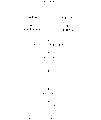
就在上述步骤S102中,对代码字的各符号分配的水印信号进行说明。图3是表示水印信号的一例的说明图。In the above step S102, the watermark signal assigned to each symbol of the codeword will be described. FIG. 3 is an explanatory diagram showing an example of a watermark signal.
设水印信号的宽度与高度分别为Sw、Sh。虽然Sw和Sh也可以不同,但在本实施方式中为了易于说明而设Sw=Sh。长度的单位是像素数,在图3的例子中是Sw=Sh=12。这些信号被打印在纸面上时的大小依赖于水印图像的分辨率,例如如果设水印图像为600dpi(dotperinch:分辨率的单位,每英寸的点数)的图像则图3的水印信号的宽度与高度在打印文档上就为12/600=0.02(英寸)。Let the width and height of the watermark signal be Sw and Sh respectively. Although Sw and Sh may be different, in this embodiment, Sw=Sh is set for ease of description. The unit of the length is the number of pixels, which is Sw=Sh=12 in the example of FIG. 3 . The size of these signals when they are printed on paper depends on the resolution of the watermark image. For example, if the watermark image is an image of 600dpi (dotperinch: the unit of resolution, the number of dots per inch), then the width of the watermark signal in Figure 3 is the same as The height is 12/600=0.02 (inches) on the printed document.
以下,将宽度与高度为Sw、Sh的矩形作为1个信号的单位称为“信号单元”。图3(1)是点间的距离在相对于水平轴arctan(3)(arctan是tan的反函数)的方向上密集,波的传播方向是arctan(-1/3)。以下,将该信号单元称为单元A。图3(2)是点间的距离在相对于水平轴arctan(-3)的方向密集,波的传播方向是arctan(1/3)。以下,将该信号单元称为单元B。Hereinafter, a rectangle whose width and height are Sw and Sh as a unit of one signal is referred to as a "signal unit". Figure 3(1) shows that the distance between points is dense in the direction relative to the horizontal axis arctan(3) (arctan is the inverse function of tan), and the propagation direction of the wave is arctan(-1/3). Hereinafter, this signal unit is referred to as unit A. Figure 3(2) shows that the distance between points is dense in the direction relative to the horizontal axis arctan(-3), and the propagation direction of the wave is arctan(1/3). Hereinafter, this signal unit is referred to as unit B.
图4是从arctan(1/3)的方向观看图3(1)的像素值的变化的断面图。在图4中,排列着点的部分就成为波的最小值的波腹(振幅成为最大的点),未排列着点的部分就成为波的最大值的波腹。FIG. 4 is a cross-sectional view of changes in pixel values in FIG. 3(1) viewed from the direction of arctan (1/3). In FIG. 4 , the portion where the dots are arranged becomes the antinode of the minimum value of the wave (the point where the amplitude becomes maximum), and the portion where the dots are not arranged becomes the antinode of the maximum value of the wave.
另外,由于点被密集排列的区域分别在1单元之中存在2个,故在该例子中每1单元的频率就成为2。由于波的传播方向与点被密集排列的方向相垂直,所以单元A的波相对于水平方向为arctan(-1/3),而单元B的波则为arctan(1/3)。此外,在arctan(a)的方向与acrtan(b)的方向垂直时,a×b=-1。In addition, since there are two areas in which dots are densely arranged in each unit, the frequency per unit is 2 in this example. Since the propagation direction of the wave is perpendicular to the direction in which the points are densely arranged, the wave of unit A is arctan(-1/3) relative to the horizontal direction, while the wave of unit B is arctan(1/3). Also, when the direction of arctan (a) is perpendicular to the direction of acrtan (b), a×b=−1.
在本实施方式中,对用单元A所表达的水印信号分配符号0,对用单元B所表达的水印信号则分配符号1。另外,将它们称为符号单元。In this embodiment, the
在水印信号中除了图3(1)、(2)中所示的以外,例如还考虑如图5(3)~(5)所示那样的点排列。图5(3)是点间的距离在相对于水平轴arctan(1/3)的方向上密集,波的传播方向是arctan(-3)。以下,将该信号单元称为单元C。In the watermark signal, in addition to those shown in FIGS. 3(1) and (2), for example, dot arrangements as shown in FIGS. 5(3) to (5) are also considered. Figure 5(3) shows that the distance between points is dense in the direction relative to the horizontal axis arctan(1/3), and the propagation direction of the wave is arctan(-3). Hereinafter, this signal unit is referred to as unit C.
图5(4)是点间的距离在相对于水平轴arctan(-1/3)的方向上密集,波的传播方向是arctan(3)。以下,将该信号单元称为单元D。图5(5)是点间的距离在相对于水平轴arctan(1)的方向上密集,波的传播方向是arctan(1)。此外,还能够认为图5(5)是点间的距离在相对于水平轴arctan(1)的方向上密集,波的传播方向是arctan(1)。以下,将该信号单元称为单元E。Figure 5(4) shows that the distance between points is dense in the direction relative to the horizontal axis arctan(-1/3), and the propagation direction of the wave is arctan(3). Hereinafter, this signal unit is referred to as unit D. Figure 5(5) shows that the distance between points is dense in the direction relative to the horizontal axis arctan(1), and the propagation direction of the wave is arctan(1). In addition, in Fig. 5 (5), it can be considered that the distance between points is denser in the direction relative to the horizontal axis arctan (1), and the propagation direction of the wave is arctan (1). Hereinafter, this signal unit is referred to as unit E.
这样一来由于除了先前所分配的组合以外,还考虑多个分配符号0与符号1的单元的组合图案,所以还能够将哪个水印信号被分配给哪个符号作为秘密而使得第三者(不正当者)无法简单地译码被嵌入的信号。In this way, in addition to the previously assigned combination, a combination pattern of a plurality of units for assigning
进而,当在图2所示的步骤S102中,将秘密信息以4元代码进行了编码的情况下,例如,还可对单元A分配代码字的符号0,对单元B分配符号1,对单元C分配符号2,对单元D分配符号3。Furthermore, when in step S102 shown in FIG. 2 , when the secret information is coded with a quaternary code, for example, the
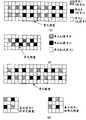
由于在图3、图5所示的水印信号的一例中,使1单元中的点的数目全部相等,所以通过将这些单元无间隙地进行排列,水印图像的外观的浓淡就变得均匀。从而就可看成是在所打印的纸面上持有单一浓度的灰度图像作为背景来进行嵌入。In the example of the watermark signal shown in FIG. 3 and FIG. 5 , the number of dots in one cell is all the same, so by arranging these cells without gaps, the apparent shading of the watermark image becomes uniform. Therefore, it can be regarded as a grayscale image with a single density on the printed paper as the background for embedding.
为了突出这样的效果,例如,在将单元E定义为背景单元(没有分配符号的信号单元),将其无间隙地进行排列以作为水印图像的背景,将符号单元(单元A、单元B)嵌入水印图像的情况下,则替换欲嵌入的位置的背景单元(单元E)与符号单元(单元A、单元B)。In order to highlight such an effect, for example, when unit E is defined as a background unit (a signal unit without assigned symbols), it is arranged without gaps as the background of the watermark image, and the symbol units (unit A, unit B) are embedded in In the case of a watermark image, the background unit (unit E) and the symbol unit (unit A, unit B) at the position to be embedded are replaced.
图6(1)是表示将单元E定义为背景单元,并将其无间隙地排列作为水印图像的背景的情况的说明图。图6(2)表示在图6(1)的背景图像之中嵌入了单元A的一例,图6(3)表示在图6(1)的背景图像之中嵌入了单元B的一例。虽然在本实施方式中,就将背景单元设为水印图像的背景的方法进行说明,但也可以通过仅配置符号单元来生成水印图像。FIG. 6(1) is an explanatory diagram showing a case where cells E are defined as background cells and are arranged without gaps as the background of a watermark image. FIG. 6(2) shows an example of cell A embedded in the background image of FIG. 6(1), and FIG. 6(3) shows an example of cell B embedded in the background image of FIG. 6(1). Although in this embodiment, the method of setting the background unit as the background of the watermark image is described, it is also possible to generate the watermark image by arranging only the symbol units.
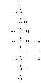
接着,一边参照图7一边就将代码字的一个符号嵌入水印图像的方法进行说明。Next, a method of embedding one symbol of a codeword into a watermark image will be described with reference to FIG. 7 .
图7是表示向水印图像的符号嵌入方法的一例的说明图。这里,作为例子就嵌入“0101”这样的位串的情况进行说明。FIG. 7 is an explanatory diagram showing an example of a method of embedding a symbol into a watermark image. Here, a case where a bit string such as "0101" is embedded will be described as an example.
如图7(1)、(2)所示那样,反复嵌入相同的符号单元。这是为了防止在文档中的字符被重叠于所嵌入的符号单元之上的情况下当信号检测时不被检测出,其中,符号单元的重复数与配置的图案(下面称为单元图案)是任意的。As shown in Fig. 7(1) and (2), the same symbol unit is repeatedly embedded. This is to prevent a character in a document from being undetected when a signal is detected in a case where a character in a document is superimposed on an embedded symbol unit, wherein the number of repetitions of a symbol unit and a pattern of configuration (hereinafter referred to as a unit pattern) are Arbitrary.
即,作为单元图案的一例,能够如图7(1)那样将重复数设成4(在1个单元图案中存在4个符号单元),或者如图7(2)那样将重复数设成2(在1个单元图案中存在2个符号单元),或者也可以将重复数设成1(在1个单元图案中仅存在1个符号单元)。That is, as an example of a unit pattern, the number of repetitions can be set to 4 (there are 4 symbol units in one unit pattern) as shown in FIG. 7(1), or the number of repetitions can be set to 2 as shown in FIG. 7(2). (two symbol units exist in one unit pattern), or the repetition number may be set to 1 (only one symbol unit exists in one unit pattern).
另外,虽然图7(1)、(2)是对1个符号单元赋予1个符号,但也可以如图7(3)那样对符号单元的配置图案赋予符号。In addition, although one symbol is assigned to one symbol unit in FIGS. 7(1) and (2), symbols may be assigned to an arrangement pattern of the symbol units as in FIG. 7(3).
能够在一页量的水印图像之中嵌入多少位的信息量依赖于信号单元的大小、单元图案的大小以及文档图像的大小。在文档图像的水平方向和垂直方向上嵌入多少信号,既可以作为已知来进行信号检测,也可以根据从输入装置所输入的图像的大小和信号单元的大小反过来计算。How many bits of information can be embedded in a watermark image of one page depends on the size of a signal unit, the size of a unit pattern, and the size of a document image. How many signals are embedded in the horizontal direction and vertical direction of the document image can be used as a known signal for signal detection, or can be reversely calculated according to the size of the image input from the input device and the size of the signal unit.
设在1页量的水印图像的水平方向上嵌入Pw个,在垂直方向上嵌入Ph个单元图案,将图像中的任意位置的单元图案表达为U(x,y),x=1~Pw,y=1~Ph,将U(x,y)称为“单元图案矩阵”。另外,将能够嵌入一页的位数称为“嵌入位数”。嵌入位数是Pw×Ph。It is assumed that Pw unit patterns are embedded in the horizontal direction of the watermark image of 1 page, and Ph unit patterns are embedded in the vertical direction, and the unit pattern at any position in the image is expressed as U(x, y), x=1~Pw, y=1 to Ph, and U(x, y) is called "unit pattern matrix". In addition, the number of bits that can be embedded in one page is referred to as "embedded number of bits". The number of embedded bits is Pw×Ph.
图8所示的是将秘密信息16嵌入水印图像的方法的流程图。这里就在1张(1页量)的水印图像上反复嵌入相同信息的情况进行说明。这是因为通过反复嵌入相同信息,即便在使水印图像与文档图像重合时1个单元图案全体被涂满等使得嵌入信息消失这样的情况下,也可取出所嵌入的信息。FIG. 8 is a flowchart of a method for embedding
首先,将秘密信息16变换成N元代码(步骤S201)。与图2的步骤S101相同。在下面,将经过编码的数据称为数据代码,将通过单元图案的组合来表达数据代码的单元称为数据代码单元Du。First, the
接着,从数据代码的代码长度(这里是位数)和嵌入位数计算能够在1张图像上反复多少次嵌入数据代码单元(步骤S202)。在本实施方式中,设为将数据代码的代码长度数据插入单元图案矩阵的第1行。也可以将数据代码的代码长度设为固定长度而不在水印图像中嵌入代码长度数据。Next, it is calculated from the code length of the data code (here, the number of bits) and the number of embedding bits, how many times the data code unit can be repeatedly embedded in one image (step S202). In this embodiment, it is assumed that the code length data of the data code is inserted into the first row of the unit pattern matrix. It is also possible to set the code length of the data code to a fixed length without embedding the code length data in the watermark image.
嵌入数据代码单元的次数Dn,设数据代码长度为Cn用以下公式来进行计算。The number of times Dn to embed the data code unit is calculated by the following formula assuming that the data code length is Cn.

[A]是不超过A的最大整数[A] is the largest integer not exceeding A
在这里若设剩余为Rn(Rn=Cn-(Pw×(Ph-1)))就在单元图案矩阵中嵌入Dn次的数据代码单元以及与数据代码的开头Rn位相当的单元图案。但是,剩余部分的Rn位未必一定嵌入也可以。Here, if the remainder is Rn (Rn=Cn-(Pw×(Ph-1))), Dn times of data code units and a unit pattern corresponding to the first Rn bits of the data code are embedded in the unit pattern matrix. However, the remaining Rn bits may not necessarily be embedded.
在图9的说明中,设单元图案矩阵的大小为9×11(11行9列),设数据代码长为12(图中加上0~11的编号的表示数据代码的各代码字)。In the description of FIG. 9, the size of the unit pattern matrix is set to 9×11 (11 rows and 9 columns), and the data code length is set to 12 (the code words representing the data codes are numbered from 0 to 11 in the figure).
接着,在单元图案矩阵的第1行嵌入代码长度数据(步骤S203)。虽然在图9的例子中说明的是用9位数据来表达代码长度仅嵌入1次的例子,但在单元图案矩阵的宽度Pw非常大的情况下,也能够与数据代码同样反复嵌入代码长度数据。Next, code length data is embedded in the first row of the unit pattern matrix (step S203). In the example of FIG. 9, an example in which the code length is expressed by 9-bit data is embedded only once is described, but when the width Pw of the unit pattern matrix is very large, it is also possible to repeatedly embed the code length data in the same way as the data code. .
进而,在单元图案矩阵的第2行以后,反复嵌入数据代码单元(步骤S204)。如在图9中所示那样从数据代码的MSB(most significantbit)或者LSB(least significant bit)起按顺序在行方向上进行嵌入。在图9的例子中表示嵌入数据代码单元7次,以及嵌入数据代码的开头6位的例子。Furthermore, data code cells are repeatedly embedded in the second and subsequent rows of the cell pattern matrix (step S204). Embedding is performed sequentially in the row direction from MSB (most significant bit) or LSB (least significant bit) of the data code as shown in FIG. 9 . In the example of FIG. 9, an example of embedding the
数据的嵌入方法既可以如图9那样在行方向上成为连续来进行嵌入,也可以在列方向上成为连续来进行嵌入。The method of embedding data may be continuous in the row direction as shown in FIG. 9 , or may be continuous in the column direction.
以上,就水印图像形成部12中的水印图像进行了说明。接着,就水印信息嵌入装置10的有水印文档图像合成部13进行说明。The watermark image in the watermark
(有水印文档图像合成部13)(with watermark document image synthesis unit 13)
在有水印文档图像合成部13中将用文档图像形成部11所创建的文档图像与用水印图像形成部12所创建的水印图像重叠起来。有水印文档图像的各像素的值通过文档图像与水印图像的相对应的像素值的逻辑乘法运算(AND)来进行计算。即,如果文档图像与水印图像的哪一个为0(黑),则有水印文档图像的像素值为0(黑),除此以外就为1(白)。The document image created by the document
图10是表示有水印文档图像的一例的说明图。图11是扩大图10的一部分来表示的说明图。这里,单元图案使用了图7(1)的图案。有水印文档图像由输出设备14进行输出。FIG. 10 is an explanatory diagram showing an example of a watermarked document image. FIG. 11 is an explanatory diagram showing an enlarged part of FIG. 10 . Here, the pattern of FIG. 7(1) was used as a unit pattern. The watermarked document image is output by the
以上,就水印信息嵌入装置10的动作进行了说明。The operation of the watermark
接着,一边参照图1以及图12~图19,一边就水印信息检测装置30的动作进行说明。Next, the operation of the watermark information detection device 30 will be described with reference to FIG. 1 and FIGS. 12 to 19 .
(水印检测部32)(Watermark detection unit 32)
图12是表示水印检测部32的处理流程的流程图。FIG. 12 is a flowchart showing the processing flow of the
首先,通过扫描器等输入设备31将有水印文档图像输入到计算机的存储器等(步骤S301)。将该图像称为输入图像。输入图像是多值图像,在下面设为256灰度等级的灰度图像来进行说明。另外虽然输入图像的分辨率(在输入设备31中读入时的分辨率)可以与上述水印信息嵌入装置10所创建的有水印文档图像不同,但在这里设为与上述水印信息嵌入装置10所创建的图像相同的分辨率来进行说明。另外,就1个单元图案由1个符号单元构成的情况进行说明。First, a watermarked document image is input to a memory of a computer or the like through an
<信号检测滤波步骤(步骤S310)><Signal detection filtering step (step S310)>
在步骤S310中对输入图像整体进行滤波处理,并进行滤波器输出值的计算和滤波器输出值的比较。滤波器输出值的计算利用以下所示的被称为伽柏滤波器(ガボ一ルフイルタ)的滤波器,在输入图像的全像素中通过滤波器与图像间的卷积(コンボリユ一シヨン)来进行计算。In step S310, filter processing is performed on the entire input image, and filter output value calculation and filter output value comparison are performed. The calculation of the output value of the filter is performed by convolution between the filter and the image in all pixels of the input image using a filter called the Gabor filter shown below calculate.
以下表示伽柏滤波器G(x,y),x=0~gw-1,y=0~gh-1。gw、gh是滤波器的大小,在这里与上述水印信息嵌入装置10所嵌入的信号单元大小相同。The Gabor filter G(x, y) is shown below, where x=0 to gw-1 and y=0 to gh-1. gw and gh are the size of the filter, which is the same as the size of the signal unit embedded by the above-mentioned watermark
i:虚数单位i: imaginary unit
x=0~gw-1,y=0~gh-1,x0=gw/2,y0=gh/2x=0~gw-1, y=0~gh-1, x0=gw/2, y0=gh/2
A:水平方向的影响范围,B:垂直方向的影响范围A: the range of influence in the horizontal direction, B: the range of influence in the vertical direction
tan-1(u/v):波的方向,
输入图像中的任意位置上的滤波器输出值通过滤波器与图像间的卷积来进行计算。在伽柏滤波器的情况下由于存在实数滤波器与虚数滤波器(虚数滤波器是与实数滤波器错开半波长相位的滤波器),所以将它们的2乘平均值设为滤波器输出值。例如,若设某像素(x,y)中的亮度值与滤波器A的实数滤波器的卷积为Rc,与虚数滤波器的卷积为Ic,则滤波器输出值F(A,x,y)用以下公式来进行计算。The filter output value at any position in the input image is computed by convolving the filter with the image. In the case of the Gabor filter, since there are a real filter and an imaginary filter (the imaginary filter is a filter with a half-wavelength phase shift from the real filter), their 2-multiplied average value is used as the filter output value. For example, if the convolution of the brightness value in a certain pixel (x, y) with the real filter of filter A is Rc, and the convolution with the imaginary filter is Ic, then the filter output value F(A, x, y) Use the following formula to calculate.
如上述那样在对与各信号单元相对应的所有种类的滤波器计算了滤波器输出值后,在各像素中比较如上述那样所计算的滤波器输出值,将其最大值F(x,y)作为滤波器输出值矩阵来进行存储。另外,将对应于值最大的滤波器的信号单元的编号作为滤波器种类矩阵来进行存储(图13)。具体而言,当在某像素(x,y)中,F(A,x,y)>F(B,x,y)的情况下,设定F(A,x,y)作为滤波器输出值矩阵的(x,y)的值,作为滤波器种类矩阵的(x,y)的值设定表示信号单元A的“0”(在本实施方式中,设信号单元A、B的编号为“0”、“1”)。After calculating the filter output values for all types of filters corresponding to each signal unit as described above, the filter output values calculated as described above are compared in each pixel, and the maximum value F(x, y ) is stored as a matrix of filter output values. In addition, the signal unit number corresponding to the filter with the largest value is stored as a filter type matrix ( FIG. 13 ). Specifically, when F(A, x, y) > F(B, x, y) in a certain pixel (x, y), set F(A, x, y) as the filter output The value of (x, y) in the value matrix is set as the value of (x, y) in the filter type matrix to indicate "0" representing the signal unit A (in this embodiment, the numbers of the signal units A and B are set to "0", "1").
此外,虽然在本实施方式中滤波器的个数为2,但即便在滤波器的个数比其多的情况下,同样地存储多个的滤波器输出值的最大值和对应于此时的滤波器的信号单元编号即可。In addition, although the number of filters is 2 in this embodiment, even if the number of filters is larger than that, the maximum values of the output values of the filters and the corresponding The signal unit number of the filter is sufficient.
<信号位置搜索步骤(步骤S320)><Signal position search step (step S320)>
在步骤S320中,利用在步骤S310中所得到的滤波器输出值矩阵来决定信号单元的位置。具体而言,首先,若设信号单元的大小按Sh×Sw来构成,则创建格子点的垂直方向的间隔为Sh、水平方向的间隔为Sw、格子点的个数为Nh×Nw的信号位置搜索模板(图14)。这样所创建的模板的大小就为Th(Sh*Nh)×Tw(Sw*Nw),在Nh、Nw中为了搜索信号单元位置而使用最佳的值即可。In step S320, the position of the signal unit is determined by using the filter output value matrix obtained in step S310. Specifically, first, if the size of the signal unit is configured as Sh×Sw, then create a signal position where the vertical interval of the grid points is Sh, the horizontal interval is Sw, and the number of grid points is Nh×Nw Search for templates (Figure 14). In this way, the size of the created template is Th(Sh*Nh)×Tw(Sw*Nw), and it is only necessary to use the best value among Nh and Nw for searching the position of the signal unit.
接着,按模板的大小逐个分割滤波器输出值矩阵。进而,在各分割区域中对相邻接的区域的信号单元不重复的范围(水平方向±Sw/2,垂直方向±Sh/2,)内一边在滤波器输出值矩阵上以像素单位使模板移动,一边利用以下公式求解模板格子点上的滤波器输出值矩阵值F(x,y)的总和V(图14),将该总和最大的模板的格子点设为该区域的信号单元的位置。Next, the matrix of filter output values is divided one by one by the size of the template. Furthermore, within the range (horizontal direction ±Sw/2, vertical direction ±Sh/2,) where the signal units of adjacent regions do not overlap in each divided region, the template is made in units of pixels on the filter output value matrix. Move, while using the following formula to solve the sum V (Figure 14) of the filter output value matrix value F (x, y) on the grid point of the template, and set the grid point of the template with the largest sum to the position of the signal unit in this area .
Xs-Sw/2<x<Xe+Sw/2,Ys-Sh/2+<y<Ye+Sh/2Xs-Sw/2<x<Xe+Sw/2, Ys-Sh/2+<y<Ye+Sh/2
(Xs,Ys):分割区域的左上坐标,(Xe,Ye):分割区域的右下坐标(Xs, Ys): the upper left coordinates of the segmented area, (Xe, Ye): the lower right coordinates of the segmented area
上述的例子是在步骤S310中对全部像素求解滤波器输出值的情况,在进行滤波之际,还能够仅对某一定间隔的像素进行滤波。例如,在每隔2像素进行滤波的情况下,将上述的信号位置搜索模板的格子点的间隔设为1/2即可。The above-mentioned example is a case where the filter output values are obtained for all pixels in step S310, but it is also possible to perform filtering only for pixels at a certain interval when filtering is performed. For example, in the case of performing filtering every 2 pixels, the interval of the grid points of the above-mentioned signal position search template may be set to 1/2.
<信号符号决定步骤(步骤S330)><Signal symbol determination step (step S330)>
在步骤S330中,通过参照在步骤S320中所决定的信号单元位置的滤波器种类矩阵的值(对应于滤波器的信号单元编号),来决定信号单元是A还是B。In step S330, whether the signal unit is A or B is determined by referring to the value of the filter type matrix (corresponding to the signal unit number of the filter) at the signal unit position determined in step S320.
如上述那样,将所决定的信号单元的判定结果作为符号矩阵来进行存储。As described above, the determination result of the determined signal unit is stored as a symbol matrix.
<信号边界决定步骤(步骤S340)><Signal Boundary Determination Step (Step S340)>
由于在步骤S320中,不论信号单元是否嵌入都对图像全部面进行滤波处理,所以就有必要决定在哪个部分嵌入了信号单元。因而,在步骤S340中,通过从符号矩阵搜索在嵌入信号单元预先确定的图案来求解信号边界。Since in step S320, regardless of whether the signal unit is embedded or not, the filtering process is performed on the entire surface of the image, so it is necessary to determine in which part the signal unit is embedded. Thus, in step S340, the signal boundary is solved by searching the pattern predetermined in the embedded signal unit from the symbol matrix.
例如若设在信号单元所嵌入的边界一定嵌入信号单元A,则沿在步骤S330中所决定的符号矩阵的横方向对信号单元A的数目进行计数,将从中心起在上下信号单元A的个数最多的位置分别设为信号边界的上端/下端。在图15的例子中,由于符号矩阵中的信号单元A用“黑”(值为“0”)来表达,所以通过对符号矩阵的黑像素数进行计数,就能够对信号单元A的数目进行计数,并能够根据该度数分布求解出信号边界的上端/下端。左端/右端也仅仅是对单元A的个数进行计数的方向不同而已,能够同样地进行求解。For example, if the boundary where the signal unit is embedded must be embedded with the signal unit A, then the number of the signal unit A is counted along the horizontal direction of the symbol matrix determined in step S330, and the numbers of the upper and lower signal units A from the center are counted. The position with the largest number is set to the upper end/lower end of the signal boundary, respectively. In the example of Fig. 15, since the signal unit A in the symbol matrix is expressed by "black" (value "0"), by counting the number of black pixels in the symbol matrix, the number of the signal unit A can be calculated Count, and be able to solve for the upper/lower ends of the signal boundary from this degree distribution. The left end and the right end are only different in the direction of counting the number of cells A, and can be solved in the same way.
为了求解信号边界并不限于上述方法,只要预先在嵌入侧和检测侧决定好能够从符号矩阵进行搜索的图案即可。Finding the signal boundary is not limited to the above-mentioned method, and it is only necessary to determine a pattern that can be searched from the symbol matrix in advance on the embedding side and the detection side.
再次返回到图12的流程图,就以后的步骤S305进行说明。在步骤S305中,在符号矩阵之中从相当于信号边界内部的部分复原原来的信息。此外,在本实施方式中,由于一个单元图案用一个符号单元来构成,所以单元图案矩阵就与符号矩阵等价。Returning to the flowchart of FIG. 12 again, the subsequent step S305 will be described. In step S305, the original information is restored from the part corresponding to the inside of the signal boundary in the symbol matrix. In addition, in this embodiment, since one unit pattern is constituted by one symbol unit, the unit pattern matrix is equivalent to the symbol matrix.
<信息解密步骤(步骤S305)><Information decryption step (step S305)>
图16是表示信息复原的一例的说明图。信息复原的步骤如下面那样。FIG. 16 is an explanatory diagram showing an example of information restoration. The procedure for restoring information is as follows.
(1)对各单元图案中所嵌入的符号进行检测(图16(1))。(1) Detect the symbols embedded in each unit pattern (FIG. 16(1)).
(2)连结符号以复原数据代码(图16(2))。(2) Connect the symbols to restore the data code (Fig. 16(2)).
(3)对数据代码进行解密并取出所嵌入的信息(图16(3))。(3) Decrypt the data code and take out the embedded information (Fig. 16(3)).
图17~图19是表示数据代码的复原方法的一例的说明图。复原方法基本上就是图8的逆处理。17 to 19 are explanatory diagrams showing an example of a restoration method of a data code. The recovery method is basically the inverse process of FIG. 8 .
首先,从单元图案矩阵的第1行取出代码长度数据部分,以获得所嵌入的数据代码的代码长度(步骤S401)。First, the code length data part is taken out from the first row of the unit pattern matrix to obtain the code length of the embedded data code (step S401).
接着,以单元图案矩阵的大小与在步骤S401中所得到的数据代码的代码长度为基础计算嵌入了数据代码单元的次数Dn以及剩余Rn(步骤S402)。Next, the number Dn of embedded data code units and the remainder Rn are calculated based on the size of the unit pattern matrix and the code length of the data code obtained in step S401 (step S402).
接着,从单元图案矩阵的第2行以后起以与步骤S203相反的方法取出数据代码单元(步骤S403)。在图18的例子中是从U(1,2)(2行1列)起按顺序对12个的图案单元逐个进行分解(U(1,2)~U(3,3)、U(4,3)~U(6,4),···)。由于是Dn =7、Rn=6,所以12个图案单元(数据代码单元)被取出7次,作为剩余6个(相当于数据代码单元的高位6个)的单元图案(U(4,11)~U(9,11))被取出。Next, data code cells are taken out from the second and subsequent rows of the cell pattern matrix in the reverse method of step S203 (step S403). In the example of FIG. 18, 12 pattern units are decomposed one by one from U(1,2) (2 rows and 1 column) (U(1,2)~U(3,3), U(4 ,3)~U(6,4),...). Owing to be Dn=7, Rn=6, so 12 pattern units (data code unit) are taken out 7 times, as the unit pattern (U(4,11) of remaining 6 (equivalent to
接着,通过对在步骤S403中所取出的数据代码单元进行位可靠度运算,来重构所嵌入的数据代码(步骤S404)。以下,就位可靠度运算进行说明。Next, the embedded data code is reconstructed by performing bit reliability calculation on the data code unit extracted in step S403 (step S404). Next, the bit reliability calculation will be described.
如图19那样设从单元图案矩阵的第2行第1列起最初所取出的数据代码单元为Du(1,1)~Du(12,1),并顺次表记为Du(1,2)~Du(12,2),···。另外,设剩余部分为Du(1,8)~Du(6,8)。位可靠度运算就是对各数据代码单元的要素逐个采取多数判决等以决定数据代码的各符号的值。由此,即便在因与字符区域重叠或纸面污垢等原因而无法从任意的数据代码单元中的任意单元进行正确的信号检测的情况(位取反错误等)下也能够最终正确地复原数据代码。As shown in Figure 19, it is assumed that the data code units initially taken out from the second row and the first column of the unit pattern matrix are Du(1,1)-Du(12,1), and are expressed as Du(1,2 in sequence. )~Du(12,2),... In addition, let the remainder be Du(1,8)-Du(6,8). The bit reliability calculation is to determine the value of each symbol of the data code by taking a majority decision on the elements of each data code unit one by one. As a result, even when correct signal detection cannot be performed from any unit of any data code unit due to reasons such as overlapping with the character area or dirt on the paper surface (bit inversion error, etc.), the data can finally be correctly restored code.
具体而言,例如数据代码的第1位,在Du(1,1),Du(1,2),···,Du(1,8)的信号检测结果为1一方较多的情况下判定为1,在为0一方较多的情况下则判定为0。同样数据代码的第2位通过根据Du(2,1),Du(2,2),···,Du(2,8)的信号检测结果的多数判决来进行判定,数据代码的第12位通过根据Du(12,1),Du(12,2),···,Du(12,7)(因Du(12,8)不存在故到Du(12,7)为止)的信号检测结果的多数判决来进行判定。Specifically, for example, the first bit of the data code is judged when the signal detection result of Du(1, 1), Du(1, 2), ..., Du(1, 8) is 1 or more It is 1, and it is judged as 0 when there are more 0 parties. Similarly, the second bit of the data code is judged by the majority decision based on the signal detection results of Du (2, 1), Du (2, 2), ..., Du (2, 8), and the 12th bit of the data code According to the signal detection results of Du(12,1), Du(12,2),..., Du(12,7) (Du(12,8) does not exist until Du(12,7)) majority decision to make a decision.
虽然在这里就反复嵌入数据代码的情况进行了说明,但通过在对数据进行编码之际使用纠错代码等,也能够实现诸如不进行数据代码单元的重复这样的方法。Here, the case of repeatedly embedding data codes has been described, but it is also possible to realize a method in which data code units are not repeated by using an error correction code or the like when encoding data.
(第1实施方式的效果)(Effect of the first embodiment)
如以上说明那样,根据本实施方式,由于能够对输入图像全部面实施滤波处理,并利用信号位置搜索模板来求解信号单元的位置以使得滤波器输出值的总和成为最大,所以即便在因用纸的歪斜等而使图像伸缩等情况下,也能够正确地检测信号单元的位置,能够从带有秘密信息的文档准确地检测出秘密信息。As described above, according to the present embodiment, since the filtering process can be performed on the entire surface of the input image, and the position of the signal unit can be obtained by using the signal position search template so that the sum of the filter output values can be maximized, even in different paper It is possible to accurately detect the position of the signal unit even when the image is stretched or contracted due to the distortion of the image, and the secret information can be accurately detected from the document with the secret information.
(第2实施方式)(second embodiment)
在上述的第1实施方式中,在按信号位置搜索模板的大小将滤波器输出值矩阵分割后的各分割区域上搜索信号位置。相对于此,在第2实施方式中,在搜索信号位置之际,将最初用信号位置搜索模板来搜索信号位置的位置设定成用纸中央等能够稳定求解信号位置的位置。之后,在该初始位置搜索信号位置,如果信号位置能够决定,就基于该决定了的信号位置,顺次决定周围的信号位置。In the above-described first embodiment, the signal position is searched for each of the divided regions in which the filter output value matrix is divided according to the size of the signal position search template. On the other hand, in the second embodiment, when searching for the signal position, the position where the signal position is first searched using the signal position search template is set to a position such as the center of the paper where the signal position can be obtained stably. After that, the signal position is searched at the initial position, and if the signal position can be determined, the surrounding signal positions are sequentially determined based on the determined signal position.
关于本实施方式中的水印信息嵌入装置10以及水印信息检测装置20的构成,由于与上述第1实施方式实质上相同所以省略重复说明。以下,就本实施方式的动作进行说明。The configurations of the watermark
图20中表示第2实施方式的流程图。在第1实施方式中取代信号位置搜索步骤(步骤S320)而增加了初始信号位置搜索步骤(步骤S350)和逐次信号位置搜索步骤(步骤S360)。以下,仅说明不同的部分。FIG. 20 shows a flowchart of the second embodiment. In the first embodiment, an initial signal position search step (step S350 ) and a successive signal position search step (step S360 ) are added instead of the signal position search step (step S320 ). Hereinafter, only the different parts will be described.
<初始信号位置搜索步骤(步骤S350)><Initial signal position search step (step S350)>
在步骤S350中,决定信号位置搜索模板的初始位置。将要决定的初始位置设定成能够精度良好地检测信号单元的位置。例如既可以是输入图像的中央位置,也可以为了回避包含输入图像的字符等的区域而决定成相当于字符的比较暗的像素(亮度值较小的像素)的分布最稀疏的位置。In step S350, an initial position of the signal position search template is determined. The initial position to be determined is set to a position where the signal unit can be detected with high accuracy. For example, it may be the central position of the input image, or a position where relatively dark pixels (pixels with small luminance values) corresponding to characters are most sparsely distributed in order to avoid regions including characters of the input image.
<逐次信号位置搜索步骤(步骤S360)><Sequential signal position search step (step S360)>
在步骤S360中,以步骤S350中所决定的信号位置搜索模板的初始位置为基点,按顺序来决定相邻接的模板的位置。首先,在初始位置以与第1实施方式的信号位置搜索步骤(步骤S320)相同的方法决定一个模板的位置。接下来将所决定的模板的上下或者左右相邻接的区域设定成下一模板搜索位置,进行下一模板位置的搜索。反复相同的处理来决定输入图像全体的模板位置(图21)。相邻接的模板位置的搜索顺序,例如在第1象限中沿x轴正方向搜索至图像末端,接下来沿y轴正方向前进一个区域同样沿x轴正方向进行搜索。接下来在第2,第3,第4象限也仅仅是搜索方向不同而已能够同样地进行搜索。In step S360, taking the initial position of the signal position search template determined in step S350 as a base point, the positions of adjacent templates are sequentially determined. First, the position of one template is determined at the initial position by the same method as the signal position search step (step S320 ) of the first embodiment. Next, the upper, lower or left and right adjacent areas of the determined template are set as the next template search position, and the search for the next template position is performed. The same process is repeated to determine the template position of the entire input image (FIG. 21). The search sequence of adjacent template positions, for example, in the first quadrant along the positive direction of the x-axis is searched to the end of the image, and then a region is advanced along the positive direction of the y-axis to search along the positive direction of the x-axis. Next, in the 2nd, 3rd, and 4th quadrants, only the search direction is different and the same search can be performed.
(第2实施方式的效果)(Effect of the second embodiment)
如以上说明那样,根据本实施方式,能够从某信号位置搜索模板的邻接位置起进行下一模板的搜索。即使例如因图像的旋转等而在图像的末端方向歪斜累积的情况那样,在对于初始位置持有信号单元的大小以上的歪斜的情况下也能够恰当地检测信号单元。As described above, according to the present embodiment, it is possible to search for the next template from a position adjacent to a certain signal position search template. Even if, for example, distortion accumulates in the direction of the end of the image due to image rotation or the like, the signal unit can be properly detected when there is a distortion equal to or greater than the signal unit at the initial position.
(第3实施方式)(third embodiment)
在上述的第1实施方式中,按信号位置搜索模板的大小来分割滤波器输出值矩阵,仅参照信号位置搜索模板内部的滤波器输出值来搜索信号位置。相对于此,在第3实施方式中,创建包含信号位置搜索模板、大小比其大的扩大模板,使用还能够参照存在于分割后的区域的周围的滤波器输出值的扩大模板来进行信号位置的搜索。In the first embodiment described above, the filter output value matrix is divided according to the size of the signal position search template, and the signal position is searched by referring only to the filter output values inside the signal position search template. On the other hand, in the third embodiment, an expansion template having a larger size than the signal position search template is created, and the signal position is performed using the expansion template that can also refer to filter output values existing around the divided region. search.
关于本实施方式中的水印信息嵌入装置10以及水印信息检测装置20的构成,由于与上述第1实施方式实质上相同所以省略重复说明。以下,就本实施方式的动作进行说明。The configurations of the watermark
图22中表示第3实施方式的流程图。在第1实施方式中取代信号位置搜索步骤(步骤S320)而增加了扩大信号位置搜索步骤(步骤S370)。以下,仅说明不同部分。FIG. 22 shows a flowchart of the third embodiment. In the first embodiment, an expanded signal position search step (step S370 ) is added instead of the signal position search step (step S320 ). Hereinafter, only different parts will be described.
<扩大信号位置搜索步骤(步骤S370)><Extended signal position search step (step S370)>
在步骤S370中,以与第1实施方式的信号位置搜索步骤(步骤S320)相同的方法创建信号位置搜索模板,进而创建更大的扩大模板并在内部配置信号位置搜索模板(图23)。设扩大模板持有与信号位置搜索模板相同的格子点,格子点的个数为Mh×Mw(Mh≥Nh,Mw≥Nw)。所创建的扩大模板的大小就为Eh(Sh*Mh)×Ew(Sw*Mw)。内部的信号位置搜索模板配置在中央,与第1实施方式的信号位置搜索步骤(步骤S320)同样按信号位置搜索模板的大小来分割滤波器输出值矩阵。In step S370, a signal position search template is created in the same way as the signal position search step (step S320) of the first embodiment, and a larger enlarged template is created and a signal position search template is arranged inside (FIG. 23). It is assumed that the expanded template holds the same grid points as the signal location search template, and the number of grid points is Mh×Mw (Mh≥Nh, Mw≥Nw). The size of the enlarged template created is then Eh(Sh*Mh)×Ew(Sw*Mw). The internal signal position search template is arranged at the center, and the filter output value matrix is divided according to the size of the signal position search template similarly to the signal position search step (step S320 ) of the first embodiment.
进而,在内部的信号位置搜索模板对相邻接的区域的信号单元不重复的范围内一边以像素单位使扩大模板移动,一边求解格子点上的滤波器输出值矩阵值F(x,y)的总和W,并决定该总和W最大的扩大模板的位置。从所决定的扩大模板求解内部的信号位置搜索模板的位置,将该格子点设为该分割区域的信号单元位置。Furthermore, the filter output value matrix value F(x, y) at the grid points is obtained while moving the expansion template in units of pixels within a range in which the internal signal position search template does not overlap the signal units of adjacent regions. The sum W, and determine the position of the enlarged template with the largest sum W. The position of the template is searched from the signal position inside the determined expanded template solution, and the grid point is set as the signal unit position of the divided region.
Mh=v1+v0+1,Mw=u1-u0+1Mh=v1+v0+1, Mw=u1-
(u0,v0):以扩大模板的左上格子点为原点时的信号位置决定模板的左上格子点的坐标(u0, v0): The coordinates of the upper left grid point of the template are determined by the signal position when the upper left grid point of the enlarged template is taken as the origin
Xs-Sw/2<x<Xe+Sw/2,Ys-Sh/2+<y<Ye+Sh/2Xs-Sw/2<x<Xe+Sw/2, Ys-Sh/2+<y<Ye+Sh/2
(Xs,Ys):分割区域的左上坐标,(Xe,Ye):分割区域的右下坐标(第3实施方式的效果)(Xs, Ys): upper left coordinates of the divided area, (Xe, Ye): lower right coordinates of the divided area (effect of the third embodiment)
如以上说明那样,根据本实施方式,除分割区域的滤波器输出值外还可使用周围的区域的滤波器输出值来进行信号位置的确定。在例如分割区域中包含输入图像的字符区域那样的分割区域内的滤波器输出值无法充分获得的情况下也能够恰当地进行信号检测。As described above, according to the present embodiment, the signal position can be specified using the filter output values of the surrounding regions in addition to the filter output values of the divided regions. Signal detection can also be appropriately performed when, for example, a filter output value in a segmented area including a character area of an input image cannot be obtained sufficiently.
(第4实施方式)(fourth embodiment)
在上述的第1实施方式中,使用信号位置搜索模板来决定信号单元的位置,之后从所取得的符号矩阵求解信号边界。相对于此,在第4实施方式中,除了秘密信息以外信号单元的水平/垂直方向的个数也同时预先进行嵌入,在决定了信号单元的位置以及信号边界之后,如果需要就检测所嵌入的上述的信息,并依照该信息来修正信号单元位置。In the first embodiment described above, the position of the signal unit is determined using the signal position search template, and then the signal boundary is obtained from the obtained symbol matrix. On the other hand, in the fourth embodiment, in addition to secret information, the number of signal units in the horizontal/vertical direction is also embedded in advance at the same time, and after the position of the signal unit and the signal boundary are determined, the embedded information is detected if necessary. The above information, and correct the position of the signal unit according to the information.
关于本实施方式中的水印信息嵌入装置10以及水印信息检测装置20的构成,由于与上述第1实施方式实质上相同所以省略重复说明。以下,就本实施方式的动作进行说明。The configurations of the watermark
图24是第4实施方式中的水印检测部的流程图。是在第1实施方式中具有信号数解码步骤(步骤S375)与信号位置修正步骤(步骤S380)的流程图。以下,就修正信号单元位置的方法进行说明。Fig. 24 is a flowchart of a watermark detection unit in the fourth embodiment. It is a flowchart including a signal number decoding step (step S375 ) and a signal position correction step (step S380 ) in the first embodiment. Hereinafter, the method of correcting the position of the signal unit will be described.
<信号数解码步骤(步骤S375)><Signal number decoding step (step S375)>
在步骤S375中,与第1实施方式的信息解密步骤(步骤S305)同样,基于在信号位置搜索(步骤S320)与信号边界决定(步骤S340)中所决定的信号边界来解密信息,除了秘密信息以外还从所解码的数据检测出预先所嵌入的信号单元的水平/垂直方向的个数。该信息被嵌入的地点只要是能够可靠地进行检测的位置、例如可稳定进行检测的信号边界的紧靠内侧等则在哪里均可。进而,在编码/解码之际也使用利用纠错代码等任意的方法来进行编码,并使用分配给各符号的信号单元嵌入上述的位置即可。In step S375, similar to the information decryption step (step S305) of the first embodiment, the information is decrypted based on the signal boundary determined in the signal position search (step S320) and the signal boundary determination (step S340), except for the secret information In addition, the number of the horizontal/vertical direction of the pre-embedded signal unit is also detected from the decoded data. The place where this information is embedded may be anywhere as long as it is a position that can be reliably detected, for example, immediately inside a signal boundary where stable detection can be performed. Furthermore, at the time of encoding/decoding, arbitrary methods such as error correction codes may be used for encoding, and the above-mentioned positions may be embedded using signal units allocated to each symbol.
<信号位置修正步骤(步骤S380)><Signal Position Correction Step (Step S380)>
在图25中表示信号位置修正的处理说明图。FIG. 25 shows a processing explanatory diagram of signal position correction.
在步骤S380中,首先从在信号位置搜索步骤(步骤S320)中所求出的信号单元位置和在信号边界决定步骤(步骤S340)中所求出信号边界,求解信号单元的水平/垂直方向的个数。之后,比较该个数与在步骤S375中所检测出的信号单元数,如果不一致就修正信号单元的位置。In step S380, first from the signal unit position obtained in the signal position search step (step S320) and the signal boundary obtained in the signal boundary determination step (step S340), the horizontal/vertical direction of the signal unit is solved. number. Thereafter, this number is compared with the number of signal units detected in step S375, and if they do not match, the positions of the signal units are corrected.
作为进行修正的方法,例如,如果水平方向的个数与所嵌入的信息相比较较少则如图25那样求解检测出的信号单元位置的各水平方向的间隔,在间隔最大的信号单元位置的中点追加新的信号单元位置。在如上述那样追加信号单元位置经过修正的信号单元的个数少于抽取出的信号单元的个数的情况下,反复进行该处理直到与检测出的信号单元的个数相等为止。反之如果较多,则从信号位置单元位置的水平方向的间隔最小之处起按顺序删除一个信号单元的位置。垂直方向的信号单元位置的修正也可与水平方向同样进行。As a method of correction, for example, if the number in the horizontal direction is relatively small compared with the embedded information, the intervals in each horizontal direction of the detected signal unit positions are solved as shown in Figure 25, and the signal unit positions with the largest interval Append the new signal unit position at the midpoint. When the number of signal cells whose positions are corrected by adding signal cells is smaller than the number of extracted signal cells as described above, this process is repeated until it is equal to the number of detected signal cells. On the contrary, if there are more, the position of one signal unit is deleted sequentially from the place where the interval of the signal position unit positions in the horizontal direction is the smallest. Correction of signal unit positions in the vertical direction can also be performed in the same manner as in the horizontal direction.
(第4实施方式的效果)(Effect of the fourth embodiment)
如以上所说明那样,根据本实施方式,通过检测预先所嵌入的信号单元的个数并参照其信息,即便在利用模板的信号单元的位置搜索上有错误也可进行修正,能够更正确地检测出信号单元的位置。其结果,就能够从带有秘密信息的文档准确地检测出秘密信息。As described above, according to this embodiment, by detecting the number of pre-embedded signal units and referring to the information, even if there is an error in the position search of the signal unit using the template, it can be corrected, and more accurate detection can be made. The location of the signal unit. As a result, secret information can be accurately detected from a document with secret information.
(第5实施方式)(fifth embodiment)
在上述的第1实施方式中只是从打印文档检测秘密信息。相对于此,在第5实施方式中在第1实施方式中追加篡改判定部,并利用在信号位置搜索步骤(步骤S320)中所求出的信号单元位置,比较各信号单元位置中的文档图像(嵌入水印前的图像数据)与输入图像(用扫描器等读入嵌入了水印的打印文档的图像)的特征量,以进行打印文档的内容是否被篡改的判定。In the first embodiment described above, secret information is only detected from a printed document. In contrast, in the fifth embodiment, a tampering determination unit is added to the first embodiment, and the document image at each signal unit position is compared using the signal unit position obtained in the signal position search step (step S320). (image data before embedding watermark) and the feature value of the input image (read the image of the printed document embedded with the watermark by a scanner) to determine whether the content of the printed document has been tampered with.
图26是第5实施方式中的处理构成图。是在第1实施方式中具有篡改判定部33的构成。在篡改判定部33中,通过比较预先所嵌入的与文档图像有关的特征量和与输入图像有关的特征量来判定打印文档的内容的篡改。Fig. 26 is a processing configuration diagram in the fifth embodiment. It is the structure provided with the
图27表示篡改判定部33的处理流程,图28表示篡改判定部33的处理说明图。FIG. 27 shows a processing flow of the
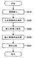
在步骤S410中与第1实施方式同样将由扫描器等输入设备31所读入的有水印文档图像输入到计算机的存储器等(将该图像称为输入图像)。In step S410, the watermarked document image read by the
<文档图像特征量的抽出步骤(步骤S420)><Extraction procedure of document image feature amount (step S420)>
在步骤S420中,将预先所嵌入的与文档图像有关的特征量从在水印检测部32的信息解密步骤(步骤S305)中所解码的数据抽取出。作为本实施方式中的文档图像特征量,使用如图28那样在有水印文档图像中,以嵌入了信号单元的区域的左上坐标为基准点(图28的基准点P)的缩小二值图像。由于嵌入侧的文档图像是二值图像所以仅进行使用了公知技术的缩小处理即可。另外,图像数据也可以在利用MR、MMR等二值图像的压缩方法压缩了数据量的基础上,使用被分配给各符号的信号单元来进行嵌入。In step S420, the previously embedded feature amount related to the document image is extracted from the data decoded in the information decryption step (step S305) of the
<输入图像的二值化处理步骤(步骤S430)><Binarization processing procedure of input image (step S430)>
在步骤S430中,进行输入图像的二值化处理。在本实施方式中,将预先所嵌入的与二值化阈值有关的信息从在水印检测部32的信息解密步骤(步骤S305)中所解码的数据抽取出。从该抽取出的信息来决定二值化阈值,使输入图像二值化。与该二值化阈值有关的信息与第4实施方式中的信号单元数的情况同样,也用利用纠错代码等任意的方法来进行编码,并使用被分配给各符号的信号单元来进行嵌入即可。In step S430, binarization processing of the input image is performed. In the present embodiment, the previously embedded information on the binarization threshold is extracted from the data decoded in the information decryption step (step S305 ) of the
此外,作为与二值化阈值有关的信息,嵌入之际包含在文档图像中的黑像素数等就是一例。在这样的情况下,使对已标准化成与文档图像相同大小的输入图像进行二值化所得到的二值图像的黑像素数与嵌入之际包含在文档图像中的黑像素数相一致这样来设定二值化阈值即可。In addition, as the information related to the binarization threshold, the number of black pixels included in the document image at the time of embedding is an example. In such a case, the number of black pixels in the binary image obtained by binarizing the input image normalized to the same size as the document image is matched with the number of black pixels contained in the document image at the time of embedding. Just set the binarization threshold.
进而,如果将文档图像分成若干个区域,对该区域逐个嵌入与二值化阈值有关的信息,则还能够以输入图像的区域单位来进行二值化处理。通过这样进行处理,对输入图像的某区域施加大幅篡改,该区域的黑像素数就与原来的文档图像的黑像素数大不相同,即便在不处于适当的二值化阈值的范围的情况下,也能够通过参照周边区域的二值化阈值的信息来设定适当的二值化阈值。Furthermore, if the document image is divided into several regions, and the information on the binarization threshold is embedded in each region, the binarization process can also be performed in units of regions of the input image. By doing this, a certain area of the input image is substantially tampered with, and the number of black pixels in this area is very different from that of the original document image, even if it is not in the range of an appropriate binarization threshold. , it is also possible to set an appropriate binarization threshold by referring to the information on the binarization threshold of the surrounding area.
图像的二值化处理也可以利用公知的技术来决定二值化阈值,使输入图像二值化,通过采用上述的方法,即便在水印检测侧也能够创建与嵌入时的文档图像的二值图像大致相同的数据而不依赖于扫描器的机型,。The binarization process of the image can also use a known technique to determine the binarization threshold and binarize the input image. By adopting the above-mentioned method, even on the watermark detection side, it is possible to create a binary image of the document image at the time of embedding. roughly the same data regardless of the scanner model.
<输入图像特征量的抽出步骤(步骤S440)><Extraction Step of Input Image Feature Value (Step S440)>
在步骤S440中,从输入图像和在水印检测部32的信号位置搜索步骤(步骤S320)中所得到的信号单元位置与在信号边界决定步骤(步骤S340)中所得到的信号边界创建与输入图像有关的特征量。具体而言,以信号边界的左上坐标为基准点(图28的基准点Q),将多个信号单元作为一个单位来进行分割,以该单位来求解坐标位置对应的输入图像的缩小图像。在图28中,作为如上述那样所分割的某区域,以左上坐标是(xs,ys)、右下坐标是(xe,ye)的矩形为例来表示。缩小方法利用与嵌入侧相同的方法即可。In step S440, from the input image and the signal unit position obtained in the signal position search step (step S320) of the
此外,在求解缩小图像的情况下,也可以在以信号边界的左上坐标为基准点(图29的基准点Q),将多个信号单元作为一个单位来进行分割,以该单位创建坐标位置对应这样的输入图像的补正图像后对该补正图像进行缩小。In addition, in the case of solving the reduced image, it is also possible to use the upper left coordinate of the signal boundary as a reference point (reference point Q in Figure 29), divide multiple signal units as a unit, and create a coordinate position correspondence with this unit The corrected image of such an input image is reduced in size.
<特征量的比较步骤(步骤S450)><Comparison step of feature amount (step S450)>
在步骤S450中,将在文档图像特征抽出步骤(步骤S420)和输入图像特征创建步骤(步骤S440)中所得到的特征进行比较,如果不一致就判定为对应于该位置的打印文档被篡改。具体而言,通过比较在步骤S440中所得到的每个信号单元单位的输入图像的缩小二值图像(设图28中的基准点为Q的以(xs,ye)-(xs,ye)作为左上/右下顶点的矩形)和与其对应的在文档图像特征抽出步骤(步骤S420)中所抽取出的文档图像的缩小二值图像(设图28中的基准点为P的以(xs,ys)-(xe,ye)为左上/右下顶点的矩形)进行比较来判定篡改。例如在比较对象的2个图像中如果亮度值不同的像素的个数在规定的阈值以上,则判定为与该信号单元相对应的打印文档被篡改即可。In step S450, the features obtained in the document image feature extraction step (step S420) and the input image feature creation step (step S440) are compared, and if inconsistent, it is determined that the printed document corresponding to the position has been tampered with. Specifically, by comparing the reduced binary image of the input image of each signal unit unit obtained in step S440 (set the reference point in Figure 28 as Q, take (xs, ye)-(xs, ye) as upper left/lower right apex) and the corresponding reduced binary image of the document image extracted in the document image feature extraction step (step S420) (assuming that the reference point in Figure 28 is P with (xs, ys )-(xe, ye) are rectangles with upper left/lower right vertices) to compare to determine tampering. For example, if the number of pixels with different luminance values in the two images to be compared is equal to or greater than a predetermined threshold, it may be determined that the printed document corresponding to the signal unit has been tampered with.
此外,虽然在上述的实施方式中,使用了缩小二值图像作为特征量,但也可以取而代之使用坐标信息和在打印文档中所记入的文本数据。在此情况下,能够通过参照与该坐标信息相对应的输入图像的数据,利用公知的OCR技术对该图像信息进行字符识别,并比较该识别结果和文本数据来进行篡改的判定。In addition, although in the above-described embodiment, the reduced binary image is used as the feature amount, coordinate information and text data written in a printed document may be used instead. In this case, by referring to the input image data corresponding to the coordinate information, performing character recognition on the image information by using known OCR technology, and comparing the recognition result with the text data to determine falsification.
(第5实施方式的效果)(Effect of the fifth embodiment)
如以上说明那样,根据本实施方式,就能够通过以利用信号位置搜索模板所决定的信号单元为基准,对预先所嵌入的与文档图像有关的特征量和用扫描器读入嵌入了秘密信息的打印文档的输入图像的特征量进行比较,来检测打印文档的内容是否被篡改。由于通过第1实施方式能够正确地求解信号单元位置,所以如果利用该位置就可容易地进行特征量的比较,并能够判定打印文档的篡改。As described above, according to the present embodiment, by using the signal unit determined by the signal position search template as a reference, it is possible to compare the previously embedded feature quantity related to the document image and the document image embedded secret information with the scanner. The feature quantity of the input image of the printed document is compared to detect whether the content of the printed document has been tampered with. Since the position of the signal unit can be accurately obtained according to the first embodiment, by using this position, comparison of feature values can be easily performed, and falsification of a printed document can be determined.
以上,一边参照附图一边就涉及本发明的水印信息检测方法的优选实施形态进行了说明,但本发明并不限定于这种实施例。显而易见如果是本领域技术人员的话则在权利要求范围所记载的技术思想的范畴内可以想到各种变更例或者修正例,关于它们当然也被认为是属于本发明的技术范围。As above, preferred embodiments of the watermark information detection method according to the present invention have been described with reference to the drawings, but the present invention is not limited to such embodiments. It is obvious that those skilled in the art can conceive various modifications or amendments within the scope of the technical idea described in the claims, and they are naturally considered to belong to the technical scope of the present invention.
如以上说明那样,根据本发明,由于能够对输入图像全部面实施滤波处理,并利用信号位置搜索模板来求解信号单元的位置以使得滤波器输出值的总和成为最大,所以即便在因用纸的歪斜等而使图像伸缩等情况下,也能够正确地检测出信号单元的位置,能够从带有秘密信息的文档准确地检测出秘密信息。As described above, according to the present invention, since the filtering process can be performed on the entire surface of the input image, and the position of the signal unit can be obtained by using the signal position search template so that the sum of the filter output values can be maximized, even when the paper is used Even when the image is stretched or contracted due to skew or the like, the position of the signal unit can be accurately detected, and secret information can be accurately detected from a document with secret information.
产业上的可利用性Industrial availability
本发明可利用于以字符以外的形式对文档图像附加秘密信息的方法和从所打印的带有秘密信息的文档检测出秘密信息的技术。The present invention is applicable to a method of adding secret information to a document image in a form other than characters and a technique of detecting secret information from a printed document with secret information.
Claims (10)
Translated fromChineseApplications Claiming Priority (2)
| Application Number | Priority Date | Filing Date | Title |
|---|---|---|---|
| JP122260/2003 | 2003-04-25 | ||
| JP2003122260 | 2003-04-25 |
Publications (2)
| Publication Number | Publication Date |
|---|---|
| CN1762148A CN1762148A (en) | 2006-04-19 |
| CN100399790Ctrue CN100399790C (en) | 2008-07-02 |
Family
ID=33410070
Family Applications (1)
| Application Number | Title | Priority Date | Filing Date |
|---|---|---|---|
| CNB2004800075750AExpired - Fee RelatedCN100399790C (en) | 2003-04-25 | 2004-04-23 | Watermark Information Detection Method |
Country Status (6)
| Country | Link |
|---|---|
| US (1) | US7440583B2 (en) |
| EP (1) | EP1619874B1 (en) |
| JP (1) | JP4277800B2 (en) |
| KR (1) | KR101016712B1 (en) |
| CN (1) | CN100399790C (en) |
| WO (1) | WO2004098171A1 (en) |
Families Citing this family (33)
| Publication number | Priority date | Publication date | Assignee | Title |
|---|---|---|---|---|
| US7116840B2 (en) | 2002-10-31 | 2006-10-03 | Microsoft Corporation | Decoding and error correction in 2-D arrays |
| US7009594B2 (en)* | 2002-10-31 | 2006-03-07 | Microsoft Corporation | Universal computing device |
| US7133563B2 (en) | 2002-10-31 | 2006-11-07 | Microsoft Corporation | Passive embedded interaction code |
| JP4398474B2 (en)* | 2004-12-28 | 2010-01-13 | 富士通株式会社 | Image processing apparatus for specifying position of processing target in image |
| US7826074B1 (en) | 2005-02-25 | 2010-11-02 | Microsoft Corporation | Fast embedded interaction code printing with custom postscript commands |
| US7421439B2 (en) | 2005-04-22 | 2008-09-02 | Microsoft Corporation | Global metadata embedding and decoding |
| US7400777B2 (en) | 2005-05-25 | 2008-07-15 | Microsoft Corporation | Preprocessing for information pattern analysis |
| JP4552757B2 (en)* | 2005-05-26 | 2010-09-29 | コニカミノルタビジネステクノロジーズ株式会社 | Image processing apparatus, image processing method, and image processing program |
| US7729539B2 (en) | 2005-05-31 | 2010-06-01 | Microsoft Corporation | Fast error-correcting of embedded interaction codes |
| US7817816B2 (en) | 2005-08-17 | 2010-10-19 | Microsoft Corporation | Embedded interaction code enabled surface type identification |
| JP4555212B2 (en)* | 2005-11-10 | 2010-09-29 | 株式会社沖データ | Watermark information embedding device, watermark information embedding method, and computer program |
| JP4979956B2 (en) | 2006-02-07 | 2012-07-18 | 株式会社沖データ | Digital watermark embedding apparatus and digital watermark embedding method |
| JP2008135987A (en)* | 2006-11-28 | 2008-06-12 | Fujitsu Ltd | Information embedding apparatus, information embedded printed matter, information embedding method, and information embedding program |
| JP5014832B2 (en)* | 2007-02-27 | 2012-08-29 | 株式会社沖データ | Image processing apparatus, image processing method, and computer program |
| JP4842872B2 (en)* | 2007-03-29 | 2011-12-21 | 株式会社沖データ | Form processing device |
| US20090010483A1 (en)* | 2007-07-02 | 2009-01-08 | The Hong Kong University Of Science And Technology | Block-based lossless data hiding in the delta domain |
| US7974437B2 (en)* | 2007-11-19 | 2011-07-05 | Seiko Epson Corporation | Identifying steganographic data in an image |
| US8081823B2 (en)* | 2007-11-20 | 2011-12-20 | Seiko Epson Corporation | Segmenting a string using similarity values |
| US8031905B2 (en)* | 2007-11-21 | 2011-10-04 | Seiko Epson Corporation | Extracting data from images |
| US8243981B2 (en)* | 2007-11-26 | 2012-08-14 | Seiko Epson Corporation | Identifying embedded data in an image |
| US8009862B2 (en)* | 2007-11-27 | 2011-08-30 | Seiko Epson Corporation | Embedding data in images |
| JP4587058B2 (en)* | 2008-09-10 | 2010-11-24 | 富士ゼロックス株式会社 | Image processing apparatus, image processing system, and program |
| US8275168B2 (en)* | 2009-08-28 | 2012-09-25 | Seiko Epson Corporation | Orientation free watermarking message decoding from document scans |
| JP5128563B2 (en)* | 2009-09-17 | 2013-01-23 | 株式会社日立製作所 | Document verification system, document verification method, document verification program, and recording medium |
| KR20150022276A (en)* | 2013-08-22 | 2015-03-04 | 삼성전자주식회사 | Apparatas and method for extravting a encrypted message of image file in an electronic device |
| WO2016028934A1 (en)* | 2014-08-20 | 2016-02-25 | Verance Corporation | Content management based on dither-like watermark embedding |
| US10521931B2 (en)* | 2014-12-19 | 2019-12-31 | Hewlett-Packard Development Company, L.P. | Determine image capture position information based on a quasi-periodic pattern |
| CN106033543A (en)* | 2015-03-11 | 2016-10-19 | 株式会社理光 | Document modification detecting method, original document manuscript providing device, duplicated document detecting device, and document modification detection system |
| US10387531B1 (en)* | 2015-08-18 | 2019-08-20 | Google Llc | Processing structured documents using convolutional neural networks |
| JP6707947B2 (en)* | 2016-03-29 | 2020-06-10 | 株式会社リコー | Image processing device, image processing method, and program |
| JP6958241B2 (en)* | 2017-10-31 | 2021-11-02 | 富士通株式会社 | Change detection program, change detection method and change detection device |
| CN111443329A (en)* | 2020-03-25 | 2020-07-24 | 北京东方振动和噪声技术研究所 | Sound source positioning method and device, computer storage medium and electronic equipment |
| CN113313214B (en)* | 2021-07-30 | 2021-11-16 | 北京惠朗世纪科技有限公司 | Identification method and system of watermarked character based on multiple convolution kernels posterior |
Citations (4)
| Publication number | Priority date | Publication date | Assignee | Title |
|---|---|---|---|---|
| JP2001188549A (en)* | 1999-12-29 | 2001-07-10 | Sony Corp | Information process, information processing method and program storage medium |
| JP2002354227A (en)* | 2001-05-29 | 2002-12-06 | Sony Corp | Method and device for electronic watermark embedding processing and program |
| JP2003101747A (en)* | 2001-09-19 | 2003-04-04 | Glory Ltd | Digital watermark system, digital watermark embedded device, digital watermark detector, method and program for embedding digital watermark |
| JP2003101762A (en)* | 2001-07-18 | 2003-04-04 | Oki Electric Ind Co Ltd | Watermark information embedding device and watermark information detection device |
Family Cites Families (15)
| Publication number | Priority date | Publication date | Assignee | Title |
|---|---|---|---|---|
| US5315098A (en)* | 1990-12-27 | 1994-05-24 | Xerox Corporation | Methods and means for embedding machine readable digital data in halftone images |
| US5721788A (en)* | 1992-07-31 | 1998-02-24 | Corbis Corporation | Method and system for digital image signatures |
| US5576532A (en)* | 1995-01-03 | 1996-11-19 | Xerox Corporation | Interleaved and interlaced sync codes and address codes for self-clocking glyph codes |
| JP3881733B2 (en) | 1995-09-30 | 2007-02-14 | インテック・ウェブ・アンド・ゲノム・インフォマティクス株式会社 | Confidential information recording method |
| JP3617230B2 (en) | 1997-01-14 | 2005-02-02 | 富士ゼロックス株式会社 | Document processing device |
| US5864742A (en)* | 1997-04-11 | 1999-01-26 | Eastman Kodak Company | Copy restrictive system using microdots to restrict copying of color-reversal documents |
| US5949055A (en)* | 1997-10-23 | 1999-09-07 | Xerox Corporation | Automatic geometric image transformations using embedded signals |
| JP3373811B2 (en) | 1999-08-06 | 2003-02-04 | インターナショナル・ビジネス・マシーンズ・コーポレーション | Method and apparatus for embedding and detecting watermark information in black and white binary document image |
| JP2001053954A (en) | 1999-08-17 | 2001-02-23 | Ntt Data Corp | Device and method for embedding information and reading information, digital watermark system and recording medium |
| JP4099951B2 (en)* | 2000-03-30 | 2008-06-11 | コニカミノルタビジネステクノロジーズ株式会社 | Image processing apparatus, image forming apparatus, information embedding method, and program for embedding additional information in image data |
| US6763121B1 (en)* | 2000-06-14 | 2004-07-13 | Hewlett-Packard Development Company, L.P. | Halftone watermarking method and system |
| US6839450B2 (en)* | 2001-04-26 | 2005-01-04 | Hewlett-Packard Development Company, L.P. | Detecting halftone modulations embedded in an image |
| US7039215B2 (en) | 2001-07-18 | 2006-05-02 | Oki Electric Industry Co., Ltd. | Watermark information embedment device and watermark information detection device |
| US7085399B2 (en)* | 2002-06-18 | 2006-08-01 | Oki Electric Industry Co., Ltd. | Watermark information embedding device and watermark information detection device |
| JP2005150815A (en)* | 2003-11-11 | 2005-06-09 | Oki Electric Ind Co Ltd | Watermark information embedding apparatus and method, watermark information detecting apparatus and method, and printed matter |
- 2004
- 2004-04-23EPEP04729191.9Apatent/EP1619874B1/ennot_activeExpired - Lifetime
- 2004-04-23JPJP2004570200Apatent/JP4277800B2/ennot_activeExpired - Fee Related
- 2004-04-23CNCNB2004800075750Apatent/CN100399790C/ennot_activeExpired - Fee Related
- 2004-04-23KRKR1020057019823Apatent/KR101016712B1/ennot_activeExpired - Fee Related
- 2004-04-23USUS10/553,632patent/US7440583B2/ennot_activeExpired - Lifetime
- 2004-04-23WOPCT/JP2004/005863patent/WO2004098171A1/enactiveApplication Filing
Patent Citations (4)
| Publication number | Priority date | Publication date | Assignee | Title |
|---|---|---|---|---|
| JP2001188549A (en)* | 1999-12-29 | 2001-07-10 | Sony Corp | Information process, information processing method and program storage medium |
| JP2002354227A (en)* | 2001-05-29 | 2002-12-06 | Sony Corp | Method and device for electronic watermark embedding processing and program |
| JP2003101762A (en)* | 2001-07-18 | 2003-04-04 | Oki Electric Ind Co Ltd | Watermark information embedding device and watermark information detection device |
| JP2003101747A (en)* | 2001-09-19 | 2003-04-04 | Glory Ltd | Digital watermark system, digital watermark embedded device, digital watermark detector, method and program for embedding digital watermark |
Also Published As
| Publication number | Publication date |
|---|---|
| KR101016712B1 (en) | 2011-02-25 |
| EP1619874A1 (en) | 2006-01-25 |
| WO2004098171A1 (en) | 2004-11-11 |
| EP1619874B1 (en) | 2016-02-03 |
| JP4277800B2 (en) | 2009-06-10 |
| US20070005977A1 (en) | 2007-01-04 |
| JPWO2004098171A1 (en) | 2006-07-13 |
| CN1762148A (en) | 2006-04-19 |
| KR20060003027A (en) | 2006-01-09 |
| US7440583B2 (en) | 2008-10-21 |
| EP1619874A4 (en) | 2007-09-12 |
Similar Documents
| Publication | Publication Date | Title |
|---|---|---|
| CN100399790C (en) | Watermark Information Detection Method | |
| JP3628312B2 (en) | Watermark information embedding device and watermark information detection device | |
| US7085399B2 (en) | Watermark information embedding device and watermark information detection device | |
| US7245740B2 (en) | Electronic watermark embedding device, electronic watermark detection device, electronic watermark embedding method, and electronic watermark detection method | |
| JP3964684B2 (en) | Digital watermark embedding device, digital watermark detection device, digital watermark embedding method, and digital watermark detection method | |
| US7039215B2 (en) | Watermark information embedment device and watermark information detection device | |
| US6086706A (en) | Document copying deterrent method | |
| CN101119429A (en) | A method and device for digital watermark embedding and extraction | |
| CN101366266A (en) | Method and device for embedding and detecting digital watermark in text document | |
| CN101257545A (en) | Image processing device, image processing method, and computer program | |
| KR101086802B1 (en) | Watermark information embedding apparatus and method, watermark information detecting apparatus and method, watermarked document | |
| Tan et al. | Print-Scan Resilient Text Image Watermarking Based on Stroke Direction Modulation for Chinese Document Authentication. | |
| US20100142756A1 (en) | Document security method | |
| Chen et al. | Recent developments in document image watermarking and data hiding | |
| AU2006252223B2 (en) | Tamper Detection of Documents using Encoded Dots | |
| EP1684496A1 (en) | Watermark information embedding device, watermark information detection device, watermark information embedding method, watermark information detection method, and printed matter | |
| JP3980983B2 (en) | Watermark information embedding method, watermark information detecting method, watermark information embedding device, and watermark information detecting device | |
| JP3999778B2 (en) | Image processing method and image processing apparatus | |
| JP4192887B2 (en) | Tamper detection device, watermarked image output device, watermarked image input device, watermarked image output method, and watermarked image input method | |
| JP2007088693A (en) | Image processing system, tampering verification apparatus, tampering verification method, and computer program | |
| Cheng et al. | Steganalysis of binary text images | |
| JP4192906B2 (en) | Watermark information detection apparatus and watermark information detection method | |
| JP2006157831A (en) | Tampering detector, watermarked image outputting device, watermarked image inputting device, watermarked image output method, and watermarked image input method | |
| LL00SLLL | United States Patent po [11] Patent Number: 6,086,706 | |
| Albakaa | Self-validating Binary Document Images |
Legal Events
| Date | Code | Title | Description |
|---|---|---|---|
| C06 | Publication | ||
| PB01 | Publication | ||
| C10 | Entry into substantive examination | ||
| SE01 | Entry into force of request for substantive examination | ||
| C14 | Grant of patent or utility model | ||
| GR01 | Patent grant | ||
| ASS | Succession or assignment of patent right | Owner name:JAPAN ROH INFORMATION CO., LTD. Free format text:FORMER OWNER: OKI ELECTRICAL INDUSTRY CO., LTD. Effective date:20100519 | |
| C41 | Transfer of patent application or patent right or utility model | ||
| TR01 | Transfer of patent right | Effective date of registration:20100519 Address after:Tokyo, Japan Patentee after:Oki Data K. K. Address before:Tokyo, Japan Patentee before:Oki Electric Industry Co., Ltd. | |
| CF01 | Termination of patent right due to non-payment of annual fee | ||
| CF01 | Termination of patent right due to non-payment of annual fee | Granted publication date:20080702 Termination date:20160423 |