CN100399253C - Input device, microcomputer and information processing method - Google Patents
Input device, microcomputer and information processing methodDownload PDFInfo
- Publication number
- CN100399253C CN100399253CCNB2005101076051ACN200510107605ACN100399253CCN 100399253 CCN100399253 CCN 100399253CCN B2005101076051 ACNB2005101076051 ACN B2005101076051ACN 200510107605 ACN200510107605 ACN 200510107605ACN 100399253 CCN100399253 CCN 100399253C
- Authority
- CN
- China
- Prior art keywords
- contact
- key
- input device
- input
- keyboard
- Prior art date
- Legal status (The legal status is an assumption and is not a legal conclusion. Google has not performed a legal analysis and makes no representation as to the accuracy of the status listed.)
- Expired - Fee Related
Links
Images


Classifications
- G—PHYSICS
- G06—COMPUTING OR CALCULATING; COUNTING
- G06F—ELECTRIC DIGITAL DATA PROCESSING
- G06F3/00—Input arrangements for transferring data to be processed into a form capable of being handled by the computer; Output arrangements for transferring data from processing unit to output unit, e.g. interface arrangements
- G06F3/01—Input arrangements or combined input and output arrangements for interaction between user and computer
- G06F3/03—Arrangements for converting the position or the displacement of a member into a coded form
- G06F3/041—Digitisers, e.g. for touch screens or touch pads, characterised by the transducing means
- G06F3/0416—Control or interface arrangements specially adapted for digitisers
- G06F3/0418—Control or interface arrangements specially adapted for digitisers for error correction or compensation, e.g. based on parallax, calibration or alignment
- G—PHYSICS
- G06—COMPUTING OR CALCULATING; COUNTING
- G06F—ELECTRIC DIGITAL DATA PROCESSING
- G06F3/00—Input arrangements for transferring data to be processed into a form capable of being handled by the computer; Output arrangements for transferring data from processing unit to output unit, e.g. interface arrangements
- G06F3/01—Input arrangements or combined input and output arrangements for interaction between user and computer
- G06F3/048—Interaction techniques based on graphical user interfaces [GUI]
- G06F3/0487—Interaction techniques based on graphical user interfaces [GUI] using specific features provided by the input device, e.g. functions controlled by the rotation of a mouse with dual sensing arrangements, or of the nature of the input device, e.g. tap gestures based on pressure sensed by a digitiser
- G06F3/0488—Interaction techniques based on graphical user interfaces [GUI] using specific features provided by the input device, e.g. functions controlled by the rotation of a mouse with dual sensing arrangements, or of the nature of the input device, e.g. tap gestures based on pressure sensed by a digitiser using a touch-screen or digitiser, e.g. input of commands through traced gestures
- G06F3/04886—Interaction techniques based on graphical user interfaces [GUI] using specific features provided by the input device, e.g. functions controlled by the rotation of a mouse with dual sensing arrangements, or of the nature of the input device, e.g. tap gestures based on pressure sensed by a digitiser using a touch-screen or digitiser, e.g. input of commands through traced gestures by partitioning the display area of the touch-screen or the surface of the digitising tablet into independently controllable areas, e.g. virtual keyboards or menus
Landscapes
- Engineering & Computer Science (AREA)
- General Engineering & Computer Science (AREA)
- Theoretical Computer Science (AREA)
- Human Computer Interaction (AREA)
- Physics & Mathematics (AREA)
- General Physics & Mathematics (AREA)
- Position Input By Displaying (AREA)
Abstract
Description
Translated fromChinese相关申请的交叉引用Cross References to Related Applications
本申请要求以2004年9月29提出的在先的日本专利申请2004-285453作为优先权基础,在这里全文引用该申请的内容作为参考。This application claims priority based on prior Japanese Patent Application No. 2004-285453 filed on September 29, 2004, the contents of which are incorporated herein by reference in its entirety.
技术领域technical field
本发明涉及将信息馈入到计算机等等中的输入设备。This invention relates to input devices for feeding information into computers and the like.
背景技术Background technique
通常,计算机终端的接口包括键盘和鼠标作为输入设备,阴极射线管(CRT)或液晶显示器(LCD)作为显示单元。Generally, the interface of a computer terminal includes a keyboard and a mouse as input devices, and a cathode ray tube (CRT) or a liquid crystal display (LCD) as a display unit.
此外,其中显示单元和输入设备彼此层叠的所谓的触板也广泛地用作计算机终端、小型便携式平板型计算器等等的接口。Furthermore, a so-called touch panel in which a display unit and an input device are stacked on each other is also widely used as an interface of a computer terminal, a small portable tablet type calculator, and the like.
日本专利公开出版物No.2003-196,007说明了用来向具有小型正面的移动电话或个人数字助理(PDA)输入字符的触板。Japanese Patent Laid-Open Publication No. 2003-196,007 describes a touch panel for inputting characters into a mobile phone or a personal digital assistant (PDA) having a small front.
然而,利用相关技术,诸如指尖或输入笔之类的对象在触板上的接触位置常常偏离正确的位置,因为手掌大小或视野在不同的个体之间各不相同。However, with the related art, the contact position of an object such as a fingertip or a stylus on the touch pad often deviates from the correct position because palm size or field of view varies among different individuals.
本发明的目的在于克服相关技术的上述问题,并提供可以适当地检测对象的接触位置的输入设备。An object of the present invention is to overcome the above-mentioned problems of the related art, and to provide an input device that can appropriately detect a contact position of an object.
发明内容Contents of the invention
根据本实施例的第一个方面,提供了一种输入设备,包括:显示单元,指示代表输入位置的图像;接触位置检测单元,检测与显示单元的接触检测表面进行接触的对象的接触位置;存储器,存储代表了被接触位置检测单元检测到的接触位置与代表显示单元指示的输入位置的图像的中心之间的差别的数据;运算单元,根据存储器所存储的数据来计算用于校正代表输入位置的图像的位置的量;校正单元,根据运算单元计算的量,将代表输入位置的由显示单元指示的图像的位置校正为由接触位置检测单元检测出的接触位置。According to a first aspect of the present embodiment, there is provided an input device including: a display unit indicating an image representing an input position; a contact position detection unit detecting a contact position of an object in contact with a contact detection surface of the display unit; a memory storing data representing the difference between the contact position detected by the contact position detection unit and the center of the image representing the input position indicated by the display unit; The quantity of the position of the image of the position; the correction unit corrects the position of the image indicated by the display unit representing the input position to the contact position detected by the contact position detection unit based on the quantity calculated by the operation unit.
根据第二个方面,提供了一种微电脑,包括:指示代表输入位置的图像的显示单元;检测与显示单元的接触检测表面进行接触的对象的位置的接触位置检测单元;存储代表被检测到的位置和代表输入位置的图像的中心之间的差别的数据的存储器;根据存储器存储的数据来计算校正代表输入位置的图像的量的运算单元;检测与显示单元的显示层上所提供的接触检测层进行接触的对象的位置的接触位置检测单元;以及根据对象的检测到的接触状态和输入到输入设备的信息进行处理的处理单元。According to a second aspect, there is provided a microcomputer comprising: a display unit indicating an image representing an input position; a contact position detection unit detecting a position of an object in contact with a contact detection surface of the display unit; A memory for data of the difference between the position and the center of the image representing the input position; an arithmetic unit for calculating the amount of correction of the image representing the input position based on the data stored in the memory; detection of contact detection provided on the display layer with the display unit a contact position detection unit for layering the position of an object making contact; and a processing unit for performing processing based on the detected contact state of the object and information input to the input device.
根据第三个方面,提供了一种微电脑,包括:存储指示代表输入位置的显示单元的接触检测表面上的对象的接触位置与代表输入位置的图像的中心之间的差别的存储器;根据存储器中存储的数据来计算校正代表输入位置的图像的校正量的运算单元;根据对象的检测到的接触状态进行处理的处理单元。According to a third aspect, there is provided a microcomputer comprising: a memory for storing a difference between a contact position of an object on a contact detection surface indicating a display unit representing an input position and a center of an image representing the input position; An arithmetic unit that calculates a correction amount for correcting an image representing an input position from the stored data; a processing unit that performs processing according to the detected contact state of the object.
根据第四个方面,提供了一种信息处理方法,包括:指示代表显示单元上的输入位置的图像;检测与显示单元的接触检测表面接触的对象的接触位置;存储代表被检测到的接触位置与代表由显示单元所指示的输入位置的图像的中心之间的差别的数据;根据存储的数据来计算用于校正代表输入位置的图像的位置的量;根据所计算的量,把代表输入位置的图像的位置校正到所检测的接触位置;以及,在显示单元上指示校正的图像。According to a fourth aspect, there is provided an information processing method including: indicating an image representing an input position on a display unit; detecting a contact position of an object in contact with a contact detection surface of the display unit; storing the representative detected contact position data representing the difference between the center of the image representing the input position indicated by the display unit; calculating an amount for correcting the position of the image representing the input position based on the stored data; based on the calculated amount, representing the input position The position of the image of is corrected to the detected contact position; and, the corrected image is indicated on the display unit.
附图说明Description of drawings
图1是根据本发明的第一实施例的便携式微电脑的透视图;1 is a perspective view of a portable microcomputer according to a first embodiment of the present invention;
图2是该便携式微电脑的输入部分的透视图;Fig. 2 is the perspective view of the input part of this portable microcomputer;
图3A是该便携式微电脑的触板的透视图;Fig. 3 A is the perspective view of the touch panel of this portable microcomputer;
图3B是图3A的触板的俯视图;3B is a top view of the touch panel of FIG. 3A;
图3C是图3A的触板的剖面图;3C is a cross-sectional view of the touch panel of FIG. 3A;
图4是显示了该便携式微电脑的的输入设备的配置的方框图;Fig. 4 is a block diagram showing the configuration of the input device of the portable microcomputer;
图5是该便携式微电脑的方框图;Fig. 5 is the block diagram of this portable microcomputer;
图6是显示了与触板进行接触的对象的接触区域的大小的变化的图形;6 is a graph showing changes in the size of a contact area of an object making contact with a touch panel;
图7是显示了与触板进行接触以便输入信息的对象的接触区域的大小的变化的图形;7 is a graph showing changes in the size of a contact area of an object that makes contact with a touch panel to input information;
图8A是将压力转换为电信号的触板的透视图;Figure 8A is a perspective view of a touch pad that converts pressure into an electrical signal;
图8B是图8A所示的触板的俯视图;FIG. 8B is a top view of the touch panel shown in FIG. 8A;
图8C是触板的剖面图;8C is a cross-sectional view of the touch panel;
图9是显示了触板的接触检测器的配置的示意图;9 is a schematic diagram showing the configuration of a contact detector of a touch panel;
图10是显示了当用适度的压力推压时检测到的接触检测器的示意图;Fig. 10 is a schematic diagram showing a contact detector detected when pushed with a moderate pressure;
图11是显示了当用中等压力推压时检测到的接触检测器的示意图;Fig. 11 is a schematic diagram showing a contact detector detected when pushed with moderate pressure;
图12是显示了当用中等压力推压时检测到的接触检测器的示意图;Fig. 12 is a schematic diagram showing a contact detector detected when pushed with moderate pressure;
图13是显示了当用较大压力推压时检测到的接触检测器的示意图;Fig. 13 is a schematic diagram showing a contact detector detected when pushed with a large pressure;
图14是显示了当用最大的压力推压时检测到的接触检测器的示意图;FIG. 14 is a schematic diagram showing a contact detector detected when pushed with maximum pressure;
图15是该便携式微电脑的下部外壳的透视图;Fig. 15 is the perspective view of the lower casing of this portable microcomputer;
图16是该便携式微电脑的输入设备的俯视图,显示了用户的手掌放置在输入设备上以便输入信息;16 is a top view of the input device of the portable microcomputer, showing that the user's palm is placed on the input device to input information;
图17是输入设备的俯视图,显示了用户的手指在敲击键;Fig. 17 is a top view of an input device showing a user's fingers tapping a key;
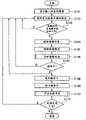
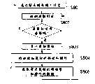
图18是输入设备进行的信息处理步骤的流程图;Fig. 18 is a flowchart of the information processing steps performed by the input device;
图19是显示了图18所示的步骤S106的细节的流程图;FIG. 19 is a flowchart showing details of step S106 shown in FIG. 18;
图20是输入设备进行的进一步的信息处理步骤的流程图;Figure 20 is a flowchart of further information processing steps performed by the input device;
图21是显示了图20所示的步骤S210的细节的流程图;FIG. 21 is a flowchart showing details of step S210 shown in FIG. 20;
图22显示了输入设备的键顶的被敲击部分;Figure 22 shows a struck portion of a keytop of an input device;
图23显示了输入设备的键顶的被敲击部分的另一个示例;Figure 23 shows another example of a struck portion of a keytop of an input device;
图24是显示了自动调整过程的流程图;Figure 24 is a flowchart showing the automatic adjustment process;
图25是显示了进一步的自动调整过程的流程图;Figure 25 is a flowchart showing a further automatic adjustment process;
图26是显示了打字练习过程的流程图;Figure 26 is a flowchart showing the typing practice process;
图27是显示了打字练习过程中键命中率的图形;Fig. 27 is a graph showing the key hit rate during typing practice;
图28是显示了重新键入过程中的自动调整过程的流程图;Figure 28 is a flowchart showing the auto-adjustment process during rekeying;
图29是显示了鼠标使用模式的流程图;Fig. 29 is a flowchart showing the mouse usage mode;
图30A显示了其中用户将要使用鼠标的状态;FIG. 30A shows a state in which the user is about to use the mouse;
图30B显示了鼠标;Figure 30B shows a mouse;
图31显示了视野校准过程;Figure 31 shows the field of view calibration process;
图32显示了另一个视野校准过程;Figure 32 shows another field of view calibration process;
图33显示了再一个视野校准过程;Figure 33 shows yet another field of view calibration process;
图34是显示了视野校准过程的流程图;Figure 34 is a flowchart showing the field of view calibration process;
图35显示了偏离中心的键命中量;Figure 35 shows the amount of off-center key hits;
图36显示了偏离中心的键命中状态;Figure 36 shows the off-center key hit state;
图37显示了接触区域的大小;Figure 37 shows the size of the contact area;
图38是显示了接触区域在x方向的大小的变化的图形;Figure 38 is a graph showing the change in the size of the contact area in the x direction;
图39是显示了接触区域在y方向的大小的变化的图形;Figure 39 is a graph showing the change in the size of the contact area in the y direction;
图40是显示了第一个视野校准过程的流程图;Figure 40 is a flowchart showing the first field of view calibration process;
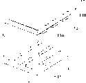
图41是另一个实施例的输入设备的透视图;Figure 41 is a perspective view of an input device of another embodiment;
图42是再一个实施例中的输入设备的方框图;Figure 42 is a block diagram of an input device in yet another embodiment;
图43是又一个实施例中的输入设备的方框图;Figure 43 is a block diagram of an input device in yet another embodiment;
图44是另一个实施例的方框图;以及Figure 44 is a block diagram of another embodiment; and
图45是最后的实施例的触板的透视图。Figure 45 is a perspective view of the touch panel of the last embodiment.
具体实施方式Detailed ways
下面将参考附图描述本发明的各个实施例。值得注意的是,对附图中的相同的或类似的部件和元件应用了相同的或类似的参考编号,将不再对相同的或类似的部件和元件进行描述。Various embodiments of the present invention will be described below with reference to the accompanying drawings. It is to be noted that the same or similar reference numerals are applied to the same or similar parts and elements in the drawings, and the same or similar parts and elements will not be described again.
第一实施例:First embodiment:
在本实施例中,本发明涉及输入设备,这是计算机的终端设备的一种输入输出设备。In this embodiment, the present invention relates to an input device, which is an input and output device of a terminal device of a computer.
请参看图1,便携式微电脑1(简称为“微电脑1”)包括计算机主单元30、下外壳2A和上外壳2B。计算机主单元30包括诸如中央处理单元之类的运算和逻辑单元。下外壳2A封装了输入单元3作为计算机主单元30的用户界面。上外壳2B封装了具有液晶显示面板29(简称为“显示面板29”)的显示单元4。Referring to FIG. 1, a portable microcomputer 1 (abbreviated as "
计算机主单元30使用中央处理单元以便处理通过输入单元3接收到的信息。在上外壳2B中的显示单元4上指出了被处理的信息。The computer
下外壳2A中的输入单元3包括显示单元5,以及用于检测对象(如用户的手指或输入笔)与显示单元5的显示面板的接触状态的检测单元。显示单元5指示了向用户通知输入位置的图像,例如,用来供用户输入信息的虚拟键盘5a上的键、虚拟鼠标5b、各种输入键、左右按钮、滚动轮,等等。The
输入单元3进一步包括具有发光区域的背光灯6,以及层叠在显示单元5上的触板10,如图2所示。具体来说,显示单元5层叠在背光灯6的发光区域上。The
背光灯6可以通过荧光灯管和广泛地用作微电脑的显示器的光波导管的组合来构成,或者也可以通过在平面上提供的多个白光发光二极管(LED)来实现。这样的LED最近已投入实际应用中。The
背光灯6和显示单元5两者的结构可以类似于常规微电脑的显示单元的结构或台式计算机的外部LCD显示器的结构。如果显示单元5是发光型,则可以省略背光灯6。Both the structure of the
显示单元5包括在x和y方向提供的并呈现矩阵形状的多个像素5c,并通过显示驱动器22来驱动(如图4所示),并指示代表诸如键盘等等之类的输入位置的图像。The
触板10位于输入单元3的顶层,被暴露在下外壳2A上,并被驱动以便接收信息。触板10检测与检测层10a进行接触的对象(用户的手指或输入笔)。The
在第一实施例中,触板10是电阻薄膜型。目前有模拟和数字电阻薄膜型触板。使用了4到8线型模拟触板。基本上,利用并联的电极,检测对象接触到电极的点的电势,根据检测到的电势导出接触点的坐标。并联电极独立地层叠在X和Y方向,这样便可以检测到接触点的X和Y坐标。然而,利用模拟类型,很难同时检测多个接触点。此外,模拟触板不适合用于检测接触区域的尺寸。因此,在第一实施例中利用了数字触板,以便检测接触点和接触区域的尺寸。在任何情况下,接触检测层10a是透明的,以便显示单元5从正面可见。In the first embodiment, the
请参看图3A和3B,触板10包括基底11和基底13。基底11包括多个(n)带状X电极12,这些电极在X方向上按规律的间隔排列。另一方面,基底13包括多个(m)带状Y电极14,这些电极在Y方向上按规律的间隔排列。基底11和13与它们的电极层叠,并彼此面对面。简而言之,X电极12和Y电极14彼此垂直。因此,在X电极12和Y电极14的交叉点处有(nXm)个接触检测器10b呈矩阵的形状排列。Referring to FIGS. 3A and 3B , the
在基底11上的X电极之间提供了许多凸状弯曲的点垫片15。点垫片15由绝缘材料制成,并以规律的间隔排列。点垫片15的高度大于X和Y电极12和14的总厚度。点垫片15的顶部与Y电极14之间的基底13的外露区域13A接触。如图3C所示,基底11和13将点垫片15夹入中间,并且不与X和Y电极12和14接触。简而言之,X和Y电极12和14通过点垫片15而彼此不接触。当基底13被推入前述的状态时,X和Y电极12和14彼此进行接触。A number of convexly
基底13的与安装了Y电极的表面相对的表面13B暴露在下外壳2A上,并用于输入信息。换句话说,当表面13B被用户的手指或输入笔按下时,Y电极14与X电极12接触。A
如果用户的手指或输入笔施加的压力等于或小于预定压力,则基底13不充分弯曲,这会防止Y电极14和X电极12彼此进行接触。只有在施加的压力大于预先确定的值的情况下,基底13被充分弯曲,以便Y电极14和X电极12彼此接触,并变得可以导电。If the pressure applied by the user's finger or the stylus is equal to or less than the predetermined pressure, the
Y和X电极14和12的接触点通过输入单元3的接触检测单元21(如图4所示)来进行检测。The contact points of the Y and
对于微电脑1,下外壳2A不仅封装了输入单元3(如图1所示)而且还封装了输入设备20(如图4所示),其包括用于检测触板10的X和Y电极12和14的接触点并识别与触板10接触的对象的形状的接触检测单元21。For the
请参看图2和图4,输入设备20包括输入单元3、接触检测单元21、设备控制IC 23、存储器24、扬声器驱动器25以及扬声器26。设备控制IC 23将检测到的接触位置数据转换为数字信号,并进行涉及各种类型的处理(稍后描述)的I/O控制,并进行往返于计算机主单元30的通信。扬声器驱动器25和扬声器26用于发出各种口头通知或通知的嘟嘟声。2 and 4, the
接触检测单元21一个接一个地向X电极12施加电压,测量Y电极14上的电压,并检测产生了等于向X电极施加的电压的电压的特定Y电极14。The
触板10包括由电源和开关部件构成的电压施加单元11a。响应来自接触检测单元21的电极选择信号,开关部件按顺序选择X电极12,电压施加单元11a从电源向所选择的X电极12施加参考电压。The
此外,触板10还包括电压表11b,该电压表有选择地测量由来自接触检测单元21的电极选择信号所指定的Y电极14的电压,并将测量到的结果返回到接触检测单元21。In addition, the
当触板10被用户的手指或输入笔按下时,被按下的位置处的X和Y电极12和14彼此接触,并变得可以导电。在触板10被按下的位置,通过Y电极14测量向X电极12施加的参考电压。因此,当参考电压被检测为Y电极14的输出电压时,接触检测单元21可以识别Y电极14,和被施加了参考电压的X电极12。此外,接触检测单元21可以根据X电极12和Y电极14的组合识别被用户的手指或输入笔按下的接触检测器10b。When the
接触检测单元21反复并快速地检测X和Y电极12和14的接触状态,并准确地检测多个被同时按下的X和Y电极12和14,具体取决于X和Y电极12和14的间隔。The
例如,如果触板20被用户的手指有力地按下,则接触区域被扩大。扩大的接触区域意味着有多个接触检测器10b被按下。在这样的情况下,接触检测单元21反复并快速地向X电极12施加参考电压,并反复而快速地测量Y电极14处的电压。因此,可以检测一次按下的接触检测器10b。接触检测单元21可以根据检测到的接触检测器10b检测接触区域的大小。For example, if the
响应来自设备控制IC 23的命令,显示驱动器22指示被用作输入设备(即,用户的接口)的按钮、图标、键盘、10键小键盘、鼠标等等的一个或多个图像。背光灯6发出的光从其背面穿过LCD,以便从正面可以观察显示单元5上的图像。In response to a command from the device control IC 23, the
设备控制IC 23根据虚拟键盘(在显示单元5上指示)上的键位置和接触位置以及接触检测单元21所检测到的接触区域来识别接触点处的键的图像。有关识别的键的信息被通知给计算机主单元30。The device control IC 23 recognizes the image of the key at the contact point from the key position and contact position on the virtual keyboard (indicated on the display unit 5) and the contact area detected by the
计算机主单元30控制用于从设备控制IC 23接收到的信息的操作。The computer
请参看图5,在主板30a(用作为计算机主单元30)中,北桥31和南桥32使用专用的高速总线B1连接在一起。北桥31通过系统总线B2连接到中央处理单元33(简称为“CPU 33”),并通过存储器总线B3连接到主存储器34,以及通过加速图形端口总线B4(简称为“AGP总线B4”)连接到图形电路35。Please refer to FIG. 5 , in the
图形电路35将数字图像信号输出到上外壳2B中的显示面板4的显示驱动器28。响应接收到的信号,显示驱动器28激励显示面板29。显示面板29在其显示面板(LCD)上显示图像。
此外,南桥32通过PCI总线B5连接到外围组件互连设备37(称为“PCI设备37”),并通过USB总线B6连接到通用串行总线设备38(称为“USB设备38”)。南桥32可以通过PCI设备37将各种单元连接到PCI总线35,并通过USB总线B6将各种单元连接到USB设备38。Further, the
更进一步,南桥32通过集成驱动器电子接口39(称为“IDE接口39”)并通过AT连接总线B7(称为“ATA总线37”)连接到硬盘驱动器41(称为“HDD 41”)。此外,南桥32通过低插脚统计总线B8(称为“LCP总线B8”)连接到可移动介质设备(磁盘设备)44、串行/并行端口45和键盘/鼠标端口46。键盘/鼠标端口46给南桥32提供从输入设备20接收到的信号,并指示键盘或鼠标的操作。因此,信号通过北桥31被传输到CPU 33。CPU 33响应接收到的信号来进行处理。Still further, the
南桥32还通过专用总线连接到音频信号输出电路47。音频信号输出电路47将音频信号提供到位于计算机主单元30内的扬声器48。因此,扬声器48输出各种声音。The
CPU 33执行存储在HDD 41和主存储器34中的各种程序,以便在显示单元4(位于上外壳2B中)的显示面板29上显示出图像,通过扬声器48(位于下外壳2A中)输出声音。此后,CPU 33根据来自输入设备20的指示键盘或鼠标的操作的信号执行各操作。具体来说,CPU 33响应于涉及键盘或鼠标的操作的信号控制图形电路35。因此,图形电路35向显示单元5输出数字图像信号,而显示单元5又显示对应于键盘或鼠标的操作的图像。然后,CPU 33控制音频信号输出电路47,该电路向扬声器48提供音频信号。扬声器48输出指示键盘或鼠标的操作的声音。因此,CPU 33(处理器)被设计为响应于从输入设备20输出的键盘和鼠标的操作数据来执行各种处理(如图4所示)。The
请参看图4,下面描述了输入设备20如何操作,以便检测手指或输入笔在接触检测层10a上的接触状态。Referring to FIG. 4 , how the
接触检测单元21(作为接触位置检测单元)周期性地检测对象与触板10的接触检测层10a接触的位置,并给设备控制IC 23提供检测到的结果。The contact detection unit 21 (as a contact position detection unit) periodically detects the position where an object is in contact with the
接触检测单元21(作为接触强度检测器)检测对象在接触检测层10a上的接触强度。接触强度可以通过两个、三个或更多不连续的值或连续的值来表示。接触检测单元21周期性地给设备控制IC23提供检测到的强度。The contact detection unit 21 (as a contact intensity detector) detects the contact intensity of an object on the
可以根据对象在接触检测层10a上的接触区域的大小或接触区域的与时间有关的变化来检测接触强度。图6和图7显示了检测到的接触区域的大小的变化。在这些图中,纵坐标和横坐标无尺寸,既没有显示单位,也没有显示刻度。可以使用在设计实际产品时的实际值。The contact intensity can be detected from the size of the contact area of the object on the
将通过使用预先确定的扫描频率周期性地检测有关对象和接触检测器10b之间的接触的大小的数据来导出接触区域的变化。扫描频率越高,在预先确定的时间段内检测到越多的信号。分辨率随着时间而得到更大的改善。为此,设备和处理电路的反应速度和性能需要得到改善。因此,将采用适当的扫描频率。Changes in the contact area will be derived by periodically detecting data on the size of the contact between the object and the
具体来说,图6显示了其中对象简单地与接触检测层10a接触的示例,即,用户只是放置他的或她的手指,而不指向键。接触区域A的大小不会急剧变化。Specifically, FIG. 6 shows an example in which the object is simply in contact with the
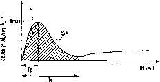
相反,图7显示了其中当在触板10上的键盘上敲击键时接触区域A的大小变化的另一个示例。在此情况下,接触区域A的大小从0或基本上为0快速提高到最大,然后快速降低。In contrast, FIG. 7 shows another example in which the size of the contact area A changes when a key is struck on the keyboard on the
可以根据对象在接触检测层10a上的接触压力或接触压力的与时间有关的变化来检测接触强度。在此情况下,将压力转换为电信号的传感器可以被用作接触检测层10a。The contact intensity can be detected from the contact pressure of the object on the
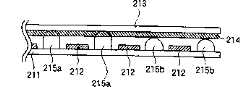
图8A和图8B显示了作为将压力转换为电信号的传感器的触板210(称为“接触强度检测器”)。8A and 8B show a touch panel 210 (referred to as a "contact strength detector") as a sensor that converts pressure into an electrical signal.
请参看这些图,触板210包括基底211和基底213。给基底211提供多个(即,n个)充当X电极并在X方向间隔相等的透明的电极条带212(称为“X电极212”)。给基底213提供多个(即,m个)充当Y电极并在Y方向间隔相等的透明的电极条带214(称为“Y电极214”)。基底211和213层叠在一起,X和Y电极212和214彼此面对面。因此,在X和Y电极212和214的交叉点处有(nXm)个接触检测器210b到210d呈现矩阵的形状。Referring to these figures, the
此外,多个点垫片215设置在基底211上的X电极212之间,并具有大于X和Y电极212和214的总厚度的高度。点垫片215的顶部与暴露在Y电极214之间的基底213接触。In addition, a plurality of dot spacers 215 are disposed between the
请参看图8A,在点垫片215中,四个高的点垫片215a构成一个组,四个矮的点垫片215b构成一个组。四个高的点垫片215a的组和四个矮的点垫片215b的组以网状的模式排列,如图8B所示。可以根据需要来确定每个组的高的点垫片215a的数量和每个组的矮的点垫片215b的数量。Referring to FIG. 8A , among the dot pads 215 , four
请参看图8C,点垫片215被夹在基底211和213之间。因此,X和Y电极212和214不相互接触。因此,接触检测器210b到210e不通电。Referring to FIG. 8C , dot spacers 215 are sandwiched between
当基底213弯曲而前述的电极不相互接触时,X和Y电极212和214处于通电状态。When the
对于触板210,与Y电极214所在的基底213的表面相对的表面213A被作为输入表面暴露出来。当表面213A被用户的手指按压时,基底213弯曲,从而使Y电极214与X电极212接触。For the
如果用户的手指施加的压力等于或小于第一预定压力,则基底213不充分弯曲,这会防止X和Y电极214和212彼此进行接触。If the pressure applied by the user's finger is equal to or less than the first predetermined pressure, the
相反,当施加的压力大于第一预定压力时,基底213充分弯曲,以便由四个低的点垫片215b(彼此相邻,而不通过Y和X电极214和212)围绕的接触检测器210b处于通电状态。由两个或更多高的点垫片215a围绕的接触检测器210c和210d仍保持断电状态。Conversely, when the applied pressure is greater than the first predetermined pressure, the
如果施加的压力大于第二预定压力,则基底213进一步弯曲,由两个低的点垫片215b围绕的接触检测器210c处于通电状态。然而,由四个高的点垫片215a围绕的接触检测器210d仍保持断电状态。If the applied pressure is greater than the second predetermined pressure, the
此外,如果施加的压力大于第三预定压力(该预定压力大于第二压力),则基底213更加弯曲,以便由四个高的点垫片215a围绕的接触检测器210d处于通电状态。In addition, if the applied pressure is greater than a third predetermined pressure, which is greater than the second pressure, the base 213 bends more so that the
在用户的手指按压的区域中存在三个接触检测器210b到210d,其用于将检测到的压力转换为三种电信号的传感器。There are three
对于包括触板210的便携式微电脑,接触检测单元21检测哪一个接触检测器处于通电状态。For a portable microcomputer including the
例如,接触检测单元21检测由一组处于通电状态的相邻接触检测器围绕的接触检测器,作为接触检测表面10a被按压的位置。For example, the
此外,接触检测单元21在一组处于通电状态的相邻接触检测器中将接触检测器210b到210d分为三个等级,最高的等级被作为压力输出。Furthermore, the
接触检测单元21按如下方式检测接触区域和压力分布。The
当如图8B所示的低的和高的点垫片215b和215a按如图9所示的方式排列时,每一个接触检测器210都由四个点垫片围绕。在图9中,数字代表对应于接触检测器210a到210d的位置处的高的点垫片215a的数量。When the low and
在图10中,椭圆显示了被用户的手指接触的区域,并叫做“外椭圆”。In FIG. 10, the ellipse shows the area touched by the user's finger and is called "outer ellipse".
当接触区域的表面压力(即,单位面积的压力)只是足以按下“0”所示的接触检测器时,接触检测单元21检测到只有接触检测器“0”(即,如图8B所示的接触检测器210b)被按压。When the surface pressure (that is, the pressure per unit area) of the contact area is only enough to press the contact detector shown in "0", the
如果与如图9所示的压力相比向其大小与外椭圆的大小相同的区域施加大得多的压力,接触检测单元21检测存在于外椭圆的椭圆内部(称为“内椭圆”)中的接触检测器“2”,即,如图8B所示的接触检测器210c被按压。If a much greater pressure is applied to an area whose size is the same as that of the outer ellipse than that shown in FIG. The contact detector "2", that is, the
压力越大,参考本实施例的操作原理描述的外椭圆就越大。然而,为了便于说明,假设外椭圆具有稳定的大小。The greater the pressure, the larger the outer ellipse described with reference to the operating principle of this embodiment. However, for ease of illustration, assume that the outer ellipse has a constant size.
然而,实际上,表面压力并不总是以如图11所示的椭圆的形状那样分布。在图12中,可以检测到外椭圆外部的某些接触检测器被按压,内椭圆内部的某些接触检测器“0 ”或“2 ”可能不会被检测到被按压。图12中以斜体数字描述了那些例外。简而言之,接触检测器“0”和“2”在外椭圆和内椭圆的边界处混合。确定外椭圆和内椭圆的边界、大小、形状或位置,以便减少由这些因素所引起的错误。在这样的情况下,外椭圆和内椭圆的边界可能是复杂的,以便确保灵活性。然而,边界实际上是具有适当的曲率半径的形状。这使得边界具有平滑变化的轮廓,并且相对来说没有错误。曲率半径是通过实验、机器学习算法等等确定的。目标函数是在键入时由外椭圆和内椭圆围绕的区域的大小,由内椭圆和最里边的椭圆围绕的区域的大小,以及与时间有关的键入识别错误率。确定最小曲率半径,以便最小化前述的参数。However, in reality, the surface pressure is not always distributed in the shape of an ellipse as shown in FIG. 11 . In Figure 12, some contact detectors outside the outer ellipse can be detected to be pressed, and some contact detectors "0" or "2" inside the inner ellipse may not be detected to be pressed. Those exceptions are described in italicized numbers in Figure 12. In short, contact detectors "0" and "2" blend at the boundary of the outer and inner ellipses. Determine the boundary, size, shape, or position of the outer and inner ellipses to reduce errors caused by these factors. In such cases, the boundaries of the outer and inner ellipses may be complex in order to ensure flexibility. However, the boundary is actually a shape with an appropriate radius of curvature. This makes the boundaries have smoothly changing contours and are relatively error-free. The radius of curvature is determined through experiments, machine learning algorithms, and the like. The objective functions are the size of the area surrounded by the outer ellipse and the inner ellipse, the size of the area surrounded by the inner ellipse and the innermost ellipse while typing, and the time-dependent typing recognition error rate. The minimum radius of curvature is determined so as to minimize the aforementioned parameters.
上文所提及的边界确定方法适用于如图10、图11、图13和图14所示的情况。The boundary determination method mentioned above is applicable to the situations shown in FIG. 10 , FIG. 11 , FIG. 13 and FIG. 14 .
图13显示施加了比图11所示的压力大得多的压力。在此情况下,最里边的椭圆出现在内椭圆的内部。在第二内椭圆中,检测到“0”、“2”和“4”所示的接触检测器被被按压,即,图8B所示的接触检测器210b、210c和210d被按压。Figure 13 shows that a much greater pressure than that shown in Figure 11 was applied. In this case, the innermost ellipse appears inside the inner ellipse. In the second inner ellipse, it is detected that the contact detectors shown by "0", "2" and "4" are pressed, that is, the
参看图1 4,内椭圆和最里边的椭圆的尺寸被扩大。这意味着,施加了远大于图13的压力的压力。Referring to Figure 14, the size of the inner ellipse and the innermost ellipse is enlarged. This means that a pressure much greater than that of FIG. 13 is applied.
可以通过检测椭圆大小的与时间有关的变化和椭圆大小比率的与时间有关的变化,可靠地检测用户是有意按下了键还是无意地按下了键,如图10、图11、图13和图14所示。Whether the user pressed a key intentionally or accidentally can be reliably detected by detecting the time-dependent change in the size of the ellipse and the time-dependent change in the ratio of the ellipse sizes, as shown in Figures 10, 11, 13 and Figure 14 shows.
例如,使用将压力转换为电信号的传感器,根据接触压力的与时间有关的变化,检测对象与接触检测表面10a的接触压力或接触强度。如果图6和图7中的纵坐标变为“接触压力”,相对于“简单地放上对象”和“键命中”,将获得相同的结果。For example, using a sensor that converts pressure into an electrical signal, the contact pressure or contact intensity of the object with the
设备控制IC 23(作为确定部分)接收由接触检测单元21检测的接触强度,提取涉及接触强度的特征量,并将提取的特征量或基于提取的特征量计算出的值与预先确定的阈值进行比较,并确定对象的接触状态。接触状态可以分为“无接触”、“接触”或“键命中”。“无接触”代表没有东西与显示单元5上的图像接触;“接触”代表对象与显示单元5上的图像接触;“键命中”代表显示单元5上的图像被对象命中。稍后将参考图18和图19详细地描述接触状态的确定。The device control IC 23 (as a determination section) receives the contact intensity detected by the
用来判断接触状态的阈值是可调整的。例如,设备控制IC 23指示键20b(WEAK)、键20c(STRONG),以及显示阈值的水平的水平表20a。参阅图15。这里假设,水平表20a预先为状态“接触”和“键命中”设置了某些阈值。如果用户温和地击中图像,这样的键命中常常不被识别。在这样的情况下,按压“WEAK”按钮20b。设备控制IC 23根据显示面板5上的按钮20b的位置和接触检测单元21检测到的接触位置,判断是否按压了“WEAK”按钮20b。当识别出按钮20b被按压时,激励显示驱动器22,以便将水平表20a上指示的值向左移动,从而降低阈值。在此状态下,图像实际上没有被按下,而是压力只是被施加到图像上。为简单起见,用术语“键命中”来表示用户有意按下图像。或者,可以通过拖动靠近水平表20a的滑块20d来改变水平表20a上的指示。The threshold used to judge contact status is adjustable. For example, the device control IC 23 indicates a key 20b (WEAK), a key 20c (STRONG), and a
设备控制IC 23(作为通知部分)向主板30a(如图5所示)通知作为输入设备的被操作的键盘或鼠标以及从接触检测单元21接收到的接触状态。简而言之,将为了输入信息而按压的键的位置,或其上面简单地放置了对象的键的位置通知给主板30a。The device control IC 23 (as a notification section) notifies the
设备控制IC 23(作为运算单元)根据代表接触位置和指示输入设备的图像的中心之间的差别的矢量数据,导出用于校正显示单元上显示的输入设备的位置、大小或形状的值。此外,设备控制IC 23还根据用户信息导出用于校正显示单元上显示的输入设备的位置、大小或形状的量。这里,使用用户信息来识别用户,例如,可以使用用户的手掌的大小来识别用户。用户信息存储在存储器单元24中(如图4所示)。当输入设备是外部设备时,用户信息存储在输入设备所连接到的计算机的存储器单元中(如稍后所描述的图42到图44所示)。The device control IC 23 (as an arithmetic unit) derives values for correcting the position, size, or shape of the input device displayed on the display unit from the vector data representing the difference between the contact position and the center of the image indicating the input device. In addition, the device control IC 23 also derives an amount for correcting the position, size, or shape of the input device displayed on the display unit from user information. Here, the user is identified using user information, for example, the user may be identified using the size of the user's palm. User information is stored in the memory unit 24 (shown in FIG. 4). When the input device is an external device, user information is stored in a memory unit of a computer to which the input device is connected (as shown in FIGS. 42 to 44 described later).
假设以键盘作为输入设备。当在键盘上输入包含N个字符的字符串S时,设备控制IC 23(运算单元)计算二维坐标变换T,该二维坐标变换T用来最小化用户输入的包含N个字符的预先确定的字符串S的坐标集U以及字符串S的中心坐标集C′(这是通过向使用当前键盘布局输入的字符串S的中心坐标集C应用二维坐标变换T获得的)之间的总的差。运算单元根据中心坐标集C′确定新的键盘布局。Assume the keyboard is used as the input device. When a character string S comprising N characters is input on the keyboard, the device control IC 23 (computing unit) calculates a two-dimensional coordinate transformation T, which is used to minimize a predetermined value of N characters input by the user. The total between the coordinate set U of the string S and the central coordinate set C′ of the string S (which is obtained by applying a two-dimensional coordinate transformation T to the central coordinate set C of the string S input using the current keyboard layout) poor. The arithmetic unit determines a new keyboard layout according to the central coordinate set C'.
根据键信息,设备控制IC 23进一步修改键盘布局,并对键的位置、形状和角度进行微调。微调间隔将被设置为某一值。当对象接触到某一键时,设备控制IC 23指示代表用于输入前一数据的输入设备(数据存储在存储器24中)的图像。According to the key information, the device control IC 23 further modifies the keyboard layout, and fine-tunes the positions, shapes and angles of the keys. The nudge interval will be set to a certain value. When an object touches a certain key, the device control IC 23 indicates an image representing an input device (data stored in the memory 24) for inputting the previous data.
设备控制IC 23(作为求和单元)把当以键盘作为输入设备时的中心键命中率或目标键命中率相加。中心键命中率表示键的中心被命中的比率,而目标键的命中率表示所希望的键被命中的比率。The device control IC 23 (as a summing unit) adds up the center key hit rate or the target key hit rate when the keyboard is used as the input device. The center key hit ratio indicates a rate at which the center of a key is hit, and the target key hit rate indicates a rate at which a desired key is hit.
当在触板10的接触检测表面10a上垂直地或倾斜地接触到对象时(如图31所示),设备控制IC 23(作为校正单元)调整显示面板上指示的输入设备的位置。此外,当对象被倾斜地接触时,设备控制IC 23使用接触位置和输入图像的参考位置之间的差别来调整输入设备的位置。When an object is contacted vertically or obliquely on the
图4所示的设备控制IC 23(作为显示控制器)根据接触检测层10a上的对象的接触状态(“无接触”、“接触”或“键命中”),改变显示单元5上的图像的指示模式。具体来说,设备控制IC 23根据接触状态,改变轮廓线(profile line)的亮度、颜色配置文件、模式和厚度、闪烁/稳定的发光、图像的闪烁间隔。The device control IC 23 shown in FIG. 4 (as a display controller) changes the image on the
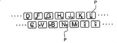
这里假设,显示单元5显示了虚拟键盘,并且用户将要输入信息。请参阅图16。用户将他的或她的手指放在初始位置以便开始击键。在此状态下,用户的手指位于键“S”、“D”、“F”、“J”、“K”和“L”上。设备控制IC 23用黄色照亮前述的键。例如,设备控制IC 23用蓝色照亮其余的无接触键。在图17中,例如,当用户击中键“O”时,设备控制IC 23用红色照亮键“O”。键“S”、“D”、“F”和“J”仍是黄色,这意味着用户的手指位于这些键上。It is assumed here that the
如果不总是需要识别“无接触”、“接触”和“键命中”,则用户可以选择接触状态以便改变指示模式。If it is not always necessary to recognize "no contact", "contact" and "key hit", the user may select the contact state in order to change the indication mode.
此外,设备控制IC 23还在显示单元5上显示对象的轮廓。例如,可以在显示单元5上显示用户的手掌的轮廓(在图16中用短划线显示)。此外,设备控制IC 23还沿着用户的手掌的轮廓将鼠标显示为输入设备。In addition, the device control IC 23 also displays the outline of the subject on the
此外,设备控制IC 23还可以用作为发声部分,基于接触检测部分21检测到的位置和虚拟键盘或鼠标的图像的位置之间的关系,根据接触状态,判断预先确定的识别声音,控制扬声器驱动器25,并通过扬声器26发出识别声音。例如,假设在显示单元5上显示了虚拟键盘,用户可以敲击一个键。在此状态下,设备控制IC 23计算接触检测单元21检测到的键和显示单元5上显示的键的中心的相对位置。稍后将参考图21到图23详细描述此计算过程。In addition, the device control IC 23 can also be used as a sound generating part, based on the relationship between the position detected by the
当敲击键,并发现被命中的键的指示的位置与其中心之间的相对距离大于预先确定的值时,设备控制IC 23激励扬声器驱动器25,从而产生通知声音。该通知声音可以具有不同于为普通“键命中”发出的识别声音的音调、时间间隔、模式等等。When a key is struck, and the relative distance between the indicated position of the hit key and its center is found to be greater than a predetermined value, the device control IC 23 activates the speaker driver 25, thereby generating a notification sound. The notification sound may have a different pitch, time interval, pattern, etc. than the recognition sound made for a normal "key hit".
这里假设,用户使用显示单元5上的虚拟键盘来输入信息。用户预先记录了初始位置。如果用户将他的或她的手指放在初始位置键之外的键上,则设备控制IC 23识别出该初始位置键之外的键与用户的手指接触,并可以发出不同于在用户接触初始位置键时发出的声音的另一个通知声音(例如,音调、时间间隔或模式)。It is assumed here that the user inputs information using a virtual keyboard on the
发光单元27位于输入设备上,并根据由设备控制IC 23确定的接触状态发光。例如,当识别出用户将他的或她的手指放在初始位置键上时,设备控制IC 23使发光单元27发光。The
存储器24(如4图所示)存储了有关对象的接触位置和接触强度的数据,以及代表了接触位置和显示输入设备的图像的中心之间的差别的矢量数据。The memory 24 (shown in FIG. 4) stores data on the contact position and contact intensity of the object, and vector data representing the difference between the contact position and the center of the image displayed on the input device.
此外,存储器24还存储了代表由接触检测器21检测到的位置和键盘上的键的中心之间的差别的矢量数据。存储器24还存储了有关删除键被命中的次数的数据,以及涉及紧随在删除键之后被命中的键的类型的数据。In addition, the
更进一步,存储器24还存储了在其上面接触了对象的输入设备的图像以及由触板10识别的用户信息,并且这两者彼此对应。Still further, the
存储器24存储了预先确定的时间段内对象的接触位置和接触强度的历史。存储器24可以是随机存取存储器(RAM)、诸如闪存之类的非易失性存储器、诸如硬盘或软磁盘之类的磁盘、诸如压缩光盘之类的光盘、IC芯片、盒式磁带,等等。The
本实施例的输入设备20包括通过使用至少图形、字母、符号或灯光指示器来指示界面状态(接触、键命中、手的位置、自动调整、用户的姓名,等等)的显示单元。此显示单元可以是显示单元5,也可以是一个单独的部件。The
下面描述如何存储各种信息处理程序。输入设备20在存储器24中存储了信息处理程序,这些程序使接触位置检测单元21和设备控制IC 23检测接触位置和接触强度,判断接触状态,进行自动调整,启用打字练习,进行重新键入调整,指示鼠标的操作,进行视野校正,等等。输入设备20包括信息阅读器(没有显示),以便将前述的程序存储在存储器24中。信息阅读器从诸如软磁盘之类的磁盘、光盘、IC芯片或诸如盒式磁带之类的记录介质获取信息,或从网络下载程序。当使用记录介质时,可以轻松地存储、携带或销售程序。How to store various information processing programs is described below. The
通过执行存储在存储器24中的程序的设备控制IC 23等等来处理输入信息。请参阅图18到图23。根据信息处理程序,执行信息处理步骤。Input information is processed by the device control IC 23 and the like executing programs stored in the
假设用户使用输入单元3的显示单元5上显示的虚拟键盘来输入信息。Assume that the user inputs information using the virtual keyboard displayed on the
在图18所示的步骤中对信息进行处理。在步骤S101中,输入设备20在显示单元5上显示了输入设备的图像(即,虚拟键盘)。在步骤S102中,输入设备20接收触板10的接触检测层10a上的检测区域的数据,并判断是否有与诸如用户的手指之类的对象接触的检测区域。当没有与对象接触的区域时,输入设备20返回到步骤S102。否则,输入设备20转到步骤S104。Information is processed in the steps shown in FIG. 18 . In step S101 , the
输入设备20在步骤S104中检测对象与接触检测层10a接触的位置,并在步骤S105中检测接触强度。The
在步骤S106中,输入设备20提取对应于检测到的接触强度的特征量,将提取的特征量或使用该特征量计算出的值与预先确定的阈值进行比较,并识别虚拟键盘上的对象的接触状态。如上所述,接触状态可以分为“无接触”、“接触”或“键命中”。图7显示了“键命中”,即,接触区域A起初基本上为零,然后突然增大。此状态被认为是“键命中”。具体来说,提取接触区域的大小作为特征量,如图6和图7所示。使用接触区域的大小导出面积速度或面积加速度,即,计算出特征量ΔA/Δt或Δ2A/Δt2。当此特征量大于阈值时,则判断接触状态为“键命中”。In step S106, the
特征量ΔA/Δt或Δ2A/Δt2的阈值取决于用户或正在使用的应用程序,或也可以随着时间逐渐变化,即使同一个用户反复地对输入单元进行操作。代替使用预先确定的和固定的阈值,将在适当的时间学习阈值,并对其进行重新校准,以便提高接触状态的准确识别。The threshold value of the feature quantity ΔA/Δt or Δ2 A/Δt2 depends on the user or the application being used, or may gradually change over time even if the same user repeatedly operates the input unit. Instead of using predetermined and fixed thresholds, thresholds will be learned at appropriate times and recalibrated to improve accurate identification of contact states.
在步骤S107中,输入设备20判断是否进行敲击键的操作。如果否,则输入设备20返回到步骤S102,并获取检测区域的数据。在“键命中”的情况下,输入设备20转到步骤S108,并将有关“键命中”的情况通知给计算机主单元30。在此状态下,输入设备20还返回到步骤S102,并获取后一接触状态检测的检测区域的数据。并行地执行前述的过程。In step S107, the
在步骤S109中,输入设备20改变虚拟键盘上的指示模式,以便指示“键命中”,例如,改变被命中的键的轮廓线的亮度、颜色、形状、模式或厚度,或键的闪烁/稳定的发光,或闪烁/稳定的发光间隔。此外,输入设备20检查预先确定的时间段的流逝。如果否,则输入设备20维持当前的指示模式。否则,输入设备20将虚拟键盘的指示模式返回到正常状态。或者,输入设备20可以判断被命中的键是否闪烁了预先确定的次数。In step S109, the
在步骤S110中,输入设备20发出识别声音(即,报警)。稍后将参考图21详细地描述此过程。In step S110, the
图19显示了步骤S106中的“键命中”的过程。FIG. 19 shows the process of "key hitting" in step S106.
首先,在步骤S1061中,输入设备20提取多个变量(特征量)。例如,根据图7所示的图形提取下列各项:接触区域的最大尺寸Amax,通过对接触区域A进行积分所导出的接触区域A的瞬时大小SA,接触区域的最大尺寸之前的时间TP,以及从开始到结束的键命中的总时长Te。根据前述的特征量,计算上升梯度k=Amax/TP等等。First, in step S1061, the
特征量的前述的定性的和物理特征显示了下列趋势。用户的手指越粗,击键越有力,接触区域的最大尺寸Amax就越大。击键越有力,接触区域A的瞬时大小SA就越大。用户的手指越软,击键越有力,越慢,到接触区域TP的最大尺寸的时间就越长。击键速度越慢,用户的手指越软,总时长Te就越长。此外,击键越快,越有力,用户的手指越硬,上升梯度k=Amax/TP就越大。The foregoing qualitative and physical characteristics of the characteristic quantities show the following tendencies. The thicker the user's finger is, the stronger the keystroke is, and the larger the maximum size Amax of the contact area is. The harder the keystroke, the greater the instantaneous size SA of the contact area A. The softer the user's finger, the harder and slower the keystroke, the longer the time to reach the maximum size of the contact area TP . The slower the keystroke speed and the softer the user's fingers, the longer the total time Te is. In addition, the faster and more powerful the keystroke, the harder the user's finger is, and the greater the ascending gradient k=Amax /TP.
特征量通过对相应的用户的多个击键的时间求平均值来导出,并用于识别键命中。累积只有关识别的键命中的数据,并对其进行分析。此后,设置阈值,以便识别键命中。在此情况下,统计用户取消键命中。The feature quantity is derived by averaging the times of a plurality of keystrokes of the corresponding user and used to identify a key hit. Accumulates data only about identified key hits and analyzes them. Thereafter, a threshold is set so that key hits are identified. In this case, user cancel key hits are counted.
对于所有键,可以测量特征量。有时,对于每个手指、每个键,或每组键,可以通过测量特征量来改善识别键命中的准确度。For all keys, characteristic quantities can be measured. Sometimes, for each finger, each key, or each group of keys, the accuracy of identifying key hits can be improved by measuring feature quantities.
对于前述的变量,可以确定单独的阈值。根据条件分支,例如,当一个或多个变量超过预先确定的阈值时,可以识别键命中。或者,可以使用诸如多元分析技术之类的更先进的技术来识别键命中。For the aforementioned variables, separate thresholds can be determined. Based on conditional branching, key hits can be identified, for example, when one or more variables exceed predetermined thresholds. Alternatively, more advanced techniques such as multivariate analysis techniques can be used to identify key hits.
例如,记录多个键命中时间。根据指定的多元数据集,学习马哈拉诺比斯空间。使用马哈拉诺比斯空间,计算键命中的马哈拉诺比斯距离。马哈拉诺比斯距离越短,识别键命中就越准确。请参阅“TheMahalanobis-Taguchi System,ISBN0-07-136263-0,McGraw-Hill”,等等。For example, logging multiple key hit times. Learns a Mahalanobis space from a given multivariate dataset. Using the Mahalanobis space, compute the Mahalanobis distance for key hits. The shorter the Mahalanobis distance, the more accurate the identification of key hits. See "The Mahalanobis-Taguchi System, ISBN 0-07-136263-0, McGraw-Hill", etc.
具体来说,在图19所示的步骤S1062中,对于多元数据中的每一个变量,计算平均和标准偏差。使用平均和标准偏差,对原始数据进行z变换(此过程叫做“标准化”)。然后,计算变量之间的相关系数,以便导出相关矩阵。有时,当收集了初始的键命中数据时,此学习过程只执行一次,并且不更新。然而,如果用户的击键习惯改变,如果输入设备在机械方面或电的方面老化,或者如果击键的识别准确度由于某种原因而降低,将重新学习,以便提高识别准确度。当多个用户登录时,对于每一个用户,可以提高识别准确度。Specifically, in step S1062 shown in FIG. 19 , for each variable in the multivariate data, the mean and standard deviation are calculated. Using the mean and standard deviation, z-transform the raw data (this process is called "normalization"). Then, the correlation coefficients between the variables are calculated in order to derive the correlation matrix. Sometimes, this learning process is performed only once, when the initial key hit data is collected, and is not updated. However, if the user's keystroke habits change, if the input device ages mechanically or electrically, or if the recognition accuracy of the keystrokes decreases for some reason, it will be relearned to improve the recognition accuracy. When a plurality of users are logged in, for each user, recognition accuracy can be improved.
在步骤S1063中,使用平均、标准偏差和一组相关矩阵,计算要识别的键命中数据的马哈拉诺比斯距离。In step S1063, the Mahalanobis distance of the key hit data to be identified is calculated using the mean, standard deviation and a set of correlation matrices.
在步骤S1064中识别多元数据(特征量)。例如,当马哈拉诺比斯距离小于预先确定的阈值时,对象被识别为处于“键命中”状态。Multivariate data (feature amounts) are identified in step S1064. For example, when the Mahalanobis distance is less than a predetermined threshold, the object is identified as being in a "key hit" state.
当利用其中马哈拉诺比斯距离越短,可以越可靠地识别键命中的算法时,与特征量被用于用户标识的情况相比,可以进一步提高用户标识。这是因为,当利用马哈拉诺比斯距离时,进行识别(即,模式识别),其中考虑所学习的变量之间的关联。即使峰值Amax基本上近似于键命中数据的平均值,但接触区域的最大尺寸之前的时间Tp长,也将准确地识别键命中之外的接触状态。When using an algorithm in which the shorter the Mahalanobis distance, the more reliably the key hit can be identified, user identification can be further improved compared to the case where feature quantities are used for user identification. This is because, when utilizing the Mahalanobis distance, recognition (ie, pattern recognition) is performed in which associations between the variables being learned are considered. Even if the peak value Amax substantially approximates the average value of the key hit data, but the time Tp before the maximum size of the contact area is long, the contact state other than the key hit will be accurately identified.
在本实施例中,根据其中利用了马哈拉诺比斯空间的算法来识别键命中。不用说,可以使用其他多元分析算法来识别多个变量。In the present embodiment, a key hit is identified according to an algorithm in which a Mahalanobis space is utilized. It goes without saying that other multivariate analysis algorithms can be used to identify multiple variables.
下面参考图20描述改变用于指示“无接触”和“接触”状态的指示模式的过程。The process of changing the indication mode for indicating the "non-contact" and "contact" states will be described below with reference to FIG. 20 .
步骤S201和S202与图18所示的步骤S101和S102相同,将不再赘述。Steps S201 and S202 are the same as steps S101 and S102 shown in FIG. 18 , and will not be repeated here.
在步骤203中,输入设备20判断接触检测层10a是否被对象接触。如果否,输入设备20转到步骤S212。否则,输入设备20进入步骤S204。在步骤S212中,输入设备20识别键处于虚拟键盘上的“无接触”状态,并改变键指示模式(以指示“备用状态”)。具体来说,通过改变不同于“接触”或“键命中”状态的轮廓线的亮度、颜色、形状、模式或厚度来指示无接触状态。输入设备20返回到步骤S202,并获取有关检测区域的数据。In step 203, the
步骤S204到S206与步骤S104到S106相同,这里将不再赘述。Steps S204 to S206 are the same as steps S104 to S106 and will not be repeated here.
当在步骤S207中没有识别键命中时,输入设备20转到步骤S213。在步骤S213中,输入设备20识别出对象与虚拟键盘上的键接触,并将指示模式改变为用于“接触”状态的指示模式。输入设备20返回到步骤S202,并获取有关检测到的区域的数据。当识别键命中时,输入设备20转到步骤S208,然后返回到步骤S202,以便识别后一状态,并接收有关检测区域的数据。When the key hit is not recognized in step S207, the
步骤S208到S211与步骤S108到S111相同,这里将不再赘述。Steps S208 to S211 are the same as steps S108 to S111 and will not be repeated here.
在步骤S110中(如图18所示),如果实际上命中的键的位置不同于在输入设备(即,虚拟键盘)上指示的图像,则产生报警。In step S110 (as shown in FIG. 18 ), if the position of the actually hit key is different from the image indicated on the input device (ie, the virtual keyboard), an alarm is generated.
请参阅图21,在步骤S301中,输入设备20获取键命中标准坐标(例如,基于被命中的键的接触检测器10b的坐标组估计的重心坐标)。Referring to FIG. 21 , in step S301 , the
接下来,在步骤S302中,输入设备20将键命中标准坐标和虚拟键盘上被命中的键的标准坐标(例如,中心坐标)进行比较。计算下列值:键命中标准坐标和标准坐标之间的偏差(叫做“键命中偏差矢量”),即,在键命中标准坐标和被命中的键的标准坐标之间延伸的x和y平面上的方向和长度。Next, in step S302, the
在步骤S303中,输入设备20识别在虚拟键盘上的每一个键顶上,被命中键的坐标位于哪一部分。键顶可以分成两个或五个部分,如图22和图23所示。用户可以判断键顶上的各个部分。图22和图23所示的部分55是键被准确地命中的位置。In step S303, the
输入设备20根据被识别的部分确定识别声音。具有不同音调、时间间隔或模式的识别声音用于图22和图23所示的部分51到55。The
或者,输入设备20可以根据键命中偏差矢量的长度来改变识别声音。例如,键命中偏差矢量越长,识别声音具有的强度就越高。根据键命中偏差矢量的方向,可以改变间隔或音调。Alternatively, the
如果用户接触一个键顶的两个部分,可以产生中间声音,以便代表两个部分。或者,可以根据被接触部分的相应的大小,产生内部声音。对于较大的部分,可以产生声音,或者,也可以作为和音发出两个声音。If the user touches two parts of one key top, an intermediate sound may be produced so as to represent the two parts. Alternatively, the internal sound may be generated according to the corresponding size of the contacted portion. For larger parts, a sound can be produced, or two voices can be produced as a chord.
在步骤S305中,输入设备20以预先确定的音量来产生所选择的识别声音。输入设备20还检查预先确定的时间段的流逝。如果否,则连续地产生识别声音。否则,输入设备20停止识别声音。In step S305, the
相对于步骤S304,为部分51到55提供不同的识别声音。或者,部分55的识别声音可以不同于部分51到54的识别声音。例如,当命中部分55时,输入设备20识别适当的键命中,并产生不同于其他部分的识别声音的识别声音。或者,在此情况下不产生声音。Different recognition sounds are provided for the
用户可以根据部分55在键顶上的百分比或比率按需要确定部分55的大小或形状。此外,可以基于命中比率,或键命中偏差矢量的x和y分量的分布,自动确定部分55。The user can determine the size or shape of the
或者,根据被命中的部分是在部分55之内还是在部分55之外,可以为部分51到54产生不同的识别声音。Alternatively, different recognition sounds may be generated for
所有键的部分55可以被独立地或同时调整,或者,可以将键分成多个组,将对其中每一个组分别进行调整。例如,主要键的键命中偏差矢量可以累积成一个块。可以同时改变这样的键的形状和大小。
自动调整过程:Auto-tuning process:
下面将描述自动调整过程。在此过程中,参考图24,根据键盘上指示的键和输入位置之间的差别,调整键的位置、大小和形状。可以对于每一个键分步骤地、对于所有键共同地,或为键组单独地执行此调整过程。例如,可以以这样的方式设计该过程,以便对于一组主要键可以累积键命中偏差矢量,并且可以同时改变用于改变主要键的形状或大小的参数。The automatic adjustment process will be described below. In this process, referring to FIG. 24 , according to the difference between the key indicated on the keyboard and the input position, the position, size, and shape of the key are adjusted. This adjustment process can be performed in steps for each key, collectively for all keys, or individually for groups of keys. For example, the process can be designed in such a way that key hit deviation vectors can be accumulated for a set of primary keys, and parameters for changing the shape or size of the primary keys can be varied at the same time.
步骤S401中的键命中偏差矢量与图21所示的步骤S302中的方式相同,这里将不再进行描述。输入设备20将键命中偏差矢量数据存储在存储器5中。The key hit deviation vector in step S401 is the same as that in step S302 shown in FIG. 21 , and will not be described again here. The
在步骤S402中,输入设备20检查在预先确定的时间是否命中了键盘上的每一个键或每一组键。可以累积键命中间隔。根据过去的n次键命中的数据导出的调整参数,可以用于每一个键命中(“n”是一个自然数)。如果“n”被设置为适当的数字,则每次命中键时,前面的算法可以优化键盘的布局、形状或大小。此外,可以避免由于布局、形状或大小的急剧变化而造成的难以使用输入设备或感觉不适的问题。In step S402, the
在步骤S403中,输入设备20采用键命中偏差量的分布,并计算最佳分布。然后,在步骤S404中,输入设备20根据分布变化数据来计算用于定义分布的形状的一个或多个参数。In step S403, the
在步骤S405中,输入设备20改变要显示的键盘的位置、大小和形状等等(输入范围)。In step S405, the
在步骤S406中,输入设备20判断是否完成调整过程。如果调整过程没有完成,输入设备重复步骤S401到S405。In step S406, the
用户可能希望知道输入设备20执行的调整过程的当前状态。当提供前面的算法时,输入设备20可以被设计为在输入设备或在显示单元上指示“存储键命中偏差”、“自动调整在进行中”或“不在进行自动调整”。The user may wish to know the current status of the adjustment process performed by the
下面描述如何为用户确定用于最佳键盘模式的参数。在此情况下,在显示单元上没有显示键盘的图像。当输入预先确定的字符串(即,密码)时,则识别出用户具有输入数据的意图。输入设备20计算所采用的用户的键距。请参阅图25。The following describes how to determine the parameters for the best keyboard mode for the user. In this case, no image of the keyboard is displayed on the display unit. When a predetermined character string (ie, password) is input, it is recognized that the user has an intention to input data. The
除了键距之外,通过优化诸如字符的布局、字符串的基线的倾斜,以及基线的曲度之类的布局参数,可以为每一个用户设计最佳键盘布局。可以为每个用户优化键盘布局。In addition to the key pitch, by optimizing layout parameters such as the layout of characters, the inclination of the baseline of character strings, and the curvature of the baseline, an optimum keyboard layout can be designed for each user. Keyboard layouts can be optimized for each user.
此外,根据用户如何输入密码,输入设备20可以识别用户希望使用哪一个键盘,例如,具有“QWERY”或“DVORAK”的顺序的字符排列的键盘。In addition, according to how the user enters the password, the
在步骤S501中(如图25所示),输入设备20获取有关用户敲击的键的坐标的数据,并将所获得的坐标与字符的预先确定的坐标进行比较(步骤S502)。In step S501 (as shown in FIG. 25 ), the
在步骤S503中,导出代表被命中的键的坐标和字符的预先确定的坐标之间的差别的微分矢量组。该微分矢量组包括对应于所输入的字符(构成了密码)的矢量。根据只由相应的微分矢量的开始点组成的开始点组以及只由相应的微分矢量的终点组成的终点组,并使用最小平方法创建一次直线。In step S503, a differential vector group representing the difference between the coordinates of the hit key and the predetermined coordinates of the character is derived. The set of differential vectors includes vectors corresponding to the entered characters (constituting the password). From a start point group consisting only of the start points of the corresponding differential vectors and an end point group consisting only of the end points of the corresponding differential vectors, a straight line is created once using the method of least squares.
y=a1x+b1y=a1 x+b1
y=a2X+b2y=a2 X+b2
在步骤S504中,比较a1和a2。因此,检查当敲击键时用户偏离xy平面中的参考点多少。计算角度校正量。否则,将密码中的字符分成其中字符在一条线上可以具有相同y坐标的多个组。因此,对x方向的角度求平均。当密码字符处于一条线上时,照原样利用平均角作为角度校正量。In step S504, a1 and a2 are compared. Therefore, it is checked how much the user deviates from the reference point in the xy plane when hitting the key. Calculates the angle correction. Otherwise, split the characters in the password into groups where characters can have the same y-coordinate on a line. Therefore, the angles in the x direction are averaged. When the cipher characters are on a line, the average angle is used as it is as the angle correction amount.
接下来,在步骤S505中,将开始点组的键盘标准位置与根据终点组估计的键盘标准位置进行比较,从而计算出用于校正x间距和y间距的量。为进行此计算,可以使用各种方法。例如,可以比较开始点组的坐标的中值点和终点组的坐标的中值点,从而导出x轴方向和y轴方向之间的差别。Next, in step S505, compare the keyboard standard position of the starting point group with the estimated keyboard standard position according to the end point group, so as to calculate the amount for correcting the x distance and the y distance. To perform this calculation, various methods can be used. For example, the median point of the coordinates of the start point group and the median point of the coordinates of the end point group may be compared to derive the difference between the x-axis direction and the y-axis direction.
在步骤S506中,单独地调整x方向中的延伸(kx)的步距和y方向中的延伸(ky)的步距,以便最小化开始点组和终点组的x坐标和y坐标之间的错误。此外,可以说明式地(使用数值计算方法以便最小化错误的平方和,也可以使用最小平方法以算术方式导出用于校正标准原点的量。In step S506, the step size of the extension (kx) in the x direction and the step size of the extension (ky) in the y direction are individually adjusted so as to minimize the distance between the x coordinates and the y coordinates of the start point group and the end point group mistake. Furthermore, the quantity for correcting the standard origin can be deduced either declaratively (using a numerical calculation method in order to minimize the sum of squares of the error, or mathematically using the method of least squares.
在步骤S507中,输入设备20对密码的字符串进行验证,即判断输入的密码是否与预先存储的密码一致。In step S507, the
在步骤S508中,输入设备20根据在步骤S504到S506中计算出的角度校正量、x间距和y间距校正量以及标准原点校正量,指示校正的输入范围(即,虚拟键盘25)。In step S508, the
分别进行步骤S504、S505和S506中的计算,以便将合适的变换T应用于当前键盘布局,从而将优选的键盘布局提供给用户。当前键盘布局可以与微电脑发货时提供的键盘布局相同,也可以是过去校正的键盘布局。The calculations in steps S504, S505 and S506 are performed respectively, so as to apply the appropriate transformation T to the current keyboard layout, so as to provide the user with a preferred keyboard layout. The current keyboard layout can be the same as the keyboard layout provided when the microcomputer shipped, or it can be a keyboard layout that has been corrected in the past.
或者,变换T也可以按如下方式导出。首先,请求用户敲击由N个字符组成的字符串S。将触板上的N个二维坐标(它们偏离键顶的中心的坐标)的集U与用于字符串S的键的键顶的中心的坐标C进行比较。如下面所描述的,将确定变换T,以便最小化前述的坐标之间的差别。此计算可以利用任何方法进行。二维坐标或二维矢量将通过″[x,y]″来表示。Alternatively, the transformation T can also be derived as follows. First, the user is requested to tap a character string S consisting of N characters. The set U of N two-dimensional coordinates on the touch panel (they are offset from the coordinates of the centers of the key tops) is compared with the coordinates C of the centers of the key tops for the keys of the character string S. As described below, the transformation T will be determined so as to minimize the difference between the aforementioned coordinates. This calculation can be done using any method. Two-dimensional coordinates or two-dimensional vectors will be represented by "[x,y]".
由N个二维坐标组成的集U表达为[xi,yi](i=1,2,...N)。变换T之后的中心坐标C′被表达为[ξi,ηi](i=1,2,...N)。通过坐标组的平行位移、旋转、膨胀或收缩来实现变换T。[e,f]表示代表平行位移的矢量。θ表示旋转角。λ表示扩大/收缩系数。可以根据当前键盘布局作为一个整体的中心点[a,b]以及U[c,d]=[(x1+x2…+xN)/N,(y1+y2…+yN)/N的平均坐标,来计算[e,f]=[c-a,d-b]。当根据旋转角θ和膨胀/收缩系数λ变换当前键盘布局时,变换后的坐标将是[ξi,ηi]=[λ{(Xi-e)cosθ-(Yi-f)sinθ},λ{(Xi-e)sinθ+(Yi-f)cosθ}],(i=1,2...N)。这里假设,θ和λ的初始条目分别被设置为0和1。使用顺序二次规划(SQP)方法,用数字方法导出参数θ和λ(它们最小化平方距离Δi=(ξi-xi)^2+(ηi-yi)^2)的和α=Δ1+Δ2+......ΔN。通过应用计算出的θ和λ而导出的变换的坐标集[ξi,ηi](i=1,2,...N)表示新的键盘布局。当变换的坐标集C′由于错误键入等等而具有大的误差界限,θ和λ可能不会变得收敛。在这样的情况下,不对字母串进行验证,也不应该调整键盘布局。因此,再次请求用户敲击用于字母串S的键。A set U consisting of N two-dimensional coordinates is expressed as [xi, yi] (i=1, 2, . . . N). The center coordinate C' after transformation T is expressed as [ξi, ηi] (i=1, 2, . . . N). The transformation T is achieved by a parallel displacement, rotation, expansion or contraction of the set of coordinates. [e,f] denotes a vector representing a parallel displacement. θ represents the rotation angle. λ represents an expansion/contraction coefficient. According to the current keyboard layout as a whole center point [a, b] and the average coordinates of U[c, d]=[(x1+x2...+xN)/N, (y1+y2...+yN)/N, to calculate [e, f] = [c-a, d-b]. When the current keyboard layout is transformed according to the rotation angle θ and the expansion/contraction coefficient λ, the transformed coordinates will be [ξi, ηi]=[λ{(Xi-e)cosθ-(Yi-f)sinθ}, λ{( Xi-e)sinθ+(Yi-f)cosθ}], (i=1, 2...N). It is assumed here that the initial entries of θ and λ are set to 0 and 1, respectively. Using the Sequential Quadratic Programming (SQP) method, numerically derive the parameters θ and λ (which minimize the sum of the squared distances Δi=(ξi-xi)^2+(ηi-yi)^2) α=Δ1+Δ2+. .....ΔN. The transformed coordinate set [ξi, ηi] (i = 1, 2, . . . N) derived by applying the calculated θ and λ represents a new keyboard layout. When the transformed coordinate set C' has a large margin of error due to typos and the like, θ and λ may not become converged. In such cases, the letter string is not validated and the keyboard layout should not be adjusted. Therefore, the user is requested to hit the key for the letter string S again.
或者,有时当分别在x和y方向调整λ时,可以实现更加优选的结果,以便可以优化横向间距和垂直间距。Alternatively, sometimes more preferable results can be achieved when lambda is adjusted in the x and y directions separately, so that lateral and vertical spacing can be optimized.
此外,当适当地设计变换T时,可以在其中以弯曲的状态排列了键的键盘、其中在分开的位置排列了通过左手敲击的一组键而通过右手敲击的一组键的键盘上调整键盘布局。In addition, when the transformation T is properly designed, it is possible on a keyboard in which keys are arranged in a bent state, a group of keys struck by the left hand and a group of keys struck by the right hand are arranged in separate positions Adjust the keyboard layout.
前述的布局调整可以单独地应用于由左右手敲击的键。可以应用前述的算法,以便以扇形异常地排列左手和右手键,如在市场上销售的某些计算机中那样。The aforementioned layout adjustments can be applied individually to keys struck by left and right hands. The aforementioned algorithm can be applied so that the left and right hand keys are unusually fanned out, as in some commercially available computers.
只在进行身份验证时才使用前述的校正。在显示单元上将不会显示经过校正的键布局,或者只有在进行间距调节的情况下才显示部分地经过校正或修改的键盘布局。当键偏离下外壳的边缘排列时,或者当它们不对称地排列时,用户可能会感觉到键盘使用起来不舒服。在这样的情况下,将不设置旋转角,或者对称地排列键。The aforementioned corrections are only used for authentication. The corrected key layout will not be displayed on the display unit, or a partially corrected or modified keyboard layout will only be displayed in the event of a spacing adjustment. When the keys are arranged offset from the edge of the lower case, or when they are arranged asymmetrically, users may find the keyboard uncomfortable to use. In such a case, no rotation angle will be set, or the keys will be arranged symmetrically.
通过应用如上所述的各种几何限制,键盘布局在其方便性和外表方面得到改善。By applying various geometric constraints as described above, keyboard layouts are improved in their convenience and appearance.
在前面的实施例中,输入设备20基于用户的手指、在接触检测表面上检测到的用户的信息(使这两者相互对应)存储输入设备的图像。当对象与显示单元上的输入设备的图像接触时,输入设备20可以基于用户的信息导出显示单元上的输入设备的图像的位置、大小或形状。例如,可以将检测表面10上检测到的用户的手的大小转换为代表手的大小的参数。然后,可以根据前述的参数改变输入设备的图像的大小。In the foregoing embodiments, the
如在图25所示的过程中那样,动态地调整键的大小和布局。然而,如果调整算法太复杂,或者如果有太多的调整参数,则键的大小和布局可能会变得难以使用,或者非可调参数会使得图像从可显示的区域跑偏(run off)。在图25所示的算法中,独立地调整(1)角度校正量,(2)x间距和y间距校正量,(3)参考点校正量。或者,在图19所示的算法之后,可以使用简单算法。在简单算法中,可以预先存储由一个或多个参数确定的键盘模式。只有x间距或y间距才可以相对于预先确定的键盘模式中的纵向和横向的大小来反映。As in the process shown in Figure 25, the size and layout of the keys is dynamically adjusted. However, if the tuning algorithm is too complex, or if there are too many tuning parameters, the key size and layout can become unwieldy, or non-tunable parameters can make the image run off from the displayable area. In the algorithm shown in FIG. 25, (1) angle corrections, (2) x-spacing and y-spacing corrections, and (3) reference point corrections are adjusted independently. Alternatively, following the algorithm shown in Figure 19, a simple algorithm can be used. In simple algorithms, keyboard patterns determined by one or more parameters can be pre-stored. Only the x-spacing or y-spacing can be reflected relative to the vertical and horizontal sizes in the predetermined keyboard mode.
利用前述的转换,可能不能灵活地调整参考位置的位移(例如,平行位移),以及布局。然而,用户在实践中可以对输入设备进行操作,而不会有任何问题,并且在进行各种不同的或复杂的操作时将不会遇到尴尬。With the aforementioned conversion, it may not be possible to flexibly adjust the displacement (for example, parallel displacement) of the reference position, as well as the layout. However, the user can operate the input device without any problems in practice and will not experience embarrassment when performing various or complex operations.
打字练习过程:Typing practice process:
下面将参考图26和图27描述打字练习过程。在此过程中,输入设备20为每个用户累积下列数据:表示用户是否敲击了每一个键的中心的中心键命中率或表示用户是否准确地击中他的或她的目标键的目标键的命中率。此过程提供了能使用户练习敲击具有低命中率的键的程序。The typing practice process will be described below with reference to FIGS. 26 and 27 . During this process,
在图26所示的步骤S601中,输入设备20指示用户输入打字练习代码,并识别用户在虚拟键盘25上输入了代码。In step S601 shown in FIG. 26 , the
在步骤S602中,输入设备20将输入位置和校正历史存储在存储器24中。In step S602 , the
输入设备20在步骤S603中计算中心键命中率或目标键的命中率。The
在步骤S604中,输入设备20设置一个参数,以便用图形方式显示中心键命中率或目标键的命中率的与时间有关的变化。In step S604, the
在步骤S605中,输入设备20显示了一个图形,如图27所示。In step S605, the
此外,输入设备20还对相应的键的分数进行排序,并可以要求用户集中地练习敲击具有低的分数的键。In addition, the
重新键入键的调整:Adjustments for retyping keys:
输入设备20根据诸如敲击删除键的次数、紧随在删除键之后重新键入的键类型之类的信息来执行用于重新键入的键的调整过程。在此过程中,输入设备20改变键盘布局或对键的位置、形状和角度进行微调,如图28所示。The
首先,在步骤S701中,输入设备20检测到用户在虚拟键盘5a上重新键入了一个字符。例如,输入设备20识别出用户敲击了QWERTY键盘上的“R”键,并使用删除键取消了“R”键,并重新键入“E”。First, in step S701, the
在步骤S702中,输入设备20计算错误地敲击了键的手指的中心与重新键入的键的中心的微分矢量数据。In step S702 , the
接下来,在步骤S703中,输入设备20导出过去错误地敲击的相关的键的次数的微分矢量数据的组。Next, in step S703 , the
在步骤S704中,输入设备20对该微分矢量数据组求平均值,并通过将平均微分矢量数据组与预先确定的系数相乘来计算校正量。如果系数等于或小于“1”,则校正量小。相反,如果系数近似于“1”,则校正量就大。系数越小,校正量就越小。此外,每当最近错误地敲击的键的平均次数大于预先确定的值时,都可以执行前述的校正,或者也可以当统计了预先确定的错误键入次数时周期性地执行该校正。In step S704, the
在步骤S705中,输入设备20根据校正量来校正被错误地敲击的键的位置,并在显示单元5a上显示被校正的键位置。In step S705, the
此外,输入设备20还可以判断用于对键盘布局进行微调的一个或多个间隔。In addition,
鼠标使用模式:Mouse usage mode:
请参看图29、图30A和图30B,当用户的手指处于“鼠标使用”姿势以便输入信息时,输入设备20在显示单元5a上显示虚拟鼠标5b。Referring to FIG. 29 , FIG. 30A and FIG. 30B , when the user's finger is in a "mouse use" posture for inputting information, the
在步骤S801中,输入设备20检测用户的手指在触板10上的接触形状。In step S801 , the
在步骤S802中,输入设备20识别鼠标使用姿势,并转到步骤S803。换句话说,用户的手指与触板10接触,如图30A中的阴影部分所示。In step S802, the
在步骤S803中,输入设备20记下虚拟鼠标5b的参考位置和参考角,并在显示单元5上显示虚拟鼠标5b,如图30B所示。判断参考位置位于用户的手指下面。在此状态下,虚拟鼠标5b可以重叠在键盘上,也可以擦除键盘来显示。In step S803, the
在步骤S804中,输入设备20检测到用户通过虚拟鼠标5b执行的点击、滑轮滚动等等。在步骤S805中,输入设备20获取有关移动量和使用虚拟鼠标5b执行的操作的数据。In step S804, the
以高速度重复步骤S801到S805中的过程,即,实时检测接触形状和鼠标使用姿势。当用户停止使用虚拟鼠标5b并从触板10移走他的或她的手时,以及恢复敲击键时,将立即显示或在预先确定的延迟之后显示键盘。The process in steps S801 to S805 is repeated at high speed, that is, the contact shape and the mouse use gesture are detected in real time. When the user stops using the
视野校准过程:Field of view calibration process:
下面将描述克服由用户的视角所引起的问题的视野校准过程。请参阅图31。假设用户查看显示单元5上的像素5c上的图像,并将要接触像素5c。如果用户垂直地向下看像素5c(使用眼睛240a),则用户与接触检测器10b1进行接触。相反,当用户斜着看像素5c(使用眼睛240b)时,用户与接触检测器10b2进行接触。如果用户就像对笔那样对对象进行操作以便垂直地与像素5c进行接触,则对象实际上与接触检测器10b1相接触,如图32所示。然而,当斜着看时,对象实际上接触到接触检测器10b2,如图33所示。A field of view calibration process that overcomes problems caused by the user's viewing angle will be described below. See Figure 31. Assume that the user views the image on the
在实际应用中,通过执行垂直校准和倾斜校准,输入设备20准确地计算视野校准量。In practical applications, the
下面将参考图34描述视野校准过程。在步骤S901中,输入设备20识别用户敲击了虚拟键盘5a上的键。The field of view calibration process will be described below with reference to FIG. 34 . In step S901, the
在步骤S902中,输入设备20提取要校准的移位长度L,如图35所示。移位长度L是触板10上的接触检测器10b和显示单元5上的像素5c之间的差别。移位长度L越大,键的命中位置P与键的中心发生的位移就越严重,如图36所示。In step S902, the
接下来,在步骤S903中,输入设备20存储累积的移位长度L。具体来说,输入设备20计算每一个键的接触坐标的变化和接触区域参考坐标的变化,并为每一个键存储这些值。Next, in step S903, the
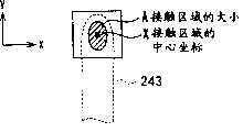
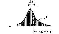
在步骤S904中,输入设备20假设移位长度L的分布,并计算移位长度L的最佳分布。具体来说,输入设备20使用手指243的接触区域A和接触区域A的中心坐标X来计算手指的接触区域在x和y方向的变化,如图38和图39所示。此外,还根据移位长度L的分布计算一个或多个参数。In step S904, the
在步骤S905中,输入设备20计算键的实际中心坐标与分布的中心的偏差,即,Δx和Δy(图38,图39)。In step S905, the
在步骤S906中,输入设备20根据前述的偏差来计算视野校准量。具体来说,输入设备20调整要显示的键或键盘的任何一个或所有坐标,以及几何参数,并计算视野校准量。In step S906, the
在步骤S907中,输入设备20显示经过视野校准之后的键盘。In step S907, the
视野校准可以对于每一个键独立地执行,也可以对于所有键或键组同时执行。任何时候当每一个键命中的累积执行达到预先确定的次数时,通过重复前述的算法,可以复位相应的键的视野校准的累积间隔或累积的移位长度L。或者,根据先进先出的原则,每次敲击键时可以累积键命中的次数,并且每次敲击键时,都可以调整偏离中心的命中量的分布。Field of view calibration can be performed independently for each key, or simultaneously for all keys or groups of keys. Whenever the cumulative execution of each key hit reaches a predetermined number of times, by repeating the aforementioned algorithm, the corresponding key's field of view calibration cumulative interval or cumulative shift length L can be reset. Alternatively, the number of key hits can be accumulated each time a key is struck, and the distribution of off-center hits can be adjusted each time a key is struck, on a first-in, first-out basis.
可以对显示单元5和触板10中的一个或两个进行视野校准。Field of view calibration may be performed on one or both of the
下面描述了根据移位长度矢量数据进行的自动键盘对齐与视野校准之间的差别。The difference between automatic keyboard alignment and field of view calibration based on shift length vector data is described below.
当甚至在自动键盘对齐之后仍观察到移位长度矢量数据时,它们常常不是由用户的不准确的击键操作而是显示单元5和触板10的视角度之间的差别所引起的。When shifted length vector data are observed even after automatic keyboard alignment, they are often not caused by inaccurate keystrokes by the user but by a difference between the viewing angles of the
图40显示了用于判断在自动键盘对齐之后是否应该进行视野校准的算法。Figure 40 shows the algorithm used to determine whether field of view calibration should be performed after automatic keyboard alignment.
步骤S1001到S1005中的过程与图34所示的步骤S901到S905中的过程相同,这里将不再赘述。The process in steps S1001 to S1005 is the same as the process in steps S901 to S905 shown in FIG. 34 , and will not be repeated here.
在步骤S1006中,输入设备20计算通过自动键盘对齐来校正键盘图像的量。在步骤S1007中,输入设备20校正键盘图像,并在步骤S1007中显示校正的图像。In step S1006, the
在步骤S1008中,输入设备20检查是否满足了视野校准要求。视野校准要求表示各种条件,即,将键盘对齐进行预先确定的次数,或者,在特定方向反复地校正键盘图像的部分或整个区域。当满足了前述的要求时,输入信息处理器20转到步骤S1009。In step S1008, the
步骤S1009和S1010中的过程与图34所示的步骤S906和S907的过程相同,这里将不再赘述。The processes in steps S1009 and S1010 are the same as the processes in steps S906 and S907 shown in FIG. 34 , and will not be repeated here.
其他处理:Other processing:
除了前面的过程之外,输入设备20还执行下列过程。当接触检测单元21由触板210作为压力传感器构成时(图8A-图8C),输入设备20计算接触检测单元21上的用户的击键压力的平均值,并响应击键压力随着时间的变化而改变键接触的阈值。In addition to the foregoing processes, the
输入设备20计算最新的预先确定的时间段或计算预先确定的次数的击键压力的平均变化作为移动平均,并确定用于识别键命中的阈值。在用户长时间对输入设备进行操作之后,用户的键命中行为可能会发生变化。甚至在这样的情况下,输入设备20也可以防止阈值被降低。此外,例如,通过观察击键压力的变化所获得的信息可以用来检测用户的疲劳或机器问题,等等。The
此外,为了执行个人识别,输入设备20存储了一个或更多用户的伪数据,并将新用户的数据与伪数据在特定特征方面进行比较。假设只注册了一个新用户,并基于马哈拉诺比斯距离来计算判断索引。在这样的情况下,判断索引可能稍微不准确,因为只根据新用户的学习的马哈拉诺比斯空间来计算马哈拉诺比斯距离。Furthermore, to perform personal identification, the
马哈拉诺比斯距离基本上是根据特定用户的马哈拉诺比斯空间来进行计算的。马哈拉诺比斯距离越小,对用户进行识别就可能越可靠。有时,当在进行打字练习之后键命中特征变化时,马哈拉诺比斯距离增大。在这样的情况下,很难识别用户。此外,有时难以确定识别或不识别用户的阈值。The Mahalanobis distance is basically calculated based on the Mahalanobis space of a specific user. The smaller the Mahalanobis distance, the more reliably the user can be identified. Sometimes, the Mahalanobis distance increases when key hitting characteristics change after typing practice. In such a case, it is difficult to identify the user. Additionally, it is sometimes difficult to determine the threshold for identifying or not identifying a user.
相反,可以存储一个或更多用户的伪数据,也可以存储这样的用户的马哈拉诺比斯空间。根据上文所提及的多个马哈拉诺比斯空间来计算要识别的用户的输入行为的马哈拉诺比斯空间。当使用特定用户的数据计算出的马哈拉诺比斯距离小于使用一个以上用户数据计算出的马哈拉诺比斯距离时,可以比较可靠地识别相关用户。Instead, dummy data for one or more users may be stored, as may the Mahalanobis space of such users. The Mahalanobis space of the input behavior of the user to be recognized is calculated according to the above-mentioned plurality of Mahalanobis spaces. When the Mahalanobis distance calculated using the data of a specific user is smaller than the Mahalanobis distance calculated using the data of more than one user, relevant users can be identified more reliably.
当存储了多个伪数据而不是只存储一个用户的数据或数量有限的用户的数据并且对于这样的有限的用户学习了马哈拉诺比斯空间时,可以可靠地执行用户识别。此外,通过预先确定特定的键或特定手指,也可以执行用户识别。例如,键F(对应于左手食指)或键J(对应于右手食指)可以用于此目的。更进一步,如果如上所述键盘逐渐地移动,则可以提供将键盘返回到在购买时设置的原始位置,或返回到对于用户来说最佳的位置的功能。When a plurality of dummy data is stored instead of only one user's data or a limited number of users' data and the Mahalanobis space is learned for such limited users, user identification can be performed reliably. In addition, user identification can also be performed by predetermining a specific key or a specific finger. For example, the key F (corresponding to the index finger of the left hand) or the key J (corresponding to the index finger of the right hand) can be used for this purpose. Still further, if the keyboard is gradually moved as described above, it is possible to provide a function of returning the keyboard to the original position set at the time of purchase, or to a position optimal for the user.
通过使用输入设备20、计算机1、信息处理方法和程序,接触检测单元21和设备控制IC 23,可以根据接触强度检测用户的手指只不过是放在触板10上还是用户敲击触板10以便输入某些数据。By using the
可以根据接触区域的大小或接触压力来检测接触强度。根据本发明,与使用相关技术的压力传感器型触板时只依赖击键压力来检测接触状态的情况相比,可以准确地检测接触状态。The contact intensity can be detected based on the size of the contact area or the contact pressure. According to the present invention, it is possible to accurately detect the contact state as compared with the case of detecting the contact state relying only on the keystroke pressure when using the pressure sensor type touch panel of the related art.
在相关技术的红外线型或图像传感器型触板中,只检测接触区域的大小和形状。因此,很难识别对象只不过是放在键上还是与键进行接触以便输入信息。本发明的输入设备20可以准确并轻松地识别键盘上的对象的接触状态。In the related art infrared type or image sensor type touch panel, only the size and shape of the touched area are detected. Therefore, it is difficult to recognize whether the object is merely placed on the key or is brought into contact with the key in order to input information. The
当根据接触压力来检测接触强度时,可以通过评估与时间有关的压力变化的速率,来准确地检测诸如输入笔之类的相对比较硬和细的,并且其接触区域易于保持不变的对象的接触状态。When detecting contact strength based on contact pressure, it is possible to accurately detect objects such as stylus pens, which are relatively hard and thin, and whose contact area tends to remain constant, by evaluating the rate of pressure change with respect to time contact status.
到目前为止,很难快速识别同时被命中的多个键。输入设备20可以准确地识别哪一个手指敲击了键以及哪些手指只不过是放在键上。因此,如果熟练的用户非常快地敲击了键并且有时以重叠的方式敲击了多个键,可以准确地识别接触状态。Until now, it was difficult to quickly identify multiple keys being hit at the same time. The
设备控制IC 23将涉及接触强度的特征量或使用特征量计算出的值与预先确定的阈值进行比较,并识别对象的接触状态。根据用户的击键习惯调整阈值,这使得同一台机器可以供多个用户使用。对于相应的用户,可以准确地识别接触状态。此外,如果击键强度随着用户熟悉机器而变化,如果用户调整他的或她的击键,则可以维持最佳使用环境。更进一步,对于相应的登录用户可以存储阈值,这些阈值可以用作默认值。The device control IC 23 compares the feature amount related to the contact intensity or a value calculated using the feature amount with a predetermined threshold, and recognizes the contact state of the object. The threshold is adjusted according to the user's keystroke habits, which allows the same machine to be used by multiple users. For the corresponding user, the contact state can be accurately identified. Furthermore, if the keystroke strength varies as the user becomes familiar with the machine, an optimal use environment can be maintained if the user adjusts his or her keystrokes. Furthermore, thresholds can be stored for corresponding logged-in users, and these thresholds can be used as default values.
显示驱动器22和显示单元5可以响应键的接触状态更改输入设备的图像的模式。请参阅图4。例如,当指示键盘为输入设备时,用户可以轻松地知道“无接触”、“接触”和“键命中”状态。这对于帮助用户熟悉机器非常有效。以不同模式显示被接触的键对于让用户知道他的或她的手指是否位于初始位置非常有效。The
如果键的亮度随着它们的接触状态而变化,用户可以在昏暗的位置使用输入设备20。此外,机器操作的彩色指示将提供下列效果:用户使用机器感觉愉快和满意,享受热爱者的感觉,拥有该机器感到开心,等等。If the brightness of the keys changes according to their contact state, the user can use the
扬声器驱动器25和扬声器26基于对象的接触位置和输入设备上的图像的位置之间的关系,并根据接触状态,产生预先确定的识别声音。用户可以知道错误键入的次数和偏离中心的量,以便用户可以练习打字。这对于使用户熟悉机器非常有效。The speaker driver 25 and the speaker 26 generate a predetermined recognition sound based on the relationship between the contact position of the object and the position of the image on the input device, and according to the contact state. The user can know the number of mistypes and the amount of off-center so that the user can practice typing. This is very effective for familiarizing the user with the machine.
设备控制IC 23可以将接触状态通知给响应来自输入设备的输出信号进行操作的设备。例如,在识别用户的手指被放置在初始位置的情况下,设备控制IC 23将此状态通知到与此连接的终端设备。The device control IC 23 can notify a contact state to a device operating in response to an output signal from an input device. For example, in the case of recognizing that the user's finger is placed at the initial position, the device control IC 23 notifies this state to the terminal device connected thereto.
发光设备27根据接触状态来发光。例如,在查看显示面板之后,用户可以知道他的或她的手指位于初始位置。The
输入设备20的自动对准根据偏离中心矢量数据来启用键盘的大小或形状。Automatic alignment of the
输入设备20的打字练习功能可使用户知道用户不擅长敲击哪些键,并在初期集中练习敲击那些键。与现有的打字练习软件相比,本发明的打字练习功能在以下方面非常突出。不仅键的中心和敲击键的手指的中心坐标之间的偏差,而且方向两者都可以被识别是连续量的矢量数据,以便可以精确地诊断键命中率。可以向用户提供调整原则,并能有效地产生要练习的连续字符串。The typing practice function of the
输入设备20的重新键入调整在下列方面是有效的。这里假设,用户首先敲击“R”键,并在输入设备20识别“R”键之后敲击删除键,以取消“R”键,用户敲击“R”键左边的“E”键。在此状态下,输入设备20存储用户的重新键入历史。如果常常观察到这种类型的错误键入,“E”键附近的各键可以向右移动,以便减少错误键入。The rekeying adjustment of the
以预先确定的间隔执行键位置调整(微调),以便可以防止输入设备20太频繁地进行调整,或防止虚拟键盘5a被太过度地校正。否则,虚拟键盘5a可能被过度地移动而难以使用。Key position adjustment (fine adjustment) is performed at predetermined intervals, so that the
当图像传感器或触摸垫检测到用户将他的或她的拳头放在输入设备上时,会识别用户将使用鼠标而不是敲击键。在此状态下,判断拳头的参考位置为右手的中心,并根据手掌和折叠的手指的位置来计算参考角。根据前述的数据计算虚拟鼠标5b的位置和角度,并在显示单元上显示虚拟鼠标5b。虚拟鼠标5b包括左右按钮,以及滚动轮,并类似于通常的滑轮鼠标工作。用户可以使用虚拟鼠标5b来对微电脑进行操作。When the image sensor or touch pad detects that the user places his or her fist on the input device, it recognizes that the user is going to use the mouse instead of hitting keys. In this state, the reference position of the fist is judged to be the center of the right hand, and the reference angle is calculated from the positions of the palm and folded fingers. The position and angle of the
虽然是通过参考特定实施例来对本发明进行描述的,但是,可以理解,本实施例只是对本发明的原理的应用的说明,不应该以限制的方式来解释。可以作出许多其他修改,在不偏离本发明的精神和范围的情况下,可以设计其他布局。While the invention has been described with reference to specific embodiments, it is to be understood that the embodiments are merely illustrative of the application of the principles of the invention and should not be construed in a limiting manner. Many other modifications may be made and other arrangements may be devised without departing from the spirit and scope of the invention.
在前面的实施例中,输入单元3与计算机30是一个整体。或者,输入单元3也可以与计算机30分离,并可以使用通用串行总线等等来与之连接。In the foregoing embodiments, the
图41显示了这样的示例:外部输入设备20连接到微电脑主单元,在显示单元(LCD)5上显示了输入设备(例如,虚拟键盘5a和虚拟鼠标5b)的图像。USB电缆7用来将输入设备20连接到微电脑主单元。关于在键盘上命中的键的信息从输入设备20被传输到微电脑主单元。在连接到计算机主单元130的显示单元上显示被处理的数据。FIG. 41 shows an example in which an
图41的输入设备20对信息进行处理,并在显示单元5上显示虚拟键盘5a(如图18到图21所示)作为输入设备3,虚拟鼠标5b,等等,类似于图1的输入设备20。在微电脑主单元130的控制下,可以执行各种操作。The
请参看图42,微电脑主单元130连接到外部输入单元140。输入设备141通过显示驱动器22从(微电脑主单元130的)图形电路35接收虚拟键盘等等的数字图像信号。显示驱动器22使显示单元5显示虚拟键盘5a等等的图像。Referring to FIG. 42 , the microcomputer
键命中/接触位置检测单元142检测触板10的接触检测表面10a上的对象的接触位置和接触状态,如参考图18到图21所描述的。虚拟键盘或鼠标的检测到的操作结果通过键盘连接电缆(PS/2电缆)或鼠标连接电缆(PS/2电缆)被传输到计算机主单元130的键盘/鼠标端口46。The key hit/contact
微电脑主单元130对虚拟键盘或鼠标的接收到的操作结果进行处理,将操作结果临时存储在诸如硬盘驱动器41之类的存储器中,并根据存储的信息执行各种过程。这些过程是图18到图21所示的基本信息输入过程;图24和图25所示的自动调整;图26所示的打字练习过程;图28所示的重新键入之后的调整;图29所示的鼠标操作;以及图31所示的视野校准。计算机主单元130使图形电路35将代表操作结果的数字图像信号发送到显示单元150的显示驱动器28。显示单元29响应数字图像信号来显示图像。此外,微电脑主单元130从图形电路35将数字图像信号发送到显示驱动器22。因此,显示单元5上的指示的颜色等等(如图16和图17所示)将改变。The microcomputer
在前面的情况下,计算机主单元130用作为显示控制器、接触强度检测器和确定单元。In the former case, the computer
或者,虚拟键盘和鼠标的操作结果可以通过USB电缆7a和7b而不是键盘连接电缆和鼠标连接电缆发送到微电脑主单元130的USB设备38,如图42中的虚线所示。Alternatively, the operation results of the virtual keyboard and mouse may be sent to the
图43显示了微电脑主单元130的外部输入单元140的另一个示例。在外部输入单元140中,触板控制/处理单元143检测触板10上的命中的键,并将检测到的结果通过串联电缆9发送到微电脑主单元130的串行/并行端口45。FIG. 43 shows another example of the
微电脑主单元130使用触板驱动器将触板识别为输入单元140,并执行必要的处理。在此情况下,计算机主单元130使用通过串行/并行端口45接收到的并临时存储在诸如硬盘驱动器41之类的存储器中的在触板上扫描的结果。该过程是图18到图21所示的基本信息输入过程;图24和图25所示的自动调整;图26所示的打字练习过程;图28所示的重新键入之后的调整;图29所示的鼠标操作;以及图31所示的视野校准。因此,计算机主单元130假设输入设备141是触板,并进行必要的处理。The microcomputer
在前述的情况下,计算机主单元130用作为显示控制器、接触强度检测器和确定单元。In the foregoing case, the computer
在图43所示的示例中,可以通过USB连接电缆7而不是串联电缆9将触板的工作状态发送到USB设备38。In the example shown in FIG. 43 , the working status of the touch panel can be sent to the
在前面的实施例中,在输入单元3中只提供了触板10。或者,可以在显示单元中提供额外的触板10。In the foregoing embodiments, only the
请参看图44,在上外壳2B中可以安装额外的触板10。可以将上外壳2B的触板10的检测到的结果传输到触板控制/处理单元143,该处理单元143通过串行连接电缆9将检测到的结果传输到串行/并行端口45。Referring to Fig. 44, an
微电脑主单元130使用触板驱动器来识别上外壳2B的触板,并进行必要的处理。The microcomputer
此外,微电脑主单元130通过图形电路35将数字图像信号发送到上外壳2B的显示驱动器28。然后,上外壳2B的显示单元29显示各种图像。上外壳2B通过图1所示的铰链19使用信号线连接到微电脑主单元130。In addition, the microcomputer
下外壳2A包括键命中/接触位置检测单元142,该单元检测对象在触板10的检测层10b上的接触位置和状态,如图18到图21所示,并通过键盘连接电缆或鼠标连接电缆(PS/2电缆)将键盘或鼠标的检测到的状态提供到键盘/鼠标端口46。The
微电脑主单元130通过图形电路35根据键盘或鼠标的操作状态,给(输入单元140的)显示驱动器22提供数字图像信号。图16和图17所示的显示单元5的指示模式将在颜色等等方面变化。The microcomputer
在前面的情况下,计算机主单元130用作为显示控制器、接触强度检测器和确定单元。In the former case, the computer
键盘或鼠标的操作结果可以通过串行连接电缆9a而不是键盘或鼠标连接电缆传输到串行/并行端口45,如图44中的虚线所示。The operation result of the keyboard or mouse may be transmitted to the serial/
在下外壳2A中,键命中/接触位置检测单元142可以替换为如图44所示的触板控制/处理单元143。微电脑主单元130可以使用触板驱动器来识别键盘或鼠标的操作结果,并进行必要的处理。In the
在本实施例中使用了电阻薄膜型触板10。或者,也可以使用光学触板,如图45所示。例如,也可以使用红外线扫描仪型传感器阵列。在红外线扫描仪型传感器阵列中,光从发光x轴阵列151e扫描到光接收x轴阵列151c,并从发光y轴阵列151d扫描到光接收y轴阵列151b。其中光路以矩阵的形状相交的空间是接触检测区域,而不是触板10。当用户试图按压显示单元5的显示层时,用户的手指首先横穿接触检测区域,并在光路151f内中断。无论是光接收x轴传感器阵列151c还是光接收y轴传感器阵列151都不会接收任何光。因此,接触检测单元21(如图4所示)可以根据X和Y坐标来检测对象的位置。接触检测单元21检测遍历接触检测区域的对象的强度(即,对象和显示单元5接触的强度)和取决于该强度的特征量。因此,将识别接触状态。例如,当具有某一截面积的手指通过接触检测区域时,红外线被手指阻挡。取决于手指通过接触检测区域的速度,单位时间被阻挡的红外线的量增大。如果手指强有力地按压,则手指在接触检测区域上快速移动。因此,可以根据被阻挡的红外线的量来检测手指是否强有力地按压。In this embodiment, a resistive film
在前面的实施例中,使用便携式微电脑作为终端设备来示范。或者,终端设备可以是电子数据图书、个人数字助理(PDA)、蜂窝电话,等等。In the foregoing embodiments, a portable microcomputer was used as a terminal device for demonstration. Alternatively, the terminal device may be an electronic data book, a personal digital assistant (PDA), a cellular phone, or the like.
在图18的流程图中,首先检测接触位置(步骤S104),然后,检测接触强度(步骤S105)。步骤S104和S105可以按逆序来执行。步骤S108(通知键命中)、步骤S109(指示键命中)和步骤S110(产生识别声音)可以按逆序来执行。前述的内容也适用于图20所示的过程。In the flowchart of FIG. 18, the contact position is first detected (step S104), and then the contact intensity is detected (step S105). Steps S104 and S105 can be performed in reverse order. Step S108 (notification of key hit), step S109 (indication of key hit), and step S110 (generating recognition sound) may be performed in reverse order. The foregoing also applies to the process shown in FIG. 20 .
Claims (11)
Translated fromChineseApplications Claiming Priority (2)
| Application Number | Priority Date | Filing Date | Title |
|---|---|---|---|
| JP2004285453 | 2004-09-29 | ||
| JP2004285453 | 2004-09-29 |
Publications (2)
| Publication Number | Publication Date |
|---|---|
| CN1755603A CN1755603A (en) | 2006-04-05 |
| CN100399253Ctrue CN100399253C (en) | 2008-07-02 |
Family
ID=36098475
Family Applications (1)
| Application Number | Title | Priority Date | Filing Date |
|---|---|---|---|
| CNB2005101076051AExpired - Fee RelatedCN100399253C (en) | 2004-09-29 | 2005-09-29 | Input device, microcomputer and information processing method |
Country Status (2)
| Country | Link |
|---|---|
| US (1) | US20060066590A1 (en) |
| CN (1) | CN100399253C (en) |
Families Citing this family (72)
| Publication number | Priority date | Publication date | Assignee | Title |
|---|---|---|---|---|
| US8479122B2 (en) | 2004-07-30 | 2013-07-02 | Apple Inc. | Gestures for touch sensitive input devices |
| US9239673B2 (en) | 1998-01-26 | 2016-01-19 | Apple Inc. | Gesturing with a multipoint sensing device |
| US7614008B2 (en) | 2004-07-30 | 2009-11-03 | Apple Inc. | Operation of a computer with touch screen interface |
| US20060033724A1 (en)* | 2004-07-30 | 2006-02-16 | Apple Computer, Inc. | Virtual input device placement on a touch screen user interface |
| US9292111B2 (en) | 1998-01-26 | 2016-03-22 | Apple Inc. | Gesturing with a multipoint sensing device |
| FI111998B (en)* | 1999-12-08 | 2003-10-15 | Nokia Corp | User interface |
| US8381135B2 (en) | 2004-07-30 | 2013-02-19 | Apple Inc. | Proximity detector in handheld device |
| US10452207B2 (en)* | 2005-05-18 | 2019-10-22 | Power2B, Inc. | Displays and information input devices |
| US8610675B2 (en) | 2007-03-14 | 2013-12-17 | Power2B, Inc. | Interactive devices |
| US20080098331A1 (en)* | 2005-09-16 | 2008-04-24 | Gregory Novick | Portable Multifunction Device with Soft Keyboards |
| US20070152980A1 (en)* | 2006-01-05 | 2007-07-05 | Kenneth Kocienda | Touch Screen Keyboards for Portable Electronic Devices |
| KR100619584B1 (en)* | 2006-01-19 | 2006-09-01 | 주식회사 넥시오 | Detailed coordinate measurement method and error correction method of touch panel |
| US7786977B2 (en)* | 2006-01-30 | 2010-08-31 | Wacom Co., Ltd. | Position input device, remote control device, computer system and electronic equipment |
| WO2007107618A1 (en)* | 2006-03-23 | 2007-09-27 | Nokia Corporation | Touch screen |
| US20070236474A1 (en)* | 2006-04-10 | 2007-10-11 | Immersion Corporation | Touch Panel with a Haptically Generated Reference Key |
| JP4729433B2 (en)* | 2006-05-10 | 2011-07-20 | アルプス電気株式会社 | Input device |
| US8564544B2 (en) | 2006-09-06 | 2013-10-22 | Apple Inc. | Touch screen device, method, and graphical user interface for customizing display of content category icons |
| KR100782431B1 (en)* | 2006-09-29 | 2007-12-05 | 주식회사 넥시오 | Multipoint Coordinate Recognition Method and Contact Area Recognition Method of Infrared Touch Screen |
| US20080136782A1 (en)* | 2006-12-11 | 2008-06-12 | Kevin Mundt | System and Method for Powering Information Handling System Keyboard Illumination |
| US8074172B2 (en) | 2007-01-05 | 2011-12-06 | Apple Inc. | Method, system, and graphical user interface for providing word recommendations |
| TWI375198B (en)* | 2007-05-17 | 2012-10-21 | Tpo Displays Corp | A system for displaying images |
| CN101315762B (en)* | 2007-05-28 | 2012-04-25 | 奇美电子股份有限公司 | Image display system |
| US20080297893A1 (en)* | 2007-05-30 | 2008-12-04 | National Taiwan University | Pressure sensitive positioning projection screen |
| KR101472585B1 (en)* | 2007-08-23 | 2014-12-15 | 삼성전자주식회사 | Function key input device and method |
| US10203873B2 (en) | 2007-09-19 | 2019-02-12 | Apple Inc. | Systems and methods for adaptively presenting a keyboard on a touch-sensitive display |
| US10126942B2 (en)* | 2007-09-19 | 2018-11-13 | Apple Inc. | Systems and methods for detecting a press on a touch-sensitive surface |
| US8560239B2 (en)* | 2007-12-12 | 2013-10-15 | The Boeing Company | System and method for multiple delete entry on control display unit |
| TWM344544U (en)* | 2007-12-25 | 2008-11-11 | Cando Corp | Sensory structure of touch panel |
| US8232973B2 (en) | 2008-01-09 | 2012-07-31 | Apple Inc. | Method, device, and graphical user interface providing word recommendations for text input |
| CN101526836A (en)* | 2008-03-03 | 2009-09-09 | 鸿富锦精密工业(深圳)有限公司 | Double-screen notebook |
| US8358277B2 (en)* | 2008-03-18 | 2013-01-22 | Microsoft Corporation | Virtual keyboard based activation and dismissal |
| JP2010015535A (en)* | 2008-06-02 | 2010-01-21 | Sony Corp | Input device, control system, handheld device, and calibration method |
| US8570279B2 (en) | 2008-06-27 | 2013-10-29 | Apple Inc. | Touch screen device, method, and graphical user interface for inserting a character from an alternate keyboard |
| US8754855B2 (en)* | 2008-06-27 | 2014-06-17 | Microsoft Corporation | Virtual touchpad |
| JP4766094B2 (en)* | 2008-10-01 | 2011-09-07 | ソニー株式会社 | Display panel, display device |
| KR101001295B1 (en)* | 2008-10-27 | 2010-12-14 | 한국전자통신연구원 | Method and device for detecting meal behavior using pressure sensor |
| US8386167B2 (en)* | 2008-11-14 | 2013-02-26 | The Boeing Company | Display of taxi route control point information |
| US9116569B2 (en)* | 2008-11-26 | 2015-08-25 | Blackberry Limited | Touch-sensitive display method and apparatus |
| TWI416400B (en)* | 2008-12-31 | 2013-11-21 | Htc Corp | Method, system, and computer program product for automatic learning of software keyboard input characteristics |
| JP5173870B2 (en)* | 2009-01-28 | 2013-04-03 | 京セラ株式会社 | Input device |
| JP4723656B2 (en) | 2009-02-03 | 2011-07-13 | 京セラ株式会社 | Input device |
| US8583421B2 (en)* | 2009-03-06 | 2013-11-12 | Motorola Mobility Llc | Method and apparatus for psychomotor and psycholinguistic prediction on touch based device |
| JP2010218066A (en)* | 2009-03-13 | 2010-09-30 | Seiko Epson Corp | Display device with touch sensor function, method for manufacturing display device with touch sensor function, and electronic apparatus |
| TW201044232A (en)* | 2009-06-05 | 2010-12-16 | Htc Corp | Method, system and computer program product for correcting software keyboard input |
| CN102447836A (en) | 2009-06-16 | 2012-05-09 | 英特尔公司 | Camera applications in a handheld device |
| US20110001641A1 (en)* | 2009-07-01 | 2011-01-06 | Mitac Technology Corporation | Electronic Device Equipped with Programmable Key Layout and Method for Programming Key Layout |
| TWI484380B (en)* | 2009-07-31 | 2015-05-11 | Mstar Semiconductor Inc | Determinative method and device of touch point movement |
| JP5482023B2 (en)* | 2009-08-27 | 2014-04-23 | ソニー株式会社 | Information processing apparatus, information processing method, and program |
| JP4947668B2 (en)* | 2009-11-20 | 2012-06-06 | シャープ株式会社 | Electronic device, display control method, and program |
| KR101657963B1 (en)* | 2009-12-08 | 2016-10-04 | 삼성전자 주식회사 | Operation Method of Device based on a alteration ratio of touch area And Apparatus using the same |
| US8806362B2 (en)* | 2010-01-06 | 2014-08-12 | Apple Inc. | Device, method, and graphical user interface for accessing alternate keys |
| JP2011192179A (en) | 2010-03-16 | 2011-09-29 | Kyocera Corp | Device, method and program for inputting character |
| GB2481606B (en)* | 2010-06-29 | 2017-02-01 | Promethean Ltd | Fine object positioning |
| KR101701932B1 (en)* | 2010-07-22 | 2017-02-13 | 삼성전자 주식회사 | Input device and control method of thereof |
| US20120098751A1 (en)* | 2010-10-23 | 2012-04-26 | Sunrex Technology Corp. | Illuminated computer input device |
| EP2646894A2 (en)* | 2010-11-30 | 2013-10-09 | Cleankeys Inc. | Dynamically located onscreen keyboard |
| KR101816721B1 (en)* | 2011-01-18 | 2018-01-10 | 삼성전자주식회사 | Sensing Module, GUI Controlling Apparatus and Method thereof |
| US9636582B2 (en)* | 2011-04-18 | 2017-05-02 | Microsoft Technology Licensing, Llc | Text entry by training touch models |
| EP2535791A3 (en)* | 2011-06-17 | 2015-10-07 | Creator Technology B.V. | Electronic device with a touch sensitive panel, method for operating the electronic device, and display system |
| US9417754B2 (en) | 2011-08-05 | 2016-08-16 | P4tents1, LLC | User interface system, method, and computer program product |
| US9507454B1 (en)* | 2011-09-19 | 2016-11-29 | Parade Technologies, Ltd. | Enhanced linearity of gestures on a touch-sensitive surface |
| TWI502403B (en) | 2011-12-27 | 2015-10-01 | Ind Tech Res Inst | Flexible display and controlling method therefor |
| CN103186329B (en)* | 2011-12-27 | 2017-08-18 | 富泰华工业(深圳)有限公司 | Electronic device and touch input control method thereof |
| JP5910345B2 (en)* | 2012-06-21 | 2016-04-27 | 富士通株式会社 | Character input program, information processing apparatus, and character input method |
| JP2014235612A (en) | 2013-06-03 | 2014-12-15 | 富士通株式会社 | Terminal device, correction method, and correction program |
| US10289302B1 (en) | 2013-09-09 | 2019-05-14 | Apple Inc. | Virtual keyboard animation |
| KR101613773B1 (en) | 2013-11-04 | 2016-04-19 | 주식회사 동부하이텍 | Touch Panel and Method Manufacturing the Same |
| US9207794B2 (en)* | 2013-12-30 | 2015-12-08 | Google Inc. | Disambiguation of user intent on a touchscreen keyboard |
| CN105468209A (en)* | 2014-09-25 | 2016-04-06 | 硕擎科技股份有限公司 | Virtual two-dimensional positioning module of input device and virtual input device |
| US20180204227A1 (en)* | 2015-09-21 | 2018-07-19 | Asheesh Mohindru | Golf Pace of Play |
| CN105511683B (en)* | 2015-12-31 | 2019-03-12 | 厦门天马微电子有限公司 | A kind of touch control display apparatus |
| CN110515510B (en)* | 2019-08-20 | 2021-03-02 | 北京小米移动软件有限公司 | Data processing method, apparatus, equipment and storage medium |
Citations (5)
| Publication number | Priority date | Publication date | Assignee | Title |
|---|---|---|---|---|
| CN2431635Y (en)* | 2000-08-09 | 2001-05-23 | 英业达股份有限公司 | Keyboard key inspection device |
| CN1388925A (en)* | 2000-12-15 | 2003-01-01 | 丁系统有限责任公司 | Pen type optical mouse device and method of controlling the same |
| JP2003196007A (en)* | 2001-12-25 | 2003-07-11 | Hewlett Packard Co <Hp> | Character input device |
| JP2003223265A (en)* | 2002-01-31 | 2003-08-08 | Sony Corp | Information input device, information processing device and method therefor, and program therefor |
| CN1704888A (en)* | 2004-06-03 | 2005-12-07 | 索尼株式会社 | Portable electronic device, method of controlling input operation, and program for controlling input operation |
Family Cites Families (17)
| Publication number | Priority date | Publication date | Assignee | Title |
|---|---|---|---|---|
| GB2232251A (en)* | 1989-05-08 | 1990-12-05 | Philips Electronic Associated | Touch sensor array systems |
| GB2245708A (en)* | 1990-06-29 | 1992-01-08 | Philips Electronic Associated | Touch sensor array systems |
| JP3171866B2 (en)* | 1991-03-08 | 2001-06-04 | パイオニア株式会社 | Pattern input device |
| US5287105A (en)* | 1991-08-12 | 1994-02-15 | Calcomp Inc. | Automatic tracking and scanning cursor for digitizers |
| US5942733A (en)* | 1992-06-08 | 1999-08-24 | Synaptics, Inc. | Stylus input capacitive touchpad sensor |
| US5880411A (en)* | 1992-06-08 | 1999-03-09 | Synaptics, Incorporated | Object position detector with edge motion feature and gesture recognition |
| US5488204A (en)* | 1992-06-08 | 1996-01-30 | Synaptics, Incorporated | Paintbrush stylus for capacitive touch sensor pad |
| DE69324067T2 (en)* | 1992-06-08 | 1999-07-15 | Synaptics Inc | Object position detector |
| US5543588A (en)* | 1992-06-08 | 1996-08-06 | Synaptics, Incorporated | Touch pad driven handheld computing device |
| JP3546337B2 (en)* | 1993-12-21 | 2004-07-28 | ゼロックス コーポレイション | User interface device for computing system and method of using graphic keyboard |
| JPH08307954A (en)* | 1995-05-12 | 1996-11-22 | Sony Corp | Device and method for coordinate input and information processor |
| AU727387B2 (en)* | 1996-08-28 | 2000-12-14 | Via, Inc. | Touch screen systems and methods |
| JP3817965B2 (en)* | 1999-04-21 | 2006-09-06 | 富士ゼロックス株式会社 | Detection device |
| EP1054340B1 (en)* | 1999-05-17 | 2008-05-28 | Nippon Telegraph and Telephone Corporation | Surface shape recognition apparatus and method |
| US6803906B1 (en)* | 2000-07-05 | 2004-10-12 | Smart Technologies, Inc. | Passive touch system and method of detecting user input |
| US20020122026A1 (en)* | 2001-03-01 | 2002-09-05 | Bergstrom Dean Warren | Fingerprint sensor and position controller |
| US20040183833A1 (en)* | 2003-03-19 | 2004-09-23 | Chua Yong Tong | Keyboard error reduction method and apparatus |
- 2005
- 2005-09-28USUS11/236,611patent/US20060066590A1/ennot_activeAbandoned
- 2005-09-29CNCNB2005101076051Apatent/CN100399253C/ennot_activeExpired - Fee Related
Patent Citations (5)
| Publication number | Priority date | Publication date | Assignee | Title |
|---|---|---|---|---|
| CN2431635Y (en)* | 2000-08-09 | 2001-05-23 | 英业达股份有限公司 | Keyboard key inspection device |
| CN1388925A (en)* | 2000-12-15 | 2003-01-01 | 丁系统有限责任公司 | Pen type optical mouse device and method of controlling the same |
| JP2003196007A (en)* | 2001-12-25 | 2003-07-11 | Hewlett Packard Co <Hp> | Character input device |
| JP2003223265A (en)* | 2002-01-31 | 2003-08-08 | Sony Corp | Information input device, information processing device and method therefor, and program therefor |
| CN1704888A (en)* | 2004-06-03 | 2005-12-07 | 索尼株式会社 | Portable electronic device, method of controlling input operation, and program for controlling input operation |
Also Published As
| Publication number | Publication date |
|---|---|
| US20060066590A1 (en) | 2006-03-30 |
| CN1755603A (en) | 2006-04-05 |
Similar Documents
| Publication | Publication Date | Title |
|---|---|---|
| CN100399253C (en) | Input device, microcomputer and information processing method | |
| JP2006127488A (en) | INPUT DEVICE, COMPUTER DEVICE, INFORMATION PROCESSING METHOD, AND INFORMATION PROCESSING PROGRAM | |
| CN100432909C (en) | Input device, microcomputer and information processing method | |
| US10452174B2 (en) | Selective input signal rejection and modification | |
| CN100377053C (en) | Input device, information processing method, and microcomputer | |
| US9261913B2 (en) | Image of a keyboard | |
| CN103443744B (en) | Dynamically positioned on-screen keyboard | |
| KR101119373B1 (en) | Operating method of hybrid touch panel | |
| US20090009482A1 (en) | Touch sensor pad user input device | |
| US20080297475A1 (en) | Input Device Having Multifunctional Keys | |
| US20090066659A1 (en) | Computer system with touch screen and separate display screen | |
| US20110012856A1 (en) | Methods for Operation of a Touch Input Device | |
| KR20130088752A (en) | Multidirectional button, key, and keyboard | |
| WO2011048840A1 (en) | Input motion analysis method and information processing device | |
| KR101077308B1 (en) | Pressure Sensing Module of Touch Panel and Its Operation Method | |
| TWI396123B (en) | Optical touch system and operating method thereof | |
| US20110025718A1 (en) | Information input device and information input method | |
| JP2006127486A (en) | INPUT DEVICE, COMPUTER DEVICE, INFORMATION PROCESSING METHOD, AND INFORMATION PROCESSING PROGRAM | |
| US20170170826A1 (en) | Optical sensor based mechanical keyboard input system and method | |
| CN101882029B (en) | Optical touch system and operating method thereof | |
| JP2006085687A (en) | INPUT DEVICE, COMPUTER DEVICE, INFORMATION PROCESSING METHOD, AND INFORMATION PROCESSING PROGRAM | |
| US20240241601A1 (en) | Coordinate input apparatus |
Legal Events
| Date | Code | Title | Description |
|---|---|---|---|
| C06 | Publication | ||
| PB01 | Publication | ||
| C10 | Entry into substantive examination | ||
| SE01 | Entry into force of request for substantive examination | ||
| C14 | Grant of patent or utility model | ||
| GR01 | Patent grant | ||
| C17 | Cessation of patent right | ||
| CF01 | Termination of patent right due to non-payment of annual fee | Granted publication date:20080702 Termination date:20130929 |