CN100399176C - Liquid crystal display device with a light guide plate - Google Patents
Liquid crystal display device with a light guide plateDownload PDFInfo
- Publication number
- CN100399176C CN100399176CCNB2006100746648ACN200610074664ACN100399176CCN 100399176 CCN100399176 CCN 100399176CCN B2006100746648 ACNB2006100746648 ACN B2006100746648ACN 200610074664 ACN200610074664 ACN 200610074664ACN 100399176 CCN100399176 CCN 100399176C
- Authority
- CN
- China
- Prior art keywords
- data line
- pixel electrode
- branch
- overlapping area
- electrode
- Prior art date
- Legal status (The legal status is an assumption and is not a legal conclusion. Google has not performed a legal analysis and makes no representation as to the accuracy of the status listed.)
- Expired - Fee Related
Links
- 239000004973liquid crystal related substanceSubstances0.000titleabstractdescription8
- 239000011159matrix materialSubstances0.000claimsabstract2
- 239000000758substrateSubstances0.000claims4
- 230000003071parasitic effectEffects0.000abstractdescription23
- 238000000034methodMethods0.000abstractdescription21
- 230000000694effectsEffects0.000abstractdescription7
- 238000010586diagramMethods0.000description23
- 239000010408filmSubstances0.000description8
- 229920000642polymerPolymers0.000description7
- 239000010409thin filmSubstances0.000description3
- 230000007547defectEffects0.000description1
- 238000009413insulationMethods0.000description1
- 239000012212insulatorSubstances0.000description1
- 238000004519manufacturing processMethods0.000description1
- 239000000463materialSubstances0.000description1
- 238000012986modificationMethods0.000description1
- 230000004048modificationEffects0.000description1
Images


Landscapes
- Liquid Crystal (AREA)
- Control Of Indicators Other Than Cathode Ray Tubes (AREA)
Abstract
Translated fromChinese
Description
Translated fromChinese技术领域technical field
本发明涉及一种薄膜晶体管液晶显示器元件结构与工艺,特别是涉及可以补偿像素电极与信号线之间的寄生电容的设计.The invention relates to a structure and technology of a thin film transistor liquid crystal display element, in particular to a design capable of compensating the parasitic capacitance between a pixel electrode and a signal line.
背景技术Background technique
一般而言,液晶面板容易因工艺偏差造成数据线与像素电极重叠偏移,使得像素电极与数据线过于接近,产生如图1所示的寄生电容(parasiticcapacitance between pixel and data line,Cpd、Cpd’),而过大的寄生电容将导致串扰(cross talk)现象;或由于曝光接合处产生的差异,亦容易造成重叠偏移而产生曝光接合不均(shot mura)等问题影响画质.这些都是影响像素电极开口率大小设计的主要因素之一.In general, liquid crystal panels are prone to overlap and offset between the data line and the pixel electrode due to process deviations, making the pixel electrode and the data line too close, resulting in parasitic capacitance (parasitic capacitance between pixel and data line, Cpd, Cpd') as shown in Figure 1 ), and excessive parasitic capacitance will lead to cross talk (cross talk); or due to differences in exposure joints, it is also easy to cause overlapping offsets, resulting in uneven exposure joints (shot mura) and other issues that affect image quality. These are all It is one of the main factors affecting the design of the aperture ratio of the pixel electrode.
因此,为减少寄生电容效应并达到高开口率的需求,现有技术利用不同的设计方式来加以解决,譬如用遮蔽电容(shielding Cs),和在数据线与像素电极间加一层聚合物绝缘薄膜(polymer insulator film).其中,多加一层聚合物绝缘薄膜的设计,虽可以减少寄生电容效应,并能让像素电极跨越数据线而达到高开口率,然而,影响聚合物绝缘薄膜减少寄生电容效应的参数,主要取决于所选聚合物绝缘薄膜的介电系数,以及聚合物绝缘薄膜的膜厚大小,亦即像素电极与数据线距离的大小.可是受限于聚合物绝缘薄膜材料开发,与其介电系数值和膜厚又可能受其它工艺步骤影响而改变,故仍会影响寄生电容被减少的能力.因此,像素电极与数据线重叠部分的大小差异,还是会造成Cpd与Cpd’的不平衡,而产生串扰或其它缺陷.Therefore, in order to reduce the parasitic capacitance effect and achieve a high aperture ratio, the existing technology uses different design methods to solve it, such as using shielding capacitance (shielding Cs), and adding a layer of polymer insulation between the data line and the pixel electrode. Thin film (polymer insulator film). Among them, the design of adding an additional layer of polymer insulating film can reduce the parasitic capacitance effect and allow the pixel electrode to cross the data line to achieve a high aperture ratio. However, the impact of the polymer insulating film reduces parasitic capacitance The parameters of the effect mainly depend on the dielectric coefficient of the selected polymer insulating film and the film thickness of the polymer insulating film, that is, the distance between the pixel electrode and the data line. However, it is limited by the development of polymer insulating film materials. The dielectric coefficient value and film thickness may be changed by other process steps, so it will still affect the ability to reduce the parasitic capacitance. Therefore, the difference in the size of the overlap between the pixel electrode and the data line will still cause the difference between Cpd and Cpd' Unbalanced, resulting in crosstalk or other defects.
此外,为解决寄生电容所造成的效应,目前也有利用点反转(dot inversion)或直行反转(column inversion)等方式驱动的液晶面板,以使相邻数据线同时间送出的信号正负极性相反,进而让Cpd与Cpd’相抵消.而且,若同时让像素电极跨越左右两边数据线上的面积固定,更可将ΔCpd减到最小.In addition, in order to solve the effect caused by parasitic capacitance, there are currently liquid crystal panels driven by dot inversion or column inversion, so that the signals sent by adjacent data lines at the same time are positive and negative. In contrast, Cpd and Cpd' are offset. Moreover, if the area of the pixel electrode across the left and right data lines is fixed at the same time, ΔCpd can be reduced to a minimum.
但是,虽然在光掩模的布局设计上,可以固定像素电极与数据线的重叠面积,如图2所示,图2为原始光掩模的像素电极与数据线重叠的示意图.在原始的光掩模设计中,各像素电极20与左右两侧数据线26、28重叠的面积相等.然而在实际生产工艺上,原先的设计值却可能因为黄光工艺而产生不同对位层的偏移,而发生如图3所绘示的实际面板上像素电极30与左右数据线36、38的重叠面积变异的状况,造成像素电极30与左侧数据线36的重叠面积大于像素电极30与右侧数据线38的重叠面积,导致寄生电容的不平衡.However, although the overlapping area of the pixel electrode and the data line can be fixed in the layout design of the photomask, as shown in Figure 2, Figure 2 is a schematic diagram of the overlapping of the pixel electrode and the data line of the original photomask. In the original photomask In the mask design, each
发明内容Contents of the invention
本发明提供一种可以补偿像素电极与信号线之间的寄生电容的薄膜晶体管液晶显示器元件的结构与工艺,以解决现有寄生电容所造成的效应.The invention provides a structure and process of a thin film transistor liquid crystal display element capable of compensating the parasitic capacitance between the pixel electrode and the signal line, so as to solve the effect caused by the existing parasitic capacitance.
根据本发明的权利要求,其在原像素电极两侧各增加一补偿分支电极,以补偿像素电极因工艺偏移与数据线所产生的寄生电容,使像素电极与左右两边的数据线的寄生电容平衡.因此,在使用点反转驱动或直行反转驱动(相邻数据线正负极性相反)的情形下,可以平衡Cpd与Cpd’的效应,并同时减低串扰或其它因曝光接合处产生的不均Cpd、Cpd’不平衡所造成的均Cpd、Cpd’不平衡的现象.According to the claims of the present invention, a compensation branch electrode is added on both sides of the original pixel electrode to compensate the parasitic capacitance of the pixel electrode due to the process offset and the data line, so that the parasitic capacitance of the pixel electrode and the data lines on the left and right sides is balanced. . Therefore, in the case of using dot inversion driving or straight row inversion driving (adjacent data lines have opposite polarities), the effects of Cpd and Cpd' can be balanced, and crosstalk or other problems caused by exposure joints can be reduced at the same time. Unbalanced Cpd and Cpd' caused by uneven Cpd and Cpd' imbalance.
由于本发明具有补偿像素电极的设计,故可有效解决因工艺偏差使数据线与像素电极重叠偏移,以及产生串扰或由于曝光接合处产生的不均等影响画质的问题.此外,本发明不限于直线型数据线的设计,其亦可应用于锯齿状数据线的设计,及以三角型(delta)排列像素设计的液晶显示器.Since the present invention has a design for compensating pixel electrodes, it can effectively solve the problems of overlap and offset of data lines and pixel electrodes due to process deviations, crosstalk or uneven image quality due to exposure joints. In addition, the present invention does not Limited to the design of linear data lines, it can also be applied to the design of zigzag data lines, and liquid crystal displays designed with delta-shaped pixels.
附图说明Description of drawings
图1所绘示为液晶面板寄生电容示意图.Figure 1 is a schematic diagram of the parasitic capacitance of the liquid crystal panel.
图2所绘示为现有原始光掩模的像素电极与数据线重叠的示意图.FIG. 2 is a schematic diagram of overlapping pixel electrodes and data lines of an existing original photomask.
图3所绘示为现有实际面板的像素电极与左右数据线的重叠面积变异的示意图.FIG. 3 is a schematic diagram of variation of the overlapping area of the pixel electrode and the left and right data lines of the existing actual panel.
图4所绘示为本发明像素电极与数据线布局设计的示意图.FIG. 4 is a schematic diagram of the pixel electrode and data line layout design of the present invention.
图5所绘示为本发明像素电极往左或右偏移时的补偿示意图.FIG. 5 is a schematic diagram of compensation when the pixel electrode of the present invention is shifted to the left or right.
图6所绘示为本发明像素电极与数据线布局设计的示意图.FIG. 6 is a schematic diagram of the pixel electrode and data line layout design of the present invention.
图7所绘示为本发明像素电极往左或右偏移时的补偿示意图.FIG. 7 is a schematic diagram of compensation when the pixel electrode of the present invention is shifted to the left or right.
图8所绘示为本发明像素电极与数据线布局设计的示意图.FIG. 8 is a schematic diagram of the pixel electrode and data line layout design of the present invention.
图9所绘示为本发明像素电极往左或右偏移时的补偿示意图.FIG. 9 is a schematic diagram of compensation when the pixel electrode of the present invention is shifted to the left or right.
图10所绘示为本发明像素电极与数据线布局设计的示意图.FIG. 10 is a schematic diagram of layout design of pixel electrodes and data lines in the present invention.
图11所绘示为本发明像素电极与数据线布局设计的示意图.FIG. 11 is a schematic diagram of the pixel electrode and data line layout design of the present invention.
图12所绘示为本发明像素电极往左或右偏移时的补偿示意图.FIG. 12 is a schematic diagram of compensation when the pixel electrode of the present invention is shifted to the left or right.
图13所绘示为本发明像素电极与数据线布局设计的示意图.FIG. 13 is a schematic diagram of layout design of pixel electrodes and data lines in the present invention.
图14~17所绘示为本发明应用于锯齿状数据线与像素电极布局设计的示意图.14-17 are schematic diagrams of the application of the present invention in the layout design of zigzag data lines and pixel electrodes.
图18、19所绘示为本发明应用于三角型排列像素的数据线与像素电极布局设计的示意图.18 and 19 are schematic diagrams of the present invention applied to the layout design of data lines and pixel electrodes of pixels arranged in a triangle.
简单符号说明simple notation
20、30、40、50、70、80、90、100、110、120、130、140、150:像素电极;20, 30, 40, 50, 70, 80, 90, 100, 110, 120, 130, 140, 150: pixel electrodes;
42、52、72、82、95、102、112、122、132:第一分支电极;42, 52, 72, 82, 95, 102, 112, 122, 132: first branch electrodes;
44、54、74、84、96、104、114、124、134:第二分支电极;44, 54, 74, 84, 96, 104, 114, 124, 134: second branch electrodes;
26、36、46、56、76、86、97、146、156:第一数据线;26, 36, 46, 56, 76, 86, 97, 146, 156: the first data line;
28、38、48、58、78、88、98、148、158:第二数据线;28, 38, 48, 58, 78, 88, 98, 148, 158: the second data line;
91:第一分支数据线;91: the first branch data line;
92:第二分支数据线;92: the second branch data line;
93:第三分支数据线;93: the third branch data line;
94:第四分支数据线;94: the fourth branch data line;
106、116、126、136:第一锯齿状数据线;106, 116, 126, 136: the first zigzag data line;
108、118、128、138:第二锯齿状数据线;108, 118, 128, 138: the second zigzag data line;
141、151:第一子像素电极;141, 151: first sub-pixel electrodes;
142、152:第二子像素电极;142, 152: second sub-pixel electrodes;
143、153:第三数据线;143, 153: the third data line;
具体实施方式Detailed ways
本发明利用在像素电极两侧各增加一补偿分支电极,以补偿像素电极因工艺偏移与数据线所产生的寄生电容,使像素电极与左右两边的数据线的寄生电容得以补偿平衡,其优选实施方式可概述如下:In the present invention, a compensation branch electrode is added on both sides of the pixel electrode to compensate the parasitic capacitance of the pixel electrode due to the process offset and the data line, so that the parasitic capacitance of the pixel electrode and the data lines on the left and right sides can be compensated and balanced. Implementations can be summarized as follows:
实施例一:Embodiment one:
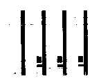
请参考图4,图4为原始光掩模的像素电极与数据线布局设计的示意图.如图4所示,像素电极40刚好切齐数据线46、48,亦即不与两侧的数据线46、48相重叠,而补偿用的第一分支电极42及第二分支电极44分别配置在像素电极40相对于数据线46、48的另一侧,且第一分支电极42及第二分支电极44与像素电极40电连接在一起。Please refer to FIG. 4. FIG. 4 is a schematic diagram of the pixel electrode and data line layout design of the original photomask. As shown in FIG. 46, 48 overlap each other, and the
请参考图5,图5为实际工艺的面板上像素电极40与左右数据线46、48的重叠面积变异的补偿示意图.如图5所示,当因黄光工艺产生对位偏移等变异,而使像素电极40往左偏移时,会同时增加像素电极40与其左侧的第一数据线46重叠的面积A(以下各图中重叠部分皆以斜线表示),以及第二分支电极44与其左侧的第二数据线48重叠的面积B,而且两者增加的面积是一样的,亦即A=B.反之,当像素电极40往右偏移时,则会同时增加第一分支电极42与其右侧的第一数据线46重叠的面积A,以及像素电极40与其右侧的第二数据线48重叠的面积B,而且两者增加的面积亦是一样的,亦即A=B.因此补偿偏移重叠的面积相同.Please refer to FIG. 5. FIG. 5 is a schematic diagram of compensation for variations in the overlapping area of the
实施例二:Embodiment two:
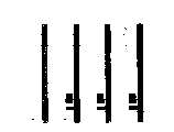
请参考图6,图6为原始光掩模的像素电极与数据线布局设计的示意图.如图6所示,像素电极50、第一分支电极52及第二分支电极54分别与数据线56、58有重叠,而且像素电极50与第一数据线56重叠的面积为A’,像素电极50与第二数据线58重叠的面积为B,第一分支电极52与第一数据线56重叠的面积为A,第二分支电极54与第二数据线58重叠的面积为B’.Please refer to FIG. 6. FIG. 6 is a schematic diagram of the pixel electrode and data line layout design of the original photomask. As shown in FIG. 58 overlaps, and the area where the
请参考图7,图7为实际工艺的面板上像素电极50与左右数据线56、58的重叠面积变异的补偿示意图.如图7所示,当因黄光工艺产生对位偏移等变异,而使像素电极50往左偏移时,会增加像素电极50与其左侧的第一数据线56重叠面积A’的大小,以及第二分支电极54与其左侧的第二数据线58重叠面积B’的大小,而且会同时减少第一分支电极52与其右侧的第一数据线56重叠面积A的大小,以及像素电极50与其右侧的第二数据线58重叠面积B的大小;反之,像素电极50往右偏移时,则会增加像素电极50与其右侧的第二数据线58重叠面积B的大小,以及第一分支电极52与其右侧的第一数据线56重叠面积A的大小,而且会同时减少第二分支电极54与其左侧的第二数据线58重叠面积B’的大小,以及像素电极50与其左侧的第一数据线56重叠面积A’的大小.Please refer to FIG. 7. FIG. 7 is a schematic diagram of compensation for variations in the overlapping area of the
然而,不论像素电极50因曝光对位工艺向左或向右偏移,在本实施例中,第一分支电极52与第一数据线56重叠的面积加上像素电极50与第一数据线56重叠的面积可以等于像素电极50与第二数据线58重叠的面积加上第二分支电极54与第二数据线58重叠的面积,亦即A+A’面积可以等于B+B’,以使ΔCpd减到最小.However, regardless of whether the
实施例三:Embodiment three:
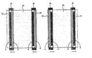
请参考图8,图8为原始光掩模的像素电极与数据线布局设计的示意图.如图8所示,像素电极70切齐第一数据线76的右侧,而与像素电极70电连接的第二分支电极74则与第二数据线78的右侧相切齐.其中,像素电极70与第二数据线78的重叠面积为C,而与像素电极70电连接的第一分支电极72与第一数据线76的重叠面积为D,且像素电极70与第二数据线78的重叠面积等于与像素电极70电连接的第一分支电极72与第一数据线76的重叠面积,即C等于D.Please refer to FIG. 8. FIG. 8 is a schematic diagram of the pixel electrode and data line layout design of the original photomask. As shown in FIG. The
请参考图9,图9为实际工艺的面板上像素电极70与左右数据线76、78的重叠面积变异的补偿示意图.如图9所示,当因黄光工艺产生对位偏移等变异,而使像素电极70往左偏移时,会使像素电极70与其左侧的第一数据线76形成一重叠面积D’,以及使第二分支电极74与其左侧的第二数据线78形成一重叠面积C’,而且会同时减少第一分支电极72与其右侧的第一数据线76重叠面积D的大小,以及减少像素电极70与其右侧的第二数据线78重叠面积C的大小,但C+C’仍等于或接近D+D’;反之,像素电极70往右偏移时,则会增加像素电极70与其右侧的第二数据线78重叠面积C的大小,以及第一分支电极72与其右侧的第一数据线76重叠面积D的大小,而且重叠面积C的增加大小会等于重叠面积D的增加大小.Please refer to FIG. 9. FIG. 9 is a schematic diagram of compensation for variations in the overlapping area of the
值得注意的是,本实施例的原始光掩模所设计的重叠的区域可同时位于第一数据线76及第二数据线78的左侧,如图8所示,或同时位于第一数据线76及第二数据线78的右侧,如图10所示.当像素电极70向左或向右偏移时,数据线76、78与各电极70、72、74于左右两侧的总重叠面积都会相同.It should be noted that the overlapping area designed by the original photomask of this embodiment can be located at the left side of the
实施例四:Embodiment four:
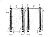
请参考图11,图11为原始光掩模的像素电极与数据线布局设计的示意图.如图11所示,像素电极80同时与第一数据线86左侧及第二数据线88右侧相切齐.其中,与像素电极80电连接的第一分支电极82与第一数据线86的重叠面积为E,与像素电极80电连接的第二分支电极84与第二数据线88的重叠面积为F,且与像素电极80电连接的第一分支电极82与第一数据线86的重叠面积等于与像素电极80电连接的第二分支电极84与第二数据线88的重叠面积,即E等于F.Please refer to FIG. 11. FIG. 11 is a schematic diagram of the pixel electrode and data line layout design of the original photomask. As shown in FIG. Qi Qi. Wherein, the overlapping area of the
同样地,如图12所示,当因黄光工艺产生对位偏移等变异,而使像素电极80向左或向右偏移时,数据线86、88与各电极80、82、84于左右两侧的总重叠面积都会相同.Similarly, as shown in FIG. 12 , when the
实施例五:Embodiment five:
本发明的补偿偏移所造成的Cpd设计,亦可以应用在数据线的部份分段,而这些分段可以由分支数据线来达到.如图13所示,第一分支数据线91及第二分支数据线92电连接而成第一数据线97,第三分支数据线93及第四分支数据线94电连接而成第二数据线98.而且像素电极90同时切齐分支数据线92及分支数据线93,第一分支电极95切齐分支数据线92,第二分支电极96切齐分支数据线93.当像素电极90向左或向右偏移时,分支数据线92、93与各电极90、92、94于左右两侧的总重叠面积都会相同.此外,其它分支数据线与像素电极及分支电极的重叠情况类似实施例一至四,在此不多加赘述.本发明补偿偏移所造成的Cpd设计不限于直线型数据线的设计,亦可应用于锯齿状(zigzag)数据线的设计,实施方式如下所述.The Cpd design caused by the compensation offset of the present invention can also be applied to some segments of the data line, and these segments can be achieved by branch data lines. As shown in Figure 13, the first branch data line 91 and the second branch data line The two branch data lines 92 are electrically connected to form the first data line 97, the third branch data line 93 and the fourth branch data line 94 are electrically connected to form the second data line 98. And the
实施例六:Embodiment six:
如图14所示,像素电极100部份切齐第一锯齿状数据线106及第二锯齿状数据线108,与像素电极100电连接的第一分支电极102切齐第一数据线106,而与像素电极100电连接的第二分支电极104切齐第二数据线108.当因黄光工艺产生对位偏移等变异,而使当像素电极100向左或向右偏移时,数据线106、108与各电极100、102、104于左右两侧的总重叠面积都会相同.实施例七:As shown in FIG. 14 , the
图15所示为锯齿状数据线的另一补偿偏移所造成的Cpd设计。像素电极110与第一锯齿状数据线116的重叠面积为G’,像素电极110与第二锯齿状数据线118的重叠面积为H,与像素电极110电连接的第一分支电极112与第一锯齿状数据线116的重叠面积为G,与像素电极110电连接的第二分支电极114与第二锯齿状数据线118的重叠面积为H’,且与像素电极110电连接的第一分支电极112与第一锯齿状数据线116的重叠面积加上像素电极110与第一锯齿状数据线116的重叠面积等于像素电极110与第二锯齿状数据线118的重叠面积加上与像素电极110电连接的第二分支电极114与第二锯齿状数据线118的重叠面积,亦即G+G’等于H+H’.当因黄光工艺产生对位偏移等变异,而使当像素电极110向左或向右偏移时,数据线116、118与各电极110、112、114于左右两侧的总重叠面积都会相同.FIG. 15 shows the Cpd design caused by another compensation offset of the sawtooth data line. The overlapping area of the
实施例八:Embodiment eight:
图16所示为锯齿状数据线的另一补偿偏移所造成的Cpd设计。像素电极120与第一锯齿状数据线126切齐,与像素电极120电连接的第二分支电极124与第二锯齿状数据线128切齐.其中,像素电极120与第二锯齿状数据线128的重叠面积为C’,与像素电极120电连接的第一分支电极122与第一锯齿状数据线126的重叠面积为D’,且像素电极120与第二锯齿状数据线128的重叠面积等于与像素电极120电连接的第一分支电极122与第一锯齿状数据线126的重叠面积,即C’等于D’.此外,本实施例所设计的重叠的区域亦可同时位于第一锯齿状数据线126及第二锯齿状数据线128的左侧,或同时位于第一锯齿状数据线126及第二锯齿状数据线128的右侧.当因黄光工艺产生对位偏移等变异,而使当像素电极120向左或向右偏移时,数据线126、128与各电极120、122、124于左右两侧的总重叠面积会相同.FIG. 16 shows the Cpd design caused by another compensation offset of the sawtooth data line. The
实施例九:Embodiment nine:
图17所示为锯齿状数据线的另一补偿偏移所造成的Cpd设计。像素电极130同时与第一锯齿状数据线136及第二锯齿状数据线138部份切齐.其中,与像素电极电连接的第一分支电极132与第一锯齿状数据线136的重叠面积为E’,与像素电极130电连接的第二分支电极134与第二锯齿状数据线138的重叠面积为F’,且与像素电极130电连接的第一分支电极132与第一锯齿状数据线136的重叠面积等于与像素电极130电连接的第二分支电极134与第二锯齿状数据线138的重叠面积,即E’等于F’.当因黄光工艺产生对位偏移等变异,而使当像素电极130向左或向右偏移时,数据线136、138与各电极130、132、134于左右两侧的总重叠面积都会相同.FIG. 17 shows the Cpd design caused by another compensation offset of the sawtooth data line. The
与上述应用于一般像素排列设计的补偿方式比较,本发明补偿偏移所造成的Cpd设计,亦可应用于以三角型排列像素的设计,而不限于一般阵列式像素排列设计的补偿方式,实施方式如下所述.Compared with the above-mentioned compensation method applied to the general pixel arrangement design, the Cpd design caused by the compensation offset of the present invention can also be applied to the design of the triangular arrangement of pixels, and is not limited to the compensation method of the general array pixel arrangement design. The way is as described below.
实施例十:Embodiment ten:
如图18所示.像素电极140由彼此电连接的第一子像素电极141及第二子像素电极142组成.其中,第一子像素电极141与第一数据线146重叠的面积为M,第一子像素电极141与第二数据线148重叠的面积为N,第二子像素电极142与第二数据线148重叠的面积为O,第二子像素电极142与第三数据线143重叠的面积为P,而且第一子像素电极141与第一数据线146重叠的面积加上第二子像素电极142与第三数据线143重叠的面积等于第一子像素电极141与第二数据线148重叠的面积加上第二子像素电极142与第二数据线148重叠的面积,即M+P等于N+O时可以使ΔCpd减到最小.当因黄光工艺产生对位偏移等变异,而使当像素电极140向左或向右偏移时,数据线146、148、143与各电极141、142于左右两侧的总重叠面积会相同.As shown in Figure 18, the
实施例十一:Embodiment eleven:
图19所示为以三角型排列像素的补偿另一种方式.像素电极150由彼此电连接的第一子像素电极151及第二子像素电极152组成.其中,第一子像素电极151与第一数据线156重叠的面积为M’,第一子像素电极151与第二数据线158重叠的面积为N’,第二子像素电极152与第二数据线158重叠的面积为O’,第二子像素电极152与第三数据线153重叠的面积为P’,而且第一子像素电极151与第二数据线158重叠的面积加上第二子像素电极152与第二数据线158重叠的面积等于像素电极150与第二数据线158重叠的面积且等于第一子像素电极151与第一数据线156重叠的面积加上第二子像素电极152与第三数据线153重叠的面积,即N’+O’等于像素电极150与第二数据线158重叠的面积且等于M’+P’时,可以使ΔCpd减到最小.当像素电极150向左或向右偏移,数据线156、158、153与各电极151、152于左右两侧的总重叠面积都会相同.Fig. 19 shows another way of compensation for pixels arranged in a triangle. The
以上所述皆为本发明利用补偿分支电极的设计,以补偿像素电极因工艺偏移与数据线所产生的寄生电容,使像素电极与左右两边的数据线的寄生电容平衡.All of the above is the design of the compensation branch electrode in the present invention to compensate the parasitic capacitance of the pixel electrode due to the process offset and the data line, so as to balance the parasitic capacitance of the pixel electrode and the data lines on the left and right sides.
以上所述仅为本发明的优选实施例,凡依本发明权利要求所做的等同变化与修饰,皆应属本发明的涵盖范围.The above are only preferred embodiments of the present invention, and all equivalent changes and modifications made according to the claims of the present invention shall fall within the scope of the present invention.
Claims (7)
Priority Applications (1)
| Application Number | Priority Date | Filing Date | Title |
|---|---|---|---|
| CNB2006100746648ACN100399176C (en) | 2006-04-21 | 2006-04-21 | Liquid crystal display device with a light guide plate |
Applications Claiming Priority (1)
| Application Number | Priority Date | Filing Date | Title |
|---|---|---|---|
| CNB2006100746648ACN100399176C (en) | 2006-04-21 | 2006-04-21 | Liquid crystal display device with a light guide plate |
Publications (2)
| Publication Number | Publication Date |
|---|---|
| CN1834761A CN1834761A (en) | 2006-09-20 |
| CN100399176Ctrue CN100399176C (en) | 2008-07-02 |
Family
ID=37002569
Family Applications (1)
| Application Number | Title | Priority Date | Filing Date |
|---|---|---|---|
| CNB2006100746648AExpired - Fee RelatedCN100399176C (en) | 2006-04-21 | 2006-04-21 | Liquid crystal display device with a light guide plate |
Country Status (1)
| Country | Link |
|---|---|
| CN (1) | CN100399176C (en) |
Cited By (1)
| Publication number | Priority date | Publication date | Assignee | Title |
|---|---|---|---|---|
| WO2011060595A1 (en)* | 2009-11-18 | 2011-05-26 | 深超光电(深圳)有限公司 | Pixel array |
Families Citing this family (9)
| Publication number | Priority date | Publication date | Assignee | Title |
|---|---|---|---|---|
| CN100573287C (en)* | 2008-07-15 | 2009-12-23 | 友达光电股份有限公司 | Liquid crystal display panel and pixel structure thereof |
| US20100060557A1 (en)* | 2008-09-10 | 2010-03-11 | Himax Technologies Limited | Data de-skew block device and method of de-skewing transmitted data |
| CN102053439A (en)* | 2010-11-24 | 2011-05-11 | 深圳市华星光电技术有限公司 | Pixel unit and liquid crystal display panel |
| TWI542932B (en)* | 2014-07-22 | 2016-07-21 | 友達光電股份有限公司 | Display panel and curved display |
| KR102160122B1 (en)* | 2014-09-10 | 2020-09-28 | 엘지디스플레이 주식회사 | Liquid crystal display |
| CN104375340B (en)* | 2014-11-14 | 2017-04-12 | 友达光电股份有限公司 | Pixel structure |
| CN111090204A (en)* | 2020-03-22 | 2020-05-01 | 深圳市华星光电半导体显示技术有限公司 | Array substrate and display panel |
| CN111308811B (en)* | 2020-04-02 | 2022-10-04 | Tcl华星光电技术有限公司 | Array substrate and display panel |
| CN111427201A (en)* | 2020-04-30 | 2020-07-17 | 京东方科技集团股份有限公司 | Array substrate and display panel |
Citations (4)
| Publication number | Priority date | Publication date | Assignee | Title |
|---|---|---|---|---|
| CN1161464A (en)* | 1995-11-20 | 1997-10-08 | 现代电子产业株式会社 | Liquid crystal display device and method of fabricating the same |
| CN1591151A (en)* | 2003-09-02 | 2005-03-09 | 夏普株式会社 | Active element substrate and liquid crystal display device using the same |
| CN1619396A (en)* | 2003-11-18 | 2005-05-25 | 三星电子株式会社 | Liquid crystal display, thin film diode panel and manufacturing method thereof |
| CN1632684A (en)* | 2005-01-31 | 2005-06-29 | 广辉电子股份有限公司 | Liquid crystal panel structure and its forming method |
- 2006
- 2006-04-21CNCNB2006100746648Apatent/CN100399176C/ennot_activeExpired - Fee Related
Patent Citations (4)
| Publication number | Priority date | Publication date | Assignee | Title |
|---|---|---|---|---|
| CN1161464A (en)* | 1995-11-20 | 1997-10-08 | 现代电子产业株式会社 | Liquid crystal display device and method of fabricating the same |
| CN1591151A (en)* | 2003-09-02 | 2005-03-09 | 夏普株式会社 | Active element substrate and liquid crystal display device using the same |
| CN1619396A (en)* | 2003-11-18 | 2005-05-25 | 三星电子株式会社 | Liquid crystal display, thin film diode panel and manufacturing method thereof |
| CN1632684A (en)* | 2005-01-31 | 2005-06-29 | 广辉电子股份有限公司 | Liquid crystal panel structure and its forming method |
Cited By (1)
| Publication number | Priority date | Publication date | Assignee | Title |
|---|---|---|---|---|
| WO2011060595A1 (en)* | 2009-11-18 | 2011-05-26 | 深超光电(深圳)有限公司 | Pixel array |
Also Published As
| Publication number | Publication date |
|---|---|
| CN1834761A (en) | 2006-09-20 |
Similar Documents
| Publication | Publication Date | Title |
|---|---|---|
| CN100399176C (en) | Liquid crystal display device with a light guide plate | |
| US7705950B2 (en) | Liquid crystal display | |
| CN103163696B (en) | Liquid crystal indicator | |
| US8054272B2 (en) | Display apparatus | |
| CN105116637B (en) | Display panel and curved surface display | |
| TWI408477B (en) | Pixel array, and polymer stablized alignment liquid crystal display panel | |
| US8248552B2 (en) | Pixel array, polymer stabilized alignment liquid crystal display panel, and electro-optical apparatus | |
| US8508704B2 (en) | Pixel array | |
| US7986377B2 (en) | LCD panel array substrates | |
| US8643802B2 (en) | Pixel array, polymer stablized alignment liquid crystal display panel, and pixel array driving method | |
| KR20010081677A (en) | method for fabricating liquid crystal display device | |
| CN101504503A (en) | Pixel array, liquid crystal display panel and photoelectric device | |
| KR101650197B1 (en) | Liquid Crystal Display Device and Manufacturing Method thereof | |
| CN104730781A (en) | ADS array substrate, manufacturing method thereof, and display device comprising same | |
| WO2017063239A1 (en) | Array substrate, liquid crystal display panel, and drive method | |
| CN104793414B (en) | LCD panel | |
| CN113724604A (en) | Display substrate and electronic equipment | |
| CN101782703B (en) | Pixel array | |
| JP5431993B2 (en) | Display device | |
| CN107918221A (en) | Display base plate and display device | |
| CN101908539A (en) | Pixel array, polymer stable alignment liquid crystal display panel and photoelectric device | |
| TWI406072B (en) | Pixel structure, active device array, display panel, and display apparatus | |
| TW201530241A (en) | Liquid crystal display panel | |
| US9117703B2 (en) | Liquid crystal display device | |
| WO2017098559A1 (en) | Terminal connection structure and display device |
Legal Events
| Date | Code | Title | Description |
|---|---|---|---|
| C06 | Publication | ||
| PB01 | Publication | ||
| C10 | Entry into substantive examination | ||
| SE01 | Entry into force of request for substantive examination | ||
| C14 | Grant of patent or utility model | ||
| GR01 | Patent grant | ||
| CF01 | Termination of patent right due to non-payment of annual fee | ||
| CF01 | Termination of patent right due to non-payment of annual fee | Granted publication date:20080702 |