CN100395637C - Light source module - Google Patents
Light source moduleDownload PDFInfo
- Publication number
- CN100395637C CN100395637CCNB2005101268901ACN200510126890ACN100395637CCN 100395637 CCN100395637 CCN 100395637CCN B2005101268901 ACNB2005101268901 ACN B2005101268901ACN 200510126890 ACN200510126890 ACN 200510126890ACN 100395637 CCN100395637 CCN 100395637C
- Authority
- CN
- China
- Prior art keywords
- light source
- source module
- units
- sides
- unit
- Prior art date
- Legal status (The legal status is an assumption and is not a legal conclusion. Google has not performed a legal analysis and makes no representation as to the accuracy of the status listed.)
- Expired - Fee Related
Links
- RYGMFSIKBFXOCR-UHFFFAOYSA-NCopperChemical compound[Cu]RYGMFSIKBFXOCR-UHFFFAOYSA-N0.000claimsdescription8
- 239000011889copper foilSubstances0.000claimsdescription7
- 238000005538encapsulationMethods0.000claims8
- 238000004806packaging method and processMethods0.000abstractdescription23
- 239000004973liquid crystal related substanceSubstances0.000abstractdescription18
- 238000009826distributionMethods0.000abstractdescription4
- 238000010586diagramMethods0.000description10
- 238000000034methodMethods0.000description5
- 238000004519manufacturing processMethods0.000description4
- 239000002184metalSubstances0.000description3
- 229910052751metalInorganic materials0.000description3
- 229910052802copperInorganic materials0.000description1
- 239000010949copperSubstances0.000description1
- 230000005923long-lasting effectEffects0.000description1
- 239000000463materialSubstances0.000description1
- 238000012986modificationMethods0.000description1
- 230000004048modificationEffects0.000description1
- 229910000679solderInorganic materials0.000description1
- 238000005476solderingMethods0.000description1
- 239000000126substanceSubstances0.000description1
Images


Landscapes
- Planar Illumination Modules (AREA)
- Liquid Crystal (AREA)
Abstract
Description
Translated fromChinese技术领域technical field
本发明是关于一种光源模块,特别是一种应用于液晶显示器的侧光源模块。The invention relates to a light source module, in particular to a side light source module applied to a liquid crystal display.
背景技术Background technique
近年来液晶显示器被广泛地应用在笔记本计算机、个人数字助理、移动电话等电子信息产品中。而液晶显示器为一种被动发光的平面显示装置,因此需要一背光模块来提供光线来源。In recent years, liquid crystal displays have been widely used in electronic information products such as notebook computers, personal digital assistants, and mobile phones. The liquid crystal display is a passive light-emitting flat display device, so a backlight module is required to provide a light source.
目前应用于背光模块中的光源主要有冷阴极荧光灯管(cold cathodefluorescence lamp,CCFL)与发光二极管(light emitting diode,LED)两种。其中,CCFL的发光效率较高,但其体积较大并且耗电,因此一般适用于彩色化、亮度需求高、且大尺寸的产品中。虽然LED的发光效率不若CCFL,但是其具有体积轻薄、光线集中、寿命持久、且废弃时污染较少等优点,因此一般需要省电、小尺寸的电子装置,均适用以LED作为其显示器背光模块的光源。At present, the light sources used in the backlight module mainly include cold cathode fluorescent lamp (cold cathode fluorescence lamp, CCFL) and light emitting diode (light emitting diode, LED). Among them, CCFL has high luminous efficiency, but its volume is large and consumes power, so it is generally applicable to products with colorization, high brightness requirements, and large size. Although the luminous efficiency of LED is not as good as that of CCFL, it has the advantages of light and thin volume, concentrated light, long-lasting life, and less pollution when discarded. Therefore, it is generally suitable for electronic devices that need power saving and small size to use LED as their display backlight. The light source for the module.
背光模块可依其光源的所在位置可更进一步区分为光源产生自显示面板正下方的直下式(direct illuminance)背光模块及光源来自显示面板侧边附近的侧光式背光模块。The backlight module can be further divided into direct illuminance backlight modules, in which the light source is generated directly below the display panel, and edge-lit backlight modules, in which the light source is generated near the side of the display panel, according to the position of the light source.
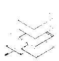
请参考图1,其为传统液晶显示装置的侧剖面结构简图。图1中的液晶显示器1包括一液晶显示面板11、及一背光模块12。其中,背光模块12包括一LED光源模块13、一导光板14、一框架15及一印刷电路板16。图1中的LED光源模块13包括两组LED灯131焊接于一软性电路板132上,软性电路板132上已有电路布局(circuit layout),用以将LED灯电性连结至印刷电路板16上的灯源驱动组件(图中未示)上。Please refer to FIG. 1 , which is a schematic side cross-sectional structure diagram of a conventional liquid crystal display device. The liquid crystal display 1 in FIG. 1 includes a liquid
上述的装置已被应用在多种电子产品上,不同的电子产品因其不同的需求而有不同的面板尺寸大小,也有不同的亮度需求。在生产流程中,每一个不同尺寸的面板,均需要不同大小的软性电路板132并配合亮度焊接不同数量的LED灯。对于生产流程来说是一项耗费时间及耗材的步骤。因此,如何发展出一方便配置的侧光源模块,可调整适用作为各种不同尺寸的面板的背光源,一直是相关业者努力的方向之一。The above-mentioned device has been applied to various electronic products, and different electronic products have different panel sizes and brightness requirements due to different requirements. In the production process, each panel of different size requires
发明内容Contents of the invention
本发明的目的为提供一种光源模块,以应用于液晶显示器作为其背光模块。The object of the present invention is to provide a light source module, which can be used as a backlight module of a liquid crystal display.
本发明的另一主要目的为提供一光源模块,以应用于不同面板尺寸的液晶显示器中。Another main purpose of the present invention is to provide a light source module for use in liquid crystal displays with different panel sizes.
本发明的另一主要目的为提供一应用于液晶显示器中的光源模块,可调整其内部的光源亮度配置以配合不同面板的需求。Another main purpose of the present invention is to provide a light source module used in a liquid crystal display, which can adjust the brightness configuration of the light source inside to meet the requirements of different panels.
本发明公开一种光源模块,包括多个LED封装单元及多个连接单元。上述的LED封装单元均在两侧分别具有一连接部。而上述的连接单元亦均在两侧分别具有一连接部,所述连接单元与所述LED封装单元借由上述连接部而相互串接。其中,借由改变连接单元及LED封装单元的组合排列成及数量以应用于不同尺寸或不同亮度分布的液晶显示屏幕的侧光源模块。The invention discloses a light source module, which comprises a plurality of LED package units and a plurality of connection units. The above-mentioned LED packaging units each have a connection portion on both sides. The above connection units also have a connection portion on both sides respectively, and the connection unit and the LED package unit are connected in series through the above connection portion. Among them, by changing the combination arrangement and quantity of the connection unit and the LED packaging unit, it can be applied to the side light source module of the liquid crystal display screen with different sizes or different brightness distributions.
在优选实施例中,上述的连接部可分别为一公插头及一母插座形式。而所述连接部间借由配置铜箔线路或电性接点以达电性连结。In a preferred embodiment, the above-mentioned connecting parts can be in the form of a male plug and a female socket respectively. The connecting parts are electrically connected by disposing copper foil lines or electrical contacts.
附图说明Description of drawings
借由以下详细的描述结合附图,将可轻易明了上述内容及此项发明的诸多优点,其中:With the help of the following detailed description combined with the accompanying drawings, the above contents and many advantages of this invention can be easily understood, wherein:
图1为传统LCD显示装置的侧剖面结构简图。FIG. 1 is a schematic side sectional structure diagram of a conventional LCD display device.
图2A~图2B为本发明所公开的连接单元及LED封装单元连接方式示意图。FIGS. 2A-2B are schematic diagrams of connection methods of the connection unit and the LED packaging unit disclosed in the present invention.
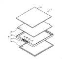
图3为本发明所公开的光源模块应用于液晶显示器的一优选实施例结构示意简图。FIG. 3 is a schematic structural diagram of a preferred embodiment in which the light source module disclosed in the present invention is applied to a liquid crystal display.
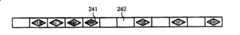
图4A~图4C为本发明所公开的连接单元及LED封装单元不同排列组合型式的图标。4A to 4C are icons of different arrangements and combinations of the connection unit and the LED packaging unit disclosed in the present invention.
主要组件符号说明Explanation of main component symbols
1 液晶显示器1 LCD display
11 液晶显示面板11 LCD display panel
12 背光模块12 backlight module
13 LED光源模块13 LED light source module
131 LED灯131 LED lights
132 软性电路板132 flexible circuit board
14 导光板14 Light guide plate
15 框架15 frames
16 印刷电路板16 printed circuit board
2 液晶显示器2 LCD display
21 显示面板21 display panel
22 背光模块22 backlight module
23 导光板23 light guide plate
24 侧光源模块24 side light module
25 框架25 frames
26 印刷电路板26 printed circuit boards
241 LED封装单元241 LED packaging unit
242 连接单元242 connection unit
241a~241b连接部241a~241b connection part
242a~242b连接部242a~242b connection part
AA 铜箔线路AA copper foil line
BB 电性接点BB electrical contacts
具体实施方式Detailed ways
本发明所公开为一种液晶显示器的光源模块,以具有一可调整式的光源设计来适应不同面板尺寸的液晶显示器。为了使本发明的叙述更加详尽与完备,系列举下述优选实施例以说明本发明。请参考下列描述并配合以下的图式。The invention discloses a light source module of a liquid crystal display, which has an adjustable light source design to adapt to liquid crystal displays with different panel sizes. In order to make the description of the present invention more detailed and complete, the following preferred embodiments are listed to illustrate the present invention. Please refer to the following descriptions and cooperate with the following diagrams.
本发明所公开的光源模块,包括多个LED封装单元及多个连接单元。上述的LED封装单元均在两侧分别具有一连接部。而上述的连接单元亦均在两侧分别具有一连接部,所述连接单元与所述LED封装单元可借由连接部而相互串接。各连接部间可借由配置铜箔线路或电性接点以达电性连结。在优选实施例中,本发明的LED封装单元及连接单元两侧的连接部,可以一公插头及一母插座型式实施。请参考图2A~图2B,系显示一LED封装单元241及一连接单元242的连接部为公插头及母插座型式的示意图。其中每一个LED封装单元241及连接单元242两侧均分别具有连接部241a、241b,242a、242b。其中该连接部241a、242a为母插座的形式,该连接部241b、242b为公插头的形式,而于该公插头及母插座的配置中需在其内搭配电性的连结,连结的方式可以是配置铜箔线路AA(如图2A所示)或是配置电性接点BB(如图2B所示)。The light source module disclosed in the present invention includes a plurality of LED package units and a plurality of connection units. The above-mentioned LED packaging units each have a connection portion on both sides. The above connection units also have a connection portion on both sides respectively, and the connection unit and the LED package unit can be connected in series through the connection portion. The connection parts can be electrically connected by disposing copper foil lines or electrical contacts. In a preferred embodiment, the LED packaging unit and the connection portions on both sides of the connection unit of the present invention can be implemented in the form of a male plug and a female socket. Please refer to FIG. 2A to FIG. 2B , which are schematic diagrams showing that the connecting parts of an
本发明所公开的光源模块,可借由改变连接单元及LED封装单元的组合排列构成及数量以应用于不同尺寸或不同亮度分布需求的液晶显示器中。The light source module disclosed in the present invention can be applied to liquid crystal displays with different sizes or different brightness distribution requirements by changing the combined arrangement and quantity of the connection unit and the LED packaging unit.
请参考图3,为本发明所公开的光源模块应用于液晶显示器的一优选实施例结构示意简图。图3中的液晶显示器2包括一显示面板21及一背光模块22。背光模块22包括一导光板23、一侧光源模块24、一框架25及一印刷电路板26。其中侧光源模块24设置于导光板23一侧的框架25上。侧光源模块24还包括多个LED封装单元241及多个连接单元242。每一个LED封装单元241及连接单元242两侧均分别具有连接部241a、241b,242a、242b(请参阅图2A及图2B)。LED封装单元241中包括LED灯及连结电性的结构(可以是铜箔线路或是金属接点),而每个连接单元242用以作为LED封装单元间241的电性连结,并透过个别的连接部进行串接。Please refer to FIG. 3 , which is a schematic structural diagram of a preferred embodiment of the light source module disclosed in the present invention applied to a liquid crystal display. The
其中,可借由改变连接单元242及LED封装单元241的组合排列成及数量以形成不同尺寸或不同亮度分布的侧光源。请参考图4A~图4C,为上述连接单元及LED封装单元不同排列组合型式的示意简图。当一显示面板仅需要两组LED灯时,可将两组LED封装单元241配合上多组连接单元242以形成如同图4A的侧光源模块。而针对面板尺寸或是光源需求较大的面板,亦可轻易的增加LED封装单元的数量以提高亮度,或是增加连接单元的数量以增加侧光源模块的尺寸;请参考图4B,即为透过增加LED封装单元241及连接单元242的数量以改变侧光源模块尺寸的示意图。除了尺寸可轻易改变的优点外,本发明亦提供光源亮度密度需求不同的同一面板,一方便操作的实施方式。请参考图4C,为一光源亮度需求不同的面板侧光源示意图。图4C中的一侧光源需求量高,即配置较多的LED封装单元241,而另一侧因光源需求低,所以配置较多的连接单元242。Among them, side light sources with different sizes or different brightness distributions can be formed by changing the arrangement and quantity of the
相较于传统技术中的侧光源模块,本发明所公开的侧光源模块不需要FPC板的配置即可完成光源间的电性连结,而侧光源模块与印刷电路板上驱动组件的电性连结,仅需要在侧光源模块两侧的封装单元(可能是LED封装单元,也可能是连接单元)焊接上连结的电线并利用该电线电性连结到印刷电路板即可。其中,印刷电路板可为硬性印刷电路板、软性印刷电路板、金属支架铜片或于金属板上直接涂覆线路层。Compared with the side light source module in the traditional technology, the side light source module disclosed in the present invention can complete the electrical connection between the light sources without the configuration of the FPC board, and the electrical connection between the side light source module and the driving components on the printed circuit board , it is only necessary to solder connected wires on the packaging units (maybe LED packaging units, or connection units) on both sides of the side light source module and use the wires to electrically connect to the printed circuit board. Wherein, the printed circuit board can be a rigid printed circuit board, a flexible printed circuit board, a metal support copper sheet or a circuit layer directly coated on the metal plate.
综上所述,本发明所公开的光源模块,借由设计上的巧思,将侧光源模块由原本的焊接软性电路板方式改为可调整尺寸及亮度的搭配组装方式并应用于液晶显示器中,在不耗费成本及节省物料的条件下解决了传统技术中在调整面板尺寸及亮度时所遇到的固有问题。不但节省了制造不同尺寸面板时所花费的制造流程步骤即及时间、亦不需要再配置一块软性电路板于侧光源模块及印刷电路板间,除此之外,更不需要因为本发明光源模的组装而改变现有的模具及机台。To sum up, the light source module disclosed in the present invention uses ingenuity in design to change the side light source module from the original soldering flexible circuit board method to a collocation and assembly method with adjustable size and brightness, and is applied to liquid crystal displays. Among them, the inherent problems encountered in adjusting the size and brightness of the panel in the traditional technology are solved without consuming cost and saving materials. It not only saves the manufacturing process steps and time spent in manufacturing panels of different sizes, but also does not need to arrange a flexible circuit board between the side light source module and the printed circuit board. The assembly of molds can change the existing molds and machines.
本发明虽以优选实例阐明如上,然其并非用以限定本发明精神与发明实体仅限于上述实施例。因此,在不脱离本发明的精神与范围内所作的修改,均应包括在本发明范围内。Although the present invention is described above with preferred examples, it is not intended to limit the spirit and substance of the present invention to the above-mentioned examples. Therefore, modifications made without departing from the spirit and scope of the present invention should be included in the scope of the present invention.
Claims (8)
Priority Applications (1)
| Application Number | Priority Date | Filing Date | Title |
|---|---|---|---|
| CNB2005101268901ACN100395637C (en) | 2005-11-25 | 2005-11-25 | Light source module |
Applications Claiming Priority (1)
| Application Number | Priority Date | Filing Date | Title |
|---|---|---|---|
| CNB2005101268901ACN100395637C (en) | 2005-11-25 | 2005-11-25 | Light source module |
Publications (2)
| Publication Number | Publication Date |
|---|---|
| CN1766717A CN1766717A (en) | 2006-05-03 |
| CN100395637Ctrue CN100395637C (en) | 2008-06-18 |
Family
ID=36742681
Family Applications (1)
| Application Number | Title | Priority Date | Filing Date |
|---|---|---|---|
| CNB2005101268901AExpired - Fee RelatedCN100395637C (en) | 2005-11-25 | 2005-11-25 | Light source module |
Country Status (1)
| Country | Link |
|---|---|
| CN (1) | CN100395637C (en) |
Citations (3)
| Publication number | Priority date | Publication date | Assignee | Title |
|---|---|---|---|---|
| JP2003195306A (en)* | 2001-12-28 | 2003-07-09 | Optrex Corp | Back light device for liquid crystal display element |
| US20050162866A1 (en)* | 2002-03-29 | 2005-07-28 | Rohm Co., Ltd. | Light source portion for backlight module, backlight module using the same, and connection structure of backlight module |
| US20050243576A1 (en)* | 2004-05-03 | 2005-11-03 | Samsung Electro-Mechanics Co., Ltd. | Light emitting diode array module for providing backlight and backlight unit having the same |
- 2005
- 2005-11-25CNCNB2005101268901Apatent/CN100395637C/ennot_activeExpired - Fee Related
Patent Citations (3)
| Publication number | Priority date | Publication date | Assignee | Title |
|---|---|---|---|---|
| JP2003195306A (en)* | 2001-12-28 | 2003-07-09 | Optrex Corp | Back light device for liquid crystal display element |
| US20050162866A1 (en)* | 2002-03-29 | 2005-07-28 | Rohm Co., Ltd. | Light source portion for backlight module, backlight module using the same, and connection structure of backlight module |
| US20050243576A1 (en)* | 2004-05-03 | 2005-11-03 | Samsung Electro-Mechanics Co., Ltd. | Light emitting diode array module for providing backlight and backlight unit having the same |
Also Published As
| Publication number | Publication date |
|---|---|
| CN1766717A (en) | 2006-05-03 |
Similar Documents
| Publication | Publication Date | Title |
|---|---|---|
| JP5480068B2 (en) | LED backlight unit, LED module for lighting device, liquid crystal display device | |
| KR20080018308A (en) | Light source device and display device using same | |
| CN114326208A (en) | Backlight panel, backlight module and liquid crystal display device | |
| KR100878721B1 (en) | Removable LED Backlight Device | |
| CN101329047B (en) | Light source module and liquid crystal display | |
| CN202403051U (en) | LED (Light-Emitting Diode)lamp bar, backlight module and liquid crystal television | |
| CN203363863U (en) | Straight down type backlight module and display device | |
| CN100365486C (en) | Backlight module | |
| EP1883120A2 (en) | LED substrate | |
| CN111243495A (en) | Display panel and display device | |
| CN205938774U (en) | FPC lamp plate and straight following formula backlight unit thereof | |
| CN105093676A (en) | Backlight module for liquid crystal display | |
| CN100395637C (en) | Light source module | |
| CN203560778U (en) | Backlight assembly and display device | |
| US7413332B2 (en) | Light module | |
| KR100847598B1 (en) | Backlight unit and its manufacturing method | |
| CN203336366U (en) | Light source, backlight source and display device | |
| CN116413956A (en) | Lamp panel, manufacturing method thereof, backlight module and display device | |
| US8154505B2 (en) | Backlight module having a chambered circuit board | |
| CN117233992A (en) | Display device and manufacturing method thereof | |
| CN115497928A (en) | Light emitting module and display device | |
| CN206865624U (en) | Backlight module and television set | |
| CN102200235A (en) | Light-emitting diode (LED) light-emitting bar | |
| CN217689695U (en) | Multi-unit adjustable side-entering type backlight module | |
| CN201680232U (en) | Led light source module and light source module |
Legal Events
| Date | Code | Title | Description |
|---|---|---|---|
| C06 | Publication | ||
| PB01 | Publication | ||
| C10 | Entry into substantive examination | ||
| SE01 | Entry into force of request for substantive examination | ||
| C14 | Grant of patent or utility model | ||
| GR01 | Patent grant | ||
| CF01 | Termination of patent right due to non-payment of annual fee | ||
| CF01 | Termination of patent right due to non-payment of annual fee | Granted publication date:20080618 |