CN100391030C - Battery pack for preventing erroneous mounting of device to be mounted in main body side apparatus - Google Patents
Battery pack for preventing erroneous mounting of device to be mounted in main body side apparatusDownload PDFInfo
- Publication number
- CN100391030C CN100391030CCNB2005100529586ACN200510052958ACN100391030CCN 100391030 CCN100391030 CCN 100391030CCN B2005100529586 ACNB2005100529586 ACN B2005100529586ACN 200510052958 ACN200510052958 ACN 200510052958ACN 100391030 CCN100391030 CCN 100391030C
- Authority
- CN
- China
- Prior art keywords
- battery
- battery pack
- terminal
- main body
- contact
- Prior art date
- Legal status (The legal status is an assumption and is not a legal conclusion. Google has not performed a legal analysis and makes no representation as to the accuracy of the status listed.)
- Expired - Lifetime
Links
Images


Classifications
- H—ELECTRICITY
- H01—ELECTRIC ELEMENTS
- H01M—PROCESSES OR MEANS, e.g. BATTERIES, FOR THE DIRECT CONVERSION OF CHEMICAL ENERGY INTO ELECTRICAL ENERGY
- H01M10/00—Secondary cells; Manufacture thereof
- H01M10/42—Methods or arrangements for servicing or maintenance of secondary cells or secondary half-cells
- H01M10/48—Accumulators combined with arrangements for measuring, testing or indicating the condition of cells, e.g. the level or density of the electrolyte
- H01M10/486—Accumulators combined with arrangements for measuring, testing or indicating the condition of cells, e.g. the level or density of the electrolyte for measuring temperature
- H—ELECTRICITY
- H01—ELECTRIC ELEMENTS
- H01M—PROCESSES OR MEANS, e.g. BATTERIES, FOR THE DIRECT CONVERSION OF CHEMICAL ENERGY INTO ELECTRICAL ENERGY
- H01M50/00—Constructional details or processes of manufacture of the non-active parts of electrochemical cells other than fuel cells, e.g. hybrid cells
- H01M50/10—Primary casings; Jackets or wrappings
- H01M50/102—Primary casings; Jackets or wrappings characterised by their shape or physical structure
- H01M50/103—Primary casings; Jackets or wrappings characterised by their shape or physical structure prismatic or rectangular
- H—ELECTRICITY
- H01—ELECTRIC ELEMENTS
- H01M—PROCESSES OR MEANS, e.g. BATTERIES, FOR THE DIRECT CONVERSION OF CHEMICAL ENERGY INTO ELECTRICAL ENERGY
- H01M50/00—Constructional details or processes of manufacture of the non-active parts of electrochemical cells other than fuel cells, e.g. hybrid cells
- H01M50/20—Mountings; Secondary casings or frames; Racks, modules or packs; Suspension devices; Shock absorbers; Transport or carrying devices; Holders
- H01M50/204—Racks, modules or packs for multiple batteries or multiple cells
- H01M50/207—Racks, modules or packs for multiple batteries or multiple cells characterised by their shape
- H01M50/209—Racks, modules or packs for multiple batteries or multiple cells characterised by their shape adapted for prismatic or rectangular cells
- H—ELECTRICITY
- H01—ELECTRIC ELEMENTS
- H01M—PROCESSES OR MEANS, e.g. BATTERIES, FOR THE DIRECT CONVERSION OF CHEMICAL ENERGY INTO ELECTRICAL ENERGY
- H01M50/00—Constructional details or processes of manufacture of the non-active parts of electrochemical cells other than fuel cells, e.g. hybrid cells
- H01M50/20—Mountings; Secondary casings or frames; Racks, modules or packs; Suspension devices; Shock absorbers; Transport or carrying devices; Holders
- H01M50/296—Mountings; Secondary casings or frames; Racks, modules or packs; Suspension devices; Shock absorbers; Transport or carrying devices; Holders characterised by terminals of battery packs
- H—ELECTRICITY
- H01—ELECTRIC ELEMENTS
- H01M—PROCESSES OR MEANS, e.g. BATTERIES, FOR THE DIRECT CONVERSION OF CHEMICAL ENERGY INTO ELECTRICAL ENERGY
- H01M50/00—Constructional details or processes of manufacture of the non-active parts of electrochemical cells other than fuel cells, e.g. hybrid cells
- H01M50/50—Current conducting connections for cells or batteries
- H01M50/528—Fixed electrical connections, i.e. not intended for disconnection
- H—ELECTRICITY
- H01—ELECTRIC ELEMENTS
- H01M—PROCESSES OR MEANS, e.g. BATTERIES, FOR THE DIRECT CONVERSION OF CHEMICAL ENERGY INTO ELECTRICAL ENERGY
- H01M50/00—Constructional details or processes of manufacture of the non-active parts of electrochemical cells other than fuel cells, e.g. hybrid cells
- H01M50/50—Current conducting connections for cells or batteries
- H01M50/572—Means for preventing undesired use or discharge
- H01M50/584—Means for preventing undesired use or discharge for preventing incorrect connections inside or outside the batteries
- H01M50/588—Means for preventing undesired use or discharge for preventing incorrect connections inside or outside the batteries outside the batteries, e.g. incorrect connections of terminals or busbars
- H—ELECTRICITY
- H01—ELECTRIC ELEMENTS
- H01M—PROCESSES OR MEANS, e.g. BATTERIES, FOR THE DIRECT CONVERSION OF CHEMICAL ENERGY INTO ELECTRICAL ENERGY
- H01M50/00—Constructional details or processes of manufacture of the non-active parts of electrochemical cells other than fuel cells, e.g. hybrid cells
- H01M50/50—Current conducting connections for cells or batteries
- H01M50/572—Means for preventing undesired use or discharge
- H01M50/584—Means for preventing undesired use or discharge for preventing incorrect connections inside or outside the batteries
- H01M50/59—Means for preventing undesired use or discharge for preventing incorrect connections inside or outside the batteries characterised by the protection means
- H01M50/597—Protection against reversal of polarity
- H—ELECTRICITY
- H04—ELECTRIC COMMUNICATION TECHNIQUE
- H04N—PICTORIAL COMMUNICATION, e.g. TELEVISION
- H04N23/00—Cameras or camera modules comprising electronic image sensors; Control thereof
- H04N23/50—Constructional details
- H—ELECTRICITY
- H01—ELECTRIC ELEMENTS
- H01M—PROCESSES OR MEANS, e.g. BATTERIES, FOR THE DIRECT CONVERSION OF CHEMICAL ENERGY INTO ELECTRICAL ENERGY
- H01M2200/00—Safety devices for primary or secondary batteries
- H01M2200/10—Temperature sensitive devices
- H01M2200/106—PTC
- H—ELECTRICITY
- H01—ELECTRIC ELEMENTS
- H01M—PROCESSES OR MEANS, e.g. BATTERIES, FOR THE DIRECT CONVERSION OF CHEMICAL ENERGY INTO ELECTRICAL ENERGY
- H01M2220/00—Batteries for particular applications
- H01M2220/30—Batteries in portable systems, e.g. mobile phone, laptop
- Y—GENERAL TAGGING OF NEW TECHNOLOGICAL DEVELOPMENTS; GENERAL TAGGING OF CROSS-SECTIONAL TECHNOLOGIES SPANNING OVER SEVERAL SECTIONS OF THE IPC; TECHNICAL SUBJECTS COVERED BY FORMER USPC CROSS-REFERENCE ART COLLECTIONS [XRACs] AND DIGESTS
- Y02—TECHNOLOGIES OR APPLICATIONS FOR MITIGATION OR ADAPTATION AGAINST CLIMATE CHANGE
- Y02E—REDUCTION OF GREENHOUSE GAS [GHG] EMISSIONS, RELATED TO ENERGY GENERATION, TRANSMISSION OR DISTRIBUTION
- Y02E60/00—Enabling technologies; Technologies with a potential or indirect contribution to GHG emissions mitigation
- Y02E60/10—Energy storage using batteries
- Y—GENERAL TAGGING OF NEW TECHNOLOGICAL DEVELOPMENTS; GENERAL TAGGING OF CROSS-SECTIONAL TECHNOLOGIES SPANNING OVER SEVERAL SECTIONS OF THE IPC; TECHNICAL SUBJECTS COVERED BY FORMER USPC CROSS-REFERENCE ART COLLECTIONS [XRACs] AND DIGESTS
- Y02—TECHNOLOGIES OR APPLICATIONS FOR MITIGATION OR ADAPTATION AGAINST CLIMATE CHANGE
- Y02P—CLIMATE CHANGE MITIGATION TECHNOLOGIES IN THE PRODUCTION OR PROCESSING OF GOODS
- Y02P70/00—Climate change mitigation technologies in the production process for final industrial or consumer products
- Y02P70/50—Manufacturing or production processes characterised by the final manufactured product
- Y—GENERAL TAGGING OF NEW TECHNOLOGICAL DEVELOPMENTS; GENERAL TAGGING OF CROSS-SECTIONAL TECHNOLOGIES SPANNING OVER SEVERAL SECTIONS OF THE IPC; TECHNICAL SUBJECTS COVERED BY FORMER USPC CROSS-REFERENCE ART COLLECTIONS [XRACs] AND DIGESTS
- Y10—TECHNICAL SUBJECTS COVERED BY FORMER USPC
- Y10T—TECHNICAL SUBJECTS COVERED BY FORMER US CLASSIFICATION
- Y10T29/00—Metal working
- Y10T29/49—Method of mechanical manufacture
- Y10T29/49826—Assembling or joining
Landscapes
- Chemical & Material Sciences (AREA)
- Chemical Kinetics & Catalysis (AREA)
- Electrochemistry (AREA)
- General Chemical & Material Sciences (AREA)
- Engineering & Computer Science (AREA)
- Manufacturing & Machinery (AREA)
- Multimedia (AREA)
- Signal Processing (AREA)
- Battery Mounting, Suspending (AREA)
Abstract
Description
Translated fromChinese本申请是申请人索尼公司于2002年7月24提交的PCT国际申请PCT/JP02/07497进入中国国家阶段后的分案申请,该国际申请的国家申请号为02802931.3,发明名称为“用于防止将待装器件错误地装入主体侧设备的方法、待装器件以及电池组”。This application is a divisional application of the PCT international application PCT/JP02/07497 submitted by the applicant Sony Corporation on July 24, 2002, after it entered the Chinese national phase. The method of wrongly loading the device to be installed into the device on the main body side, the device to be installed, and the battery pack".
技术领域technical field
本发明涉及一种用于防止将待装器件错误装入的方法,并涉及一种待装器件和一种电池组,其中的待装器件具有一个用于进行电路连接的接线端。The present invention relates to a method for preventing erroneous loading of a device to be installed, and to a device to be installed and a battery pack, wherein the device to be installed has a terminal for circuit connection.
背景技术Background technique
作为用于与一主体设备进行电接触的待装器件,本发明提供了一种电池组,其被安装到一摄像机中。As a mounted device for making electrical contact with a main body device, the present invention provides a battery pack which is mounted in a video camera.
除摄像机之外,这样的电池组还可被安装到摄像灯、电池充电器等装置中,因而,需要电池组能与这些用具进行电接触,这些用具上都设置有同样结构的接线端。In addition to video cameras, such battery packs can also be installed in devices such as video lights and battery chargers. Therefore, it is necessary for the battery pack to be in electrical contact with these appliances, which are provided with terminals of the same structure.
此外,基于容量上的差异,存在多种型号的电池,另外,至于具有相同结构接线端的、且与电池组类似的其它待装器件,例如存在有干电池组、DC(直流电)板等器件。顺便提及,DC板是这样一种待装器件:其外部构造与要被安装到一电池装入部分中的电池组相象,且其具有一条用于与电池充电器相连接的电线,通过这样的待装器件向一主体设备输送直流电。In addition, there are various types of batteries based on differences in capacity, and as for other devices to be installed that have the same structural terminals and are similar to battery packs, for example, there are dry cell packs, DC (direct current) boards, and the like. Incidentally, the DC board is a device to be mounted whose external configuration is similar to a battery pack to be mounted in a battery loading portion, and which has a wire for connection with a battery charger through Such a device to be installed delivers direct current to a host device.
由于主体一侧的设备和待装器件上都设置有结构相同的接线端,所以它们可相互安装到一起。Since the equipment on one side of the main body and the device to be installed are provided with terminals with the same structure, they can be installed together.
但是,如果在电池充电器中装填了干电池,那么,用电池充电器对干电池进行充电时就会使电池报废,所以应当避免这样的情况。另外,存在一种专用于高能量场合的摄像灯,在这样的灯上只能装入一个高容量的电池组。应当避免将低容量、或标准容量的电池组安装到这种专用于高能量场合的摄像灯中。However, if a dry battery is loaded in the battery charger, the battery will be scrapped when the battery charger is used to charge the dry battery, so such a situation should be avoided. In addition, there is a video light dedicated to high-energy situations, on which only a high-capacity battery pack can be loaded. Installing low-capacity, or standard-capacity battery packs in such high-energy video lights should be avoided.
对于具有结构相同的接线端的待装器件,其是否能装入取决于所要配套安装的主体侧设备。For devices to be installed with terminals of the same structure, whether they can be installed depends on the equipment on the main body to be installed as a supporting device.
至于判断是否允许装入类似的待装器件,主体侧设备和待装器件上通常分别设置有一个凹入接合部分和一个凸起接合部分,从而将凹入部分和凸起部分组合起来就能判断是否允许装入此类似待装器件。As for judging whether it is allowed to load a similar device to be installed, the main body side equipment and the device to be installed are usually provided with a concave joint part and a convex joint part respectively, so that the combination of the concave part and the convex part can be judged Whether to allow loading of this similar bulk.
但是,如上所述,由于在常规的主体侧设备和待装器件上设置有凹入接合部分和凸起接合部分,所以就存在一个问题:在待装器件尚未完全装入到主体侧设备中时,也就是说,在装入过程的中途时,主体侧设备与待装器件二者的接线端就会相互接触。However, as described above, since the conventional main body side equipment and the device to be installed are provided with the concave engaging portion and the convex engaging portion, there is a problem that when the device to be installed has not been fully loaded into the main body side device , that is to say, in the middle of the loading process, the terminals of the main body side device and the device to be installed will contact each other.
尤其是:当相对于正常装入姿态倾斜地将待装器件强行(不留意地)装入到主体侧设备中时,就会使两接线端相互正对,最终使两接线端相互接触。Especially: when the device to be installed is forcibly (inadvertently) loaded into the main body side equipment obliquely with respect to the normal loading posture, the two terminals will face each other, and finally the two terminals will be in contact with each other.
因而,如果在主体侧设备上装入了不同容量的电池组,则会流过很大的电流,这将造成主体侧设备出现故障、甚至损坏。Therefore, if battery packs of different capacities are installed in the main body side device, a large current will flow, which will cause the main body side device to malfunction or even be damaged.
另外,近些年来随着主体侧设备变得紧凑,就需要待装器件也能紧凑一些。但是,如果凹入接合部分和凸起接合部分的结构及尺寸也被缩小,则待装器件由于结构变化和变形而被错误地装到主体侧设备上的可能性就会非常高,而该待装器件在正常条件下应当是不能被装入的。在执行了错误装入的情况下,接线端自身之间非常容易相互接触,从而会招致能带来麻烦的问题发生。In addition, as the body-side equipment has become more compact in recent years, it is necessary to make the device to be mounted more compact. However, if the structure and size of the concave engaging portion and the convex engaging portion are also reduced, there is a very high possibility that the device to be mounted will be wrongly mounted on the main body side device due to structural changes and deformations, and the device to be mounted will be very high. The mounted device should not be loaded under normal conditions. In the event that wrong mounting is performed, the terminals themselves can very easily come into contact with each other, causing troublesome problems to occur.
发明内容Contents of the invention
因而,本发明所要解决的技术问题是可靠地防止主体侧设备和/或待装器件出现电路故障,该目的是通过防止接线端之间相互接触来实现的,即使万一有类似的待装器件被错误地装入到主体侧设备上。Thus, the technical problem to be solved by the present invention is to reliably prevent circuit failures of the main body side equipment and/or the equipment to be installed by preventing the terminals from coming into contact with each other, even in the event of similar equipment to be installed Wrongly mounted on the main body side device.
为了解决上述问题,根据本发明,提供了一种电池组,其通过滑向具有一电池装入部分的电子设备而装入该电子设备,其特征在于:In order to solve the above-mentioned problems, according to the present invention, there is provided a battery pack which is loaded into electronic equipment having a battery loading portion by being slid toward the electronic equipment, characterized in that:
包括方棒状的电池壳和设置在电池壳的沿滑动方向上的一个端面上的电池接线端,comprising a square rod-shaped battery case and a battery terminal arranged on one end surface of the battery case along the sliding direction,
所述电池壳上设置有沿滑动方向延伸的防错装槽,该防错装槽设置在电池壳的除了在滑动方向上的两端面之外的侧表面的一部分上,且该防错装槽通向所述电池接线端设置其上的所述端面;The battery case is provided with an anti-mistake installation groove extending along the sliding direction. access to said end face on which said battery terminal is disposed;
其中,所述防错装槽形成在所述电池壳的沿滑动方向的整个长度上。Wherein, the error-preventing groove is formed on the entire length of the battery case along the sliding direction.
优选地,容纳在所述电池壳中的电池单元为方棒状。Preferably, the battery cells accommodated in the battery case are in the shape of square rods.
优选地,所述防错装槽设置在电池壳角部处,并在滑动方向上延伸。Preferably, the anti-misfitting groove is provided at the corner of the battery case and extends in the sliding direction.
优选地,在其上形成有电池壳防错装槽的表面侧上设置有负极侧搭片,该负极侧搭片从电池单元的电池单元筒的筒底部延伸到电池单元盖,并避开所述防错装槽。Preferably, a negative electrode side strap is provided on the surface side on which the battery case anti-misfitting groove is formed, and the negative electrode side strap extends from the bottom of the battery cell barrel of the battery cell to the battery cell cover, and avoids the battery cell cover. The error-proof loading slot described above.
优选地,从电池单元的电池单元筒的筒底部延伸到电池单元盖侧的负极侧搭片被分成一筒底侧搭片和一电池单元盖侧搭片,并在筒底侧搭片和电池单元盖侧搭片之间设置有一正温度系数层。Preferably, the negative electrode side tab extending from the bottom of the battery cell canister of the battery cell to the side of the battery cell cover is divided into a canister bottom side tab and a battery cell cover side tab, and between the can bottom side tab and the battery A positive temperature coefficient layer is arranged between the side flaps of the unit cover.
根据本发明的、用于防止将待装器件错误地装入到主体侧设备上的方法是这样的:主体侧设备上设置有主体一侧的接线端,而待装器件上带有待装器件一侧的接线端,待装器件侧的接线端与主体侧的接线端相结合,并在待装器件的待装器件侧接线端附近设置有区别标签(discriminating tab),且在主体侧设备的主体侧接线端附近设置有阻卡部分,从而根据该阻卡部分相对于上述区别标签的凹—凸接合关系,可判断是否能进行装入,如果由于阻卡部分与上述区别标签之间发生干涉而不能装入,则可避免在主体侧接线端与待装器件侧接线端之间建立电路连接。According to the present invention, the method for preventing the device to be installed from being wrongly installed on the main body side device is as follows: the main body side device is provided with a terminal on the main body side, and the device to be installed has a device-to-be-installed device. The terminal on the side of the device to be installed is combined with the terminal on the main body side, and a discriminating tab is provided near the terminal of the device to be installed on the device to be installed, and the main body of the device on the main body side A blocking part is provided near the side terminal, so that according to the concave-convex joint relationship of the blocking part relative to the above-mentioned distinguishing label, it can be judged whether it can be loaded. If it cannot be loaded, it can avoid establishing a circuit connection between the terminal on the main body side and the terminal on the side of the device to be installed.
除此之外,本发明的待装器件包括:用于与主体侧设备上设置的主体侧接线端相结合的待装器件侧接线端;以及设置在待装器件侧接线端附近的区别标签,基于该区别标签与设置在主体侧设备上主体侧接线端附近的阻卡部分的凹—凸接合关系,来判断是否能将待装器件装入,如果由于阻卡部分与区别标签之间发生干涉而不能装入,则可避免在主体侧接线端与待装器件侧接线端之间建立电路连接。In addition, the device to be installed of the present invention includes: a device-to-be-installed terminal for combining with a main body-side terminal provided on the device on the main body side; and a distinguishing label arranged near the device-to-be-installed terminal, Based on the concave-convex joint relationship between the distinguishing label and the blocking part arranged near the terminal on the main body side of the device on the main body side, it is judged whether the device to be installed can be loaded. If it cannot be loaded, it can avoid establishing a circuit connection between the terminal on the main body side and the terminal on the side of the device to be installed.
因此,在根据本发明的、用于防止将待装器件错误装入到主体侧设备上的方法以及相应的待装器件中,万一如果在正常条件下不能被装入的待装器件被错误地装到了主体侧设备上,则由于在接线端附近设置了区别标签和阻卡部分,从而可防止接线端相互接触,进而能防止在主体侧设备和/或待装器件中产生电路故障。Therefore, in the method according to the present invention for preventing the erroneous loading of the MD to the main body side equipment and the corresponding MD, if the MD that cannot be loaded under normal conditions is mistakenly If the ground is installed on the main body side equipment, since the distinguishing label and the blocking part are arranged near the terminals, the terminals can be prevented from touching each other, thereby preventing circuit failures in the main body side equipment and/or the device to be installed.
此外,根据本发明的电池组是这样的一种电池组:其被装到一电子设备上,且该电池组可相对于带有电池装入部分的电子设备滑动,该电池组包括一大体上为方棒状的电池壳、以及设置在电池壳滑动方向一端面上的电池接线端,且在电池壳上除沿滑动方向的两端面之外,在其中一个端面上沿滑动方向设置了一个用于防止错误装入的沟槽。Furthermore, the battery pack according to the present invention is a battery pack which is attached to an electronic device, and which is slidable relative to the electronic device with the battery loading part, the battery pack comprising a substantially It is a square rod-shaped battery case and a battery terminal arranged on one end surface of the battery case in the sliding direction, and on the battery case, except for the two end faces along the sliding direction, one of the end faces is provided along the sliding direction for Grooves to prevent wrong fit.
因而,对于根据本发明的电池组,由于从滑动方向的视角进行观察时,在多个位置点处是非对称的,因而就可以限定电池组相对于电子设备一侧的电池装入部分的唯一定向状态。结果:如果电池组处于与正常定位姿态不同的定位上,则电池组就不能被插入到电池装入部分中,从而就可防止电池组出现错误安装。Thus, with the battery pack according to the present invention, since it is asymmetrical at a plurality of position points when viewed from the sliding direction, it is possible to define a unique orientation of the battery pack with respect to the battery housing portion on the side of the electronic device state. Result: If the battery pack is positioned differently from the normal positioning posture, the battery pack cannot be inserted into the battery loading portion, thereby preventing erroneous installation of the battery pack.
另外,在这样的情况下,由于电池组在被插入到电池装入部分中时其处于正常的姿态,因而就可以避免出现这样的问题:电子设备一侧的一接线端与一错误的接线端发生相互接触。In addition, in such a case, since the battery pack is in a normal posture when it is inserted into the battery loading portion, it is possible to avoid such a problem that a terminal on the side of the electronic device is connected to a wrong terminal. mutual contact occurs.
附图说明Description of drawings
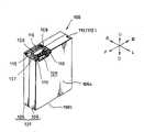
图1是一透视图,表示了根据本发明的电池组即将被安装到一摄像机上时的状态;1 is a perspective view showing a state in which a battery pack according to the present invention is about to be mounted on a video camera;
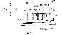
图2是从右侧对电池装入部分所作的正视图;Fig. 2 is a front view of the battery loading part from the right side;
图3是沿图2中的III-III线对电池装入部分所作的放大的剖视图;Fig. 3 is an enlarged cross-sectional view of the battery loading part along line III-III in Fig. 2;
图4是电池组的分解透视图;Figure 4 is an exploded perspective view of the battery pack;
图5中的透视图表示了电池组的整体构造;The perspective view in Figure 5 shows the overall structure of the battery pack;
图6是电池组的轴测视图,该视图是从与图5不同的角度对电池组的整体结构进行观察所得的;Fig. 6 is an axonometric view of the battery pack, which is obtained by observing the overall structure of the battery pack from a different angle from Fig. 5;
图7是一个放大视图,表示了将电池组分解后从上方观察所见到的结构;Fig. 7 is an enlarged view showing the structure seen from above after the battery pack is disassembled;
图8中的放大视图是对电池组的俯视图;The enlarged view in Figure 8 is a top view of the battery pack;
图9是从右侧进行观察所得到的放大视图,在该图中,电池侧接线端的一部分被分解开,且在上下方向上将各个分解部分相互移开;Fig. 9 is an enlarged view viewed from the right side, in which a part of the battery side terminal is disassembled, and the disassembled parts are moved away from each other in the up and down direction;
图10A和10B是电池装入部分中的放大透视图,其中,图10A表示了当主体侧接线端的保护板被转动后的状态;图10B表示了主体侧接线端的保护板位未被转动时的状态;10A and 10B are enlarged perspective views of the battery loading part, wherein, FIG. 10A shows the state when the protective plate of the main body side terminal is turned; FIG. 10B shows the state when the protective plate of the main body side terminal is not turned. state;
图11是一锁止机构的放大透视图,图中,该锁止机构处于已从电池装入部分拆下的状态;Fig. 11 is an enlarged perspective view of a locking mechanism in a state where it has been removed from the battery loading section;
图12中的放大透视图表示了拆卸下来后的锁止机构;The enlarged perspective view in Figure 12 shows the locking mechanism after it has been disassembled;
图13是从前方观察所得到的一个放大视图,在图中,表示了当电池组被安装到电池装入部分、或从电池装入部分中拆出时外观形状一部分的截面结构,图14到图16表示了电池组装入、拆出时的情形,但该视图表示的是处于装入过程的初始阶段时的情形;Fig. 13 is an enlarged view obtained from the front. In the figure, it shows the cross-sectional structure of a part of the appearance shape when the battery pack is installed in the battery loading part or removed from the battery loading part. Fig. 14 to Figure 16 shows the situation when the battery pack is inserted and removed, but this view represents the situation when it is in the initial stage of the insertion process;
图14表示了电池组处于装入过程的中间阶段时的情形;Figure 14 shows the situation when the battery pack is in the middle of the loading process;
图15表示的是当电池组处于装入过程的最终阶段时的情形;Figure 15 shows the situation when the battery pack is in the final stage of the loading process;
图16表示了在拆出电池组时的外观形状,图中,电池组的一部分处于被一防弹起杆顶高的状态;Fig. 16 shows the appearance shape when the battery pack is taken out, in the figure, a part of the battery pack is in a state of being lifted by a bulletproof rod;
图17中的放大视图是电池侧接线端的俯视图;The enlarged view in Figure 17 is a top view of the battery side terminals;
图18中的放大视图是电池侧接线端的左视图;The enlarged view in Figure 18 is a left side view of the battery side terminal;
图19中的放大视图是电池侧接线端的后视图;The enlarged view in Figure 19 is a rear view of the battery side terminals;
图20是沿图18中的XX-XX线对电池侧接线端所作的放大剖视图;Figure 20 is an enlarged cross-sectional view of the battery side terminal along the line XX-XX in Figure 18;
图21是沿图19中的XXI-XXI线对电池侧接线端所作的放大剖视图;Fig. 21 is an enlarged cross-sectional view of the battery side terminal along the line XXI-XXI in Fig. 19;
图22是主体侧接线端放大的左视图;Figure 22 is an enlarged left view of the terminal on the main body side;
图23是主体侧接线端的仰视放大图;Figure 23 is an enlarged bottom view of the terminal on the main body side;
图24是沿图22中的XXIV-XXIV对主体侧接线端所作的放大剖视图;Fig. 24 is an enlarged sectional view of the main body side terminal along line XXIV-XXIV in Fig. 22;
图25是沿图22中的XXV-XXV对主体侧接线端所作的放大剖视图;Fig. 25 is an enlarged cross-sectional view of the main body side terminal along XXV-XXV in Fig. 22;
图26是对电池侧接线端和主体侧接线端所作的放大剖视图,图中表示了两接线端是如何相互结合到一起的,且该视图表示了一初始结合阶段,在该阶段中,一引导件处于即将进入到引导槽中的状态;Figure 26 is an enlarged cross-sectional view of the battery side terminal and the main body side terminal, showing how the two terminals are bonded to each other, and the view showing an initial bonding stage in which a guide The part is in a state about to enter the guide groove;
图27表示了处于结合过程的中间阶段时的状态,在该状态中,接触部分即将与一接触件相接触;Fig. 27 has represented the state when being in the middle stage of bonding process, and in this state, contact portion is about to be contacted with a contact member;
图28表示了结合完成时的状态;Figure 28 shows the state when the combination is completed;
图29是沿图28中的XXIX XXIX线所作的放大剖视图;Figure 29 is an enlarged cross-sectional view made along the line XXIX XXIX in Figure 28;
图30是沿图28中的XXX-XXX线所作的放大剖视图;Figure 30 is an enlarged sectional view made along the XXX-XXX line in Figure 28;
图31与图32、33一道表示了对接线端元件和接线构件的材料以及镀层材料的试验结果,该附图中的结果列表涉及的指标是接触阻抗;Figure 31, together with Figures 32 and 33, shows the test results of the materials of the terminal element and the wiring member and the coating material, and the index related to the result list in the accompanying drawing is contact resistance;
图32中的结果列表针对的是接合力;The result listing in Figure 32 is for engagement forces;
图33中的结果列表涉及的是脱开力;The results tabulation in Figure 33 refers to disengagement force;
图34是对接触部分所作的放大剖视图,在图示的状态中,该接触部分以标准姿态夹持在两接触件之间;Fig. 34 is an enlarged cross-sectional view of the contact part, in the illustrated state, the contact part is clamped between two contact members in a standard posture;
图35是对接触部分所作的放大剖视图,在图示的状态中,接触部分以向一个方向偏移的姿态夹持在两接触件之间;Fig. 35 is an enlarged cross-sectional view of the contact part. In the illustrated state, the contact part is clamped between two contact pieces in a posture offset in one direction;
图36中的图线表示了接触件位移量与接触压力之间的关系;The graph in Figure 36 shows the relationship between contact displacement and contact pressure;
图37与图38至图40一起说明如何根据多种类型的区别标签和阻卡部分的组合情况来判断是否允许装入,且该附图中表示出了I型阻卡部分与对应区别标签之间的关系;Figure 37, together with Figures 38 to 40, illustrates how to judge whether to allow loading according to the combination of various types of distinguishing labels and blocking parts, and the accompanying drawing shows the difference between the I-type blocking part and the corresponding distinguishing label relationship between
图38表示了II型阻卡部分与对应区别标签之间的关系;Figure 38 has shown the relationship between the Type II resistance card part and the corresponding distinguishing label;
图39表示了III型阻卡部分与对应区别标签之间的关系;Figure 39 has shown the relationship between the Type III blockage part and the corresponding distinguishing label;
图40表示了IV型阻卡部分与对应区别标签之间的关系;Figure 40 has shown the relationship between the IV type resistance card part and the corresponding difference label;
图41中的透视图表示了电池组上的一个主要部分,图中表示了电池组上要被锁止部分的一种变型例;The perspective view among Fig. 41 has shown a main part on the battery pack, has shown a modification of the part to be locked on the battery pack among the figure;
图42中的透视图表示了电池组上的一个主要部分,图中表示了电池组上要被锁止部分的另一种变型例;The perspective view among Fig. 42 has represented a main part on the battery pack, has shown another modification of the part to be locked on the battery pack among the figure;
图43中的透视图表示了电池组上的一个主要部分,图中表示了电池组上要被锁止部分的又一种变型例;The perspective view among Fig. 43 has represented a main part on the battery pack, has shown yet another modification of the part to be locked on the battery pack among the figure;
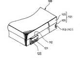
图44是根据本发明的电池组的透视图,表示了电池组即将被安装到一电子设备的电池装入部分前的状态;44 is a perspective view of a battery pack according to the present invention, showing a state before the battery pack is mounted to a battery loading portion of an electronic device;
图45与图46至图48均为透视图,它们一起顺序说明电池组的组装过程,附图45表示电池侧接线端是如何连接到一电路板上的外观状态;Fig. 45 and Fig. 46 to Fig. 48 are all perspective views, and they sequentially illustrate the assembly process of the battery pack together. Accompanying drawing 45 shows how the terminal on the battery side is connected to a circuit board in appearance;
图46是所述电路板如何钎焊到电池单元上的外观图;Figure 46 is an external view of how the circuit board is soldered to the battery cell;
图47是所述电池单元如何安装到一底面壳体中的外观图;Fig. 47 is an external view of how the battery unit is installed in a bottom case;
图48中的外观图表示了一顶面壳体是如何与底面壳体相结合的;The external view in Figure 48 shows how a top shell is combined with a bottom shell;
图49是一电子设备的水平剖面图,表示了电池组是如何安装到该电子设备中的外观状态,且该视图对应于电池组安装到该电子设备中之前的状态;Fig. 49 is a horizontal sectional view of an electronic device, showing the appearance state of how the battery pack is installed in the electronic device, and this view corresponds to the state before the battery pack is installed in the electronic device;
图50表示了电子设备中被装入电池组后的状态;Fig. 50 has represented the state after being loaded into battery pack in the electronic equipment;
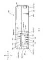
图51是电池组的纵向剖面图;以及Figure 51 is a longitudinal sectional view of the battery pack; and
图52A-52D是电池组以及电池装入部分的正视图,用于说明二者之间的关系,图中,电池组已经被装入到后者中、或即将被装入到后者中。52A-52D are front views of the battery pack and the battery loading part for illustrating the relationship between the two. In the figure, the battery pack has been loaded into the latter, or is about to be loaded into the latter.
具体实施方式Detailed ways
下文将结合附图所示的实施例对一种用于防止将待装器件错误安装到主体侧设备上的方法、一种待装器件、以及一种电池组进行详细地描述。A method for preventing a device to be installed from being wrongly installed on the device on the main body, a device to be installed, and a battery pack will be described in detail below with reference to the embodiments shown in the drawings.
另外,附图所示实施例对应于这样的情况:本发明应用在如何将电池组装入到摄像机中的结构上,其中,此处的“摄像机”对应于权利要求范围内所述的“主体侧设备”,“电池组”则对应着权利要求范围内所述的“待装器件”。此外,下文提到的“摄像灯”、“充电器”对应于“主体侧设备”,而“干电池组”则对应于权利要求范围内所述的“待装器件”。In addition, the embodiments shown in the drawings correspond to the case where the present invention is applied to the structure of how to incorporate the battery pack into the video camera, wherein the "camera" here corresponds to the "main body side" described in the scope of the claims. "equipment" and "battery pack" correspond to the "device to be installed" described in the scope of the claims. In addition, the "camera light" and "charger" mentioned below correspond to the "device on the main body", and the "dry battery pack" corresponds to the "device to be installed" in the scope of the claims.
另外,将在下文中描述的摄像机属于这样的类型:其具有一透镜筒体,在正常的使用状态下,该透镜筒体位于摄像机主体的上部,在该摄像机的右侧面上,可拆卸地安装了一电池组。为此目的,也是在下文中,将以该方向作为标准进行描述,这就意味着:在各个视图中用箭头符号指代的U方向、D方向、L方向、R方向、F方向以及B方向分别是指向上方向、向下方向、向左方向、向右方向、前方和后方。另外,电池组的定向(即方向性)在最初时并不是唯一的,但为了对电池组装入到上述摄像机中的情况进行说明,对定向(方向性)相同的电池组展开讨论。In addition, the video camera that will be described hereinafter is of the type that has a lens barrel located on the upper part of the camera main body in a normal use state, on the right side of the video camera, detachably mounted A battery pack. For this purpose, also in the following, this direction will be used as a standard for description, which means that the U direction, D direction, L direction, R direction, F direction and B direction indicated by arrow symbols in each view are respectively Refers to an upward direction, a downward direction, a leftward direction, a rightward direction, front and rear. In addition, the orientation (directivity) of the battery pack is not unique initially, but in order to explain the case where the battery pack is incorporated into the camera described above, battery packs with the same orientation (directivity) will be discussed.
摄像机1包括:一矩形的立体状摄像机主体2;一透镜筒体3,其设置在摄像机主体2的上部;一显示板(图中未示出),其设置在摄像机主体2的左侧面上;以及其它的部件。
此外,在摄像机主体2的右侧面上设置了一电池装入部分10,该部分10被四个框架体(即一前框架体11、一后框架体12、一上框架体13、以及一下框架体14)包围着(可参见图1和图2)。In addition, a
当从前方进行观察时,电池装入部分10呈现为矩形,且其被制成略大于电池组100的正向投影面积。另外,在前框架体11内表面11a(背面)和后框架体12内表面12a(前面)上靠近上端和下端的位置处分别设置了多个小的凸肋16,这些凸肋在左右方向上延伸,尽管凸肋的突起量很小,但凸肋被制成其突起量随着靠近电池装入部分的底面15而略微增大,即被制成逐渐变细的结构。在底面15上相互正对的两凸肋16之间的间隔距离被制成约等于或略小于电池组的前后尺寸,即宽度(参见图3)。The
在构成电池装入部分的上框架体13的内侧面13a的一侧上设置了一接线端30(下文将称为主体侧接线端),其用于与上述电池组100上的接线端120(下文将称为电池组侧接线端)进行连接,并在下框架体14的中间部位处设置一锁止机构40(参见图1),用于将电池组100锁固在电池装入部分10中。On one side of the
首先,将对摄像机1所使用的电池组100进行说明。First, the
电池组100包括:一矩形立体状的电池壳101,两电池单元102、102,它们安装在电池壳101中;一衬底104,在该衬底上安装有一集成电路(IC)芯片103,用于计算和存储电池组的剩余电量及其它参量;以及一电池侧接线端120,其被连接到衬底104上,用于与主体侧接线端30相连接(参见图4)。The
在本文中,所述电池组100是多种型号的电池组,这主要是因为各种电池组的容量不同,图1、3,图9,图13和图16中的电池组属于标准类型的电池组,在多种电池组100中,这种电池组外部结构尺寸最小(即厚度最薄)。Herein, described
从而,电池壳是由一前壳105和一后壳106组成的(参见图4),且对于多种型号的电池组100,尽管前壳105的尺寸(厚度)对于不同的电池组100是不同的,但后壳106的尺寸都是相同的(参见图37到图40)。Thereby, the battery case is made up of a
在后壳106上表面的前部上,制出了一个凹面107,该凹入部分是一个低于其它部分的凹缺,并在凹面107处制有一矩形的切口108,该切口向前表面侧(即图中的右向)和背表面侧(即图中的左向)开口,上述的电池侧接线端从前表面侧(图中右向)滑入,而连接到该矩形切口108中。连接到矩形切口108中的电池侧接线端120的上表面与除凹面107之外的其它部分等高(参见图9)。On the front part of the upper surface of the
在后壳106的矩形切口108的前后边缘处分别制有向上突起的凸肋109、109(下文称为接线端定位凸肋),它们在图中的左右方向上延伸,且接线端定位凸肋109、109的左端并没有延伸到后壳106的背面106a,而是终止于一个从背面106a略微向右的位置处,这两个接线端定位凸肋的上表面与后壳106上除电池侧接线端和凹面107之外的其它部分等高(参见图7)。At the front and rear edges of the
另外,两接线端定位凸肋109、109之间的间隔距离被制成约等于上述电池侧接线端120前后方向上的尺寸,且两接线端定位凸肋109大致在向右的方向上、从连接后的电池侧接线端的右侧边缘部分延伸出,并在电池侧接线端120的左端处一体地制有小突出条110,它们在相反的方向上延伸。制在电池侧接线端120附近的、诸如小突出条110、110和上述接线端定位凸肋109、109等的突起部分被作为区别标签111、111、…,用于区别电池组100的类型,对此内容下文将进行描述(参见图7)。In addition, the distance between the two
当前壳105与后壳106结合到一起时,上述接线端定位凸肋109的右端部109a从后壳106一侧向外悬伸出,且当电池组100被装入到摄像机主体2上的电池装入部分10中时,接线端定位凸肋109的右端部109a就成为了上侧待锁止部分112中的一个部分,关于电池组装入到电池装入部分方面的内容,在下文将进行描述(参见图8)。When the
在后壳106上表面的后侧拐角部分处,设置了一个相对较小的凹面部分113,该凹面部分向上方和后方开口,当电池组100被装入到电池装入部分10中时,该小凹面部分113就变为了上侧待锁止部分112中的一个部分(参见图8)。At the rear side corner portion of the upper surface of the
另外,在后壳106的底面106b上制有一在前后方向上延伸的条形凹入的待锁止槽114,摄像机主体2上锁止机构40的一个锁爪41会锁定在该锁止槽中(下文将对此进行描述),且待锁止槽114还作为电池组100下侧的锁止部分112(参见图6)。In addition, on the
以这样的方式,通过在电池组一侧后壳106(即在一个器件)的各个部位处设置了待锁止部分112,即接线端定位凸肋的右端部109a、凹入部分113以及待锁止槽114,就可以提高电池组100被装入到电池装入部分10中时的定位精度(参见图15)。In such a manner, by being provided with the
也就是说,随着后壳106的背面106a(左侧面)与一底面15相接触(参见图15),且与此同时,随着电池组一侧各个部位处的待锁止部分112(即接线端定位凸肋的右端部109a、凹入部分113和锁止槽114)被电池装入部分10一侧的对应锁止部分(即下文将要进行描述的悬垂部分17、小凸起部分20以及锁爪41)锁定,电池组100就被装到了电池装入部分10中。如果在多个器件上设置各个待锁止部分112、112…,例如在前壳105和后壳106上设置这些待锁止部分,那么,如当壳105与后壳106被不够精确地组装到一起时,则会在锁紧状态时出现游隙,且电池侧接线端与主体侧接线端30之间的连接状态也会发生问题。That is to say, as the
因而,对于在电池组100上的情况,通过将上述用于进行定位的多个待锁止部分112集中制在其中一个部件(即后壳106)上,就可以提高电池组100处于安装状态时的定位精度,这样就可以降低后壳106与前壳105进行结合时的精度要求。Thus, for the situation on the
此外,在前壳105与上述电池侧接线端120相对应的前上部分处,制出了一个凹陷部分115,其高度基本上与后壳106上的凹面部分107等高,且在凹陷部分115的左侧边缘处制有一个接线端加压凸肋116,其用于从右侧对电池侧接线端120进行加压(参见图7到图9)。In addition, at the front upper part of the
接线端加压凸肋116在前后方向上的长度被制成与上述后壳106上两接线端定位凸肋109、109之间的间隔距离大致相同,也就是说,几乎与电池侧接线端120在前后方向上的尺寸相同,因而,当前壳105被组装到后壳106上时,接线端加压凸肋116就会位于上述的两接线端定位凸肋109、109之间,并从左侧对电池侧接线端120进行顶压,后壳106上的两接线端定位凸肋109、109比用作待锁止部分112的两接线端加压凸肋116略微向右伸出一些(参见图8)。The length of the
对于标准容量型号的电池组100,两个矩形立体状的电池单元102、102排成一列地包封在一电池壳中,且上述的衬底104被安装在电池单元的上部,而上述的电池侧接线端120和IC芯片103则分别安装在衬底104的前部和后部(参见图4)。For the
按照这样的方式,由于电池侧接线端130的设置位置相对于电池组100在一个方向上有偏移,所以就可在其相反一侧形成相对较大的空间,从而就能在该空间中设置诸如IC芯片103等的电子部件,进而提高对空间的利用率。具体来讲,当矩形立体状的电池单元102被设置到电池壳101中时,未留有任何的死角空间,从而能将电池单元102、102有效地布置到电池组100中。尽管在衬底104上为电池侧接线端120以及集成电路芯片103等从电池单元突出的元件留出安装空间是有困难的,但通过如上述那样将电池侧接线端120设置在相对于电池组100偏移的位置上,就能实现空间的有效利用(参见图4和图7)。In this way, since the installation position of the
另外,由于电池侧接线端120被设置在相对于电池组偏移的位置上,所以可防止将电池组100错误地安装到摄像机主体2上。In addition, since the
与此同时,下文将对电池侧接线端120、作为电池侧接线端120上接纳侧的矩形切口108、以及组装方法进行详细描述。Meanwhile, the battery-
下面,将对摄像机主体2的电池装入部分10作详细的描述。Next, the
摄像机主体2上电池装入部分10的上下向尺寸被制成略大于上述电池壳101的后壳106的厚度(即在左右方向上的厚度)。因而,在电池组100被安装到电池装入部分10上的状态下,后壳106就位于电池装入部分10的内部,且前壳105上的几乎所有部分都从摄像机主体2中突出(参见图3和图15)。The vertical dimension of the
在与上述电池侧接线端120相对的位置处设置有一主体侧接线端30,也就是说:主体侧接线端30设置在上框架体13的内表面(即其下表面)与底面15之间的角部分处,或者也可以讲是位于前上方的斜角位置处(参见图10)。A main
在与上述主体侧接线端30的设置位置相对应的区域,制出了一个向下方悬伸的部分17,其中所述的区域是上框架体13内表面上的一个开口侧边缘(右侧边缘),悬垂部分17与电池装入部分10的底面15之间的尺寸被设计成和上述后壳106的背面106a与接线端定位凸肋109右端部之间的距离相同(参见图15)。In the area corresponding to the setting position of the above-mentioned main
结果:当电池组100被装入到电池装入部分10中时,接线端定位凸肋109的右端部分就会被悬垂部分17卡住,且在二者之间没有游隙。相应地,就可以以这样的状态实现锁止:电池组100上部的前方区域内没有任何游隙(参见图15)。Result: When the
从悬垂部分17的后部向电池装入部分10的底面(向左)整体地制出一突出条18(下文中将其称为“阻卡突出条”),且该阻卡突出条18的末端部分延伸到与底面15分开合适距离的位置处(参见图10),从而不与上述电池组100后壳106上的上述区别标签111发生干涉。A protruding strip 18 (hereinafter referred to as "blocking protruding strip") is integrally made from the rear portion of the overhanging
该阻卡突出条18与下文将要描述的、设置在主体侧接线端30附近的小突起部分18a用作阻卡部分19、决定电池组100能否被装入。与此同时,由于上述的阻卡部分19被制成不与电池组100上的区别标签111相干涉,所以允许将电池组100装入到电池装入部分10中,尽管在某种设备,例如在摄像灯150中(此时将不装入低容量的电池组100),可装入这种电池组100,但存在由于电池组100的容量不同而不允许装入的情况。The
在这样的情形中,将上述阻卡部分19设计成这样:其在电池装入部分10底面16的附近上延伸,从而与上述的区别标签111相干涉,由此来阻挡电池组100而不允许其装入。是否允许电池组100装入是由上述电池组100一侧的区别标签111与上述阻卡部分19之间位置关系的形式来确定的,下文将对此有详细的描述。In such a case, the above-mentioned
在与上述后壳106的小凹面部分113相对应的位置处,制有一小凸起部分20,其能与小凹面部分113精确地结合(参见图10),该位置是电池装入部分10的上框架体13的内表面13a(即其下表面)与后框架体12内表面12a(即其前表面)的拐角部位,且小凸起部分20在电池装入部分10的底面15上的设置位置与小凹面部分113在后壳106后面106a上的设置位置相一致。结果:当电池组100被装入到电池装入部分10中时,可以没有任何游隙地锁止电池组上部的后侧区域。At the position corresponding to the small
在电池装入部分10底面15下部的中央位置处制有一个矩形的孔洞21(下文将其称为“上推板设置孔”),且在下框架体14的内表面(即其上表面)上制有一切口部分22(下文将其称为“锁止杆设置孔”),该切口部分22被制成与上述的上推板设置孔21延续为一体(参见图2)。A rectangular hole 21 (hereinafter referred to as "the upper push plate setting hole") is formed at the central position of the
锁止机构40包括:一锁止杆42,其具有一锁爪41,其与制在电池组100底面上的待锁止槽114相接合;一上推板43,其用于在使电池组100脱开的方向上对电池组100的底面106a施加压力;一防弹跳杆44,用于在利用上述的锁止杆42解除对电池组100的锁止时、防止电池组100向上弹出,这些锁止杆42、上推板43以及防弹跳杆44通过一底板45而可转动地支撑在同一轴上,其中的底板位于下框架体14和底面15间拐角部分的内侧上(参见图11和图12)。The
这样,底板45就处于下框架体14的内侧,并固定在下框架体14上,上述的锁止杆42被设置在下框架体14的上述锁止杆设置孔22中,上推板43位于上推板设置孔21中,而防弹跳杆44则处于矩形切口46(下文将其称为“防弹跳杆设置孔”)中,该切口46与锁止杆设置孔22连为一体。Like this,
此外,在一转轴47上套装着一螺旋扭力弹簧48的卷簧部分48a,转轴47可转动地支撑着锁止杆42、上推板43、以及防弹跳杆44,弹簧48的一支臂部分48b作用在锁止杆42上,其另一支臂部分48c作用在上推板43上,由此促使锁止杆42在向上的方向上转动,并促使上推板43在向右的方向上转动(参见图12)。In addition, a
锁止杆42适于具有这样的外观形状:其侧面的整体形状为字母L型,且其一上表面构件49被制成变为上述下框架体14内表面(即其上表面)的一部分,截面形状为三角形的锁爪41被制在前后方向上,并延伸到这样一个位置处:其偏离上表面构件49的转动中心,在右侧面的下部制有一操作部分50,用于对锁止杆42进行操作(参见图11和图12)。The locking
因而,锁爪41就被制成了这样:其略微地在向右的方向上(前侧)从电池装入部分10的底面15偏移(在前侧),且距离底面15的尺寸等于距离上述电池组100的待锁止槽114的底面106a的距离,因而,当锁爪41与待锁止槽114接合时,电池组100可被自然地紧压到电池装入部分10的底面15上(参见图15)。Thus, the locking
另外,在锁止杆42的上表面部件49的左右两侧部分,分别设置了两个小的突起51、51,它们与下框架体14的锁止杆设置孔22的两边缘部分相接触,且这两个突起51、51在上述螺旋扭力弹簧48的促动下、从内侧与上述锁止杆设置孔22的边缘部分相卡撞,从而被阻卡住。在这样的状态下,上表面部件49的上表面与下框架体14的上表面是平齐的。In addition, two
上推板43上一体地制有两小部件52、52,它们从转动中心向下伸出,且这两个小部件受所述螺旋扭力弹簧48的作用而与上述底板45相接触,从而被阻卡住。在此状态下,上推板43处于这样的状态:其从上推板设置孔21向右方突起(参见图12)。Two
防弹跳杆44具有一螺旋压缩弹簧54,其被压缩在一转动端部的下表面与一突出件53之间,因而,防弹跳杆44就与所述锁止杆42类似,也被可转动地向上顶(参见图13到图16)。顺便说明:在图13到图16中,所述的电池侧接线端120和主体侧接线端30都没有被绘出。The
防弹跳杆44的转动端上制有一卡爪部分55,该部分向上突起,在防弹跳杆44的底端部分一体地制有一个转动挡件56,其向前方突出。利用转动挡件56与制在衬底45上的一个限位件57撞卡在一起,就阻挡了防弹跳杆44在所述螺旋压缩弹簧54作用下转动。在该状态下,上述卡爪部分55从下框架体14的上表面向上突出(参见图13到图16)。On the rotating end of
除此之外,将防弹跳杆44的卡爪部分55形成为比锁止杆42的锁爪41更靠右(参见图13到图16)。In addition to this, the
按照这样的方式,当电池组100处于未被装入到电池装入部分10中的状态时,锁止杆42的锁爪41和防弹跳杆44的卡爪部分55就从下框架体14的上表面向上突出,且上推板43处于从电池装入部分10的底面向右突出的状态(参见图13或图16)。In this manner, when the
这样,当电池组100将要被安装到电池装入部分10上时,将以如下的方式执行一个过程,且通过上述锁止机构将装入到电池装入部分10中的电池组100保持在锁止状态下。Thus, when the
首先,电池组100以其上部倾斜的姿态插入到电池装入部分10中,且电池侧接线端120(包括后壳105上的接线端定位凸肋109和前壳105上的接线端加压凸肋116)被滑入到电池装入部分10的悬垂部分17的内侧。因而,如上文提到的那样:由于位于电池组100一侧的区别标签111并不与电池装入部分10一侧的构件(阻卡部分19)发生干涉,所以电池组100的电池侧接线端120、接线端定位凸肋109和接线端加压凸肋116就能深深地滑入到悬垂部分17中(参见图13)。First, the
此时,上述电池侧接线端120的三个接线端构件122、122、122以及主体侧接线端30的三个接线元件31、31、31(图中未示出)就分别相互结合在一起。At this time, the three
除此之外,如下文将要详细描述的那样,通过在电池组100一侧设置区别标签111、并在电池装入部分10一侧设置可与区别标签相互干涉的阻卡部分19,上述电池侧接线端120就不能深滑到电池装入部分10的悬垂部分17中。因而,电池侧接线端120的接线端构件122就将不能与主体侧接线端30上的接线元件31相结合。In addition, as will be described in detail below, by setting a
而且,如果即使在电池装入部分10上的阻卡部分19与电池组100的区别标签111相干涉的条件下也将电池组100强行装入到电池装入部分10中,由于电池装入部分10的上框架体13会随着上述区别标签111对阻卡部分19的挤压而发生弯曲,所以存在电池组被装入到电池装入部分中的偶然可能性。Moreover, if the
但在这样的情形中,由于阻卡部分19和区别标签111被制在两接线端120、30的附近,所以主体侧接线端30会在其受到压迫的方向上后撤,从而造成两接线端实际上并不相互接合。因而,接线元件31和接线端构件122并不能相互接触,由此避免电接触。But in such a situation, since the blocking
然后,以电池组100的上部(即电池侧接线端120被悬垂部分17锁止的部分)作为转动支点,电池组100的下部向左转动,这样,电池组100就装到了电池装入部分10中(参见图14和15)。Then, with the top of the battery pack 100 (i.e. the part where the
此时,上述锁止机构40的防弹跳杆44上的卡爪部分55被电池组100的左下侧向下顶,卡爪部分55与待锁止槽114相接合(参见图14)。At this time, the
另外,随看电池组100的下部被压向电池装入部分100,上述防弹跳杆44的卡爪部分55就会被待锁止槽114的边缘部分推开,且与此同时,锁止杆42的锁爪41被电池组的左下侧边缘部分(即底面一侧的角部分)所推顶,然后,锁爪41就与待锁止槽114相接合,由此完成了电池组100的装入过程(参见图15)。In addition, as the lower part of the
此外,在锁爪41与待锁止槽114接合之前,电池组100的底面106a使上推板43在向左的方向上转动,从而使电池组100的下表面106a几乎是面对面地与电池装入部分10的下表面15相接触(参见图15)。In addition, before the locking
因而,这些锁止杆42、防弹跳杆44、以及上推板43就克服上述螺旋扭力弹簧48或螺旋压缩弹簧54的弹力作用而发生了转动。Thus, these locking
此时,电池侧接线端120的接线端构件122就与主体侧接线端30上的接线元件31相互对接到了一起,与此同时,设置在电池组100上部的接线端定位凸肋109的右端部分109a与悬垂部分17相接合,且电池组100上的凹面部分113(待锁止部分112)与电池装入部分10上的小凸起部分20相接合。At this time, the
结果,在电池组100的上部,接线端定位凸肋109的右端部109a(待锁止部分112)与悬垂部分17相接合,小凹面部分113(待锁止部分112)与小凸起部分20相接合,而在电池组100的下部,锁爪41和待锁止槽114相接合,这样就将电池组100固定在了电池装入部分10中(参见图15)。As a result, at the top of the
锁止杆42的锁爪41和防弹跳杆44的卡爪部分55在向上的方向上顶压着电池组100,从而将电池组100顶向上框架体13,这样就实现了电池组100在上下方向上的定位(参见图15)。The locking
结果:电池侧接线端120被紧压到主体侧接线端30上,从而保证了接线端构件122与接线元件31之间稳定的结合状态。尤其是:电池侧接线端120和主体侧接线端30被设置在相对于电池组100向前偏移的位置上,而且,由于防弹跳杆44在前后方向上被设置在从中间部位向前偏移的位置处,也就是说,防弹跳杆44被设置在与两接线端120、30相对的位置处,电池组100被卡爪部分55向上推顶,从而可确保接线端构件122与接线元件31稳定地结合到一起(参见图2)。Result: The battery-
另外,由于电池组100的下部被上推板43向右顶压,且被锁爪41与待锁止槽114之间的接合关系卡住,所以实现了电池组100在装入方向(即左右方向)上的定位,此外,由于电池组100受到制在前框架体11内表面11a(即其背面)、以及后框架体12的内表面12a(即其前表面)上的小凸肋16、16的限制,由此实现了在前后方向上的定位(参见图3)。In addition, since the bottom of the
已被装入到摄像机主体2的电池装入部分10中的电池组100是按照如下的方式从摄像机主体2中拆出的。The
也就是说:首先,通过用手或手指按压操作部分50就能对锁止机构进行解锁(参见图16)。That is to say: first, the locking mechanism can be unlocked by pressing the operating
当锁止杆42被操作时其克服螺旋扭力弹簧48的弹力而在向下的方向上转动,由此与电池组100上的待锁止槽114脱开。When the locking
当锁爪41与电池组100脱开时,电池组100的下部就会被上推板43向左推移,因而,从电池装入部分10的底面15升起(参见图16)。When the locking
此时,当电池组100的下部从底面15略微浮高时,防弹跳杆44的卡爪部分55与待锁止槽114相接合。结果:尽管电池组100从电池装入部分10中突出,但由于防弹跳杆44的卡爪部分55被待锁止槽114抓住,所以电池组100并不会在不经意间猛然弹出。尤其是:当摄像机1处于上述的定向位置时(即在正常拍摄的姿态时),即使对电池组100进行解锁,防弹跳杆44的卡爪部分55也会被待锁止槽114抓住,因而,电池组100并不会从电池装入部分10中脱出,从而可防止电池组100掉落下去。At this time, when the lower portion of the
然后,通过抓住下部已被弹高的电池组100,并在使电池组100脱开的方向上(向右)用手把电池组拉出,则由于防弹跳杆44的卡爪部分55与待锁止槽114脱开,所以可容易地将电池组100从电池装入部分10中拆出。Then, by grasping the
下面,将详细地介绍电池侧接线端120及其组装到电池组100上的过程。Next, the battery-
如上所述,电池侧接线端120由一接线端壳体121和三个接线端构件122、122、122构成,接线端构件122是通过内嵌模压的方法安装到接线端壳体121中的,接线端壳体121的外观形状呈现为一扁平的立方实体,并制有向上和向左开口的五条沟槽123、123、124、124、124(参见图17到图19)。As mentioned above, the
在上述的五条沟槽中,位于前后两侧的两条沟槽123、123的宽度大于其它三条沟槽124、124、124的宽度,且它们的长度和深度也大于其它三条沟槽124、124、124,沟槽123被用作相对于主体侧接线端30进行定位的引导槽(参见图17-19),下文将对此作进一步的描述。Among the above five grooves, the width of the two
此外,上述五条沟槽的中间三条沟槽124、124、124用作接线端设置槽124、124、124,且该各个沟槽中设置了一对相互正对的接触件125,并在接线端设置槽124、124、124内部形成了用于容纳上述接触件125、125的容纳空间126(参见图17、18)。顺便提及,在图17和图18中,只用虚线表示出了一个接线端构件122,而其它的两个接线端构件122、122则被略去了。In addition, the middle three
另外,对这两个引导槽123、123以及接线端设置槽124、124开口侧的边缘进行了倒角处理,例如将边缘倒角处理成R角、圆角、锥角等形状。因而,如下文将要描述的那样,主体侧接线端30的引导件32和接线元件31、31、31能容易地插入到这些沟槽123、123、124、124、124中(参见图26到图28)。In addition, the edges of the opening sides of the two
电池侧接线端120的各个接线端构件122是由如下部件一体制成的:一对相互正对的接触件125、125;将两接触件125连接起来的基部元件127;以及一引线元件128。其中的引线元件128被钎焊到设置于电池壳101上的衬底104上,并从基部元件127沿与接触件125、125相反的方向延伸(参见图21和22)。Each
接触件125、125具有嵌入到上述接线端壳体121中的根部、以及半球形的凸起触点部分125a、125a,两触点部分制在接触件125的末梢部位上,并在相互靠近的方向上突起,两凸起触点部分125a、125a在不受到任何压力作用时,处于相互接触的状态(即所谓的零接触状态)。当对电池侧接线端120的接线端设置槽124进行观察时,只能看到两个凸起触点部分125a(参见图20和21)。The
因而,当一接触部分35被插入到接线端设置槽124中时,只能与两个凸起触点部分125a、125a接触到。无论接触部分35是从两个方向(即左右方向和上下方向)中的那一个方向插入到接线端设置槽124中,由于接触件125、125的弹簧特性在两个方向上是相同的,所以都能确保接线端120和30可靠地接触到一起。当然,尽管在上述实施例中,在将电池组100装到摄像机1上时,只是在左右方向上进行插入,但这种效果局限于仅对接线端的结构进行设计的情况。Therefore, when a
基部元件127在某一位置处是外露的,在该位置处,基部元件连接到接线端壳体121的右侧面上,且引线元件128被弯折成直角状,并沿向右的方向从基部元件127的下边缘延伸出,并基本上与接线端121的底面121a相平齐(参见图20和图21)。The
在接线端壳体121的前后两侧面上制有两个在左右方向上延伸的滑动凸起部分129、129,滑动凸起部分129、129是上述后壳106的矩形切口108的左右两侧边缘,并与制在接线端定位凸肋109下侧的两滑动槽117、117滑动接合,从而将电池侧接线端120支撑到后壳106中(参见图9)。Two sliding
后壳106的滑动槽117、117的左端是盲端,所以当电池侧接线端120与滑动槽117滑动接合时,能对其进行左向定位。也就是说,调整了从后壳106的背面106a到电池侧接线端的位置。The left ends of the sliding
制出了两个切槽130、130,它们分别是位于右侧面与前侧面之间的拐角部位、以及右侧面与后侧面之间的拐角部分,并与上述滑动凸起部分129、129的上侧相毗邻,切槽130、130与制在上述接线端加压凸肋116前后两端的左侧的两突起118、118相接合(参见图9)。Two
因而,该电池侧接线端120具有三个引线元件128、128、128,它们被焊接到上述衬底104的预定位置处(前侧的左拐角部位),并安装在衬底104的前侧左角部上(参见图4和图17)。另外,在衬底104后侧的、未安装电池侧接线端120的预定位置处安装了诸如集成电路芯片103等的电子器件部分(参见图7)。Thus, the
因而,电池单元102、102按照前后对齐成一列的状态结合到一起,并在两电池单元102的顶部连接着上述衬底104,在衬底104上安装着所述的电池侧接线端120、IC芯片103等器件(参见图4)。Therefore, the
然后,将其上已连接了衬底104的电池单元102、102从右侧插入到后壳106中。此时,电池侧接线端120就从右侧滑插到后壳106的矩形切口108中(参见图7)。Then, the
而后,如上述那样,电池侧接线端120的滑动凸起部分129、129被插入到后壳106的滑动槽117、117中(参见图7)。Then, as described above, the
最后,通过将前壳105与后壳106结合到一起而包封了两电池单元102(参见图8)。Finally, the two
此时,前壳105上的突起118、118与后壳106上的切槽130、130相接合,且与此同时,接线端加压凸肋116压在接线端外壳121的右表面上,从而封住了各个接线端构件122上露在右表面上的基部元件127、127、127。然后,对电池侧接线端120执行左右方向的定向,且将电池侧接线端120保持在后壳106与前壳105之间。At this time, the
利用超声焊接的方法将前壳105的开口周缘与后壳106的开口周缘连接到一起,从而完成了前壳与后壳的结合。此外,也可以是用粘接剂、而不是超声焊接的方法来连接两个半壳体。The opening periphery of the
如刚描述的那样,电池组100是由三个部分,后壳106、电池单元102(包括电池侧接线端120、衬底104等器件)、以及前壳105以这样的方式构成的:三部分是沿一个方向组装到一起的。As just described, the
下面,将详细地描述主体侧接线端30与上述电池侧接线端120的结合。Next, the combination of the main
首先,主体侧接线端30被设置在上述的位置上(即位于底面一侧的前拐角部位),其包括:三个接线元件31、31、31,它们从底面15以及上框架体13的内表面13a突起;两个引导件32,它们在前后方向上将三个接线元件31夹在它们之间;可转动地设置在上框架体13上的一保护板,其覆盖各个接线元件31、31、31的上表面(参见图22和23)。First of all, the main
当从前后方向观察时,接线元件31为矩形的扁平板件,且其上边缘和左边缘被嵌入到上框架体13中,一引线部分34从上框架体13中突出(参见图24),从上框架体13中露出的部分(即下边缘和右边缘)用作接触部分35,该接触部分35被夹持在上述电池侧接线端120的两接触件125、125之间,接线元件31的端部边缘被倒角处理。When viewed from the front-to-back direction, the
三个接线元件31、31、31之间的间隔被设计成与上述电池侧接线端120上接线端设置槽124、124、124之间的间隔相同,且各个接线元件31的厚度被制成约为形成在电池侧接线端120中的接线端设置槽124的宽度的一半(参见图22和23)。The spacing between the three
当从前后方向看时,引导件32为矩形,与上述接线元件32的形状类似,并和电池装载部分的上框架13和底面15形成为一体(参见图24)。When viewed from the front-to-back direction, the
此外,设置了两引导接线端32、32,当从前后方向进行观察时,引导接线端32要大于接线元件31的接触部分35,且引导接线端32的板厚度也大于接线元件31的厚度。另外,引导接线端32、32之间的间隔被制成与上述电池侧接线端120上制出的两引导槽123、123之间的间隔相同,每个引导件32、32的板厚被形成得小于上述电池侧接线端120的接线端壳体121的上引导槽123、123的宽度,且引导件32的端部边缘被倒角处理(参见图23)。In addition, two
如上所述,由于引导件32被制成略大于接线元件31的接触部分35,所以在主体侧接线端30即将与电池侧接线端120相结合时,在接触部分35进入到接线端沟槽124中之前,引导件首次进入引导件32的引导槽123中(参见图26)。As described above, since the
保护板33的支撑位置靠近于上框架体13内表面(即下表面)前端部的开口侧边缘(右侧边缘),从而可在上下方向上自由转动(参见图24和25)。The supporting position of the
具体来讲,在上框架体13内表面(下表面)的前端部处制有一凸起状的保护框架13b,且在保护板33的前后两侧边缘处一体地制有两作为支撑轴的突出部分36、36,用于与上述保护框架部分13b的左右两端部分可转动地接合,围绕支撑轴突出部分36布置了一卷簧37。当从后向观察时,保护板33在逆时针方向上受到促动(参见图24和25)。Specifically, a protruding
在保护板33的转动支点部分处设置有转动止挡部分38、38(在图中只表示了其中一个止挡部分),其与上框架体13相接触,用于阻止上述的逆时针转动,当保护板33处于向左下方偏斜(基本上为45°)的状态时,保护板处于逆时针转动时的转动行程的末端(参见图10A、24和29)。此外,保护板33顺时针转动时的转动行程末端位于这样的位置处:保护板33被容纳在上框架体13的保护板容纳部分13b处,并基本上处于水平姿态(参见图10B)。
保护板33在前后方向上的尺寸略小于上述两引导件32、32之间的距离,从而被制成始终可在两引导件32、32之间转动。在与上述接线元件31相对应的位置处,保护板33上制有狭缝39、39、39,这些狭缝向转动端一侧的边缘开口。结果,当保护板33向上转动时,各个接线元件31、31、31就会插入到这些狭缝39、39、39中,从而使得保护板33可转动,同时,使得接线元件31、31、31露出(参见图10、22和23)。顺便提及,图10A表示的是保护板在转动后的状态,而图10B则表示的是保护板未转动时的状态。The size of the
而后,当未在保护板33的转动端上沿逆时针方向施加外力时,位于两引导件32、32之间的拐角部分就处于这样的状态:它们遮挡着保护板33转动端边缘的两侧(参见图25)。另外,在此状态下,上述接线端31的接触部分35、35、35的拐角处于与上述狭缝39、39、39相接合的状态(参见图25)。Then, when no external force is applied in the counterclockwise direction on the rotating end of the
然后,如下文将要详细描述的那样,当电池组100被安装到电池装入部分10中时,电池侧接线端120的接线端壳体121就会顶压上述的保护板33,使其克服螺旋扭力弹簧37的弹力而顺时针转动,并最终定位在上框架体13的保护板接纳部分13b的位置处(参见图29)。Then, as will be described in detail below, when the
结果:主体侧接线端30的接触部分35、35、35被露出,并相对地进入到接线端壳体121的接线端设置槽124、124、124中,从而被夹在各对接触件125、125、125之间,由此建立起电接触(参见图28)。Result: The
以上述方式,当保护板33处于未受外力作用的状态时,由于其覆盖接触部分35、35、35,所以接触部分是不外露的,从而可防止异物粘接到接触部分上(参见图25)。In the manner described above, when the
此外,当在主体侧接线端30部分上出现了任何形式的冲撞时,例如,当电池组100以错误的定位装入时(即错误装入),则就存在这样的可能:电池侧接线端120之外的其它构件碰撞到主体侧接线端30上。In addition, when any kind of impact occurs on the main
即使在这样的情况下,由于引导件32、32、32被制成大于接触部分35,所以外力实际上是作用在引导件32上,而非作用在接触部分35上,从而可防止接触部分35发生变形。Even in this case, since the
另外,当相对较小的异物撞击到主体侧接线端30上时,由于设置了上述的保护板33,所以异物在与接线元件31(接触部分35)相撞之前先与保护板33相撞击,所以外力受到了缓冲,从而接触部分35不会直接受到很大的外力作用。In addition, when a relatively small foreign matter collides with the main
另外,如上所述,由于当向保护板33施加具有前后方向分量的外力时、保护板33处于被夹在两引导件32之间的状态,由于引导件32、32用以支撑保护板33,且由于三个接触部分被插入到三个狭缝39、39、39中,所以,外力分别通过狭缝39、39、39作用在三个接触部分35、35、35上,从而可防止保护板33在前后方向上发生移位。因此,由于外力始终不会作用在接触部分35上,所以,在此方面,可防止接触部分35、35、35发生变形。In addition, as described above, since the
顺便提及,对于上述的实施例中,主体侧接线端30具有:一体地形成在上框架体部分上的引导件32、32;通过内嵌模压方法一体制出的三个接线元件31、31、31或可转动的保护板33。或者,主体侧接线端30具有在预定形状的基件内模制或形成为另一个元件的各个部分,从而将该基件作为接线端连接到上框架体13上。Incidentally, with the above-described embodiment, the main
接下来将描述:当电池组100被装入到电池装入部分10中时,电池侧接线端120如何与主体侧接线端30进行连接。Next, it will be described how the
首先,带有电池侧接线端120(其包括接线端定位凸肋109和接线端加压凸肋116)的电池组100被偏斜定位,从而可驱入到上框架体13的悬垂部分17下方,这样,主体侧接线端30和电池侧接线端120彼此正对。First, the
接下来,当电池侧接线端120被驱入到上述悬垂部分17的下方时(参见图13),主体侧接线端30的引导件32、32就被相对地插入电池侧接线端120的引导槽123、123中(参见图26)。此时,由于引导槽123的开口侧边缘已被倒角处理,且引导件32的端部边缘也被倒角处理,所以很容易将二者结合到一起。Next, when the
在此状态下,引导件32、32处于被略微插入到引导槽123、123中的状态,结果是实现了电池侧接线端120相对于主体侧接线端30的定位。如上所述,在接触件125、125与接触部分35、35、35发生接触之前,由模制构件组成的引导件32、32与引导槽125、125接合,所以通过制造精确的构件就可完成定位。因此,在两接线端120、30的接触件125、125与接触部分35相互接触之前,就能精确地完成两接线端120、30的定位,结果,接触部分35与接触件125在随后以很高的精度接触。In this state, the
从该状态开始,电池组100的下部分发生转动,从而装入到电池装入部分10中。通过使后壳106的待锁止部分被上述悬垂部分17抓住,并以该区作为转动支点,进行电池组100的转动(参见图14)。From this state, the lower portion of the
然后,主体侧接线端30的接触部分35相对插入电池侧接线端120的接线端设置槽124中(参见图27),接触部分与两凸起触点部分125a、125a接触,并将它们推开,从而使接触件125、125发生弹性弯曲,并夹持接触部分35。结果,在电池侧接线端120与主体侧接线端30之间建立了电连接(参见图28)。Then, the
此外,接触部分35与接触件125、125之间的位置关系如下:使接触部分35沿其表面方向相对移动,并且,由于两接触件125、125发生弹性弯曲的方式使末端部分(即凸起触点部分125a、125a)被推开并相互远离、且作用在两接触件之间的力不会过大,所以接触部分35和接触件125、125始终不会变形。In addition, the positional relationship between the
另外,由于电池侧接线端120与主体侧接线端30之间的位置关系如下:在电池侧接线端120的两个方向上开口的接线端设置槽124、124、124与角部近似为直角的扁平板状接触部分35、35、35接触,所以电池侧接线端120可在90度的方向范围内与主体侧接线端30相结合,其中的方向范围包括左右方向和上下方向。In addition, since the positional relationship between the battery-
也就是说,当仅考虑电池侧接线端120与主体侧接线端30的结构时,电池侧接线端120可从左向、下方、或包括上述的方向的左斜下方与主体侧接线端30向结合,这意味着:前者可在大致90度的范围内从任何方向与后者结合,此外,在以这些方向进行的任何结合中,在接触部分35和接触件125、125上都不会作用有太大的力,结果是接触部分35和接触件125、125始终不会变形。That is to say, when only the structure of the battery-
当然,在上述电池组100与摄像机主体2的电池装入部分10的相对位置关系中,由于电池侧接线端120将沿基本向左的方向与主体侧接线端30结合,所以,可以说电池侧接线端120与主体侧接线端30的结构不能充分发挥作用。Of course, in the above-mentioned relative positional relationship between the
但是,由于通过转动将上述电池侧接线端100装入主体侧接线端10中,因而,两接线端130和30的结合并非仅为一个方向上的方向分量,通过采用接线端结构,就可以认为,两接线端120和30的接触部分35和接触件125、125、125在相互结合时不会受到太大的作用力,所以不会产生变形。However, since the above-mentioned battery-
此外,由于凸起触点部分125a、125a设置在接触件125、125的稍部,因此,凸起触点部分125a、125a能与接触部分35接触,还存在这样的可能性:两接线端在90度方向范围内彼此结合,该方向范围包括上述的两个方向。In addition, since the protruding
也就是说,接触部分35进入到接触件125、125之间,并将它们向侧部推动,从而使它们相互远离,但是,由于接触部分35只与凸起触点部分125a、125a接触,所以不论两接线端120、30是在90度范围内的任何方向进行结合,电池装入部分10都能以相同的方式接纳电池组100,其中的90°方向范围包括上述的两个方向。That is, the
此外,由于凸起触点部分125a、125a被设置在接触件125、125的梢部上,所以即使接触件125、125和接触部分35在前后方向的位置有略微的移位,也可以保证两接线端(接触件125、125和接触部分35)之间具有稳固的连接关系。In addition, since the
下面,对于接线端120与30之间的结合关系,对能影响接触件125与接触部分35之间接触状态的接线端构件122的材质以及宽度进行讨论。Next, regarding the connection relationship between the
另外,接线元件31是用黄铜制成的(厚度t=0.35mm),且其接触部分被镀了0.76μm厚的金。此外,为何选择黄铜作为接触件31制造材料的原因在于:黄铜、磷青铜以及铍铜通常被用来制造触点,且还考虑到了成本和可加工性方面的要求。In addition, the
另外,对于其中的镀金,用一层镍作为基层,且考虑到需要提高安全比,设定镍层的厚度为0.75,其中,考虑安全比的原因是:在电池组100与摄像机1的使用状态下,需要频繁地插入和拔出电池组100。In addition, for the gold plating therein, a layer of nickel is used as the base layer, and considering the need to improve the safety ratio, the thickness of the nickel layer is set to 0.75, wherein the reason for considering the safety ratio is: in the use state of the
因而,即使上述的设计被用在摄像机1和电池组100的接线端结构上,凸起触点部分125a也完全能在正常使用中耐受镀金层的磨耗。Therefore, even if the above-mentioned design is used on the terminal structure of the
另外,主要是在接触部分,即接触部分35处镀了0.76μm厚的金,而在引线部分34,镀金层的厚度推荐为0.1μm。这是为了确保二者具有稳定的电连接。In addition, mainly at the contact portion, that is, the
因而,对于接线端构件122,可在进行试验后从四种试样中选取一种。如上所述,对于要进行试验的材料,已考虑了三种材料(黄铜、磷青铜以及铍铜),但还考虑到了接触件125、125的弹性力,由于磷青铜和铍铜的特性较为有利,所以对它们进行了试验。Thus, for the
试样①采用的是磷青铜(厚度t=0.2mm),并在接触部分上电镀了0.76μm厚的金,试样②采用的材料是磷青铜(厚度t=0.2mm),并在接触部分上电镀了0.76μm厚的金,试样③采用的材料是铍铜(厚度t=0.2mm),并在接触部分上电镀了0.76μm厚的金,以及试样④采用的材料是铍铜(厚度t=0.15mm),并在接触部分上电镀了0.76μm厚的金。顺便提及,至于镀金,在上述接线端构件122的情况下,还采用了镍层作为基层。另外,为何将金层厚度选择为0.76μm的原因也是相同的。此外,接触件125、125上的镀金厚度与接触部分相同,也为0.76μm厚,也就是说,凸起触点部分125、125的镀金厚度也为0.76μm,而引线件128上的镀金厚度则最好不超过0.1μm。
至于其中的测试方法,执行的是耐久性疲劳试验,在该试验中,接线元件31被从接线端构件122中插拔7000次。As for the test method therein, an endurance fatigue test in which the
测试项目涉及接触阻抗、总接合力、总脱开力以及外观检查,前三个测试项目被表示为在预定次数时的数值,其中的次数是从1到7000。另外,外观检查是在插拔了7000次的耐久性试验后、用视觉观察的方法进行的。The test items relate to contact resistance, total engagement force, total disengagement force, and visual inspection, and the first three test items are expressed as numerical values at predetermined times, wherein the number of times is from 1 to 7000. In addition, the visual inspection is carried out by visual observation after the durability test of 7000 times of plugging and unplugging.
另外,是利用四端法(4-terminal)来测量接触阻抗的,在该测量方法中,开路电压被设为不大于20mV,短路电流被设为不超过100mA,且电阻的规定值为20mΩmax。In addition, the contact impedance is measured using the four-terminal method (4-terminal). In this measurement method, the open circuit voltage is set to be no more than 20mV, the short circuit current is set to be no more than 100mA, and the specified value of resistance is 20mΩmax .
通过将接线端120与接线端30接合(结合)、对接合力进行测量而得到总接合力,该接合力被设定为10N(牛顿)max。The total engaging force obtained by engaging (bonding) the terminal 120 with the terminal 30 and measuring the engaging force is set to 10N (Newton)max .
至于总脱开力,是在接线端120与接线端30之间的接合被脱开时测得的作用力,该脱开力被设定为0.3N(牛顿)min。As for the total disengagement force, which is the force measured when the engagement between the terminal 120 and the terminal 30 is disengaged, the disengagement force is set at 0.3 N (Newton)min .
上述三个试验项目的试验结果表示在图31到图33中。The test results of the above three test items are shown in Fig. 31 to Fig. 33 .
对于试样①,接触阻抗的离散程度小且稳定(参见图31),插入、拔出力也很稳定,从而获得了良好的数值结果(参见图32和33)。另外,外观检查表明接触件125、125的凸起触点部分125a、125a的磨损量是合适的,且没有发现任何出问题的现象。For
对于试样②,在次数为7000的耐久性试验中,接触阻抗的离散程度大,且总接合力也弱(参见图32)。此外,外观检查发现了少量的刮擦痕迹。还注意到:总接合力减弱到一定程度,使得接触压力很小,因而对接触阻抗造成了影响。In the case of the
对于试样③,接触阻抗和总接合力没有任何问题,但脱开力变化很大,所以在进行脱开时,将会出现所谓的跳动感。另外,外观检查发现:脱开力变化越大,在接线元件31上发生的磨蚀刮擦就越严重,且接线元件31上的凸起触点部分125a发生了磨损。For
对于试样④,总接合力很弱,接触阻抗相对稳定,但隐含着这样的可能性:接触阻抗的数值会出现问题。另外,外观检查发现,总接合力越小,磨蚀刮擦痕迹的数量就越少。For sample ④, the total bonding force is weak and the contact impedance is relatively stable, but there is a possibility that there will be problems with the value of the contact impedance. Additionally, visual inspection revealed that the lower the total joint force, the lower the number of abrasive scratch marks.
结果显示:在该四种试样中,试样①是最合适的。The results show that among the four samples,
另外,对于铍铜,在铍上进行镀金的情况下,只有所谓的后镀工艺(即在制出预定形状之后再进行镀覆)是可行的(而其它工艺都是困难的),这就是为何要选择试样①的原因。In addition, for beryllium copper, in the case of gold plating on beryllium, only the so-called post-plating process (that is, plating after the predetermined shape is made) is feasible (while other processes are difficult), which is why Reason for selecting
也就是说,铍铜在被镀金之后通常是难于进行加工和成形(例如弯折和折压等压制工艺)的,因而,在上述接线端构件122的情况中,在其被加工和成形之后,其形状使得凸起触点部分125a、125a相互接触。结果:当对具有这样的接触部分的任何物体进行镀金时,通过后镀工艺,接触部分在彼此接触时被镀金。That is to say, beryllium copper is generally difficult to process and shape (such as pressing processes such as bending and crimping) after being gold-plated, and thus, in the case of the above-mentioned
与此同时,对于上述的四种试样,它们均满足上述的规定值(即接触阻抗:20mΩmax;接合力:10Nmax;脱开力:0.3Nmin),,因而,如选择这些试样中的任意一种,都不会出现任何问题。但是,如果考虑到更恶劣的情况,由于试样①所得到的试验结果很好,所以优先选择试样①。At the same time, for the above four samples, they all meet the above specified values (that is, contact resistance: 20mΩmax ; bonding force: 10Nmax ; disengagement force: 0.3Nmin ), therefore, if these samples are selected Either of these will not cause any problems. However, if the worse situation is considered,
另外,如果选择试样①为接线端构件122的材料,则要考虑接线元件125、125的弹力所产生的接触压力(参见图34到36)。In addition, if the
在此之前,首先要清楚地描述接线端构件122及该构件所在的接线端设置槽124的尺寸等参数(参见图34和35)。Before that, firstly, parameters such as the size of the
如上所述,接线端构件122的接线元件125、125的厚度为0.2mm,宽度为1.2毫米,且从埋入部分外露出的部分的长度为3.9毫米,且上述凸起触点部分125a、125a的半径r=0.3,其位置为:其中心从基部元件127的边缘向基部元件127偏移0.45mm(参见图34和35)。另外,接线元件125、125从埋入部分延伸为相互靠近,并且它们被弯折成:在纵向的大约中心位置处变为相互平行,且从弯折部分到边缘部分之间,二者的间隔距离始终为0.6毫米。结果,两凸起触点部分125a、125a之间彼此零接触(参见图21)。As mentioned above, the thickness of the
接线端设置槽124的开口宽度被制成0.45mm,且上述接触部分35的板厚t为0.35mm,因此,当接触部分35以标准姿态(中间位置)插入到接线端设置槽124中时,在接线端设置槽124的内边缘与接触部分35之间的间隙为((0.45-0.35)/2=0.05mm)(参见图34和图35)。The opening width of the
此时,两接触件125、125发生的弯曲变形基本相同,且位移量为0.175mm。此外,此时的接触压力为1.0091N(参见图36)。At this time, the bending deformations of the two
然后,当接触部分35以在某个方向上偏移的状态插入到接线端设置槽124中时,一个接触件125的位移量达到最大,而另一接触件125的位移量则为最小,导致此时的接触压力分别变为1.4416N和0.4609N。Then, when the
因而,在采用上述试样①材料(即磷青铜)的情况下,当接触部分35与凸起触点部分125a接触时,可以观察到接触压力的最大值为1.4416N、最小值为0.4609N,作为接触压力,这两个值都足够。Therefore, in the case of using the
在进行了镀金的情况下,0.0981N到0.1961N的接触压力通常足够,但在上述试样①中,所施加的接触压力大于该上述值,这似乎有些多余。In the case of gold plating, a contact pressure of 0.0981N to 0.1961N is generally sufficient, but in the above-mentioned
但是,由于这种接线端结构是基于这样的前提:在电池组100和摄像机1之间进行电接触,因而易于预计,插入/拔出次数很大,故镀金层被磨损。However, since this terminal structure is based on the premise that electrical contact is made between the
因而,在镀金层被磨损的情况下,即使作为基层的镍层外露,必须保证接触阻抗的数值在规定值范围内。Therefore, in the case where the gold-plated layer is worn, even if the nickel layer as the base layer is exposed, it is necessary to ensure that the value of the contact resistance is within the specified value range.
因而,当镍层的接触压力通常为0.5884N时,由于能够保证接触阻抗符合规定值,因而,尽管一个接触件125的接触压力达到上述最小值0.4609N,通过保证另一个接触件125的接触压力能达到最大值1.4416N,就可以在即使镀金层被磨损的情况下也能满足规定的数值(参见图36)。Therefore, when the contact pressure of the nickel layer is usually 0.5884N, since the contact impedance can be guaranteed to meet the specified value, although the contact pressure of one
另外,还将绝缘阻抗和耐压作为其它的测试项目,上述四种试样的测试结果都在规定值范围内,且没有观察到任何特殊的差异。In addition, insulation resistance and withstand voltage were used as other test items, and the test results of the above four samples were all within the specified value range, and no special difference was observed.
另外,至于抗环境性能,针对防潮性、温度循环以及喷撒盐水的情况展开了电气性能和机械性能的测试,结果没有发现各试样之间存在特殊的差异。In addition, as for the environmental resistance, electrical and mechanical properties were tested for moisture resistance, temperature cycling, and salt water spraying, and no special differences were found among the samples.
随后,在上述实施例中,是以带有电池侧接线端120的电池组100(待装器件)和具有主体侧接线端30的摄像机1(主体侧设备)作为示例,但也可将也带有电池侧接线端120的干电池组140作为电池组100(待装器件),且摄像灯150和电池充电器160与摄像机1一样、也带有主体侧接线端30(参见图37到40)。Subsequently, in the above-described embodiment, the battery pack 100 (device to be installed) having the
另外,对于电池组100而言,根据容量的不同存在多种型号,而对于摄像机1,也分为具有充电功能的允许充电型1A和不带有充电功能的不可充电型1B(参见图37到40)。In addition, for the
如果所有各种装置(多种电池组100、干电池组140等)都能被装入到具有主体侧接线端的设备(摄像机1(包括允许充电型1A和不可充电型1B)、摄像等150、以及电池充电器)中,则就会出现问题。If all of the various devices (various battery packs 100, dry cell packs 140, etc.) can be incorporated into equipment (camera 1 (including
例如,干电池组140可被装入到摄像机1B(非充电类型)中,但干电池组绝对不能装入到摄像机1A(充电类型)和电池充电器160中,另外,对于摄像灯150,在高性能专用型摄像灯150A的情况中,只能装入电池组100中的高容量电池组类型100H,而不允许装入其它型号的低容量电池组100L、标准容量的电池组100S以及干电池组140。For example, the
此处,允许充电型摄像机1A上装有一直流电插孔接头(DC in jackterminal),如果DC插孔被接上,则就可通过对装入到电池装入部分10中的电池组100进行充电来驱动摄像机主体2,且所述的非充电类型1B是不带有充电功能的设备。顺便提及,上述实施例中列举的摄像机1属于可充电类型1A,上述干电池组140不允许装入到该摄像机1中。Here, the charging
因而,就需要判断电池组100(尽管其具有电池侧接线端120)是否可被装入到具有主体侧接线端30的设备中,从而在判断出不允许装入时,可防止错误地装入。Therefore, it is necessary to judge whether the battery pack 100 (although it has the battery-side terminal 120) can be loaded into a device having the main body-
因而,在上述电池侧接线端120的附近设置了区别标签111,同时在主体侧接线端30附近的对应区域处设置了上述的阻卡部分19,用于阻止电池组100等装置的装入。Therefore, a
下文将对电池侧接线端120的区别标签111、以及主体侧接线端30的阻卡部分19的具体示例进行描述。Specific examples of the
至于电池侧接线端120上的各种区别标签111,存在L型、H型S型和D型四种类型,L型区别标签111L适用于低容量的电池组100L,S型区别标签111S用在标准型号的电池组100S上,H型区别标签111H用在高容量的电池组100H上,而D型区别标签111D则适用于干电池140(参见图37到图40)。As for the various distinguishing
另外,对于主体侧接线端30的各种阻卡部分19,存在I型、II型、III型和IV型四种类型,I型阻卡部分适用于允许充电型摄像机1A(以及电池充电器160),II型阻卡部分用在不允许充电的摄像机1B上,III型阻卡部分用在高性能专用摄像灯150A上,而IV型阻卡部分则用在低性能摄像灯150B上(参见图37到图40)。In addition, for the various blocking
上文已经描述了用在标准容量电池组100S上的S型区别标签111S,其具有小的突出条110,突出条被制成从接线端定位凸肋109的左端、沿相反的方向(前后方向上)延伸出,定位凸肋109被制在从后壳106的背面106a略微向右偏移的位置处(参见图37到40)。The S-type distinguishing label 111S used on the standard-
适用于低容量电池组100L的L型区别标签111L被制成这样的结构:制在上述S型区别标签111S的接线端定位凸肋109左端上的小突出条110向后壳106的背面106a延伸,因而,L型区别标签111L的小突出条L被制成与后壳106的背面106a一体(参见图37到40)。The L-shaped
适用于高容量电池组100H的H型区别标签111H是这样的:未如上述S型区别标签111S、以及L型区别标签111L那样,制有在相反方向(前后方向)上延伸的小突出条110、110L(参见图37到40)。The H-
适用于干电池组140的D型区别标签111D是这样的:如H型区别标签111H那样,未从接线端定位凸肋109的左端制出小突出条110、110L,但从接线端加压凸肋116的中央部位一体地制出一向右延伸的区别凸肋141,其中的加压凸肋116制在前壳105上(参见图37到图40)。The D-
下面,将对各个阻卡部分19的结构、以及各种阻卡部分是如何与上述各种区别标签11进行结合的过程进行描述。Next, the structure of each blocking
首先,主体侧接线端30的一个I型阻卡部分被用在上述实施例的摄像机1A(可充电类型1A)中,该阻卡部分是由制在主体侧接线端30的上框架体13上的悬垂部分17以及上述的阻卡突出条18构成的,其中的突出条18被制成从悬垂部分17的后端向左延伸(参见图37)。First, an I-type blocking part of the main
在该I型阻卡部分中,由于悬垂部分17的中央部分与D型区别标签111D的区别凸肋141发生干涉,所以不能装入D型电源,但对于其它的L、S和H型区别标签,由于它们中间部位处的檐状部分17不会与区别标签111发生干涉,所以允许装入。In this I-type blocking part, since the central part of the overhanging
因而,干电池140不能被装入到带有I型阻卡部分的充电型摄像机1A中,因而,就可以防止由于干电池阻140被错误装入而带来的麻烦。另一方面,采用了其它区别标签111L、111S、111H的电池组100L、100S、100H则不论它们的容量高低,均可被装入到电池装入部分10中(参见图37)。Therefore, the
在II型阻卡部分的情况下,在悬垂部分17的中央位置处制有一个切去部分17a,结果,由于悬垂部分17不会与区别标签141发生干涉,所以允许区别标签插入,与此同时,悬垂部分上不具有任何与其它类型区别标签111S、111L、111H相干涉的的部分,所以所有这些类型的区别标签111L、111S、111H都能被插入(参见图38)。In the case of the type II blocking portion, a cut-out
因而,所有的低容量电池组100L、标准容量电池组100S、高容量电池组100H、以及干电池组140都能被装入到带有II型阻卡部分的非充电型摄像机1B中(参见图38)。Thus, all of the low-
在III型阻卡部分的情况下,阻卡突出条18的一端部被制成向电池装入部分10的底面15(左向)延伸,并达到底面15处,并在该阻卡突出条18的前方、从上述底面15上一体地制出另一阻卡突出条18。两阻卡突出条之间的间隔距离被设计成基本等于两接线端定位凸肋109、109之间的距离,从而,两突出条被制成在前后方向上夹着上述电池侧接线端120(参见图39)。In the case of the III-type blocking part, one end of the
在该III型阻卡部分中,由于悬垂部分17的中央部分会与D型区别标签111D相干涉,所以D型区别标签111D不允许插入,对于L型区别标签111L和S型区别标签111S,由于从接线端定位凸肋109的左端沿相反方向(前后方向)延伸的小突出条110、110L会与上述阻卡突出条18发生干涉,所以也不能装入。只有在H型区别标签111H的情况下,没有任何部分与III型阻卡部分相干涉,所以其可被允许装入(参见图39)。In this III-type blocking part, since the central part of the overhanging
因而,对于一个安装了III型阻卡部分的高性能专用摄像灯150A,低容量电池组100L、标准容量电池组100S以及干电池组140是不能装入的,只有高容量的专用电池组100H才能装入到高性能专用摄像灯150A中(参见图39)。Therefore, for a high-performance special video light 150A equipped with a Type III blocking part, the low-
在IV型阻卡部分的情况中,尽管从悬垂部分17的后端向底面(向左)制出了阻卡突出条18,且如上述I型阻卡部分那样,突出条未延伸到电池装入部分10的底面15处,但在延长区域处则制有小突出条18a,其与电池装入部分10的底面15相接触,并在该小突出条18a的前方,上述底面15上一体地制有另一个小突出条18a。两小突出条18a之间的间隔距离被制成约等于两接线端定位凸肋109、109之间的距离,从而被制成在前后方向上夹着上述的电池侧接线端120(参见图40)。In the case of the type IV jamming part, although the
在该IV型阻卡部分的情况下,由于悬垂部分17的中央部位会与D型区别标签111D的区别凸肋141发生干涉,所以D型区别标签不能插入,而对于L型区别标签111L,由于从接线端定位凸肋109的左端、沿相反方向(前后方向)延伸的小突出条110L会与上述的小突出条18a发生干涉,所以其也不能装入。而后,对于S型区别标签111S,由于从接线端定位凸肋109、109沿相反方向(前后方向)延伸的小突出条110被制在略微离开电池组100底面106a位置处,所以没有任何部分与IV型阻卡部分相干涉,因而可允许装入。另外,对于H型区别标签111H,由于没有任何部分与IV型阻卡部分发生干涉,所以也允许装入(参见图40)。In the case of the IV type blocking part, since the central part of the hanging
因而,低容量电池组100L和干电池组140不能被装入普通性能的摄像灯150B中,但标准容量的电池组100S和高能电池组100H则能被装入到该摄像灯中(参见图40)。Thus, the low-
与此同时,尽管未在图中表示出,在IV型阻卡部分的小突出条18a附近设置了一个检测开关,用于检测S型区别标签111S上小突出条110的位置,从而来判断该区别标签111是S型111S、还是L型111L。At the same time, although not shown in the figure, a detection switch is set near the small protruding bar 18a of the IV type blocking card part, for detecting the position of the small protruding
这样,上述普通性能摄像灯150B上设置了两个灯泡,当高容量电池组100H被装入时,两灯泡都点亮,而如果装入的是标准容量的电池组100S,则只有一个灯泡点亮。Like this, two light bulbs are set on the above-mentioned ordinary performance video light 150B, when the high-
按照这样的方式,通过在电池侧接线端120和主体侧接线端30的附近分别设置区别标签111和阻卡部分19,就可以在电池侧接线端120与主体侧接线端30连接到一起判断出能否装入,结果:在判断结果为否定的情况下,能确保两接线端不会连接到一起。也就是说,即使在错误装入的情况下,由于在两接线端120、30的附近设置了上述的区别标签和阻卡部分,所以也能防止接线端120、30连接到一起,因而,可防止接线端构件122与接线元件31连接起来。In this way, by setting the
另外,上述区别标签11和阻卡部分19的结构、以及它们的设置位置都是示例性的。可不受上述示例限制地将区别标签111和阻卡部分19设置在电池侧接线端120和阻卡部分19的附近,另外,应当指出的是:这些结构和位置并不仅限于用在电池组100、干电池组140、摄像机1(1A、1B)、摄像灯150以及充电器160上,而是可应用在多种设备和装置上。In addition, the above-mentioned structures of the
与此同时,在上述实施例中,在电池侧接线端的布置位置、且仅在其周围制有一个凹陷部分,并在该凹陷部分中设置了电池的接线端和待锁止部分,但本发明并不局限于此,可如图41所示那样,可在两侧面之间形成一台阶状的差别部分,其中的一个侧面(上述实施例中的前侧面)是设置了电池壳上电池侧接线端的那一侧,另一侧为上述实施例中的后侧,因此,在凹陷下去的前侧形成了电池侧接线端和待锁止部分。At the same time, in the above-described embodiment, only one recessed portion is formed around the arrangement position of the battery side terminal, and the terminal of the battery and the portion to be locked are arranged in the recessed portion, but the present invention It is not limited to this, as shown in Figure 41, a stepped difference part can be formed between the two sides, one of the sides (the front side in the above embodiment) is provided with the battery side wiring on the battery case. The other side is the rear side in the above-mentioned embodiment, therefore, the battery side terminal and the part to be locked are formed on the front side which is sunken down.
此外,如图42所示,仅有电池侧接线端及相邻的待锁止部分突出于电池壳表面之外。In addition, as shown in FIG. 42, only the battery-side terminal and the adjacent to-be-locked portion protrude from the surface of the battery case.
另外,如图43所示,仅有电池侧接线端,即接线端壳体,被设置在电池壳的表面上,以从该表面突出,并且,接线端壳体的一部分可被制成待锁止部分。另外,在此情况下,可在接线端壳体上设置凹面接合部分和凸起接合部分,以此作为判断能否装入的区别标签。In addition, as shown in FIG. 43, only the battery side terminal, that is, the terminal case, is provided on the surface of the battery case so as to protrude from the surface, and a part of the terminal case may be made to be locked. stop part. Also, in this case, a concave engaging portion and a convex engaging portion may be provided on the terminal housing as a distinguishing label for judging whether it can be mounted.
通过上文描述,很显然,根据本发明的、用于防止将待装器件错误装入到主体侧设备中的方法的特征在于:主体侧设备具有主体侧接线端;待装器件具有待装器件侧的接线端,该接线端与上述的主体侧接线端结合;在待装器件的待装器件侧接线端附近设置了区别标签;在主体侧设备的主体侧接线端附近设置了与上述区别标签相对应的阻卡部分,以根据凹面部分与凸起部分接合关系的组合,判断是否允许装入。如果由于阻卡部分与上述区别标签相互干涉而不允许装入,则就不能在主体侧接线端和待装器件侧接线端之间建立起电连接。From the above description, it is apparent that the method according to the present invention for preventing erroneous loading of a device to be mounted into a main body side device is characterized in that: the main body side device has a main body side terminal; the device to be mounted has a device to be mounted The terminal on the side of the main body is combined with the above-mentioned terminal on the main body side; a distinguishing label is set near the terminal on the side of the device to be installed; The corresponding blocking part is used to determine whether to allow loading according to the combination of the engagement relationship between the concave part and the convex part. If loading is not allowed due to interference of the blocking portion with the above-mentioned distinguishing label, electrical connection cannot be established between the main body side terminal and the device-to-be-mounted side terminal.
此外,本发明待装器件的特征在于:其具有待装器件侧的接线端,用于与设置在主体侧设备上的主体侧接线端相结合;在主体侧设备的主体侧接线端附近设置了阻卡部分;在待装器件侧接线端的附近设置了与阻卡部分相对应的的区别标签,用于判断是否允许装入,如果由于阻卡部分与上述区别标签的干涉而不允许将待装器件装入到主体侧设备中,则就可防止在主体侧接线端与待装器件侧接线端之间建立电连接。In addition, the device to be installed in the present invention is characterized in that it has a terminal on the side of the device to be installed for combining with a main body side terminal provided on the main body side equipment; Blocking part: A distinguishing label corresponding to the blocking part is set near the terminal of the device to be installed to judge whether it is allowed to be loaded. When the device is loaded into the main body side device, it is possible to prevent electrical connection from being established between the main body side terminal and the device side terminal to be mounted.
因而,在根据本发明的用于防止将待装器件错误装入到主体侧设备上的方法及该方法所用的待装器件中,即使将基本不能装入的待装器件装到了主体侧接线端上,由于在接线端附近设置了区别标签和阻卡部分,所以至少能防止两接线端之间相互接触,从而可确保不出现电气故障。Therefore, in the method for preventing erroneous loading of a device to be mounted on a main body side device and the device to be used in the method according to the present invention, even if a device to be mounted that cannot be loaded substantially is mounted to a main body side terminal On the other hand, since the distinguishing label and the blocking part are provided near the terminals, at least the two terminals can be prevented from contacting each other, thereby ensuring that no electrical failure occurs.
在本发明中,锁止部分设置在主体侧接线端的附近,待锁止部分设置在待装器件侧接线端的附近。在锁止部分与待锁止部分相互锁接之后,由于与待装器件上所述待装器件侧接线端相对的区域被转动,所以待装器件被装入到主体侧设备中。待装器件在主体侧设备上的锁止状态如下:可以防止在两接线端的附近出现游隙,并保持两接线端之间具有稳定的接触。In the present invention, the locking part is arranged near the terminal on the main body side, and the part to be locked is arranged near the terminal on the side of the device to be installed. After the locking portion and the portion to be locked are locked with each other, since the area of the device to be installed opposite to the device-to-be-installed terminal is rotated, the device to be installed is loaded into the main body side device. The locking state of the device to be installed on the main body side equipment is as follows: play can be prevented near the two terminals, and stable contact between the two terminals can be maintained.
在本发明中,由于在与上述锁止部分和待锁止部分相对的一侧设置了锁止机构,用于保持待装器件在主体侧设备上的安装状态,因而可确保待装器件具有稳定的安装状态,并易于装入和拆出待装器件。In the present invention, since a locking mechanism is provided on the side opposite to the above-mentioned locking part and the part to be locked, it is used to maintain the installation state of the device to be installed on the main body side equipment, thereby ensuring that the device to be installed has a stable The state of the installation, and easy to install and remove the device to be installed.
在本发明中,由于上述待装器件一侧的接线端被设置成向一个方向偏移,所以可在与待装器件侧接线端相反的一侧留出空间,该空间可用来容纳集成电路等电子器件,因而可提高空间利用效率。In the present invention, since the terminal on one side of the device to be installed is set to be offset in one direction, a space can be left on the side opposite to the terminal on the device to be installed, which can be used to accommodate integrated circuits, etc. electronics, thus improving space efficiency.
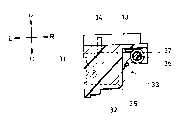
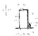
此外,图44到52表示了根据本发明的电池组的实施例。在对图44到图52的说明中,电池组201包括:一矩形形状的电池壳202;一容纳在电池壳202中的电池单元203;一衬底205,在该衬底上安装了用于计算和存储电池组201剩余电量的IC芯片204;以及一电池接线端206,其与衬底205相连接,并在纵向上从电池壳的一端面(前端面)外露(参见图47)。In addition, FIGS. 44 to 52 show embodiments of the battery pack according to the present invention. In the description of FIGS. 44 to 52, the
另外,各个附图中所示的U方向、D方向、L方向、R方向、F方向以及B方向分别指代向上方向、向下方向、向左方向、向右方向、向前方向和向后方向。另外,是为了方便起见而采用了本说明书中的上述方向定义,根据电池组201的使用状态,可适当地改变此定向性。In addition, the U direction, the D direction, the L direction, the R direction, the F direction, and the B direction shown in each drawing refer to an upward direction, a downward direction, a leftward direction, a rightward direction, a forward direction, and a backward direction, respectively. direction. In addition, the above-mentioned orientation definition in this specification is adopted for the sake of convenience, and this orientation can be appropriately changed according to the use state of the
电池壳202是由一上壳207和一下壳208构成的,并制有一矩形切槽209,其位于下壳208的前端面上,且其开口位置从左右方向的中间位置向左偏移,该切槽从该位置与下壳前端部的下表面连为一体,上述电池接线端206从上方滑入到该矩形切槽209中,并固定于此,连接到矩形切槽209中的电池接线端的前表面基本上与下壳208平齐(参见图48)。The
此外,下壳208右侧面的下角部被制成截面为L形的切去部分,并在纵向上沿该切边部分的整个长度形成了防错装槽(erroneous loading preventiongroove)210。结果,在与防错装槽210相对应的区域内,下壳208的内部空间内形成了一个台阶状区别部分,其上半部分的左右宽度略大于其下半部分的宽度,上述上壳207的宽度被制成与下壳上半部分的左右宽度相同(参见图51)。In addition, the lower corner portion of the right side of the
电池单元203是由一电池筒211、一电池盖212以及一电池元件(图中未示出)等构成的;电池筒211的尺寸小于上述的电池壳202,且其一纵向端面是开口的;电池盖212连接到所述开口,以将该开口封住;电池元件容纳在电池筒211中。The
此外,电池单元203的左右宽度略小于其下半部分的左右宽度,从而,当电池单元203安装到电池壳202中时,就在电池壳202右侧面的上方处形成了一个空间213(下文将其称为“负极侧搭片设置空间”)(参见图51)。In addition, the left-right width of the
在电池盖212上设置一正极侧搭片214,且通过在上述衬底205左侧上的焊盘孔205a对正极侧搭片214进行焊接(参见图46)。A positive
负极侧搭片215的一端被焊接到电池筒211的筒底211a上,而负极侧搭片215的另一端则向上述电池盖22的前表面一侧延伸,并穿过衬底205右侧上的一焊盘孔205b,而后被焊接(参见图46和47)。One end of the
具体来讲,负极侧搭片215被一PTC(正温度系数)层218分成了两个部分:一筒底侧搭片216和一电池盖侧搭片217,PTC层218设置在筒底侧搭片216和电池盖侧搭片217之间(参见图46)。结果:当电池单元203的温度达到预定值时,筒底侧搭片216与电池盖侧搭片217之间的电连接就被切断了。Specifically, the
此外,在负极侧搭片215的延伸部位与电池筒211之间设置了一绝缘片219,从而在电池筒211与负极侧搭片215、尤其是电池盖侧搭片217之间实现了绝缘(参见图46和47)。In addition, an insulating
另外,负极侧搭片215上延伸到衬底的各部分(筒底侧搭片216、PTC层218、电池盖侧搭片217)位于电池单元203右侧面的上半部分内,因而,筒底侧搭片216、PTC层218、电池盖侧搭片217这些部分就位于上述的负极侧搭片设置空间213中(参见图51)。In addition, each part extending to the substrate on the negative electrode side strap 215 (the tube
此外,尽管在图中未表示出,但可利用超声焊接的方法将上壳207与下壳208的外周边缘焊接成相互结合的状态,从而将上壳207与下壳208对接到一起,由此覆盖电池单元203。与此同时,也可以用粘接剂、而非超声焊接来进行连接。In addition, although it is not shown in the figure, the outer peripheral edges of the
因而,通过将电池单元203包容在电池壳202中就能组装出电池组201,在该电池组中,电池接线端206被制在前端面上,并在右侧面的下角部分形成了横截面为L形的防错装槽210(参见图44)。Thus, by housing the
下面将对带有电池装入部分的电子设备进行描述,上述的电池组201装入到电池装入部分中。与此同时,任何形式的电子设备都可以适用,例如数码相机、摄像机、个人计算机等。本发明总体上适用于被称为移动设备和便携设备的、由电池驱动的任何电子设备。The following will describe an electronic device with a battery housing portion into which the above-mentioned
电子设备300上设置有一壳体301,其具有一容纳空间,该空间的尺寸基本上与上述电池组201的尺寸相同,并在向后的方向上具有一开孔,在该背面开孔的边缘上设置了一个锁止构件310,用于防止装入的电池组201从上述壳体301的内部中脱出,壳体301的内部作为一电池装入部分302(参见图44)。The
在壳体301的电池装入部分302的内端面(前端面)上,设置了一主体侧接线端303,其与上述电池组201上的电池接线端206相对应(参见图44)。On the inner end face (front face) of the
在壳体301背面开孔的右下部分,设置了一个阻卡突起部分304,其被制成大致等于或略小于上述电池组201上防错装槽210的横截面结构(参见图49、50和51)。At the lower right part of the opening on the back of the
这样,当电池组201按照正常定向装入电池装入部分302中时,上述的阻卡突起部分304就会位于电池组201的防错装槽210中,由此允许电池组201滑插到电池装入部分302中(参见图51和52A)。In this way, when the
锁止构件310是由一锁止杆311和一促动装置312构成的,当从俯视的角度观察时,锁止杆311的形状为L状,促动装置312用于将锁止杆311顶向锁定方向(参见图49和50)。The locking
具体来讲,锁止杆311包括一长臂件311a和一短臂件311b,其中的长臂件是壳体301右侧面的开口端的一部分,而短臂件则从锁止杆的后端向左伸出,长臂件311a的前端部通过一转轴可转动地支撑在壳体301上,转轴在上下方向延伸(参见图49和50)。Specifically, the locking
可将一金属片构件弯折成U型而形成上述的促动装置312,且促动装置312的一个部件固定到上述壳体301一侧的构件上,而另一部件则与上述锁止杆311的长臂件311a的右表面弹性地接触,结果:在图49和50中的顺时针方向上促使锁止杆转动。A sheet metal member can be bent into a U shape to form the above-mentioned
此外,被促动而转动的锁止杆311被一转动阻挡装置(图中未示出)阻挡而不再发生转动,在被阻卡的状态下,锁止杆311的短臂件311b覆盖壳体301的背面开孔的一部分(参见图50)。In addition, the locking
因而,为了将电池组201装入到电子设备300的电池装入部分302中,需要克服促动装置312的作用使上述锁止杆311在图中的逆时针方向上转动,从而使短臂件311b避开电池装入部分302的背面开孔(参见图49),然后将电池组201滑插入到电池装入部分302中。Therefore, in order to pack the
如上所述,此时,在电池组201处于常规方位,即防错装槽210位于右下角的情况下(参见图52A),上述的阻卡突起部分304位于防错装槽210中,从而允许电池组201滑动插入。另外,当电池组滑动到电池装入部分302的底端时,电池接线端206与主体侧接线端303连接,且锁止杆311在顺时针方向上转动,使得其短臂件311b被电池组201的后端面锁住,从而防止电池组201从电池装入部分中脱出(参见图50)。As mentioned above, at this time, when the
另外,当电池组201未处于常规方位时,上述电池装入部分302的阻卡部分304与电池组201发生干涉,从而阻止电池组的插入(参见图52B、52C、52D)。In addition, when the
也就是说,例如,当电池组201的前后方向定位正确、但上下颠倒时(参见图52B),由于在电池组201的右下角部位未设置防错装槽210,所以电池装入部分302的阻卡突起部分304将与该右下角部分干涉,因而,不可能将电池组201插入到电池装入部分302中。That is to say, for example, when the front and rear directions of the
另外,在电池组201的上下方向定位正确、但前后方向却颠倒的情况下(参见图52C),或者上下方向和前后方向的定位都颠倒的情况下(参见图52D),由于防错装槽210并不位于电池组201的右下角处,所以电池装入部分302的阻卡突起部分304将与该右下角部分干涉,因而,不可能将电池组201插入到电池装入部分302中。In addition, when the vertical direction of the
以这样的方式,当电池组201未处于常规方位时,由于电池组201被覆盖电池装入部分302背面开孔的一部分的阻卡突起部分304所阻挡,所以不能将电池组201插入到电池装入部分302中,即使是很略微的插入也是不可能的,这就立即能提示使用者:将要装入的电池组201的方位错误。结果是:即使电池组201能被略微地插入到电池装入部分302中,也能防止使用者在电池组定向不正确的情况下将电池组强行装入。In this way, when the
另外,在与上述实施例相关的电池组201中,所说明的是将方棒状的电池单元203装入方箱状的电池壳202,但本发明并不仅限于此,这就意味着:可在方棒形的电池壳202中装入圆柱状的电池单元。简言之,只要电池壳的形状近似为方棒状,即就可应用本发明。In addition, in the
另外,在对于与上述实施例相关的电池组201中,防错装槽210被制成在滑动方向上沿电池壳202的全长设置,但本发明并不局限于此,这就意味着:可将防错装槽制成延伸到插入一侧的端面,但在滑动方向上的长度不一定为电池壳的全长。在此情况下,当电池组被错误地装入时,位于电子设备一侧的阻卡突起部分能防止沿指向电池装入部分302底端部的方向插入电池。In addition, in the
另外,在对于与上述实施例相关的电池组201中,所说明的是将防错装槽210制在电池壳202的角部分处,但本发明并不局限于此,这就意味着:可将防错装槽210制在电池壳201的侧面上。按照这样的方式,通过在某个位置处制出防错装槽210,则即使所要装入的电池组既上下颠倒、也前后颠倒,也能防止将电池组错误地装入,其中的位置是指:从要在其上制出防错装槽的侧面的中心宽度位置向一端部侧偏移的位置。In addition, in the
从上文的描述可以看出,根据本发明的电池组如此设置:其通过滑向具有电池装入部分的电子设备而装入该电子设备,该电池组的特征在于:其具有大致为方棒状的电池壳,并在滑动方向上的一个端面上设置了电池接线端,并在电池壳一侧面的一部分上制出一沿滑动方向延伸的防错装槽,其中的侧面是除滑动方向上两端面之外的其它表面。As can be seen from the above description, the battery pack according to the present invention is configured such that it is loaded into an electronic device having a battery loading portion by being slid toward the electronic device, and is characterized in that it has a substantially square bar-shaped The battery shell is provided with a battery terminal on one end face in the sliding direction, and an anti-mistake slot extending along the sliding direction is made on a part of the side of the battery shell. Surfaces other than end faces.
因而,根据本发明的电池组,由于从滑动方向观察时在多个位置点处是非对称的,因而,利用该特征就可以限定在电子设备一侧相对电池装入部分的唯一方位。Thus, according to the battery pack of the present invention, since it is asymmetrical at a plurality of positions as viewed from the sliding direction, it is possible to define a unique orientation on the electronic equipment side with respect to the battery housing portion by utilizing this feature.
结果,当电池组处于与该常规方位不同的方位时,其不能插入到电池装入部分,从而防止电池组被错误地装入。As a result, when the battery pack is in an orientation different from the normal orientation, it cannot be inserted into the battery loading portion, thereby preventing the battery pack from being wrongly loaded.
此外,由于电池接线端在处于正常定位的情况下装入电池装入部分,所以可防止电子设备一侧的接线端与电池组一侧的接线端错误地彼此接触而带来的问题。In addition, since the battery terminals are incorporated into the battery loading portion in a normal position, problems caused by the terminals on the electronic equipment side and the terminals on the battery pack side erroneously contacting each other can be prevented.
另外,在本发明中,由于装在电池壳中的电池单元的结构被设计成方棒状,所以对于方形的电池壳来说,没有空间被浪费,因而不论总尺寸如何,都能使电池组具有很大的容量。In addition, in the present invention, since the structure of the battery cells housed in the battery case is designed in the shape of a square bar, no space is wasted for the square battery case, thereby enabling the battery pack to have Great capacity.
在本发明中,由于上述防错装槽被沿电池壳的滑动方向制在角部分处,因而可在电池壳和电池单元之间形成预定的空间,且该空间可用来布置环绕电池单元延伸的负极侧搭片,从而提高空间利用率。In the present invention, since the above-mentioned mistake-preventing groove is formed at the corner portion along the sliding direction of the battery case, a predetermined space can be formed between the battery case and the battery unit, and the space can be used to arrange the battery extending around the battery unit. The negative electrode side is tapped to improve space utilization.
在本发明中,由于从电池单元的电池筒底部延伸出的负极侧搭片被设置在侧面上,且在该侧面上制有防错装槽,搭片避开了防错装槽,所以没有空间浪费,因而不论总尺寸如何,都能使电池组具有很大的容量。In the present invention, since the negative electrode side strap extending from the bottom of the battery canister of the battery unit is arranged on the side, and the side is shaped with an anti-wrong installation groove, the strap avoids the error-proof installation groove, so there is no Space is wasted, thus enabling a battery pack with a high capacity regardless of the overall size.
在本发明中,由于从电池单元的筒底延伸到电池单元顶盖一侧的负极侧搭片被分成筒底侧搭片和电池单元顶盖侧搭片,并在筒底侧搭片和电池单元顶盖侧搭片之间设置了一PTC层,PTC层可被宽松地设置在电池壳中,而不会受到挤压,因而可提高电池组的安全性。In the present invention, since the negative side tab extending from the bottom of the battery cell to the top cover of the battery cell is divided into the bottom side tab and the battery cell top cover side tab, and the tab on the bottom side of the tube and the battery cell A PTC layer is arranged between the side flaps of the unit top cover, and the PTC layer can be loosely arranged in the battery case without being squeezed, thereby improving the safety of the battery pack.
上述实施例中各个部分的具体结构和形式仅是作为本发明实施方式的示例,因而,本发明技术保护范围的理解不应受这些具体实施例的限定。The specific structure and form of each part in the above-mentioned embodiments are only examples of the implementation of the present invention, therefore, the understanding of the technical protection scope of the present invention should not be limited by these specific embodiments.
附图标记说明Explanation of reference signs
1……摄像机(主体侧设备)1...camera (device on the main body side)
17……悬垂部分(锁止部分)17...Dangling part (locking part)
17a……切槽部分17a...grooving part
18……阻卡突出条18...Protruding bar for blocking card
19……阻卡部分19... Blocking part
30……主体侧接线端30... Main body side terminal
40……锁止机构40...lock mechanism
100、201……电池组100, 201... battery pack
111……区别标签111...Different labels
120……电池侧接线端120……Battery side terminals
202……电池壳202......Battery case
203……电池单元203……battery unit
206……电池接线端206......Battery terminal
210……防错装槽210......Mistake-proof loading slot
211……电池单元筒211......Battery unit barrel
211a……筒底211a... Bottom of cylinder
212……电池单元顶盖212……Battery unit top cover
215……负极侧搭片215...Negative side strap
216……筒底侧搭片216......Cylinder bottom side strap
217……电池单元顶盖侧搭片217...The side strap of the battery unit top cover
218……PTC218……PTC
300……电子设备300...Electronic equipment
302……电池装载部分302……Battery loading part
Claims (5)
Translated fromChineseApplications Claiming Priority (6)
| Application Number | Priority Date | Filing Date | Title |
|---|---|---|---|
| JP222951/01 | 2001-07-24 | ||
| JP2001222951AJP3925120B2 (en) | 2001-07-24 | 2001-07-24 | Method for preventing erroneous mounting of mounting parts on main body side equipment and mounting parts used therefor |
| JP222951/2001 | 2001-07-24 | ||
| JP263672/2001 | 2001-08-31 | ||
| JP263672/01 | 2001-08-31 | ||
| JP2001263672AJP3888105B2 (en) | 2001-08-31 | 2001-08-31 | battery pack |
Related Parent Applications (1)
| Application Number | Title | Priority Date | Filing Date |
|---|---|---|---|
| CNB028029313ADivisionCN1276525C (en) | 2001-07-24 | 2002-07-24 | Method, device to be installed, and battery pack for preventing device to be installed from being mistakenly loaded into device on main body side |
Related Child Applications (1)
| Application Number | Title | Priority Date | Filing Date |
|---|---|---|---|
| CN200610094369.9ADivisionCN1901250B (en) | 2001-07-24 | 2002-07-24 | Battery pack for preventing erroneous loading of component-to-be-loaded on main body side apparatus |
Publications (2)
| Publication Number | Publication Date |
|---|---|
| CN1670984A CN1670984A (en) | 2005-09-21 |
| CN100391030Ctrue CN100391030C (en) | 2008-05-28 |
Family
ID=26619170
Family Applications (2)
| Application Number | Title | Priority Date | Filing Date |
|---|---|---|---|
| CNB2005100529586AExpired - LifetimeCN100391030C (en) | 2001-07-24 | 2002-07-24 | Battery pack for preventing erroneous mounting of device to be mounted in main body side apparatus |
| CNB028029313AExpired - Fee RelatedCN1276525C (en) | 2001-07-24 | 2002-07-24 | Method, device to be installed, and battery pack for preventing device to be installed from being mistakenly loaded into device on main body side |
Family Applications After (1)
| Application Number | Title | Priority Date | Filing Date |
|---|---|---|---|
| CNB028029313AExpired - Fee RelatedCN1276525C (en) | 2001-07-24 | 2002-07-24 | Method, device to be installed, and battery pack for preventing device to be installed from being mistakenly loaded into device on main body side |
Country Status (6)
| Country | Link |
|---|---|
| US (14) | US7223494B2 (en) |
| EP (1) | EP1411564B1 (en) |
| KR (2) | KR100919332B1 (en) |
| CN (2) | CN100391030C (en) |
| DE (1) | DE60234602D1 (en) |
| WO (1) | WO2003010839A1 (en) |
Families Citing this family (82)
| Publication number | Priority date | Publication date | Assignee | Title |
|---|---|---|---|---|
| JP2005165545A (en)* | 2003-12-01 | 2005-06-23 | Sony Corp | Electronic equipment and battery pack |
| JP4123515B2 (en)* | 2003-12-26 | 2008-07-23 | ソニー株式会社 | Battery device |
| JP4123517B2 (en) | 2003-12-26 | 2008-07-23 | ソニー株式会社 | Battery device |
| JP4123516B2 (en)* | 2003-12-26 | 2008-07-23 | ソニー株式会社 | Battery device |
| JP3805781B2 (en)* | 2004-11-26 | 2006-08-09 | 株式会社ソニー・コンピュータエンタテインメント | Battery pack and electronic device using the same |
| RU2296391C2 (en)* | 2004-09-21 | 2007-03-27 | Сони Компьютер Энтертайнмент Инк. | Battery unit and relevant electronic device |
| KR100624969B1 (en)* | 2004-10-18 | 2006-09-15 | 삼성에스디아이 주식회사 | Battery Pack with Short Protection |
| EP1843412B1 (en)* | 2004-12-28 | 2016-09-14 | Sony Corporation | Battery loading/unloading mechanism |
| US9136507B2 (en)* | 2005-03-24 | 2015-09-15 | Samsung Sdi Co., Ltd. | Can and lithium secondary battery using the same |
| CA112023S (en)* | 2005-07-22 | 2006-08-09 | 4121856 Canada Inc | Battery |
| JP4725317B2 (en)* | 2005-12-26 | 2011-07-13 | ソニー株式会社 | Electronics |
| JP4245017B2 (en) | 2006-08-28 | 2009-03-25 | ソニー株式会社 | Battery device, electronic device and battery system |
| US11196121B2 (en) | 2006-08-28 | 2021-12-07 | Sony Corporation | Battery device, electronic apparatus, and battery system |
| JP2008053154A (en)* | 2006-08-28 | 2008-03-06 | Sony Corp | Battery device, electronic device, and battery system |
| JP5179746B2 (en)* | 2006-11-22 | 2013-04-10 | 京セラ株式会社 | Mobile terminal device |
| KR100876267B1 (en)* | 2007-10-04 | 2008-12-26 | 삼성에스디아이 주식회사 | Secondary battery |
| EP2223365B1 (en)* | 2007-12-25 | 2015-10-21 | BYD Company Limited | Electrochemical storage cell with blow out vents |
| TWI399879B (en)* | 2008-03-28 | 2013-06-21 | Fih Hong Kong Ltd | Battery cover and electronic device using the same |
| CN101577743A (en)* | 2008-05-09 | 2009-11-11 | 深圳富泰宏精密工业有限公司 | Battery fixing device |
| KR101002511B1 (en)* | 2008-09-19 | 2010-12-17 | 삼성에스디아이 주식회사 | Polymer battery pack |
| CN101728494B (en)* | 2008-10-13 | 2013-03-13 | 深圳富泰宏精密工业有限公司 | Locking mechanism of battery cover |
| CN101752520A (en)* | 2008-11-28 | 2010-06-23 | 深圳富泰宏精密工业有限公司 | Battery cover clamping and locking structure |
| DE202009018505U1 (en)* | 2008-12-01 | 2011-11-17 | Sennheiser Electronic Gmbh & Co. Kg | Accumulator unit and portable electronic device |
| JP5404085B2 (en)* | 2009-02-12 | 2014-01-29 | キヤノン株式会社 | Electronics |
| US8096825B2 (en)* | 2009-03-25 | 2012-01-17 | Belkin International Inc. | Electrical coupler system and method for manufacture thereof |
| US7867019B1 (en)* | 2009-07-17 | 2011-01-11 | Fluke Corporation | Thermal imaging device with a battery pack with a shock absorber |
| USD660787S1 (en) | 2010-02-10 | 2012-05-29 | Kangaroo Media, Inc. | Battery |
| JP3160044U (en)* | 2010-03-29 | 2010-06-10 | ソニー株式会社 | Power supply device |
| US8048552B1 (en)* | 2010-04-23 | 2011-11-01 | Psion Inc. | Battery module mount |
| JP2011233410A (en)* | 2010-04-28 | 2011-11-17 | Makita Corp | Electric equipment system and adapter used for the same |
| KR101296964B1 (en)* | 2011-02-10 | 2013-08-14 | 삼성에스디아이 주식회사 | Battery pack |
| US20120285662A1 (en)* | 2011-05-10 | 2012-11-15 | Celsia Technologies Taiwan, I | Vapor chamber with improved sealed opening |
| CN102882303B (en)* | 2011-07-12 | 2017-10-24 | 德昌电机(深圳)有限公司 | Motor end cover component |
| KR20130090096A (en)* | 2012-02-03 | 2013-08-13 | 삼성에스디아이 주식회사 | Battery pack |
| US9085342B2 (en)* | 2012-03-03 | 2015-07-21 | Dr. Nathan Jauvtis Engineering | Power assisted vehicle |
| US9434445B1 (en)* | 2012-03-03 | 2016-09-06 | Dr. Nathan Jauvtis Engineering | Electronic bicycle |
| USD682778S1 (en)* | 2012-10-10 | 2013-05-21 | Woodman Labs, Inc. | Battery |
| USD725032S1 (en)* | 2012-10-29 | 2015-03-24 | Johnson Controls Technology Company | Battery maintainer |
| USD725033S1 (en)* | 2012-10-29 | 2015-03-24 | Johnson Controls Technology Company | Battery maintainer and mount |
| USD772804S1 (en)* | 2013-09-05 | 2016-11-29 | Sony Corporation | Rechargeable battery |
| KR101637891B1 (en)* | 2013-09-05 | 2016-07-08 | 주식회사 엘지화학 | Prismatic Battery Cell Having Battery Case Comprising Two or More Members |
| DE102013110002A1 (en) | 2013-09-11 | 2015-03-12 | Constin Gmbh | Container for a hand-portable, rechargeable DC power storage device |
| USD725590S1 (en) | 2014-07-11 | 2015-03-31 | Gopro, Inc. | Battery |
| DE102014216435A1 (en) | 2014-08-19 | 2016-02-25 | Volkswagen Varta Microbattery Forschungsgesellschaft Mbh & Co. Kg | Battery with prismatic housing and manufacturing process |
| KR102463893B1 (en) | 2015-04-03 | 2022-11-04 | 삼성전자주식회사 | Hardmask composition and method of forming patterning using the hardmask composition |
| KR102080284B1 (en)* | 2015-10-22 | 2020-02-21 | 주식회사 엘지화학 | Pouch-typed Battery Cell Including Unit Electrodes Having Plurality of Electrode Tabs |
| USD830446S1 (en) | 2015-12-15 | 2018-10-09 | Gopro, Inc. | Multi-lens camera |
| EP3403159B1 (en)* | 2016-01-16 | 2019-11-27 | Aliaksandr Alsheuski | Securely mounting electronic device battery pack |
| EP3442667B1 (en) | 2016-04-15 | 2025-03-05 | Scott Technologies, Inc. | Facemask nosecup retained by voicemitters |
| US20180048791A1 (en)* | 2016-08-10 | 2018-02-15 | Aaron Johnson | Image Reflecting and Capturing Assembly |
| CN107799681B (en)* | 2016-09-01 | 2022-07-12 | 康塔有限公司 | Rechargeable battery pack |
| USD791695S1 (en) | 2017-01-20 | 2017-07-11 | Gopro, Inc. | Battery |
| JP6191795B1 (en) | 2017-02-10 | 2017-09-06 | ソニー株式会社 | Battery and connected equipment |
| JP6191796B1 (en) | 2017-02-10 | 2017-09-06 | ソニー株式会社 | Battery and connected equipment |
| USD861592S1 (en) | 2017-09-28 | 2019-10-01 | Gopro, Inc. | Battery |
| USD940066S1 (en) | 2017-09-28 | 2022-01-04 | Gopro, Inc. | Battery |
| WO2019073949A1 (en)* | 2017-10-10 | 2019-04-18 | マクセルホールディングス株式会社 | Battery mounting unit, electric device, and power supply unit |
| TWI663462B (en) | 2017-10-18 | 2019-06-21 | 大陽科技股份有限公司 | Lens driving apparatus, photographing module and electronic device |
| USD890835S1 (en) | 2017-12-28 | 2020-07-21 | Gopro, Inc. | Camera |
| USD907680S1 (en) | 2018-08-31 | 2021-01-12 | Gopro, Inc. | Camera |
| USD907101S1 (en) | 2019-06-11 | 2021-01-05 | Gopro, Inc. | Camera |
| USD903740S1 (en) | 2018-09-14 | 2020-12-01 | Gopro, Inc. | Camera |
| KR102162876B1 (en) | 2019-02-01 | 2020-10-07 | 젠 주식회사 | Battery pack for camera |
| WO2020210587A1 (en) | 2019-04-10 | 2020-10-15 | Jetcool Technologies, Inc. | Thermal management of electronics using co-located microjet nozzles and electronic elements |
| USD1029745S1 (en) | 2019-09-13 | 2024-06-04 | Gopro, Inc. | Camera battery |
| USD920419S1 (en) | 2019-09-17 | 2021-05-25 | Gopro, Inc. | Camera |
| US12066748B2 (en) | 2019-09-18 | 2024-08-20 | Gopro, Inc. | Door assemblies for image capture devices |
| DE212020000722U1 (en) | 2019-09-18 | 2022-04-26 | Gopro, Inc. | door assemblies for imaging devices |
| DE102020100033A1 (en)* | 2020-01-03 | 2021-07-08 | Sennheiser Electronic Gmbh & Co. Kg | Exchangeable accumulator unit and battery compartment |
| TWI743756B (en)* | 2020-04-24 | 2021-10-21 | 緯創資通股份有限公司 | Battery assembly and electronic device having the same |
| WO2022000417A1 (en) | 2020-07-02 | 2022-01-06 | Gopro, Inc. | Removable battery door assemblies for image capture devices |
| USD1029746S1 (en) | 2020-07-31 | 2024-06-04 | Gopro, Inc. | Battery |
| USD1050227S1 (en) | 2020-08-14 | 2024-11-05 | Gopro, Inc. | Camera door |
| USD946074S1 (en) | 2020-08-14 | 2022-03-15 | Gopro, Inc. | Camera |
| US12289871B2 (en) | 2020-09-15 | 2025-04-29 | Jetcool Technologies Inc. | High temperature electronic device thermal management system |
| USD1066462S1 (en) | 2021-02-12 | 2025-03-11 | Gopro, Inc. | Camera door |
| US12048118B2 (en) | 2021-08-13 | 2024-07-23 | Jetcool Technologies Inc. | Flow-through, hot-spot-targeting immersion cooling assembly |
| KR102654179B1 (en) | 2021-10-15 | 2024-04-03 | 주식회사 젠트리 | Connection structure of V-mount battery and main body device |
| US12289861B2 (en) | 2021-11-12 | 2025-04-29 | Jetcool Technologies Inc. | Liquid-in-liquid cooling system for electronic components |
| TW202407925A (en)* | 2022-03-04 | 2024-02-16 | 美商捷控技術有限公司 | Actively cooled heat-dissipation lids for computer processors and processor assemblies |
| USD1061682S1 (en) | 2022-08-04 | 2025-02-11 | Gopro, Inc. | Camera door |
| US12321084B2 (en) | 2022-08-12 | 2025-06-03 | Gopro, Inc. | Interconnect mechanism for image capture device |
Citations (2)
| Publication number | Priority date | Publication date | Assignee | Title |
|---|---|---|---|---|
| JPH06132022A (en)* | 1987-01-27 | 1994-05-13 | Sony Corp | Electric power source case |
| CN1268776A (en)* | 1999-02-17 | 2000-10-04 | 索尼公司 | Battery assembly, battery carrying device, electric power supply equipment and electronic equipment |
Family Cites Families (74)
| Publication number | Priority date | Publication date | Assignee | Title |
|---|---|---|---|---|
| IT1098828B (en) | 1978-09-01 | 1985-09-18 | Montedison Spa | POLYOLEFINS REINFORCED WITH GLASS FIBERS |
| JPS6051869B2 (en) | 1980-07-03 | 1985-11-15 | マツダ株式会社 | Color matching easy painting method |
| JPS5956831A (en) | 1982-09-22 | 1984-04-02 | 株式会社日立製作所 | Battery charging circuit |
| JPS6051869A (en) | 1983-08-31 | 1985-03-23 | Fuji Xerox Co Ltd | Cleaning blade of roll fixing device |
| JPS60110527U (en) | 1983-12-29 | 1985-07-26 | ワイケイケイ株式会社 | Emergency access handrail |
| JPS624066A (en) | 1985-06-19 | 1987-01-10 | 積水化学工業株式会社 | Thin-film made of colored thermoplastic resin |
| JPS63316641A (en)* | 1987-06-19 | 1988-12-23 | Matsushita Electric Works Ltd | Charging equipment |
| JP2650685B2 (en) | 1987-07-31 | 1997-09-03 | 松下電器産業株式会社 | Battery pack |
| JPS6435854U (en) | 1987-08-28 | 1989-03-03 | ||
| JPH01146456A (en) | 1987-12-02 | 1989-06-08 | Puro Shiyuumaa Kk | Terminal equipment in computer communication |
| JPH01302240A (en)* | 1988-05-30 | 1989-12-06 | Fuji Photo Film Co Ltd | Battery holding device |
| JP2971893B2 (en) | 1989-07-28 | 1999-11-08 | 旭光学工業株式会社 | Battery assembly device |
| JP2578218B2 (en) | 1989-09-30 | 1997-02-05 | 積水化学工業株式会社 | Resin composition for toner and toner |
| US5436088A (en) | 1994-05-02 | 1995-07-25 | Motorola, Inc. | Battery cradle |
| JPH0813169B2 (en) | 1990-12-01 | 1996-02-07 | 三洋電機株式会社 | Charging device and charging method |
| EP0572571B1 (en) | 1991-02-27 | 2003-12-03 | Roche Diagnostics Corporation | Apparatus and method for analyzing body fluids |
| JP3263855B2 (en)* | 1992-03-06 | 2002-03-11 | ソニー株式会社 | battery pack |
| US5180644A (en) | 1992-03-09 | 1993-01-19 | Motorola, Inc. | Weldless battery pack |
| JP3318772B2 (en) | 1992-04-15 | 2002-08-26 | ソニー株式会社 | Secondary battery pack and method of manufacturing the same |
| JP3416962B2 (en)* | 1992-09-18 | 2003-06-16 | ソニー株式会社 | battery pack |
| TW243558B (en)* | 1993-03-23 | 1995-03-21 | Whitaker Corp | |
| GB2317062B (en) | 1993-08-10 | 1998-04-22 | Whitaker Corp | Extended height connector for a battery |
| JP3637625B2 (en)* | 1994-04-08 | 2005-04-13 | ソニー株式会社 | Battery device and electronic device to which this battery device is mounted |
| US5626979A (en) | 1994-04-08 | 1997-05-06 | Sony Corporation | Battery device and electronic equipment employing the battery device as power source |
| JPH07335187A (en)* | 1994-06-09 | 1995-12-22 | Sony Corp | Battery pack mounting mechanism |
| JP2711223B2 (en) | 1994-07-29 | 1998-02-10 | インターナショナル・ビジネス・マシーンズ・コーポレイション | Battery pack and its connection structure |
| JPH0850891A (en)* | 1994-08-08 | 1996-02-20 | Fuji Elelctrochem Co Ltd | Thin electrochemical device |
| JP3627260B2 (en)* | 1994-09-02 | 2005-03-09 | ソニー株式会社 | Battery device and apparatus for mounting the battery device |
| US5795181A (en) | 1995-01-24 | 1998-08-18 | The Whitaker Corporation | Connector on a battery |
| JP3652410B2 (en) | 1995-07-12 | 2005-05-25 | 東芝電池株式会社 | Battery pack |
| JP3505286B2 (en) | 1995-08-11 | 2004-03-08 | 三洋電機株式会社 | Battery pack |
| JPH09271144A (en) | 1996-01-29 | 1997-10-14 | Sony Corp | Power supply identifying method, battery pack, and electronic device |
| US5717314A (en)* | 1996-09-12 | 1998-02-10 | Ericsson Inc. | Apparatus and method of monitoring battery temperature during charging |
| KR19980016058U (en)* | 1996-09-14 | 1998-06-25 | 김광호 | Portable computer device |
| JP3530332B2 (en) | 1997-01-23 | 2004-05-24 | 三洋電機株式会社 | Charging device |
| US5883787A (en) | 1997-04-10 | 1999-03-16 | Ericsson, Inc. | Floating guided connector and method |
| JP3490590B2 (en) | 1997-05-29 | 2004-01-26 | 富士通株式会社 | Battery lock mechanism for portable device |
| US6095839A (en)* | 1997-06-16 | 2000-08-01 | The Whitaker Corporation | Electrical connector |
| USD400496S (en)* | 1998-01-21 | 1998-11-03 | Motorola, Inc. | Battery apparatus |
| US6127063A (en) | 1998-01-26 | 2000-10-03 | Physio-Control Manufacturing Corporation | Intelligent battery and well interface |
| US6110618A (en)* | 1998-02-27 | 2000-08-29 | Motorola, Inc. | Battery cell housing |
| US6261715B1 (en) | 1998-03-12 | 2001-07-17 | International Business Machines Corp. | Battery attaching mechanism for portable computers |
| KR100413026B1 (en) | 1998-04-30 | 2004-03-22 | 삼성전자주식회사 | A connector assembly |
| USD411165S (en)* | 1998-05-14 | 1999-06-22 | Motorola, Inc. | Battery pack |
| US6157545A (en) | 1998-05-14 | 2000-12-05 | Motorola, Inc. | Battery connection apparatus with end projections |
| USD535253S1 (en) | 1998-06-17 | 2007-01-16 | Black & Decker Inc. | Battery pack terminal and housing |
| US6068946A (en) | 1998-08-02 | 2000-05-30 | Motorola, Inc. | Dual cover battery casing |
| JP2000058015A (en) | 1998-08-07 | 2000-02-25 | Mitsubishi Cable Ind Ltd | Battery pack |
| US6057608A (en) | 1998-08-13 | 2000-05-02 | Black & Decker Inc. | Cordless power tool system |
| DE69940252D1 (en)* | 1998-09-11 | 2009-02-26 | Panasonic Corp | BATTERY PACK |
| JP2000090961A (en) | 1998-09-17 | 2000-03-31 | Mitsubishi Cable Ind Ltd | Square battery and battery pack |
| US6235426B1 (en)* | 1998-09-21 | 2001-05-22 | Sanyo Electric Co., Ltd. | Nonaqueous electrolyte secondary cell wit PTC current collector tabs |
| USD439877S1 (en)* | 1998-11-01 | 2001-04-03 | Motorola, Inc. | Battery housing |
| TW395568U (en) | 1998-12-28 | 2000-06-21 | Hon Hai Prec Ind Co Ltd | Battery connector |
| JP4110656B2 (en)* | 1999-02-17 | 2008-07-02 | ソニー株式会社 | Battery pack, battery mounting device, power supply device, and electronic device |
| JP2000343341A (en)* | 1999-06-04 | 2000-12-12 | Yazaki Corp | Unit misassembly prevention structure |
| USD449577S1 (en)* | 1999-07-07 | 2001-10-23 | Mitsumi Electric Co., Ltd. | Battery case |
| EP1071147A1 (en) | 1999-07-19 | 2001-01-24 | Toshiba Battery Co., Ltd. | Battery pack |
| JP3732361B2 (en) | 1999-07-28 | 2006-01-05 | 富士通フロンテック株式会社 | Portable electronic devices |
| JP3190024B2 (en) | 1999-08-18 | 2001-07-16 | 日本テキサス・インスツルメンツ株式会社 | Battery protection device and method of manufacturing the same |
| JP2001313017A (en)* | 2000-04-28 | 2001-11-09 | Sanyo Electric Co Ltd | Packed batteries |
| CN1322050A (en)* | 2000-04-28 | 2001-11-14 | 索尼公司 | Cell assembly and signal sending system |
| USD447122S1 (en) | 2000-05-30 | 2001-08-28 | J.S.T. Mfg. Co., Ltd. | Housing for an electrical connector |
| US6291970B1 (en)* | 2000-08-10 | 2001-09-18 | Zircon Corporation | Device for reverse polarization protection for a battery |
| JP2002110287A (en) | 2000-09-14 | 2002-04-12 | Internatl Business Mach Corp <Ibm> | Battery connector structure and battery pack |
| US6677078B2 (en) | 2001-06-29 | 2004-01-13 | The Gillette Company | Battery cartridge |
| JP2003018753A (en) | 2001-07-02 | 2003-01-17 | Sony Corp | Charging device and secondary battery |
| EP1764851B1 (en) | 2001-07-25 | 2016-01-06 | Sony Corporation | Structures of terminals and component-to-be loaded |
| US6729413B2 (en) | 2001-08-24 | 2004-05-04 | Black & Decker Inc. | Power tool with battery pack ejector |
| JP3846243B2 (en)* | 2001-09-14 | 2006-11-15 | ソニー株式会社 | battery pack |
| USD477275S1 (en)* | 2002-01-14 | 2003-07-15 | Sony Corporation | Storage battery |
| USD473192S1 (en) | 2002-02-14 | 2003-04-15 | Mitsumi Electric Co., Ltd. | Electric connector |
| USD480682S1 (en)* | 2002-03-07 | 2003-10-14 | Sony Corporation | Battery |
| JP3118552U (en) | 2005-10-21 | 2006-02-02 | 有限会社スターライト | Soundproof curtain |
- 2002
- 2002-07-24CNCNB2005100529586Apatent/CN100391030C/ennot_activeExpired - Lifetime
- 2002-07-24KRKR1020087022805Apatent/KR100919332B1/ennot_activeExpired - Lifetime
- 2002-07-24EPEP02749359Apatent/EP1411564B1/ennot_activeExpired - Lifetime
- 2002-07-24USUS10/381,394patent/US7223494B2/ennot_activeExpired - Lifetime
- 2002-07-24KRKR1020037004194Apatent/KR100894793B1/ennot_activeExpired - Fee Related
- 2002-07-24DEDE60234602Tpatent/DE60234602D1/ennot_activeExpired - Lifetime
- 2002-07-24WOPCT/JP2002/007497patent/WO2003010839A1/enactiveApplication Filing
- 2002-07-24CNCNB028029313Apatent/CN1276525C/ennot_activeExpired - Fee Related
- 2006
- 2006-10-26USUS11/586,799patent/US7879481B2/ennot_activeExpired - Fee Related
- 2010
- 2010-11-05USUS12/940,227patent/US8304102B2/ennot_activeExpired - Fee Related
- 2011
- 2011-06-16USUS13/162,018patent/US8293395B2/ennot_activeExpired - Fee Related
- 2011-09-22USUS13/239,509patent/US8247106B2/ennot_activeExpired - Fee Related
- 2012
- 2012-06-15USUS13/523,982patent/US8940432B2/ennot_activeExpired - Fee Related
- 2012-07-06USUS13/542,695patent/US9118066B2/ennot_activeExpired - Fee Related
- 2013
- 2013-01-09USUS13/737,095patent/US9023512B2/ennot_activeExpired - Lifetime
- 2014
- 2014-06-02USUS14/293,021patent/US9017863B2/ennot_activeExpired - Fee Related
- 2015
- 2015-02-27USUS14/633,193patent/US9853260B2/ennot_activeExpired - Lifetime
- 2015-08-11USUS14/823,725patent/US9853261B2/ennot_activeExpired - Fee Related
- 2016
- 2016-12-23USUS15/389,492patent/US9899656B2/ennot_activeExpired - Lifetime
- 2017
- 2017-12-12USUS15/838,445patent/US10756318B2/ennot_activeExpired - Fee Related
- 2020
- 2020-07-06USUS16/921,344patent/US20200335742A1/ennot_activeAbandoned
Patent Citations (2)
| Publication number | Priority date | Publication date | Assignee | Title |
|---|---|---|---|---|
| JPH06132022A (en)* | 1987-01-27 | 1994-05-13 | Sony Corp | Electric power source case |
| CN1268776A (en)* | 1999-02-17 | 2000-10-04 | 索尼公司 | Battery assembly, battery carrying device, electric power supply equipment and electronic equipment |
Also Published As
Similar Documents
| Publication | Publication Date | Title |
|---|---|---|
| CN100391030C (en) | Battery pack for preventing erroneous mounting of device to be mounted in main body side apparatus | |
| EP1764850B1 (en) | Structures of terminals and component-to-be loaded | |
| JP4687989B2 (en) | Battery | |
| JP5806193B2 (en) | Battery pack | |
| JP4257597B2 (en) | Battery pack | |
| HK1080607B (en) | Battery pack of preventing wrong mounting of mounting component to body side equipment | |
| JP2003036837A (en) | Terminal structure and mounting parts | |
| JP2003036827A (en) | Attachment structure of mounting component |
Legal Events
| Date | Code | Title | Description |
|---|---|---|---|
| C06 | Publication | ||
| PB01 | Publication | ||
| C10 | Entry into substantive examination | ||
| SE01 | Entry into force of request for substantive examination | ||
| REG | Reference to a national code | Ref country code:HK Ref legal event code:DE Ref document number:1080607 Country of ref document:HK | |
| C14 | Grant of patent or utility model | ||
| GR01 | Patent grant | ||
| REG | Reference to a national code | Ref country code:HK Ref legal event code:GR Ref document number:1080607 Country of ref document:HK | |
| CX01 | Expiry of patent term | ||
| CX01 | Expiry of patent term | Granted publication date:20080528 |