CN100388299C - optical information reading device - Google Patents
optical information reading deviceDownload PDFInfo
- Publication number
- CN100388299C CN100388299CCNB2005100927441ACN200510092744ACN100388299CCN 100388299 CCN100388299 CCN 100388299CCN B2005100927441 ACNB2005100927441 ACN B2005100927441ACN 200510092744 ACN200510092744 ACN 200510092744ACN 100388299 CCN100388299 CCN 100388299C
- Authority
- CN
- China
- Prior art keywords
- lens
- pattern
- predetermined
- marking
- pattern forming
- Prior art date
- Legal status (The legal status is an assumption and is not a legal conclusion. Google has not performed a legal analysis and makes no representation as to the accuracy of the status listed.)
- Expired - Fee Related
Links
- 230000003287optical effectEffects0.000titleclaimsabstractdescription41
- 230000001678irradiating effectEffects0.000claimsabstractdescription58
- 239000003550markerSubstances0.000claimsabstractdescription24
- 238000003384imaging methodMethods0.000claimsdescription42
- 230000005855radiationEffects0.000claimsdescription11
- 210000001747pupilAnatomy0.000claimsdescription5
- 239000012141concentrateSubstances0.000claims2
- 238000010586diagramMethods0.000description16
- 238000005286illuminationMethods0.000description11
- 230000004048modificationEffects0.000description8
- 238000012986modificationMethods0.000description8
- 238000004891communicationMethods0.000description7
- 230000007246mechanismEffects0.000description6
- 238000001514detection methodMethods0.000description5
- 239000011521glassSubstances0.000description4
- 230000012447hatchingEffects0.000description4
- 238000000034methodMethods0.000description4
- 229920003023plasticPolymers0.000description4
- 230000015572biosynthetic processEffects0.000description3
- 230000008859changeEffects0.000description3
- 210000003128headAnatomy0.000description3
- 239000004973liquid crystal related substanceSubstances0.000description3
- 230000008569processEffects0.000description3
- 230000004044responseEffects0.000description3
- 239000012780transparent materialSubstances0.000description3
- 230000000694effectsEffects0.000description2
- 238000004519manufacturing processMethods0.000description2
- 239000000463materialSubstances0.000description2
- 239000011159matrix materialSubstances0.000description2
- 239000003086colorantSubstances0.000description1
- 230000006870functionEffects0.000description1
- 238000000059patterningMethods0.000description1
- 230000002093peripheral effectEffects0.000description1
- 230000000007visual effectEffects0.000description1
Images


Landscapes
- Image Input (AREA)
- Length Measuring Devices By Optical Means (AREA)
Abstract
Translated fromChinese
Description
Translated fromChinese与申请相关的交叉参考Cross-references relevant to the application
本申请分别基于在2004年8月19日提交的日本专利申请2004-239460,以及于2004年12月7日提交的日本专利申请2004-354217。本申请要求这两个日本专利申请的优先权,因此在这里以参考方式,引入两个专利申请的描述。This application is based on Japanese Patent Application No. 2004-239460 filed on August 19, 2004, and Japanese Patent Application No. 2004-354217 filed on December 7, 2004, respectively. This application claims the priority of these two Japanese patent applications, and the descriptions of these two patent applications are hereby incorporated by reference.
发明领域field of invention
本发明涉及用于光学读取目标的装置,其中诸如信息码的光学可读信息附于该目标上,例如,信息码为条形码或二维代码。The invention relates to a device for optically reading an object to which optically readable information such as an information code, for example a barcode or a two-dimensional code, is attached.
技术背景technical background
手持式光学信息读取器针对于读取光学可读信息码,例如条形码、二维代码、或其他类似代码。在此说明书中,目标自身或附有光学可读信息的目标统称为“目标”。Handheld optical information readers are aimed at reading optically readable information codes, such as barcodes, two-dimensional codes, or other similar codes. In this specification, an object itself or an object with optically readable information attached thereto is collectively referred to as an "object".
为了提高手持式光学信息读取器的可用性,这里提供了可以读取相距一定距离的信息码的手持式光学信息读取器。In order to improve the usability of the hand-held optical information reader, a hand-held optical information reader that can read information codes at a certain distance is provided here.
手持式光学信息读取器具有一个手持主体壳体,在其一端配有一个读取窗口。另外,该手持式光学信息读取器还具有一个光电探测器,例如CCD(电荷耦合器件)面传感器,具有成像透镜的成像光学器件、以及由一个光照器件构成的读取单元,例如LED(发光二极管)。光电探测器、成像单元、以及读取单元分别安装在主体壳体内。The handheld optical information reader has a handheld body housing with a reading window at one end. In addition, the hand-held optical information reader also has a photodetector such as a CCD (Charge Coupled Device) area sensor, imaging optics with an imaging lens, and a reading unit composed of an illumination device such as an LED (Light Emitting Device). diode). The photodetector, the imaging unit, and the reading unit are respectively installed in the main body casing.
为了使读取窗口(光电探测器)对准目标,手持式光学信息读取器通常配置有一个利用激光二极管(LD)、LED、或其他类似发光器件的标记光束辐射单元。该标记光束辐射单元用于将标记光束辐射在目标上,以指明目标上读取器的读取位置,例如光电探测器的视场(FOV)、和/或FOV的中心位置。In order to align the reading window (photodetector) to the target, the handheld optical information reader is usually equipped with a marking beam irradiation unit using a laser diode (LD), LED, or other similar light emitting devices. The marking beam irradiating unit is used to irradiate the marking beam on the target to indicate the reading position of the reader on the target, such as the field of view (FOV) of the photodetector, and/or the center position of the FOV.
此类标记光束辐射单元的一个实例公开于美国专利出版物No.6,347,163中。公开的标记光束辐射单元使用一个能够发出高可见性标记光束的LD作为光源,以及一个衍射光栅,发出的光束通过该光栅辐射在目标上,作为其上各种不同的图案。An example of such a marker beam irradiating unit is disclosed in US Patent Publication No. 6,347,163. The disclosed marker beam irradiating unit uses an LD capable of emitting a highly visible marker beam as a light source, and a diffraction grating through which the emitted beam is irradiated on a target as various patterns thereon.
具体地,如图15中说明的那样,标记光束辐射单元3位于CCD面传感器1和成像光学器件2的一端,例如顶端。如图16中说明的那样,标记光束辐射单元3由激光二极管4、位于光发射侧并与其同轴排列的准直透镜5、以及位于准直光输出侧并与其同轴排列的衍射光栅6组成。Specifically, as illustrated in FIG. 15 , the mark
在标记光束辐射单元3中,准直透镜5聚集激光二极管4发出的激光束。聚集的光束传输到衍射光栅6的全息图平面内。全息图平面使入射激光束发生衍射,使得第一级的衍射细光束和第二级的衍射细光束,作为具有预定光束图形(衍射图形)的标记光束M,从全息图平面辐射到目标R上(见图15和17)。In the marking
例如,标记光束M的衍射图形由四个L形图形元素组成,这些元素对应于CCD面传感器1的视场V的四个边角部分(见图15)。另外,标记光束M的衍射图形由一个指明视场V中心的交叉图形组成。For example, the diffraction pattern of the marker beam M consists of four L-shaped pattern elements corresponding to the four corner portions of the field of view V of the CCD area sensor 1 (see FIG. 15 ). In addition, the diffraction pattern of the marker beam M consists of a cross pattern indicating the center of the field of view V.
然而,因为衍射细光束,例如第一级的衍射细光束和第二级的衍射细光束,形成标记光束的光束图形(衍射图形),如图17中说明的那样,该衍射细光束在目标R上表现为圆点图形。也就是说,该组圆点图形在目标R上形成线性图形,这可能造成目标R上的光束图形变模糊,而且可能恶化光束图形的视觉效果。However, since the diffracted beamlets, such as the diffracted beamlets of the first order and the diffracted beamlets of the second order, form the beam pattern (diffraction pattern) of the marking beam, as illustrated in FIG. The above is shown as a dot graphic. That is to say, the group of dot patterns forms a linear pattern on the target R, which may cause the beam pattern on the target R to become blurred, and may deteriorate the visual effect of the beam pattern.
另外,在扫描一维代码,例如条形码时,带有标记光束辐射单元的光学信息读取器可以利用在水平方向上线性延伸的标记光束作为扫描条形码的照明光。In addition, when scanning a one-dimensional code such as a barcode, an optical information reader with a marking beam irradiating unit may utilize the marking beam linearly extending in the horizontal direction as illumination light for scanning the barcode.
然而,一些光学信息读取器利用带有此类衍射光栅的标记光束辐射单元,却不能利用标记光束辐射单元发出的标记光束作为照明光来扫描条形码。However, some optical information readers using a marking beam irradiating unit with such a diffraction grating cannot scan barcodes using the marking beam emitted from the marking beam irradiating unit as illumination light.
注意到,准直透镜5通常被用于作为聚集透镜,以聚集激光二极管4发出的激光束。准直透镜具有这样一个作用,其传输聚集为横截面基本上为长椭圆形状的激光束。这样可能恶化传输聚集光束的效率,造成激光束的更大损失。Note that the collimating
发明内容Contents of the invention
本发明建立在此背景上,因此本发明的光学读取装置的优选实施例能够将具有预定光束图形的标记光束清晰地辐射在目标上。The present invention is built on this background, and thus the preferred embodiment of the optical reading device of the present invention is capable of clearly irradiating a marking beam with a predetermined beam pattern on a target.
根据本发明的一个方面,提供一种光学信息读取装置。该装置包括一个具有预定读取位置的拾取单元。将该拾取单元配置为当目标的信息位于读取位置时,光学地拾取该信息。该装置包括一个标记光束辐射单元。该标记光束辐射单元包括配置为发射光束的光束源,以及安排为允许发出的光束进入其中的光束图形形成透镜。该图形形成透镜配置为根据发射的光束而照射标记光束。该标记光束具有预定光束图形,其至少由一组线性光束组成,指明拾取单元的读取位置。According to an aspect of the present invention, an optical information reading device is provided. The device includes a pick-up unit with predetermined reading positions. The pickup unit is configured to optically pick up the information of the target when the information is located at the reading position. The device includes a marking beam irradiation unit. The marking beam irradiating unit includes a beam source configured to emit a beam, and a beam pattern forming lens arranged to allow the emitted beam to enter thereinto. The pattern forming lens is configured to irradiate the marking beam according to the emitted beam. The marking beam has a predetermined beam pattern, which at least consists of a group of linear beams, indicating the reading position of the pick-up unit.
附图简述Brief description of the drawings
通过参考附图对下列实施例的描述,将使发明的其他目的和方面变得显而易见:Other objects and aspects of the invention will become apparent by describing the following embodiments with reference to the accompanying drawings:
图1为根据本发明第一实施例,示意性地说明枪形二维码读取器结构的局部横截面的侧视图;1 is a side view schematically illustrating a partial cross-section of the structure of a gun-shaped two-dimensional code reader according to a first embodiment of the present invention;
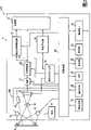
图2为根据第一实施例,示意性地说明该二维码读取器的电结构的结构图;2 is a structural diagram schematically illustrating the electrical structure of the two-dimensional code reader according to the first embodiment;
图3为根据本发明第一实施例,示意性地说明标记光束辐射器件结构的示图;3 is a diagram schematically illustrating the structure of a marking beam irradiating device according to a first embodiment of the present invention;
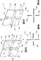
图4A为示意性地说明图3所示的标记光束辐射器件的图形形成透镜结构的俯视图;FIG. 4A is a top view schematically illustrating a pattern-forming lens structure of the marking beam irradiating device shown in FIG. 3;
图4B为示意性地说明图4A所示的图形形成透镜的局部透视图;Figure 4B is a partial perspective view schematically illustrating the pattern forming lens shown in Figure 4A;
图4C为示意性地说明图4A所示的图形形成透镜的局部透视图;Figure 4C is a partial perspective view schematically illustrating the pattern-forming lens shown in Figure 4A;
图5为示意性地说明目标上的预定标记光束图形的图形形状的示图,其中该图形由图3所示的标记光束辐射器件形成;5 is a diagram schematically illustrating a pattern shape of a predetermined mark beam pattern on a target, wherein the pattern is formed by the mark beam irradiating device shown in FIG. 3;
图6为根据本发明第二实施例,示意性地说明标记光束辐射器件结构的示图;6 is a diagram schematically illustrating the structure of a marking beam irradiating device according to a second embodiment of the present invention;
图7为根据本发明第二实施例,示意性地说明图形形成透镜的结构与激光束形状之间的关系的示图;7 is a diagram schematically illustrating the relationship between the structure of a pattern forming lens and the shape of a laser beam according to a second embodiment of the present invention;
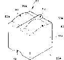
图8A为根据本发明第三实施例,示意性地说明标记光束辐射器件的图形形成透镜结构的透视图;8A is a perspective view schematically illustrating a pattern-forming lens structure of a marking beam irradiating device according to a third embodiment of the present invention;
图8B为根据本发明第三实施例,示意性地说明目标上的预定标记光束图形的图形形状的示图,其中该图形由标记光束辐射器件形成;8B is a diagram schematically illustrating a pattern shape of a predetermined mark beam pattern on a target, wherein the pattern is formed by a mark beam irradiating device, according to a third embodiment of the present invention;
图9A为根据本发明第四实施例,示意性地说明标记光束辐射器件的图形形成透镜结构的透视图;9A is a perspective view schematically illustrating a pattern forming lens structure of a marking beam irradiating device according to a fourth embodiment of the present invention;
图9B为根据本发明第四实施例,示意性地说明目标上的预定标记光束图形的图形形状的示图,其中该图形由标记光束辐射器件形成;9B is a diagram schematically illustrating a pattern shape of a predetermined mark beam pattern on a target, wherein the pattern is formed by a mark beam irradiating device, according to a fourth embodiment of the present invention;
图10为根据本发明第五实施例,示意性地说明目标上的预定标记光束图形的图形形状的示图,其中该图形由标记光束辐射器件形成;10 is a diagram schematically illustrating a pattern shape of a predetermined mark beam pattern on a target, wherein the pattern is formed by a mark beam irradiating device, according to a fifth embodiment of the present invention;
图11为根据本发明第五实施例,示意性地说明标记光束辐射器件的图形形成透镜结构的透视图;11 is a perspective view schematically illustrating a pattern forming lens structure of a marking beam irradiating device according to a fifth embodiment of the present invention;
图12A为示意性地说明形成于图11中说明的图形形成透镜的输出表面上的第一和第二透镜部分的示图;FIG. 12A is a diagram schematically illustrating first and second lens portions formed on the output surface of the pattern-forming lens illustrated in FIG. 11;
图12B为示意性地说明形成于图11中说明的图形形成透镜的入射表面上的第三透镜部分的示图;FIG. 12B is a diagram schematically illustrating a third lens portion formed on the incident surface of the pattern forming lens illustrated in FIG. 11;
图12C为根据第五实施例,沿水平方向观察,示意性地说明图11中说明的图形形成透镜的一个侧面的示图;12C is a view schematically illustrating one side of the pattern-forming lens illustrated in FIG. 11 , viewed in the horizontal direction, according to a fifth embodiment;
图12D为根据第五实施例,沿垂直方向观察,示意性地说明图11中说明的图形形成透镜的另一个侧面的示图;12D is a view schematically illustrating another side of the pattern-forming lens illustrated in FIG. 11 , viewed in the vertical direction, according to a fifth embodiment;
图13A为根据第五实施例,示意性地说明进入图形形成透镜的入射表面的部分激光束的示图;该部分激光束有效地形成标记光束,用阴影表示;13A is a diagram schematically illustrating a portion of a laser beam entering an incident surface of a pattern forming lens according to a fifth embodiment; the portion of the laser beam effectively forming a marking beam is indicated by hatching;
图13B为示意性地说明对应于十字形透镜部分的部分激光束的示图,其中该十字形透镜部分只形成于图形形成透镜的输出表面上;该部分激光束用阴影来说明;13B is a diagram schematically illustrating a portion of the laser beam corresponding to a cross-shaped lens portion formed only on the output surface of the pattern forming lens; the portion of the laser beam is illustrated by hatching;
图14为根据对本发明第一至第五实施例中的每一个的修改,示意性地说明标记光束辐射器件结构的示图;FIG. 14 is a diagram schematically illustrating a structure of a marker beam irradiating device according to a modification of each of the first to fifth embodiments of the present invention;
图15为示意性地说明常规光学信息读取器的标记光束辐射器件的设置的示图;15 is a diagram schematically illustrating the arrangement of a mark beam irradiating device of a conventional optical information reader;
图16示意性地说明图15中说明的标记光束辐射器件结构的示图;以及FIG. 16 schematically illustrates a view of the structure of the marking beam radiation device illustrated in FIG. 15; and
图17为示意性地说明目标上的预定标记光束图形的图形状态的示图,其中该图形由图16中说明的标记光束辐射器件形成。FIG. 17 is a diagram schematically illustrating a pattern state of a predetermined mark beam pattern on a target, where the pattern is formed by the mark beam irradiating device illustrated in FIG. 16 .
发明详述Detailed description of the invention
下文中将参考附图描述本发明的实施例。在实施例中,本发明应用于枪形二维码读取器。Hereinafter, embodiments of the present invention will be described with reference to the accompanying drawings. In an embodiment, the present invention is applied to a gun-shaped two-dimensional code reader.
第一实施例first embodiment
图1为根据本发明第一实施例,示意性地说明枪形二维码读取器CR的结构的局部横截面侧视图;图2为根据第一实施例,示意性地说明二维码读取器CR的电结构的结构图。Fig. 1 is a partial cross-sectional side view schematically illustrating the structure of a gun-shaped two-dimensional code reader CR according to a first embodiment of the present invention; Fig. 2 is a schematic illustration according to a first embodiment of a two-dimensional code reader Structural diagram of the electrical structure of the fetcher CR.
如图1所示,根据本发明第一实施例,作为光学读取目标的装置实例,二维码读取器CR配置有枪形外壳11。例如,枪形外壳11具有一个细长方体主体11a。主体11a的一个侧端部分为圆形。As shown in FIG. 1 , according to the first embodiment of the present invention, as an example of an apparatus for optically reading an object, a two-dimensional code reader CR is provided with a gun-shaped
枪形外壳11在主体11a的一个横向端面部分的一侧(具体地,图1中的底部),配置有把手部分11b,其向远离主体11a的方向延伸。把手部分11b与主体11a形成一体。把手部分11b让使用者可以很容易地用一只手手握二维码读取器CR进行操作。The gun-shaped
主体11a在另一个横向端面部分的侧面形成有一个读取窗口11c,其具有例如半透明的矩形形状。二维码读取器CR同时配置一个触发开关12。触发开关12配置在把手部分11b的一个侧面,指向读取窗口11c。触发开关12允许使用者对二维码读取器CR指示读取操作。The main body 11a is formed with a reading
二维码读取器CR配置有一个读取机构(光学读取机构)RM,配置在外壳11的另一个侧端部分。在第一实施例中,外壳11的另一个横向端面部分称为“头部”。The two-dimensional code reader CR is provided with a reading mechanism (optical reading mechanism) RM arranged at the other side end portion of the
读取机构RM通过打印或其他类似方法,用于读取附于目标R上的二维代码(见图2),例如QR(快速响应)代码。目标R包括目录和纸质或其他介质的标签。目标R可以附在货品上,与通用条形码相同。二维代码包括信息,例如,生产序列号、名称、唯一识别号、货品生产日期、以及互联网上的URL标志信息。The reading mechanism RM is used to read a two-dimensional code (see FIG. 2 ) attached to the object R, such as a QR (Quick Response) code, by printing or other similar methods. Objective R includes catalogs and labels for paper or other media. Target R can be attached to the goods, the same as the universal barcode. The two-dimensional code includes information such as the production serial number, name, unique identification number, production date of the product, and URL identification information on the Internet.
近年来,目标R包括显示屏,例如计算机终端的液晶显示器(LCD),例如手机或PDA(个人数码助理);二维代码显示在显示屏上。In recent years, target R includes a display screen such as a liquid crystal display (LCD) of a computer terminal such as a mobile phone or a PDA (Personal Digital Assistant); a two-dimensional code is displayed on the display screen.
例如,二维代码由不同颜色的单元组成,例如排列在矩阵中的黑色或白色单元,在其中形成特定的图形,并因此指示数据。黑色和白色其中之一对应于位值“0”和“1”其中之一,黑色和白色中的另外一个对应于位值“0”和“1”中的另外一个。在读取这些单元之后,可以容易地使读取的颜色数据数字化,对其进行解码。For example, two-dimensional codes consist of cells of different colors, such as black or white cells, arranged in a matrix, in which a specific pattern is formed and thus indicates data. One of black and white corresponds to one of the bit values "0" and "1", and the other of black and white corresponds to the other of the bit values "0" and "1". After reading these cells, the read color data can easily be digitized and decoded.
正如图1至3中示意性说明的那样,读取机构RM包括光电探测器13、构成成像光学器件的成像透镜14、以及多个,例如一对的光照器件15;这些器件15仅在图2中说明。读取机构RM也包括一个标记光束辐射器件16,用于标记光电探测器13的视场(FOV)的位置和/或视场的中心。As schematically illustrated in FIGS. 1 to 3, the reading mechanism RM includes a
光电探测器13包括,例如CCD面传感器。光电探测器13位于主体11a的头部中心。光电探测器13具有一个活性区域(光敏像素区),由例如矩阵中水平和垂直排列的像素组成。具体地,在第一实施例中,光电探测器13的像素区对应于FOV。The
光电探测器13同样具有一条预定光轴。光电探测器13的放置方式是使其像素区与主体11a的读取窗口11c平行相对,而其光轴与读取窗口11c的中心同轴排列。例如,探测器13的视场的纵横比设为3∶4。可以外部控制光电探测器13的曝光时间,也就是快门速度。The
成像透镜14具有一个镜筒以及许多同轴放置在其中的透镜元件。成像透镜14具有一条预定光轴。成像透镜14的放置方式是使其光轴相对主体11a的头端面垂直延伸,其中该端面随读取窗口11c形成。也就是说,在主体11a中,读取窗口11c、光电探测器13和成像透镜14相互同轴排列。The
除一个径向端外,具体地为顶端,每个光照器件15围绕成像透镜14放置。具体地,每个光照器件15配置一个发光二极管(LED)作为光源。每个光照器件15同样配置一个光透镜,位于相应的发光二极管和读取窗口11c之间。每个光透镜的光轴指向读取窗口11c,因此每个光透镜用于聚集和发散每个发光二极管发出的、通过读取窗口11c的光。Each
具体地,当码读取器CR的读取窗口11c位于目标R对面时,其中二维代码附于目标之上,每个光照器件15发出的照明光通过读取窗口11c辐射在二维代码上。从二维代码反射回来的光通过读取窗口11c进入成像透镜14。进入成像透镜14的反射光被成像透镜14聚焦到光电探测器13的像素区,因此光电探测器13拾取对应于二维代码的图像。Specifically, when the reading
另外,如图1所示,二维码读取器CR配置一个电路板19,置于主体11a的一个端面,具体地置于与头部相对的背部。在电路板19中,安装码读取器CR的电元件(见图2)。正如仅在图2中说明的那样,二维码读取器CR配置有操作开关20、LED(发光器件)21、液晶显示器22、发声器23、以及通信接口24。这些元件20至24分别置于主体11a的一个横向端面部分的另一个侧面(具体地,图1中的顶部)。In addition, as shown in FIG. 1 , the two-dimensional code reader CR is configured with a
操作开关20让使用者可以向码读取器CR输入不同指令。LED 21用于可视化地显示信息并向使用者发出通知。发声器23用于发出一系列地呼叫,向使用者发出通知。通信接口24允许码读取器CR与外部器件通信。The
另外,二维码读取器CR配置有电池25,作为电源分别激活上述光学器件13、15、16,安装在电路板19内的电元件,以及上述I/O器件12、20至24。In addition, the two-dimensional code reader CR is equipped with a battery 25 as a power source to activate the above-mentioned
如图2所示,在电路板19中,配置一个由例如至少一个微计算机{一个CPU(中央处理器)、一个包括ROM(只读存储器)、RAM(随机读写存储器)和类似存储器的内部存储单元、以及外围设备}构成的控制电路26。注意到,控制电路可以设计为硬连线逻辑电路。As shown in Fig. 2, in the
基于电池25提供的电源运行控制电路26。控制电路26根据存于例如ROM和/或RAM中的程序运行,以控制二维码读取器CR的整体,并执行解码过程和其他过程。该程序可以从信号承载介质加载到内部存储单元中。合适的信号承载介质的实例包括可记录型介质,例如软盘和CD(紧致盘)-ROM,以及传输型介质,例如数字和模拟通信链接。The
控制电路26与触发开关12和操作开关20连通,因此从开关12和20发出的命令可以输入控制电路26中。控制电路26分别与光电探测器13、光照器件15、以及标记光束辐射器件16连通。The
也就是说,控制电路26执行对光电探测器13、光照器件15、以及标记光束辐射器件16的控制,以执行对附于目标R上的二维代码的读取过程。控制电路26同样与LED 21、发声器23、以及液晶显示器22连通并控制它们。另外,控制电路26与通信接口24连通,以通过通信接口24与包括例如管理计算机的外部器件通信。That is, the
具体地,控制电路26用于控制光电探测器13的曝光时间(快门速度)。Specifically, the
另外,在电路板19中,安装放大器(AMP)27、模数(A/D)转换器28、存储器29、特定比率探测电路30、同步信号发生器31、以及地址发生器32,因此它们分别与控制电路26连通。In addition, in the
放大器27与光电探测器13电连通,并以一定增益放大光电探测器13输出的图像信号,其中该增益基于控制电路26传输出的增益控制信号。A/D转换器28与放大器27电连通,并用于将放大的图像信号转换为数字图像数据{光电探测器13的光敏像素区的每个像素的光强数据(像素数据)}。The
同步信号发生器31,例如,在控制电路26的控制下周期性地产生一个同步信号,并周期性地将该信号输出到光电探测器13、特定比率探测电路30、以及地址发生器32中。
地址发生器32周期性地计算传输同步信号的次数,并产生响应计数结果的地址信号,并因此将地址信号输出到存储器29中。The
具体地,A/D转换器28传出的图像数据存入存储器29中,以对应于输出的地址信号。特定比率探测电路30用于响应基于控制电路26控制的同步信号,探测图像数据中的特定图形(位图)。基于探测的特定图形,控制电路26和特定比率探测电路30识别对应于图像数据的信息码类型,从而基于识别结果解码图像数据。也就是说,图像数据中的特定图形使控制电路26和特定比率探测电路30可以识别图像数据(信息码)的类型。Specifically, the image data output from the A/
接下来,下文将参考图3至5描述标记光束辐射器件16的结构。Next, the structure of the marker
标记光束辐射器件16围绕读取机构RM放置。例如,标记光束辐射器件16置于成像透镜14的一个径向侧(顶侧),因此每个光照器件15和标记光束辐射器件16相互之间可以自由放置。The marking
标记光束辐射器件16用于将具有预定光束图形、指示光电探测器读取位置的标记光束M辐射在目标R上,其中该读取位置例如光电探测器13的FOV。图5说明了目标R上的预定标记光束图形的形状。The mark
如图5说明的那样,标记光束M的预定光束图形由四个L形图形元素(光束组)Ma至Md组成,对应于光电探测器的FOV的四个边角部分,其中该FOV的纵横比设为3∶4。另外,标记光束M的预定光束图形还包括指明FOV中心的十字图形元素Me。具体地,每个L形图形元素(光束组)Ma至Md以及十字图形元素均具有预定图形宽度(光束宽度)。As illustrated in Figure 5, the predetermined beam pattern of the marking beam M consists of four L-shaped pattern elements (beam groups) Ma to Md, corresponding to the four corner portions of the FOV of the photodetector, wherein the aspect ratio of the FOV Set to 3:4. In addition, the predetermined beam pattern of the marker beam M also includes a cross graphic element Me indicating the center of the FOV. Specifically, each of the L-shaped pattern elements (beam groups) Ma to Md and the cross pattern element has a predetermined pattern width (beam width).
如图3说明的那样,标记光束辐射器件16配置有激光二极管33作为光源,其指向为使其光轴穿过读取窗口11c。标记光束辐射器件16同样配置有聚集透镜34、图形形成透镜35、成像透镜36、以及透镜孔37,以预定间距按此顺序同轴排列在激光二极管33的激光束输出端(读取窗口端)。As illustrated in FIG. 3, the marking
具体地,激光二极管33用于向聚集透镜34发出可见光频率范围内的发散激光束,例如红色激光束。聚集透镜34用于聚集发出的发散激光束,并允许聚集的光束进入图形形成透镜35。Specifically, the
图形形成透镜35由,例如,透明塑料、透明玻璃、或其他透镜材料构成,并用于形成标记光束M的预定图形。The
具体地,如图4A说明的那样,图形形成透镜35由基底元件35a组成,其具有水平长板形状;该形状对应于光电探测器的FOV的区域。基底元件35a与聚集透镜34同轴排列。图形形成透镜35同样配置有圆柱透镜组38,由多个圆柱透镜元件38a至38e组成。圆柱透镜组38与基底元件35a的一个表面S结合;该表面S正对着成像透镜36。Specifically, as illustrated in FIG. 4A, the
如图4A至4C说明的那样,圆柱透镜元件38a至38e的数量对应于光束图形元件Ma至Me的数量,而每个圆柱透镜元件38a至38e的形状和方向对应于每个光束图形元件Ma至Me的形状和方向。另外,圆柱透镜元件38a至38e置于基底元件35a的表面S上,对应于光束图形元件Ma至Me的设置。As illustrated in FIGS. 4A to 4C, the number of
具体地,每个圆柱透镜元件38a至38d基本上为L形。从成像透镜端看去,圆柱透镜元件38a具有基本上圆柱形的(半圆形)折射表面38a1,该表面基本上延伸为L形。类似地,从成像透镜端看去,圆柱透镜元件38b至38d分别具有基本上圆柱形的折射表面38b1至38d1,这些表面基本上延伸为L形。Specifically, each
如图4C说明的那样,圆柱透镜元件38e基本上具有十字形。具体地,从成像透镜端看去,圆柱透镜元件38e具有基本上圆柱形的(半圆形)第一折射表面38e1,该表面基本上延伸为十字形。As illustrated in FIG. 4C,
也就是说,圆柱透镜的圆柱折射表面具有一个共同的功能,当激光束入射到圆柱透镜时,造成入射激光束的折射,从而线性聚焦入射激光束。That is to say, the cylindrical refractive surface of the cylindrical lens has a common function, when the laser beam is incident on the cylindrical lens, it causes the refraction of the incident laser beam, thereby linearly focusing the incident laser beam.
当激光束进入圆柱透镜组38的L形圆柱透镜元件38a至38d时,因此,入射到L形圆柱透镜元件38a的光束组被折射表面38a1折射。其形状和光束宽度对应于L形图形元件Ma的形状和光束宽度的折射光束组被传输并入射到成像透镜36中。When the laser beam enters the L-shaped
类似地,入射到L形圆柱透镜元件38b至38d的光束组被折射表面38b1至38d1折射,因而,其形状和光束宽度对应于L形图形元件Mb至Md的形状和光束宽度的折射光束组被传输并入射到成像透镜36中。Similarly, the beam groups incident on the L-shaped
另外,当激光束进入圆柱透镜组38的十字形圆柱透镜元件38e时,入射到十字形圆柱透镜元件38e的光束组被折射表面38e1折射。其形状和光束宽度对应于十字图形元件Me的形状和光束宽度的折射光束组被传输并入射到成像透镜36中。In addition, when the laser beam enters the cross-shaped
在第一实施例的结构中,以图4B中L形圆柱透镜元件38a作为L形圆柱透镜元件38a至38d的代表来说明,圆柱透镜元件38a的配置方式是使折射表面38a1上每个位置的曲率半径的变化依赖于折射表面38a1上的每个位置与激光二极管33的激光束发射位置之间的距离。In the structure of the first embodiment, an L-shaped
例如,参考标记“r”指的是L形圆柱透镜元件38a的折射表面38a1的曲率半径。当L形折射表面38a1的一个端面外围的曲率半径“r”设为“r1”时,折射表面38a1上的位置从一端到L形圆柱透镜元件38的边角部分越远,折射表面38a1上该位置处的曲率半径(r2)就越大。For example, reference sign "r" refers to the radius of curvature of the refractive surface 38a1 of the L-shaped
类似地,当L形折射表面38a1的另一个端面外围的曲率半径“r”设为“r3”时,折射表面38a1上的位置从另一端到L形圆柱透镜元件38a的边角部分越远,折射表面38a1上该位置处的曲率半径r2就越大。Similarly, when the radius of curvature "r" of the periphery of the other end face of the L-shaped refracting surface 38a1 is set to "r3", the farther the position on the refracting surface 38a1 is from the other end to the corner portion of the L-shaped
也就是说,在第一实施例中,折射表面38a1上某一位置处的曲率半径越大,折射表面38a1上该位置处的折射角就越小。对折射表面38a1上每个位置的曲率半径进行调整,允许由此控制折射角,使传输通过L形圆柱透镜元件38a的L形光束组的光束宽度可能保持不变。That is, in the first embodiment, the larger the radius of curvature at a certain position on the refracting surface 38a1 is, the smaller the refraction angle at that position on the refracting surface 38a1 is. Adjusting the radius of curvature at each location on the refractive surface 38a1 allows the angle of refraction to be controlled thereby so that the beam width of the L-shaped beam group transmitted through the L-shaped
以与L形圆柱透镜元件38a同样的方式,调整每个L形圆柱透镜元件38b至38d的每个折射表面38b1至38d1的每个位置的曲率半径。使传输通过每个L形圆柱透镜元件38b至38d的L形光束组的光束宽度可能保持不变。In the same manner as the L-shaped
类似地,参考标记“ra”指的是十字形圆柱透镜元件38e的折射表面38e1的曲率半径。当折射表面38e1的一个端面外围的曲率半径“ra”设为“r10”时,折射表面38e1上的位置从一端到透镜元件38e中心部分的边角部分越远,折射表面38e1上该位置处的曲率半径就越大,该曲率半径称为“r11”。Similarly, reference character "ra" refers to the radius of curvature of the refractive surface 38e1 of the cross-shaped
也就是说,在第一实施例中,折射表面38e1上某一位置处的曲率半径越大,折射表面38e1上该位置处的折射角就越小。对折射表面38e1上每个位置的曲率半径进行调整,允许由此控制折射角,使传输通过十字形圆柱透镜元件38e的十字形光束组的光束宽度可能保持不变。That is, in the first embodiment, the larger the radius of curvature at a certain position on the refraction surface 38e1 is, the smaller the refraction angle at that position on the refraction surface 38e1 is. Adjusting the radius of curvature at each location on the refractive surface 38e1 allows the angle of refraction to be controlled thereby such that the beam width of the cross-shaped beam set transmitted through the cross-shaped
另外,激光二极管33的放置方式是使激光二极管33的激光束发射位置与每个圆柱透镜元件38a至38e的每个主点之间的距离大于每个圆柱透镜元件38a至38e的焦距。In addition, the
另外,基于通过透镜孔37的标记光束M,成像透镜36用于在目标R上形成一幅图像。在第一实施例中,如图1说明的那样,配置和放置聚集透镜34,以聚集激光二极管33发出的激光束,因此传输通过圆柱透镜组38的标记光束M对应于成像透镜36的入瞳(瞳轴P)。In addition, the
另外,当目标R相对远离读取窗口11c时,透镜孔37用于消除发散光。In addition, the
在第一实施例中,控制电路26用于控制标记光束辐射器件16的激光二极管33,因此在二维码读取器CR运行时,激光二极管持续地或周期性地发射激光束。In the first embodiment, the
另外,假设设计触发开关12是设计为允许使用者以两个进程(第一和第二进程)按下开关。在此假设中,为了将标记光束M辐射在目标R上,使用者以第一进程按下触发开关,例如到半进程。对应于触发开关12的半进程、且代表辐射标记光束M的指令被发送到控制电路26,因此控制电路26用于控制激光二极管33发出激光束。In addition, assume that the
接下来,下文中将要描述根据第一实施例的二维码读取器CR的操作。Next, the operation of the two-dimensional code reader CR according to the first embodiment will be described below.
当使用者希望读取附于目标R上的二维代码时,使用者将通电状态的码读取器CR置于一个位置,使读取窗口11c正对目标R并离开任意距离。When the user wants to read the two-dimensional code attached to the target R, the user puts the code reader CR in the electrified state at a position so that the reading
当码读取器CR以此类状态放置时,因为激光束从标记光束辐射器件16的激光二极管33持续发出,因此标记光束M从标记光束辐射器件16持续辐射在目标R上(见图5)。标记光束M指明光电探测器13的读取位置(FOV)。When the code reader CR is placed in such a state, since the laser beam is continuously emitted from the
接下来,使用者将码读取器CR对准目标R,将其定位到这样一个位置,在该位置,二维代码位于辐射标记光束M的中心(FOV)。当标记光束M辐射在目标R上时,使用者操作触发开关12将其启动。Next, the user aligns the code reader CR at the target R, positioning it to a position where the two-dimensional code is centered (FOV) in the radiation marking beam M. When the marking beam M is irradiated on the target R, the user operates the
响应触发开关12的启动,控制电路26控制激光二极管33,暂时中断标记光束M的辐射,并启动每个光照器件15。In response to actuation of the
作为结果,每个光照器件15发出的照明光通过读取窗口11c辐射在目标R的二维代码上。从目标R的二维代码上发射回来的光通过读取窗口11c进入成像透镜14。进入成像透镜14的反射光,通过成像透镜14聚焦在光电探测器13的像素区上,因此光电探测器13拾取对应于二维代码的图像。As a result, the illumination light emitted by each
根据第一实施例的标记光束辐射器件16,如上所述,基于具有圆柱透镜元件38a至38e的圆柱透镜组38,形成标记光束M的预定光束图形(光束图形元素Ma至Me)。每个圆柱透镜元件38a至38e的形状和方向对应于每个光束图形元素Ma至Me的形状和方向,而且圆柱透镜元件38a至38e的放置方式分别对应于光束图形元素Ma至Me的放置方式。According to the marking
因此这些圆柱透镜元件38a至38e允许形成线性光束组,其中光束组对应于光束图形元素Ma至Me。这样使得光束图形元素Ma至Me清晰地辐射在目标R上。These
另外,在第一实施例中,依赖于每个折射表面38a1至38e1的每个位置和激光二极管33的激光束发射位置之间的距离,可以改变圆柱透镜元件38a至38e的每个折射表面38a1至38e1上每个位置的曲率半径。这使得由标记光束M构成的每个光束图形元素的光束宽度保持不变。这样能够使光束图形元素Ma至Me保持稳定地清晰辐射在目标R上。In addition, in the first embodiment, depending on the distance between each position of each of the refractive surfaces 38a1 to 38e1 and the laser beam emitting position of the
另外,在第一实施例中,即使目标R相对远离读取窗口11c,透镜孔37也能够消除发散光,可以进一步提高辐射在目标R上光束图形的清晰度。另外,配置和放置聚集透镜34,以聚集激光二极管33发射的激光束,使传输通过成像透镜36的标记光束M对应于成像透镜36的入瞳(瞳轴P)。聚集透镜34的这种配置能够降低激光束的损失,保持标记光束M的高亮度。In addition, in the first embodiment, even if the target R is relatively far away from the reading
如上所述,在本发明的第一实施例中,二维码读取器CR配置有由圆柱透镜元件38a至38e组成的圆柱透镜组38;这些圆柱透镜元件38a至38e允许形成线性光束组,其中光束组对应于光束图形元素Ma至Me。在此结构中,可以基于线性光束组及其组合,辐射具有预定光束图形的标记光束M,这与利用基于常规衍射光栅6的全息图平面的圆点图形,形成标记光束的光束图形是不同的。As mentioned above, in the first embodiment of the present invention, the two-dimensional code reader CR is equipped with a
注意到,改变圆柱透镜元件的放置、圆柱透镜元件的数量、及其形状和方向,可以很容易地设计希望获得的标记光束的光束图形。Note that by varying the placement of the cylindrical lens elements, the number of cylindrical lens elements, and their shape and orientation, the desired beam pattern of the marker beam can be easily designed.
第二实施例second embodiment
图6和7说明了本发明的第二实施例。第二实施例的二维码读取器中元件的说明,除了根据第二实施例的标记光束辐射器件以外,与根据第一实施例的码读取器CR的元件基本相同,在此省略或简化。也就是说,集中说明根据第二实施例的标记光束辐射器件的结构。6 and 7 illustrate a second embodiment of the invention. The description of the elements in the two-dimensional code reader of the second embodiment is basically the same as that of the code reader CR according to the first embodiment except for the marking beam irradiating device according to the second embodiment, and is omitted here or simplify. That is, the description will focus on the structure of the marker beam irradiating device according to the second embodiment.
在第二实施例中,标记光束辐射器件41与第一实施例的标记光束辐射器件16的一个不同点在于,聚集透镜34被聚集透镜42取代。In the second embodiment, a marking
具体地,聚集透镜42具有内凹的输出表面42a。聚集透镜42用于将发出的发散激光束聚集为在其横截面上基本为圆形剖面(基本上椭圆形剖面)。聚集透镜42同样用于使得聚集光束进入图形形成透镜35。图7中进入图形形成透镜35的入射光束用参考标记“L1”表示。In particular, the collecting
为详细描述聚集透镜42的结构,对应于光电探测器13的水平方向,输出表面42a在水平方向上具有预定的水平曲率,而对应于光电探测器13的垂直方向,输出表面42a在垂直方向上具有预定的垂直曲率。聚集透镜42的输出表面42a的水平曲率和垂直曲率的设定方式是使长轴(水平方向)上光束剖面L1的长度与短轴(垂直方向)上光束剖面L1的长度之比基本上等于光电探测器的FOV的纵横比3∶4。To describe the structure of the collecting
在使用上述准直透镜5取代聚集透镜42的情况下,如图7中链式双点线L0说明的那样,准直透镜5聚集的激光束在其横截面上基本上为水平的长椭圆剖面。这样可能造成入射到图形形成透镜35的激光束数量的损失量相对增加,而标记光束M的亮度不足。In the case of using the above-mentioned
然而,在第二实施例的结构中,在使用准直透镜的情况下,与光束剖面L0比较,聚集的激光束在其横截面上的光束剖面L1的聚焦效果更明显。因此,聚集透镜42可以使聚集激光二极管33发射的激光束的效率得以提高,可以使标记光束M以高亮度清晰地辐射在目标R上。However, in the structure of the second embodiment, in the case of using a collimating lens, the focusing effect of the beam profile L1 of the collected laser beam on its cross section is more pronounced than that of the beam profile L0. Therefore, the condensing
特别地,在第二实施例中,长轴(水平方向)上光束剖面L1的长度与短轴(垂直方向)上光束剖面L1的长度之比基本上等于光电探测器的FOV的纵横比,例如3∶4。这样可以使聚集激光二极管33发射的激光束的效率得以进一步提高。In particular, in the second embodiment, the ratio of the length of the beam profile L1 on the major axis (horizontal direction) to the length of the beam profile L1 on the minor axis (vertical direction) is substantially equal to the aspect ratio of the FOV of the photodetector, e.g. 3:4. In this way, the efficiency of collecting the laser beam emitted by the
第三实施例third embodiment
图8A说明了本发明的第三实施例。第三实施例的二维码读取器中元件的说明,除了根据第三实施例的标记光束辐射器件以外,与根据第一实施例的码读取器CR的元件基本上相同,在此省略或简化。也就是说,集中说明根据第三实施例的标记光束辐射器件的结构。Fig. 8A illustrates a third embodiment of the present invention. The description of the elements in the two-dimensional code reader of the third embodiment, except for the marking beam irradiating device according to the third embodiment, is basically the same as that of the code reader CR according to the first embodiment, and is omitted here. or simplified. That is, the description will focus on the structure of the marker beam irradiating device according to the third embodiment.
在第三实施例中,如图8B说明的那样,根据第三实施例的标记光束M1的预定光束图形,包括对应于光电探测器的FOV中心位置的中心图形元素M1a。另外,标记光束M1的预定光束图形还包括垂直环绕中心图形元素M1a的一对线性图形元素M1b和M1d,以强调显示中心图形元素M1a。另外,标记光束M1的预定光束图形还包括水平环绕中心图形元素M1a的一对线性图形元素M1c和M1e,以强调显示中心图形元素M1a。具体地,每个图形元素(光束组)M1b至M1e都具有预定图形宽度(光束宽度)。In the third embodiment, as illustrated in FIG. 8B , the predetermined beam pattern of the marking beam M1 according to the third embodiment includes a central pattern element M1a corresponding to the central position of the FOV of the photodetector. In addition, the predetermined beam pattern of the marking beam M1 further includes a pair of linear graphic elements M1b and M1d vertically surrounding the central graphic element M1a to emphasize the central graphic element M1a. In addition, the predetermined beam pattern of the marking beam M1 further includes a pair of linear graphic elements M1c and M1e horizontally surrounding the central graphic element M1a to emphasize the central graphic element M1a. Specifically, each pattern element (beam group) M1b to M1e has a predetermined pattern width (beam width).
该标记光束辐射器件与根据第一实施例的标记光束辐射器件16的一个不同点在于,图形形成透镜35被图形形成透镜51取代。One point of difference of this marking beam irradiating device from the marking
图形形成透镜51由,例如,透明塑料、透明玻璃、或其他透明材料构成,并用于形成标记光束M1的预定图形。The
具体地,如图8A说明的那样,图形形成透镜51包括基底元件51a,其具有水平长板形状;该形状对应于光电探测器的FOV的区域。基底元件51a与聚集透镜34同轴排列。图形形成透镜51同样配置有圆柱透镜组52,其包括多个圆柱透镜元件52a至52e。圆柱透镜组52与基底元件51a的一个表面S1结合;该表面S1正对着成像透镜36。Specifically, as illustrated in FIG. 8A, the
如图8A说明的那样,每个圆柱透镜元件52a至52e的形状和方向对应于每个光束图形元素M1a至M1e的形状和方向,而且圆柱透镜元件52a至52e的放置方式对应于图形元素M1a至M1e的放置方式。As illustrated in FIG. 8A, the shape and orientation of each
具体地,圆柱透镜元件52a具有基本上的半球形,位于基底元件51a的表面S1的中心。圆柱透镜元件52b至52e置于基底元件51a的表面S1上,围绕圆柱透镜元件52a。圆柱透镜元件52b和52d沿垂直方向延伸放置,圆柱透镜元件52c和52e沿水平方向延伸放置。In particular, the
圆柱透镜元件52a具有基本上的半球形折射表面52a1。类似地,圆柱透镜元件52b至52e具有基本上的圆柱折射表面52b1至52e1。The
类似于第一实施例,当激光束进入圆柱透镜组52的圆柱透镜元件52a至52e时,入射到圆柱透镜元件52a的光束组被折射表面52a1折射。由圆柱透镜元件52a折射的光束组的形状和光束直径对应于图形元素M1a的形状和直径。Similar to the first embodiment, when the laser beam enters the
类似地,入射到圆柱透镜元件52b至52e的光束组被折射表面52b1至52e1折射,因此每个折射光束组的形状和光束直径对应于每个图形元素M1b至M1e的形状和直径。Similarly, beam groups incident on
在第三实施例的结构中,类似第一实施例,每个圆柱透镜元件52b至52e的配置方式是使每个折射表面52b1至52e1上每个位置的曲率半径变化依赖于每个折射表面52b1至52e1上的每个位置与激光二极管33的激光束发射位置之间的距离。In the structure of the third embodiment, similarly to the first embodiment, each of the
根据第三实施例的标记光束辐射器件,如上所述,基于具有圆柱透镜元件52a至52e的圆柱透镜组51,形成标记光束M1的预定光束图形(光束图形元素M1a至M1e)。每个圆柱透镜元件52a至52e的形状和方向对应于每个光束图形元素M1a至M1e的形状和方向,而且圆柱透镜元件52a至52e的放置方式分别对应于光束图形元素M1a至M1e的放置方式。According to the marking beam irradiating device of the third embodiment, as described above, based on the
这些圆柱透镜元件52a至52e允许形成线性光束组,其中光束组分别对应于形成的光束图形元素M1a至M1e。这样使光束图形元素M1a至M1e清晰地辐射在目标R上。另外,在第三实施例中,可以形成标记光束M1,以强调读取位置(FOV)的中心位置。These
第四实施例Fourth embodiment
图9A说明了本发明的第四实施例。第四实施例的二维码读取器中元件的说明,除了根据第四实施例的标记光束辐射器件以外,与根据第一实施例的码读取器CR的元件基本上相同,在此省略或简化。也就是说,集中说明根据第四实施例的标记光束辐射器件的结构。Fig. 9A illustrates a fourth embodiment of the present invention. The description of elements in the two-dimensional code reader of the fourth embodiment, except for the mark beam irradiating device according to the fourth embodiment, is basically the same as that of the code reader CR according to the first embodiment, and is omitted here. or simplified. That is, the description will focus on the structure of the marker beam irradiating device according to the fourth embodiment.
在第四实施例中,如图9B说明的那样,根据第四实施例的标记光束M2的预定光束图形包括水平线图形元素M2a,其中水平线图形元素M2a对应于通过光电探测器的FOV中心的光电探测器FOV的水平线。另外,标记光束M2的预定光束图形还包括以预定间距垂直正交地环绕水平线图形元素M2a中心部分的一对线性图形元素M2b和M2c,以强调显示中心图形元素M2a。水平线图形元素M2a的图形宽度基本上等于线性图形元素M2b和M2c的图形宽度。In the fourth embodiment, as illustrated in FIG. 9B, the predetermined beam pattern of the marking beam M2 according to the fourth embodiment includes a horizontal line pattern element M2a, wherein the horizontal line pattern element M2a corresponds to the photodetection by the center of the FOV of the photodetector. Horizontal line of the monitor FOV. In addition, the predetermined beam pattern of the marking beam M2 further includes a pair of linear graphic elements M2b and M2c vertically and orthogonally surrounding the central portion of the horizontal line graphic element M2a at a predetermined interval to emphasize the central graphic element M2a. The graphic width of the horizontal line graphic element M2a is substantially equal to the graphic width of the linear graphic elements M2b and M2c.
标记光束辐射器件与根据第一实施例的标记光束辐射器件16的一个不同点在于图形形成透镜35被图形形成透镜61取代。One point of difference of the marking beam irradiating device from the marking
图形形成透镜61由,例如,透明塑料、透明玻璃、或其他透明材料构成,并用于形成标记光束M2的预定图形。The
具体地,如图9A说明的那样,图形形成透镜61包括基底元件61a,其具有水平长板形状;该形状对应于光电探测器的FOV的区域。基底元件61a与聚集透镜34同轴排列。图形形成透镜61还配置有圆柱透镜组62,其包括多个圆柱透镜元件62a至62c。圆柱透镜组62与基底元件61a的一个表面S2结合;该表面S2正对着成像透镜36。Specifically, as illustrated in FIG. 9A , the
如图9A说明的那样,每个圆柱透镜元件62a至62c的形状和方向对应于每个光束图形元素M2a至M2c的形状和方向,而且圆柱透镜元件62a至62c的放置方式对应于图形元素M2a至M2c的放置方式。As illustrated in FIG. 9A, the shape and orientation of each
具体地,圆柱透镜元件62a具有基本上的水平线性形状,定位于通过基底元件61a的表面S2的中心。圆柱透镜元件62b至62c置于基底元件61a的表面S2上,围绕圆柱透镜元件62a的中心部分。圆柱透镜元件62b和62c沿垂直方向延伸放置。In particular, the
圆柱透镜元件62a具有基本上的圆柱折射表面62a1。类似地,圆柱透镜元件62b和62c具有基本上的圆柱折射表面52b1和52c1。
如同第一实施例,当激光束进入圆柱透镜组62的圆柱透镜元件62a至62c时,入射到圆柱透镜元件62a的光束组被折射表面62a1折射。圆柱透镜元件62a所折射的光束组的形状和光束宽度对应于图形元素M2a的形状和光束宽度。Like the first embodiment, when the laser beams enter the
类似地,入射到圆柱透镜元件62b和62c的光束组被折射表面62b1和62c1折射,因此每个折射光束组的形状和光束宽度对应于每个图形元素M2b至M2c的形状和光束宽度。Similarly, the beam groups incident on the
在第四实施例的结构中,类似第一实施例,每个圆柱透镜元件62a至62c的配置方式是使折射表面62a1至62c1上每个位置的曲率半径变化依赖于折射表面62a1至62c1上的每个位置与激光二极管33的激光束发射位置之间的距离。In the structure of the fourth embodiment, like the first embodiment, each of the
根据第四实施例的标记光束辐射器件,如上所述,基于具有圆柱透镜元件62a至62c的圆柱透镜组61,形成标记光束M2的预定光束图形(光束图形元素M2a至M2c)。每个圆柱透镜元件62a至62c的形状和方向对应于每个图形元素M2a至M2c的形状和方向,而且圆柱透镜元件62a至62c的放置方式对应于光束图形元素M2a至M2c的放置方式。According to the mark beam irradiating device of the fourth embodiment, as described above, based on the
因此这些圆柱透镜元件62a至62c使得形成线性光束组,其中光束组分别对应于形成的光束图形元素M2a至M2c。这样使光束图形元素M2a至M2c清晰地辐射在目标R上。另外,在第四实施例中,可以形成标记光束M2,以强调读取位置(FOV)的中心位置。These
另外,在第四实施例中,圆柱透镜元件62a使水平光束图形M2a辐射在目标R上。因此当读取一个一维代码,例如条形码时,可以使用标记光束M2作为条形码上的照明光。In addition, in the fourth embodiment, the
第五实施例fifth embodiment
图10至13B说明了本发明的第五实施例。第五实施例的二维码读取器中元件的说明,除了根据第五实施例的标记光束辐射器件以外,与根据第一实施例的码读取器CR的元件基本相同,在此省略或简化。也就是说,集中说明根据第五实施例的标记光束辐射器件的结构。10 to 13B illustrate a fifth embodiment of the present invention. The description of elements in the two-dimensional code reader of the fifth embodiment, except for the mark beam irradiating device according to the fifth embodiment, is basically the same as that of the code reader CR according to the first embodiment, and is omitted here or simplify. That is, the description will focus on the structure of the marking beam irradiating device according to the fifth embodiment.
在第五实施例中,如图10说明的那样,根据第五实施例的标记光束M3的预定光束图形包括水平线图形元素M3a,其中水平线图形元素M3a对应于通过光电探测器的FOV中心的光电探测器FOV的水平线。另外,标记光束M3的预定光束图形还包括以预定间距垂直正交地环绕水平线图形元素M3a中心部分的一对线性图形元素M3b和M3c,以强调显示中心图形元素M3a。水平线图形元素M3a的图形宽度基本上等于每个线性图形元素M3b和M3c的图形宽度。In the fifth embodiment, as illustrated in FIG. 10, the predetermined beam pattern of the marking beam M3 according to the fifth embodiment includes a horizontal line pattern element M3a, wherein the horizontal line pattern element M3a corresponds to the photodetection by the center of the FOV of the photodetector. Horizontal line of the monitor FOV. In addition, the predetermined beam pattern of the marking beam M3 further includes a pair of linear graphic elements M3b and M3c vertically and orthogonally surrounding the central portion of the horizontal line graphic element M3a at a predetermined interval to emphasize the central graphic element M3a. The graphic width of the horizontal line graphic element M3a is substantially equal to the graphic width of each of the linear graphic elements M3b and M3c.
标记光束辐射器件与根据第一实施例的标记光束辐射器件16的一个不同点在于图形形成透镜35被图形形成透镜81取代。One point of difference of the marking beam irradiating device from the marking
图形形成透镜81由,例如,透明塑料、透明玻璃、或其他透明材料构成,并用于形成标记光束M3的预定图形。The
具体地,如图11、以及12A至12D说明的那样,图形形成透镜81包括基底元件81a,其具有水平长板形状。基底元件81a与聚集透镜34同轴排列。图形形成透镜81还配置有第一透镜部分82和一对第二透镜部分83,83与基底元件81a的一个表面S3a结合;该表面S3a正对着成像透镜36,作为图形形成透镜81的输出表面。Specifically, as illustrated in FIGS. 11, and 12A to 12D, the
如图11和12A说明的那样,第一透镜部分82凸出地形成于表面S3a上,在其横截面上具有基本上半圆柱折射表面82a。折射表面82a水平延伸,以相对较窄的宽度完全穿过表面S3a的中心。As illustrated in FIGS. 11 and 12A, the
第二透镜部分83、83凸出地形成于表面S3a上,使其分别具有弯曲的圆柱形折射表面83a、83a,因此每个第二透镜部分83、83以预定水平的光束宽度垂直延伸,该宽度宽于第一透镜部分82的宽度。The
如图12C和12D说明的那样,第一透镜部分82的预定曲率大于每个第二透镜部分83和83的曲率,换句话说,第一透镜部分82的折射表面82a的曲率半径小于每个折射表面83a的曲率半径。另外,第一透镜部分82的折射表面82a的凸出长度大于第二透镜部分83的每个折射表面83a的凸出长度。12C and 12D illustrate, the predetermined curvature of the
另外,图形形成透镜81配置有第三透镜部分84,其与基底元件81a的另一个表面S3b结合;另一个表面S3b正对着聚光表面34,作为图形形成透镜81的入射表面。In addition, the
如图11和12B说明的那样,第三透镜部分84内凹地形成于另一个表面S3b上,在其横截面上具有基本上的半圆柱折射表面84a。折射表面84a以预定宽度水平延伸,完全穿过表面S3b的中心,该预定宽度宽于第一透镜部分82的折射表面82a的宽度。As illustrated in FIGS. 11 and 12B, the
如图12C说明的那样,第三透镜部分84的预定曲率小于第一透镜部分82的曲率,换句话说,第三透镜部分84的折射表面84a的曲率半径大于第一透镜部分82的折射表面82a的曲率半径。As illustrated in FIG. 12C, the predetermined curvature of the
类似第一实施例,标记光束辐射器件配置有激光二极管33、聚集透镜34、图形形成透镜81、成像透镜36、以及透镜孔37,以预定间距按此顺序同轴排列在激光二极管33的激光束输出侧(读取窗口侧)。Similar to the first embodiment, the marking beam irradiating device is configured with a
当聚集透镜34聚集激光束L1,使其进入图形形成透镜81的入射表面S3b时,激光束L1的光束组被发散,其中该光束组进入第三透镜部分84中。发散光束L1进入整个第一透镜元件82和每个第二透镜元件83。When the condensing
其后,进入第一透镜部分82的光束组被折射表面82a折射,使折射光束组传输并入射到成像透镜36中,其中该折射光束组的形状和光束宽度大体上对应于水平线图形元件M3a的形状和光束宽度。Thereafter, the light beam group entering the
激光束L1的光束组,进入每个第二透镜部分83、83,被每个折射表面83a、83a折射。折射的光束组传输并入射到成像透镜36中,其中每个该折射光束组的形状和光束宽度大体上对应于每个水平线图形元件M3b和M3c的形状和光束宽度。A beam group of laser beams L1, entering each
如上所述,在第三实施例的结构中,图形形成透镜81形成为,在入射表面具有第三透镜部分84,而在输出表面具有第一和第二透镜元件82和83。该结构使得第三透镜部分84发散激光束,其中该激光束通过其进入图形形成透镜81的入射表面,这样使得发散的激光束进入第一透镜部分82的整个折射表面82a,以及第二透镜部分83、83的折射表面83a、83a。As described above, in the structure of the third embodiment, the
也就是说,在第三实施例中,可以使用图形形成透镜81的主要部分形成标记光束M3的光束图形。这样使激光束数量的损失相对降低,因此提高辐射在目标R上的标记光束M3的亮度。That is, in the third embodiment, the main part of the
另外,形成于图形形成透镜81的入射表面S3b上的第三透镜部分84使得第一透镜部分82和每个第二透镜部分83、83的曲率彼此之间有很大的差别。这样可以进一步有效利用入射到图形形成透镜81的激光束。In addition, the
另外,第三透镜部分84使得第一透镜部分82的折射表面82a和每个第二透镜部分83、83的每个折射表面83a的宽度彼此之间有很大的差别。这样可以进一步有效利用入射到图形形成透镜81的激光束。In addition, the
例如,图13A说明了由聚集透镜34聚集、并进入图形形成透镜81的入射表面S3b的部分激光束L1;该部分激光束L1有效地形成标记光束M3,用阴影表示。For example, FIG. 13A illustrates a portion of laser beam L1 condensed by condensing
具体地,在根据第五实施例的图形形成透镜81中,可以利用大部分的激光束L1形成标记光束M3。与利用部分激光束L1A比较,这样可以提高利用激光束的效率,其中部分激光束L1A对应于只形成于图形形成透镜输出表面的十字形透镜部分;图13B中由阴影说明该部分激光束L1A。Specifically, in the
如上所述,在第五实施例中,类似第一实施例,可以清晰地辐射标记光束M3,其中标记光束M3由水平延伸的线形光束图形M3a,以及与线形光束图形M3a正交延伸的每个线形光束图形M3b和M3c组成。另外,可以有效利用入射到图形形成透镜81的激光束。As described above, in the fifth embodiment, like the first embodiment, it is possible to clearly irradiate the marking beam M3 consisting of the linear beam pattern M3a extending horizontally, and each of the linear beam patterns M3a extending orthogonally to the linear beam pattern M3a The linear beam patterns M3b and M3c are composed. In addition, the laser beam incident on the
在每个实施例及其变形中,每个标记光束辐射器件16(41、61)配置有聚集透镜34(42)以及成像透镜35,但本发明不限于该结构。具体地,如图14说明的那样,可以根据对每个实施例的修改而配置标记光束辐射器件71,使激光二极管33发射的发散激光束直接进入图形形成透镜35(42),因此基于入射的激光束,将标记光束清晰地辐射在目标R上。该修改的结构使得可以清晰地辐射标记光束。In each of the embodiments and its modifications, each marking beam irradiating device 16 (41, 61) is configured with the condensing lens 34 (42) and the
在第一至第五实施例及其变形的每一个中,本发明应用于枪形二维码读取器,但本发明不限于第一至第五实施例的每一个结构。也就是说,根据本发明的光学信息读取器可以有另一种结构,例如手持式结构。In each of the first to fifth embodiments and their modifications, the present invention is applied to the gun-shaped two-dimensional code reader, but the present invention is not limited to each structure of the first to fifth embodiments. That is, the optical information reader according to the present invention may have another structure, such as a hand-held structure.
标记光束的光束图形可以发生差别很大的改变。例如,对应于光电探测器13的FOV的矩形或方框形可以用作为标记光束的光束图形。另外,多个十字形图形元素可以用作为标记光束的光束图形,其中这些十字形图形元素分别指明FOV的中心、以及一个和另一个横向(或纵向)端面部分。另外,如果需要,可以在根据第一至第五实施例的标记光束辐射器件中配置透镜孔,因此如果器件中不需要透镜孔,就可以将其省略。The beam pattern of the marking beam can vary widely. For example, a rectangle or a box shape corresponding to the FOV of the
注意,在第一到第五实施例及其变形之中,术语“透镜和/或透镜元件(若干元件)”概念上包括由半透明(透明)材料制成的各种光学部件,并设计为光学地作用于入射其上的光。Note that among the first to fifth embodiments and their modifications, the term "lens and/or lens element(s)" conceptually includes various optical parts made of translucent (transparent) materials, and designed as Acts optically on light incident on it.
尽管已经描述了目前考虑到的本发明的这些实施例和修改,能够理解,也可以在这里做出未描述的各种修改,并且,附加的权利要求应该覆盖落在本发明的确切精神和范围内的所有此类修改。While these embodiments and modifications of the presently contemplated inventions have been described, it will be understood that various modifications not described herein may be made and that the appended claims shall cover those that fall within the true spirit and scope of the invention. All such modifications within .
Claims (14)
Translated fromChineseApplications Claiming Priority (3)
| Application Number | Priority Date | Filing Date | Title |
|---|---|---|---|
| JP2004239460 | 2004-08-19 | ||
| JP239460/2004 | 2004-08-19 | ||
| JP354217/2004 | 2004-12-07 |
Publications (2)
| Publication Number | Publication Date |
|---|---|
| CN1737818A CN1737818A (en) | 2006-02-22 |
| CN100388299Ctrue CN100388299C (en) | 2008-05-14 |
Family
ID=36080609
Family Applications (1)
| Application Number | Title | Priority Date | Filing Date |
|---|---|---|---|
| CNB2005100927441AExpired - Fee RelatedCN100388299C (en) | 2004-08-19 | 2005-08-19 | optical information reading device |
Country Status (1)
| Country | Link |
|---|---|
| CN (1) | CN100388299C (en) |
Families Citing this family (5)
| Publication number | Priority date | Publication date | Assignee | Title |
|---|---|---|---|---|
| US20120168513A1 (en)* | 2010-12-30 | 2012-07-05 | Honeywell International Inc. | Bar code imagers |
| JP5968963B2 (en)* | 2014-08-28 | 2016-08-10 | Idec株式会社 | Optical information reader |
| CN204833292U (en)* | 2015-08-14 | 2015-12-02 | 福建联迪商用设备有限公司 | Two -dimensional code scanner with guide lamp |
| CN108875438B (en)* | 2018-05-30 | 2025-01-28 | 北京鼎九信息工程研究院有限公司 | A scanner aiming mechanism and graphic code scanning method |
| CN109101850B (en)* | 2018-05-30 | 2024-10-01 | 北京鼎九信息工程研究院有限公司 | Optical alignment positioning device |
Citations (8)
| Publication number | Priority date | Publication date | Assignee | Title |
|---|---|---|---|---|
| JPH09128473A (en)* | 1995-10-31 | 1997-05-16 | Matsushita Electric Ind Co Ltd | Barcode reader |
| US5710418A (en)* | 1995-11-03 | 1998-01-20 | Tawara; Masami | Optical image sensor |
| US5949057A (en)* | 1996-03-29 | 1999-09-07 | Telxon Corporation | Portable data collection device with crosshair targeting illumination assembly |
| EP0997760A1 (en)* | 1998-10-30 | 2000-05-03 | Datalogic S.P.A. | An optical device and a method for aiming and visually indicating a reading area |
| US6060722A (en)* | 1995-05-15 | 2000-05-09 | Havens; William H. | Optical reader having illumination assembly including improved aiming pattern generator |
| JP2001155110A (en)* | 2000-12-04 | 2001-06-08 | Olympus Optical Co Ltd | Barcode reader |
| US6347163B2 (en)* | 1994-10-26 | 2002-02-12 | Symbol Technologies, Inc. | System for reading two-dimensional images using ambient and/or projected light |
| US6619547B2 (en)* | 2001-04-30 | 2003-09-16 | The Code Corporation | Image-based graphical code reader device with multi-functional optical element and converging laser targeting |
- 2005
- 2005-08-19CNCNB2005100927441Apatent/CN100388299C/ennot_activeExpired - Fee Related
Patent Citations (8)
| Publication number | Priority date | Publication date | Assignee | Title |
|---|---|---|---|---|
| US6347163B2 (en)* | 1994-10-26 | 2002-02-12 | Symbol Technologies, Inc. | System for reading two-dimensional images using ambient and/or projected light |
| US6060722A (en)* | 1995-05-15 | 2000-05-09 | Havens; William H. | Optical reader having illumination assembly including improved aiming pattern generator |
| JPH09128473A (en)* | 1995-10-31 | 1997-05-16 | Matsushita Electric Ind Co Ltd | Barcode reader |
| US5710418A (en)* | 1995-11-03 | 1998-01-20 | Tawara; Masami | Optical image sensor |
| US5949057A (en)* | 1996-03-29 | 1999-09-07 | Telxon Corporation | Portable data collection device with crosshair targeting illumination assembly |
| EP0997760A1 (en)* | 1998-10-30 | 2000-05-03 | Datalogic S.P.A. | An optical device and a method for aiming and visually indicating a reading area |
| JP2001155110A (en)* | 2000-12-04 | 2001-06-08 | Olympus Optical Co Ltd | Barcode reader |
| US6619547B2 (en)* | 2001-04-30 | 2003-09-16 | The Code Corporation | Image-based graphical code reader device with multi-functional optical element and converging laser targeting |
Also Published As
| Publication number | Publication date |
|---|---|
| CN1737818A (en) | 2006-02-22 |
Similar Documents
| Publication | Publication Date | Title |
|---|---|---|
| CN100541517C (en) | Optical Adjustment of Working Range and Beam Spot Size in Electro-optical Readers | |
| CN100432746C (en) | Optical adjustment for increased working range and performance in electro-optical readers | |
| EP2215584B1 (en) | Imaging bar code reader having light emitting diode for generating a field of view | |
| US7562825B2 (en) | Method and apparatus for optically reading information attached to a target | |
| EP1172756A1 (en) | Device and optical element for the aiming and the visual indication of a reading area of a coded information reader | |
| CN1726501A (en) | Image scanning device with system for determining distance to a target | |
| US20080239509A1 (en) | Compact imaging lens assembly for an imaging-based bar code reader | |
| CN102257510A (en) | Illumination apparatus for an imaging-based bar code system | |
| US20080000978A1 (en) | Methods and Apparatus for Information Capture Illumination | |
| CN106415590A (en) | Aiming pattern shape as distance sensor for barcode scanner | |
| US7731092B2 (en) | Optical information reading apparatus | |
| US20100147957A1 (en) | Range finding in imaging reader for electro-optically reading indicia | |
| CN100370469C (en) | Apparatus for optically reading information | |
| CN100388299C (en) | optical information reading device | |
| US7551370B2 (en) | Negative spherical aberration component-based imaging lens assembly in imaging reader | |
| WO2008094774A1 (en) | An imaging scan engine and method of manufacture | |
| US10803267B2 (en) | Illuminator for a barcode scanner | |
| WO2013026180A1 (en) | Optical code symbol reading system employing axicon-generated laser aiming beam | |
| US7279696B2 (en) | Optical information code reading apparatus using marker beam | |
| US20100051696A1 (en) | Illumination system for a bar code reader | |
| US6905068B2 (en) | Focusing arrangement and method in electro-optical readers | |
| US20100213258A1 (en) | Arrangement for and method of generating uniform distributed line pattern for imaging reader | |
| US10255469B2 (en) | Illumination apparatus for a barcode reader | |
| EP2472435A2 (en) | Bar code imager | |
| US20160104018A1 (en) | Aiming system and method for machine-readable symbol readers |
Legal Events
| Date | Code | Title | Description |
|---|---|---|---|
| C06 | Publication | ||
| PB01 | Publication | ||
| C10 | Entry into substantive examination | ||
| SE01 | Entry into force of request for substantive examination | ||
| C14 | Grant of patent or utility model | ||
| GR01 | Patent grant | ||
| CF01 | Termination of patent right due to non-payment of annual fee | Granted publication date:20080514 Termination date:20160819 | |
| CF01 | Termination of patent right due to non-payment of annual fee |