CN100365436C - A Method of Regionalized Lighting Detection - Google Patents
A Method of Regionalized Lighting DetectionDownload PDFInfo
- Publication number
- CN100365436C CN100365436CCNB2006100505247ACN200610050524ACN100365436CCN 100365436 CCN100365436 CCN 100365436CCN B2006100505247 ACNB2006100505247 ACN B2006100505247ACN 200610050524 ACN200610050524 ACN 200610050524ACN 100365436 CCN100365436 CCN 100365436C
- Authority
- CN
- China
- Prior art keywords
- regionalized
- lighting
- illumination
- light
- area
- Prior art date
- Legal status (The legal status is an assumption and is not a legal conclusion. Google has not performed a legal analysis and makes no representation as to the accuracy of the status listed.)
- Expired - Fee Related
Links
- 238000001514detection methodMethods0.000titleclaimsabstractdescription25
- 238000000034methodMethods0.000titleabstractdescription9
- 238000005286illuminationMethods0.000claimsabstractdescription29
- 230000003287optical effectEffects0.000claimsabstractdescription19
- 238000003384imaging methodMethods0.000claimsabstractdescription8
- 238000007493shaping processMethods0.000claimsdescription2
- 125000003367polycyclic groupChemical group0.000claims1
- 238000010586diagramMethods0.000description6
- 238000005516engineering processMethods0.000description2
- 238000003491arrayMethods0.000description1
- 230000009286beneficial effectEffects0.000description1
- 230000015572biosynthetic processEffects0.000description1
- 238000012634optical imagingMethods0.000description1
- 238000002310reflectometryMethods0.000description1
Images

Landscapes
- Length Measuring Devices By Optical Means (AREA)
Abstract
Translated fromChinese
Description
Translated fromChinese技术领域technical field
本发明涉及区域化照明探测技术,尤其涉及成像探测细小目标的方法。The invention relates to a regionalized illumination detection technology, in particular to a method for imaging a small target.
背景技术Background technique
相对传统激光雷达等扫描式探测器件,成像器件有较高的空间分辨率和较快的探测速度,可以有效探测微小目标。直升飞机等近地高速飞行器的飞行安全受到各种小目标的威胁,如飞鸟,电线等。其中飞鸟,气球等目标较大,直径大于10cm尺寸,可以被凝视成像设备探测到。而电线,电话线的直径小于1cm,反射率往往较低,反射光能量极小;且其往往靠近地面、山体等背景干扰严重,极难被普通的均匀照明方式探测。Compared with scanning detection devices such as traditional lidar, imaging devices have higher spatial resolution and faster detection speed, and can effectively detect tiny targets. The flight safety of helicopters and other near-Earth high-speed aircraft is threatened by various small targets, such as birds and wires. Among them, flying birds, balloons and other targets are relatively large, with a diameter greater than 10cm, which can be detected by staring imaging equipment. The diameter of electric wires and telephone wires is less than 1cm, the reflectivity is often low, and the reflected light energy is extremely small; and they are often close to the ground, mountains and other backgrounds with serious interference, and it is extremely difficult to be detected by ordinary uniform lighting methods.
发明内容Contents of the invention
本发明的目的在于提供能探测细小目标的一种区域化照明探测方法。The object of the present invention is to provide an area-based illumination detection method capable of detecting small targets.
本发明解决其技术问题所采用的技术方案是:在成像探测中,采用区域化照明,使得主动照明光能集中在部分区域,而被探测区域的另外一部分未被照明区域称为未被照明区域,未被照明区域包含的直线段的最大长度小于最小被探测目标的最大长度。The technical solution adopted by the present invention to solve the technical problem is: in the imaging detection, regionalized illumination is adopted, so that the active illumination light can be concentrated in some areas, and the unilluminated area of the other part of the detected area is called the unilluminated area , the maximum length of the straight line segment contained in the unilluminated area is less than the maximum length of the smallest detected object.
所述的区域化照明采用分束区域化照明,先对光源发出的光进行整形扩束调整发散角,然后通过分束装置,最后进行组合来获得需要的网格状区域化照明结构。The regionalized lighting adopts beam-splitting regionalized lighting. Firstly, the light emitted by the light source is shaped and expanded to adjust the divergence angle, and then through the beam-splitting device, finally combined to obtain the required grid-shaped regionalized lighting structure.
所述的区域化照明采用微镜阵列照明,先需要对光源发出的光整形,然后通过微镜获得需要的照明微结构,再通过扩束光学器件来获得需要的区域化照明结构。The regionalized illumination adopts the micromirror array illumination, first needs to shape the light emitted by the light source, then obtains the required illumination microstructure through the micromirror, and obtains the required regionalized illumination structure through the beam expanding optical device.
所述的区域化照明采用干涉衍射光学器件照明,先需要对光源发出的光整形,然后通过干涉衍射光学器件来获得需要的环状区域化照明结构。The said regionalized illumination adopts the interference diffractive optical device for illumination. First, the light emitted by the light source needs to be shaped, and then the required ring-shaped regionalized illumination structure is obtained through the interference diffractive optical device.
所述的区域化照明结构为探测区域中有光部分为网格状或由若干个环形组成的多环状。所述的照明微结构为结构化照明器件中有光部分为网格状或由若干个环形组成的形状。The regionalized lighting structure is that the light-emitting part in the detection area is in the shape of a grid or a multi-ring shape composed of several rings. The lighting microstructure is a structured lighting device in which the light-emitting part is in the shape of a grid or composed of several rings.
本发明具有的有益效果是:利用区域化照明的方法可以有效增加电线等细小目标的反射光能,从而提高被测目标的信噪比,使成像探测设备能探测更细小的目标。The beneficial effect of the invention is that the reflected light energy of small objects such as electric wires can be effectively increased by using the regionalized lighting method, thereby improving the signal-to-noise ratio of the measured object and enabling the imaging detection equipment to detect smaller objects.
附图说明Description of drawings
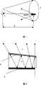
图1是普通均匀照明探测装置图。Figure 1 is a general uniform illumination detection device diagram.
图2是多束分光光学器件原理图。Fig. 2 is a schematic diagram of a multi-beam splitting optical device.
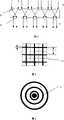
图3是微透镜实现区域化照明原理图。Fig. 3 is a schematic diagram of regionalized lighting realized by microlenses.
图4是网格结构照明结构图,其中黑色区域表示被照明区域。Fig. 4 is a grid structure lighting structure diagram, in which the black area represents the illuminated area.
图5是多环状照明结构图,其中黑色区域表示被照明区域。Fig. 5 is a multi-ring lighting structure diagram, wherein the black area represents the illuminated area.
图6是区域化照明探测探测应用示意图。Fig. 6 is a schematic diagram of an application of regionalized illumination detection detection.
图中:1.光源,2.被探测区域,3.被测物体,4.探测器,5.全反射膜,6.部分反射膜,7.条形入射光,8.非平行条形输出光,9.条形反射光,10.平面入射光,11.平行条形出射光,12.入射面, 13.出射面, 14.网格状有光区域,15.多环状有光区域。In the figure: 1. Light source, 2. Detected area, 3. Measured object, 4. Detector, 5. Total reflection film, 6. Partial reflection film, 7. Strip incident light, 8. Non-parallel strip output Light, 9. Strip reflected light, 10. Plane incident light, 11. Parallel strip exit light, 12. Incident surface, 13. Exit surface, 14. Grid-like light area, 15. Multi-ring light area .
具体实施方式Detailed ways
下面结合附图和实施例对本发明作进一步说明。The present invention will be further described below in conjunction with drawings and embodiments.
一、基本探测原理:1. Basic detection principle:
如图1所示,光自光源1发出照亮被探测区域2,被测物体3的漫反射光被探测器4所接收的光能量为:As shown in Figure 1, the light emitted from the
其中,β是损耗系数与气候、光学系统有关,IO是光源的总出射能量,SO是被测物体被光源照明的面积,SR是接收光学系统的接收面积,SD是光源的总照射面积,R是被测物体到探测器的距离。Among them, β is the loss coefficient related to climate and optical system, IO is the total outgoing energy of the light source, SO is the area of the measured object illuminated by the light source, SR is the receiving area of the receiving optical system, andSD is the total output energy of the light source. Irradiated area, R is the distance from the measured object to the detector.
为了探测细线状物体,只需要将照明整个探测区域的某些子区域,且线状物体必然能穿过这些子区域,则细线状物体就可以被探测到,且被照亮部分有更强的反射光,从而更容易被探测到。In order to detect thin line objects, it is only necessary to illuminate some sub-areas of the entire detection area, and the line objects must pass through these sub-areas, then the thin line objects can be detected, and the illuminated part has more Strong reflected light, thus easier to be detected.
若子区域的面积为SS,则此时探测器4接收到的光能量为:If the area of the sub-region is SS , then the light energy received by the
其中γ为因形成区域化照明而造成的光能损失系数,由(1)、(2)式可以知道能量增强为:Among them, γ is the light energy loss coefficient caused by the formation of regionalized lighting. From (1) and (2), it can be known that the energy enhancement is:
在均匀照明条件下对线状物体探测到的面积是区域化照明条件下的SD/SS倍,信噪比降低:Under uniform lighting conditions, the detected area of linear objects isSD /SS times that under regionalized lighting conditions, and the signal-to-noise ratio is reduced:
可见,采用区域化照明技术可以使得细小目标获得的信息量为均匀照明的:It can be seen that the use of regionalized lighting technology can make the amount of information obtained by small targets uniformly illuminated:
二、实现区域化照明的具体方法:Second, the specific method of realizing regional lighting:
既可以采用分束,微镜阵列,也可以由干涉衍射光学器件来获得区域化照明。Either beam splitting, micromirror arrays, or interference diffractive optics can be used to obtain regionalized illumination.
实施例1:Example 1:
如果采用分束的方法来区域化照明,则需要先对光源发出的光进行整形扩束调整发散角,形成条形入射光7,然后通过分束装置,最后进行组合来获得需要的照明结构。如图2所示的光学器件由两个有一定夹角的光学平面构成,该夹角与光的发散角与分束光线的条数有关,其中一个光学平面镀全反射膜5,另外一个光学平面镀能反射部分光线的部分反射膜6。这样当一线状光束照射到部分反射膜6以后,部分光出射,部分光反射再经全反射膜5反射再次到达部分反射膜6,又有部分光能出射……,这样就能将一束光分割成若干成一定夹角的光束,从而形成非平行条形输出光8。将两个这样的分束装置垂直排列,将形成网格状有光区域14,这样就可以获得如图4所示的网格状区域化照明结构。If the method of beam splitting is used for regionalized lighting, it is necessary to shape and expand the beam of the light emitted by the light source to adjust the divergence angle to form a strip of
实施例2:Example 2:
如果采用微镜阵列,则先需要对光源发出的光整形,获得平面入射光10通过微镜形成平行条纹11,通过调整入射面12与出射面13的光学结构,这样就获得需要的照明微结构,再通过整形(扩束)光学器件来获得需要的区域化照明结构。如图3所示的光学器件就可以将光束分割成需要的阵列结构,再经过光学器件(如凸透镜、凹透镜)将光束发散成一定角度,将形成网格状有光区域14或者将形成多环状有光区域15,就可以获得如图4所示的网格状区域化照明结构或者如图5的多圆环区域化照明结构。If a micromirror array is used, it is first necessary to shape the light emitted by the light source to obtain plane incident light 10 to form
实施例3:Example 3:
如果采用干涉衍射光学器件,一般也需要先对光源发出的光整形,然后通过干涉衍射光学器件获得需要的照明结构,再通过调整光束发散角来获得需要的区域化照明结构。采用法布里一珀罗干涉仪就将形成多环状有光区域15,这样就可以获得如图5所示的多环状区域化照明结构。If the interference diffraction optical device is used, it is generally necessary to shape the light emitted by the light source first, then obtain the required illumination structure through the interference diffraction optical device, and then obtain the required regionalized illumination structure by adjusting the beam divergence angle. Using a Fabry-Perot interferometer will form a
以网格状区域照明结构为例,设凝视照明一个象素对应场景区域的尺寸为L,而区域化照明的线宽为1,则
如图6所示,由1区域化部分以区域化照明方式照亮被测物体,反射光被2光学成像部分接受,并由3阵列式探测器接收。由上所述,于采用了区域化照明方式,得到的细小目标的信噪比得到了有效提高。同时,因为未被照明区域包含直线的最大长度小于最小被探测目标的最大长度,所以总能使被探测目标被主动照明光照亮,提高被探测目标的信噪比。As shown in Fig. 6, the measured object is illuminated by the 1 regionalized part in a regionalized lighting manner, and the reflected light is received by the 2 optical imaging part and received by the 3 array detector. From the above, the signal-to-noise ratio of the small target is effectively improved by adopting the regionalized lighting method. At the same time, because the maximum length of the straight line contained in the unilluminated area is smaller than the maximum length of the smallest detected object, the detected object can always be illuminated by the active illumination light, and the signal-to-noise ratio of the detected object can be improved.
Claims (6)
Translated fromChinesePriority Applications (1)
| Application Number | Priority Date | Filing Date | Title |
|---|---|---|---|
| CNB2006100505247ACN100365436C (en) | 2006-04-26 | 2006-04-26 | A Method of Regionalized Lighting Detection |
Applications Claiming Priority (1)
| Application Number | Priority Date | Filing Date | Title |
|---|---|---|---|
| CNB2006100505247ACN100365436C (en) | 2006-04-26 | 2006-04-26 | A Method of Regionalized Lighting Detection |
Publications (2)
| Publication Number | Publication Date |
|---|---|
| CN1837852A CN1837852A (en) | 2006-09-27 |
| CN100365436Ctrue CN100365436C (en) | 2008-01-30 |
Family
ID=37015304
Family Applications (1)
| Application Number | Title | Priority Date | Filing Date |
|---|---|---|---|
| CNB2006100505247AExpired - Fee RelatedCN100365436C (en) | 2006-04-26 | 2006-04-26 | A Method of Regionalized Lighting Detection |
Country Status (1)
| Country | Link |
|---|---|
| CN (1) | CN100365436C (en) |
Families Citing this family (3)
| Publication number | Priority date | Publication date | Assignee | Title |
|---|---|---|---|---|
| CN102200593A (en)* | 2011-04-29 | 2011-09-28 | 浙江师范大学 | Optical component, lighting device, method, and interferometer using device |
| TWI699496B (en)* | 2017-03-31 | 2020-07-21 | 億光電子工業股份有限公司 | Light-emitting device and lighting module |
| CN109390456A (en) | 2017-08-04 | 2019-02-26 | 亿光电子工业股份有限公司 | LED packaging structure and manufacturing method thereof |
Citations (6)
| Publication number | Priority date | Publication date | Assignee | Title |
|---|---|---|---|---|
| CN1057910A (en)* | 1990-07-04 | 1992-01-15 | 中国科学院长春光学精密机械研究所 | Scanning multispectral microscopic imaging method and device thereof |
| EP1178333A2 (en)* | 2000-08-03 | 2002-02-06 | Eastman Kodak Company | Method and apparatus for a color scannerless range imaging system |
| EP1347636A2 (en)* | 2002-03-21 | 2003-09-24 | Eastman Kodak Company | A scannerless range imaging system having high dynamic range |
| WO2005076037A1 (en)* | 2004-02-04 | 2005-08-18 | Elbit Systems Ltd. | Gated imaging |
| CN1700038A (en)* | 2005-03-25 | 2005-11-23 | 浙江大学 | Scannerless pulse-modulated three-dimensional imaging method and system |
| WO2006014470A2 (en)* | 2004-07-06 | 2006-02-09 | Dimsdale Engineering, Llc | Determining range in 3d imaging systems |
- 2006
- 2006-04-26CNCNB2006100505247Apatent/CN100365436C/ennot_activeExpired - Fee Related
Patent Citations (6)
| Publication number | Priority date | Publication date | Assignee | Title |
|---|---|---|---|---|
| CN1057910A (en)* | 1990-07-04 | 1992-01-15 | 中国科学院长春光学精密机械研究所 | Scanning multispectral microscopic imaging method and device thereof |
| EP1178333A2 (en)* | 2000-08-03 | 2002-02-06 | Eastman Kodak Company | Method and apparatus for a color scannerless range imaging system |
| EP1347636A2 (en)* | 2002-03-21 | 2003-09-24 | Eastman Kodak Company | A scannerless range imaging system having high dynamic range |
| WO2005076037A1 (en)* | 2004-02-04 | 2005-08-18 | Elbit Systems Ltd. | Gated imaging |
| WO2006014470A2 (en)* | 2004-07-06 | 2006-02-09 | Dimsdale Engineering, Llc | Determining range in 3d imaging systems |
| CN1700038A (en)* | 2005-03-25 | 2005-11-23 | 浙江大学 | Scannerless pulse-modulated three-dimensional imaging method and system |
Non-Patent Citations (5)
| Title |
|---|
| 扫描探测系统的NETD和作用距离方程. 陈汝钧.红外与毫米波学报,第15卷第3期. 1996* |
| 水下情景非同步激光照明的扫描方法. 傅金祝.水雷战与舰船防护,第2期. 2003* |
| 水下探测光电成像技术及其进展. 刘广荣,黄睿,金伟其,曹峰梅,沈飞.光学技术,第30卷第6期. 2004* |
| 焦平面探测系统的信息处理能力及其在激光测粒技术中的应用. 任中京.应用激光,第16卷第5期. 1996* |
| 红外成像导引头发现与识别概率的计算. 裴旭,马东立.红外与激光工程,第34卷第3期. 2005* |
Also Published As
| Publication number | Publication date |
|---|---|
| CN1837852A (en) | 2006-09-27 |
Similar Documents
| Publication | Publication Date | Title |
|---|---|---|
| CN107255913B (en) | Substrate processing method using same | |
| KR101946870B1 (en) | LIDAR light-emitting system improved pattern rotation | |
| CN101303270B (en) | Surface shape calibrating method of spherical surface sun heliostat | |
| EP3546984B1 (en) | Scanned linear illumination of distant objects | |
| CN102721826B (en) | Speed testing device and method of non-spliced large-target surface laser light screen | |
| CN103293678B (en) | Even laser illuminating device based on supercontinuum source | |
| CN102498387A (en) | High speed, high resolution, three dimensional solar cell inspection system | |
| EP3281035B1 (en) | Method and apparatus for computational ghost imaging | |
| CN100365436C (en) | A Method of Regionalized Lighting Detection | |
| TW202109032A (en) | Laser detection device | |
| CN110087947A (en) | Uniform light distribution is generated according to landform and the brightness measured | |
| WO2000011503A9 (en) | Laser beam expander and beam profile converter | |
| CN105223697B (en) | A kind of terahertz light expands uniforming device | |
| US9625810B2 (en) | Source multiplexing illumination for mask inspection | |
| CN105866969A (en) | Method of increasing laser far-field light spot uniformity based on light ladder | |
| US8917432B2 (en) | Multiplexing EUV sources in reticle inspection | |
| CN104459999A (en) | Illuminating system of imaging flow cytometry | |
| JP3187343U (en) | Solar simulator | |
| Knight et al. | Two-dimensional tomographs using range measurements | |
| CN112327316A (en) | Radar ranging method and laser radar | |
| CN209928053U (en) | Light emitting structure and lighting system | |
| CN108490594B (en) | Asymmetric reflection optical system based on micro-nano optical surface | |
| EP3726245A1 (en) | Array of independently-controllable laser diode bars for scanning a linear illumination pattern | |
| Okumura et al. | Prototyping of hexagonal light concentrators for the Large-Sized Telescopes of the Cherenkov Telescope Array | |
| CN104267493A (en) | Array lens type laser guide star system |
Legal Events
| Date | Code | Title | Description |
|---|---|---|---|
| C06 | Publication | ||
| PB01 | Publication | ||
| C10 | Entry into substantive examination | ||
| SE01 | Entry into force of request for substantive examination | ||
| C14 | Grant of patent or utility model | ||
| GR01 | Patent grant | ||
| C17 | Cessation of patent right | ||
| CF01 | Termination of patent right due to non-payment of annual fee | Granted publication date:20080130 Termination date:20130426 |