CN100363155C - Adjustable spanner - Google Patents
Adjustable spannerDownload PDFInfo
- Publication number
- CN100363155C CN100363155CCNB02149827XACN02149827ACN100363155CCN 100363155 CCN100363155 CCN 100363155CCN B02149827X ACNB02149827X ACN B02149827XACN 02149827 ACN02149827 ACN 02149827ACN 100363155 CCN100363155 CCN 100363155C
- Authority
- CN
- China
- Prior art keywords
- movable block
- holding tank
- clamping
- adjustment
- perforation
- Prior art date
- Legal status (The legal status is an assumption and is not a legal conclusion. Google has not performed a legal analysis and makes no representation as to the accuracy of the status listed.)
- Expired - Fee Related
Links
- 238000006073displacement reactionMethods0.000claimsabstractdescription9
- 230000002093peripheral effectEffects0.000claimsdescription2
- 238000007789sealingMethods0.000claims2
- 238000010586diagramMethods0.000description12
- 230000000694effectsEffects0.000description5
- 238000000034methodMethods0.000description5
- 230000000903blocking effectEffects0.000description4
- 238000004519manufacturing processMethods0.000description3
- 125000006850spacer groupChemical group0.000description2
Images


Landscapes
- Details Of Spanners, Wrenches, And Screw Drivers And Accessories (AREA)
Abstract
Description
Translated fromChinese[技术领域][technical field]
本发明是关于一种扳手,特别是关于一种可调式扳手。The present invention relates to a wrench, in particular to an adjustable wrench.
[背景技术][Background technique]
在传统产业中,手工具产品占有大量的外销市场,其必须在品质、实用性及良好操作性等方面均占有优势,才能抢占外销的市场,而手工具的制造方式及过程直接与成本及生产速度息息相关,这也是现今提高手工具市场竞争力的重要环节。In traditional industries, hand tool products occupy a large number of export markets. They must have advantages in quality, practicability, and good operability in order to seize the export market. The manufacturing method and process of hand tools are directly related to cost and production. Speed is closely related, which is also an important link to improve the competitiveness of hand tools market today.
而如图1所示,为美国专利第5,415,064号的扳手结构图,其显示一扳手100具有一夹持部101,夹持部101具有一夹持槽102及一调整槽103,该夹持槽102具有第一、二夹持面104、105;一调整块106容纳在调整槽103,并受一调整螺杆107穿伸,而该调整螺杆107一端伸入夹持槽102;一活动块108是位于夹持槽102内,并与调整螺杆107该端螺合,而藉旋转调整块106,使活动块108顺着调整螺杆107轴向位移;藉此,当一螺件109结合在夹持槽102内,该螺件109的第一端面109a与第二端面109b抵靠着夹持槽102的第一、二夹持面104、105,而第三端面109c则受调整块106旋转而位移的活动块108所抵靠,而使该扳手100可作顺向或是逆向的单向扳动;然而在扳动过程中,扳手100可能受扳动环境的限制,而无法作过大的角度旋摆,(亦即无法作一相对螺件109的空转动作),因此该扳手100的夹持槽102势必要离开螺件109,而将扳手100拿起,而回到可扳动的位置,并再次地将夹持槽102结合于螺件109,才能继续维持同一方向的扳动,此一方法使得扳动螺件的时间变长,造成操作上的不便,因此该扳手100有加以改良的必要。And as shown in Figure 1, it is the wrench structure diagram of U.S. Patent No. 5,415,064, which shows that a
而如图2所示,为美国专利第2,376,764号的图3所示的扳手结构图,其显示一扳手200具有一夹持部201,夹持部201具有一夹持槽202及一调整槽203,该夹持槽202内缘壁具有一齿状的夹持面204;一调整块205容纳在调整槽203,并受一调整螺杆206穿伸,而该调整螺杆206一端伸入夹持槽202;一活动块207是位于夹持槽202内,并与夹持面204对应设有一齿状夹持面208,而该活动块207与调整螺杆206螺合,而藉旋转调整块205,使活动块207顺着调整螺杆206轴向位移;藉此,当螺件结合在夹持槽202内,螺件的端面为夹持面204、208受抵靠,而使该扳手200可作顺向或是逆向的单向扳动,该扳手200的齿状夹持面204、208为一固定状,故该扳手200如同前述结构一样,在扳动过程中无法往复操作,亦无法相对螺件作空转动作,而造成操作不便,也具有加以改良的必要。And as shown in FIG. 2 , it is the wrench structure diagram shown in FIG. 3 of U.S. Patent No. 2,376,764, which shows that a
[发明内容][Content of the invention]
本发明的目的在于提供一种可调式扳手,可以相对螺件作空转退位动作,而具有往复操作功能,操作十分方便,可提高工作效率。The purpose of the present invention is to provide an adjustable wrench, which can perform idling abdication relative to the screw, and has the function of reciprocating operation. The operation is very convenient and the work efficiency can be improved.
本发明提供一种可调式扳手,包括有:The present invention provides an adjustable wrench, including:
一扳手本体,其一端具有一握把,另端具有一夹持槽,该夹持槽具有第一端及第二端;A wrench body, one end has a grip, the other end has a clamping groove, and the clamping groove has a first end and a second end;
一活动块,是滑设在该夹持槽第一端及第二端之间,并具有第一面及第二面;A movable block is slidably arranged between the first end and the second end of the clamping groove, and has a first surface and a second surface;
一调整装置,是设置在该扳手本体上,其一端与该活动块第二面结合,且藉由该调整装置的调整,而能连动该活动块于夹持槽内产生位移;An adjustment device is arranged on the wrench body, one end of which is combined with the second surface of the movable block, and through the adjustment of the adjustment device, the movable block can be linked to generate displacement in the clamping groove;
其特征在于:还包括一夹持构件,是可弹性地设置在该活动块第一面,且可相对该活动块产生弹性位移关系;该夹持构件一端斜向设置有制齿;It is characterized in that: it also includes a clamping member, which can be elastically arranged on the first surface of the movable block, and can generate an elastic displacement relationship relative to the movable block; one end of the clamping member is obliquely provided with teeth;
该活动块第二面两侧边具有第一侧壁及第二侧壁,该第二侧壁具有一穿孔由该第一面透出,该夹持构件结合一弹簧而容纳于该穿孔内,并受该弹簧所顶持。The two sides of the second surface of the movable block have a first side wall and a second side wall, and the second side wall has a perforation protruding from the first surface, and the clamping member is combined with a spring to be accommodated in the perforation, And supported by the spring.
藉此,当一螺件结合在该夹持槽内时,该螺件外缘端面受该夹持槽第一端与该该夹持构件所夹持,而使该扳手本体具有往复式地扳动功效。Thereby, when a screw is combined in the clamping groove, the outer edge end surface of the screw is clamped by the first end of the clamping groove and the clamping member, so that the wrench body has a reciprocating wrench Dynamic effect.
本发明的可调式扳手,还可以具有如下附加的技术特征:The adjustable wrench of the present invention can also have the following additional technical features:
该调整装置可包括有一调整块及一调整螺杆,而该夹持槽连通一调整槽,该调整块容纳在该调整槽内,而该调整螺杆穿过扳手本体及该调整块,并凸露于该夹持槽,与该活动块第二面结合。The adjustment device may include an adjustment block and an adjustment screw, and the clamping groove communicates with an adjustment groove, the adjustment block is accommodated in the adjustment groove, and the adjustment screw passes through the wrench body and the adjustment block, and protrudes on the The clamping groove is combined with the second surface of the movable block.
该夹持槽的第一端可具有第一夹持面及第二夹持面,而能配合该夹持构件夹持螺件。The first end of the clamping groove can have a first clamping surface and a second clamping surface, and can cooperate with the clamping member to clamp the screw.
该夹持构件凸出于该活动块第一面。The clamping member protrudes from the first surface of the movable block.
该夹持构件具有一凸部,而该穿孔内具有一挡部,该夹持构件装设在该穿孔内,该凸部抵靠在该挡部,该夹持构件尾端受一塞体封闭而限位于该穿孔内。The clamping member has a convex portion, and the through hole has a blocking portion, the clamping member is installed in the through hole, the convex portion abuts against the blocking portion, and the tail end of the clamping member is closed by a plug And limited in the perforation.
本发明还提供一种可调式扳手,包括有:The present invention also provides an adjustable wrench, including:
一扳手本体,其一端具有一握把,另端具有一夹持槽,该夹持槽具有第一端及第二端;A wrench body, one end has a grip, the other end has a clamping groove, and the clamping groove has a first end and a second end;
一活动块,是滑设在夹持槽第一端及第二端之间;A movable block is slidably arranged between the first end and the second end of the clamping groove;
一调整装置,是设置在扳手本体上,其一端与活动块结合,且藉由该调整装置的调整,而能连动该活动块于该夹持槽内产生位移;An adjustment device is arranged on the wrench body, one end of which is combined with the movable block, and through the adjustment of the adjustment device, the movable block can be linked to generate displacement in the clamping groove;
其特征在于:还包括一夹持构件,是可弹性地设置在该夹持槽第一端,且可相对该夹持槽产生弹性位移关系;该夹持构件一端斜向设置有制齿;It is characterized in that: it also includes a clamping member, which can be elastically arranged at the first end of the clamping groove, and can generate an elastic displacement relationship relative to the clamping groove; one end of the clamping member is obliquely provided with teeth;
该夹持槽外周缘具有第一侧壁及第二侧壁,第一侧壁具有一穿孔与该夹持槽连通,该夹持构件结合一弹簧而容纳于该穿孔内,并受该弹簧所顶持。The outer peripheral edge of the clamping groove has a first side wall and a second side wall, the first side wall has a through hole communicating with the clamping groove, the clamping member is accommodated in the through hole combined with a spring, and is held by the spring Uphold.
上述的可调式扳手,还可以具有如下附加的技术特征:The above-mentioned adjustable wrench can also have the following additional technical features:
该调整装置可包括有一调整块及一调整螺杆,而该夹持槽连通一调整槽,该调整块容纳在该调整槽内,而该调整螺杆穿过扳手本体及调整块,并凸露于该夹持槽,与该活动块结合。The adjustment device may include an adjustment block and an adjustment screw, and the clamping groove communicates with an adjustment groove, the adjustment block is accommodated in the adjustment groove, and the adjustment screw passes through the wrench body and the adjustment block, and protrudes from the The clamping groove is combined with the movable block.
该活动块具有第一夹持面及第二夹持面。The movable block has a first clamping surface and a second clamping surface.
该夹持构件凸伸于该夹持槽第一端。The clamping member protrudes from the first end of the clamping groove.
该夹持构件具有一凸部,而该穿孔内具有一挡部,该夹持构件装设在该穿孔内,该凸部抵靠在该挡部,该夹持构件尾端受一塞体封闭而限位于该穿孔内。The clamping member has a convex portion, and the through hole has a blocking portion, the clamping member is installed in the through hole, the convex portion abuts against the blocking portion, and the tail end of the clamping member is closed by a plug And limited in the perforation.
综上所述可以归纳出本发明具有以下的优点:In summary, it can be concluded that the present invention has the following advantages:
1、本发明的可调式扳手,其中藉夹持槽第一端设置有夹持构件,以及在活动块第一面上设置夹持构件,且藉由夹持构件受弹簧的顶持,而能使螺件结合于夹持槽内,受夹持构件的夹持,而使该可调式扳手具有顺时针方向或逆时针方向的往复扳动的操作功效。1. The adjustable wrench of the present invention, wherein the first end of the clamping groove is provided with a clamping member, and the clamping member is arranged on the first surface of the movable block, and the clamping member is supported by the spring, so that The screw is combined in the clamping groove and clamped by the clamping member, so that the adjustable wrench has the operation effect of clockwise or counterclockwise reciprocating pulling.
2、本发明的可调式扳手,其中藉螺件结合在夹持槽内时,该螺件外缘端面受弹簧顶持的夹持构件所夹持,而使该扳手具有往复式地扳动功效,而使得工作者无需拿起扳手,与螺件再次套接,只需运用具弹性夹持构件的设置,即能往复地操作,因此,该可调式扳手确实具有产业上的利用性。2. The adjustable wrench of the present invention, wherein when the screw is combined in the clamping groove, the outer edge end surface of the screw is clamped by the clamping member supported by the spring, so that the wrench has a reciprocating pulling effect , so that the worker does not need to pick up the wrench to re-socket with the screw, and only needs to use the setting of the elastic clamping member to operate reciprocally. Therefore, the adjustable wrench does have industrial applicability.
[附图说明][Description of drawings]
图1:为美国专利第5,415,064号的扳手结构图;Figure 1: Structural diagram of a wrench in US Patent No. 5,415,064;
图2:为美国专利第2,376,764号的扳手结构图;Figure 2: Structural diagram of a wrench in US Patent No. 2,376,764;
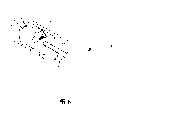
图3:为本发明第一实施例的立体外观图;Fig. 3: is the perspective view of the first embodiment of the present invention;
图4:为本发明图3所示的结构立体分解图;Fig. 4: is the three-dimensional exploded view of the structure shown in Fig. 3 of the present invention;
图5:本发明显示夹持构件是设置在活动块上,并夹持螺件的逆时针方向扳动的状态图;Figure 5: The present invention shows that the clamping member is arranged on the movable block, and the state diagram of clamping the screw is pulled in the counterclockwise direction;
图6:为延续本发明图5结构,并显示扳手本体位于顺时针方向扳动的空转状态图;Figure 6: In order to continue the structure of Figure 5 of the present invention, and show the idling state diagram of the wrench body being pulled in the clockwise direction;
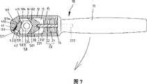
图7:显示本发明夹持构件被设置在夹持槽第一端,并夹持螺件的顺时针方向扳动状态图;Fig. 7: It shows that the clamping member of the present invention is set at the first end of the clamping groove and is pulled clockwise to clamp the screw;
图8:为延续本发明图7结构,并显示扳手本体位于逆时针方向扳动的空转状态图。Fig. 8 is a continuation of the structure of Fig. 7 of the present invention, and shows the idling state diagram of the wrench body being pulled in the counterclockwise direction.
[具体实施方式][Detailed ways]
本发明是提供一种具有往复操作功能的可调式扳手,兹配合附图将本发明的实施例详细说明如下:The present invention provides an adjustable wrench with a reciprocating operation function. The embodiments of the present invention will be described in detail as follows in conjunction with the accompanying drawings:
请先参阅图3、4所示,为本发明立体外观图及系统分解图,其包括有:Please refer to Figures 3 and 4, which are three-dimensional appearance diagrams and system exploded diagrams of the present invention, which include:
一扳手本体10,其一端为握把11,另一端为夹持部12,夹持部12纵向凹设有一夹持槽13及一调整槽14,该夹持槽13具有第一端131及第二端132,第一端131形成有呈V形的第一夹持面131a及第二夹持面131b,而夹持槽13第二端132与调整槽14之间横设有一间隔部15,该间隔部15设有一螺孔151连通该夹持槽13与该调整槽14,而该调整槽14对应螺孔151同轴设有一穿孔141;A
一调整装置20,是包括有一调整块21及一调整螺杆22,该调整块21是呈一圆柱状,并具有一螺纹孔211而容纳在调整槽14内,使螺纹孔211与前述的螺孔151及穿孔141对应,该调整螺杆22具有第一端221及第二端222,调整螺杆22第一端221伸经扳手本体10的穿孔141、调整块21的螺纹孔211及间隔部15的螺孔151,而凸伸于夹持槽13第二端132;An
一活动块30,其外周缘具有第一面31及第二面32,以及位于第二面32两侧的第一侧壁33及第二侧壁34,该第二面32具有一螺孔321,使活动块30容纳在夹持槽13内,使调整螺杆22第一端221螺入螺孔321,并可旋动调整块21,使活动块30顺着调整螺杆22轴向位移,而该活动块30第二侧壁34斜向设有一阶级状的穿孔341由第一面31透出;A
一夹持构件40,其一端斜向设有预定形状的制齿401,而制齿401侧边设有一凸部402,及一轴向设置的弹簧槽403,使该夹持构件40纳入活动块30的穿孔341,并在弹簧槽403内设置一弹簧41,且以一圆柱形的塞体42以紧配合的方式或是其他等效的锁固方式封闭穿孔341,而将夹持构件40及弹簧41限位于穿孔341内,该夹持构件40受弹簧41顶持,而使其制齿401凸出活动块30第一面31;A clamping
请参阅图5所示,本发明的扳手本体10于夹持槽13内结合一螺件50,且与该螺件50形成卡掣的逆时针方向扳动状态图,藉由旋动调整块21,使活动块30位移,并带动夹持构件40往夹持槽13第一端131移动,而能以夹持构件40的制齿401抵靠在螺件50的第一、二端面501、502,并使螺件50受顶推下,而使其第三、四端面503、504抵靠在夹持槽13的第一、二夹持面131a、131b,而为夹持构件40所夹持,其中夹符构件40受弹簧41的顶持,使其凸部402抵靠在穿孔341内的挡部341a位置上,而使夹持构件40的制齿401抵顶住螺件50第一、二端面501、502,而使扳手本体10以螺件50为旋转中心,能将螺件50逆时针方向扳动;Please refer to FIG. 5 , the
而如图6所示,显示扳手本体10位于顺时针方向扳动的空转状态图,其藉夹持构件40的制齿401为斜向的设置,且为夹持构件40为弹簧41所顶持,故在扳手本体10以螺件50为旋转中心顺时针方向扳转时,夹持构件40的制齿401与螺件50第一端面501形成抵顶,且夹持构件40无支撑点支撑,故在穿孔341内缩退位,并压抵弹簧41,而能使扳手本体10形成空转状态,而藉扳动动作停止时,弹簧41再度将夹持构件40弹顶复位,使其制齿401再次顶持螺件50的第一、二端面501、502,藉由图4、5所述动作,使扳手本体10正反转操作,而能具有往复操作的扳动效果,有利于快速扳动螺件50的操作。And as shown in FIG. 6 , it shows that the
请参阅图7所示,其显示夹持构件43被设置在夹持槽13第一端131,并于夹持槽13内结合螺件50,且与该螺件50形成卡掣的顺时针方向扳动状态图,然而本实施例是根据上述的创作原理,而将夹持构件43设置在夹持槽13第一端131位置,其中,活动块30具有V形的第一、二夹持面35、36,而夹持部12外周缘设置渐缩状的第一侧壁121、第二侧壁122,而第一侧壁121设置一斜向的阶级穿孔123与夹持槽13相通,而穿孔123具有一挡部123a,使与上述实施例相同的夹持构件43置入穿孔123内,而受弹簧41顶持,使凸部432抵靠在挡部123a上;且藉由旋动调整块21使活动块30位移,并使活动块30第一、二夹持面35、36抵靠在螺件50的第一、二端面501、502,并使螺件50受顶推下,而使其第三、四端面503、504抵靠在夹持构件43的制齿431,而为夹持构件43所夹持,同样的扳手本体10以螺件50为旋转中心,而能将螺件50顺时针方向扳动;Please refer to FIG. 7 , which shows that the clamping
而如图8所示,为显示夹持构件43被设置在夹持槽13第一端131上,且扳手本体10位于逆时针方向扳动的空转状态图,其藉扳手本体10以螺件50为旋转中心逆时针方向扳转时,且夹持构件43于穿孔123内缩退位,并压抵弹簧41,而能使扳手本体10形成空转状态,使其夹持构件43装设在夹持槽13内缘端壁上亦能具有往复操作的扳动效果。And as shown in FIG. 8 , in order to show that the clamping
Claims (10)
Priority Applications (1)
| Application Number | Priority Date | Filing Date | Title |
|---|---|---|---|
| CNB02149827XACN100363155C (en) | 2002-11-06 | 2002-11-06 | Adjustable spanner |
Applications Claiming Priority (1)
| Application Number | Priority Date | Filing Date | Title |
|---|---|---|---|
| CNB02149827XACN100363155C (en) | 2002-11-06 | 2002-11-06 | Adjustable spanner |
Publications (2)
| Publication Number | Publication Date |
|---|---|
| CN1498727A CN1498727A (en) | 2004-05-26 |
| CN100363155Ctrue CN100363155C (en) | 2008-01-23 |
Family
ID=34233801
Family Applications (1)
| Application Number | Title | Priority Date | Filing Date |
|---|---|---|---|
| CNB02149827XAExpired - Fee RelatedCN100363155C (en) | 2002-11-06 | 2002-11-06 | Adjustable spanner |
Country Status (1)
| Country | Link |
|---|---|
| CN (1) | CN100363155C (en) |
Cited By (1)
| Publication number | Priority date | Publication date | Assignee | Title |
|---|---|---|---|---|
| TWI779540B (en)* | 2021-03-30 | 2022-10-01 | 穩陞工業股份有限公司 | Wrench structure |
Families Citing this family (2)
| Publication number | Priority date | Publication date | Assignee | Title |
|---|---|---|---|---|
| CN108177113A (en)* | 2017-12-27 | 2018-06-19 | 大连民族大学 | A kind of monkey wrench |
| CN111331541A (en)* | 2020-03-06 | 2020-06-26 | 于帅博 | Electrodeless sleeve |
Citations (5)
| Publication number | Priority date | Publication date | Assignee | Title |
|---|---|---|---|---|
| CN2136107Y (en)* | 1992-08-22 | 1993-06-16 | 许忠庆 | socket wrench |
| US5415064A (en)* | 1994-03-16 | 1995-05-16 | Chang; Chung-Hshing | Adjustable wrench |
| US5454283A (en)* | 1991-09-25 | 1995-10-03 | Stefano; Jerry Di. | Ratchet line wrench tool |
| JP2001105334A (en)* | 1999-09-30 | 2001-04-17 | Top Kogyo Kk | Wrench |
| CN2485097Y (en)* | 2001-06-22 | 2002-04-10 | 郭文进 | Adjustment structure of ratchet wrench |
- 2002
- 2002-11-06CNCNB02149827XApatent/CN100363155C/ennot_activeExpired - Fee Related
Patent Citations (5)
| Publication number | Priority date | Publication date | Assignee | Title |
|---|---|---|---|---|
| US5454283A (en)* | 1991-09-25 | 1995-10-03 | Stefano; Jerry Di. | Ratchet line wrench tool |
| CN2136107Y (en)* | 1992-08-22 | 1993-06-16 | 许忠庆 | socket wrench |
| US5415064A (en)* | 1994-03-16 | 1995-05-16 | Chang; Chung-Hshing | Adjustable wrench |
| JP2001105334A (en)* | 1999-09-30 | 2001-04-17 | Top Kogyo Kk | Wrench |
| CN2485097Y (en)* | 2001-06-22 | 2002-04-10 | 郭文进 | Adjustment structure of ratchet wrench |
Cited By (1)
| Publication number | Priority date | Publication date | Assignee | Title |
|---|---|---|---|---|
| TWI779540B (en)* | 2021-03-30 | 2022-10-01 | 穩陞工業股份有限公司 | Wrench structure |
Also Published As
| Publication number | Publication date |
|---|---|
| CN1498727A (en) | 2004-05-26 |
Similar Documents
| Publication | Publication Date | Title |
|---|---|---|
| US7270035B2 (en) | Single-wedge wrenches | |
| WO2004102013A3 (en) | Insert retention screw and tool body and insert therewith | |
| US1369829A (en) | Compound tool | |
| CN100363155C (en) | Adjustable spanner | |
| US20090193941A1 (en) | Ratchet Wrench | |
| US4974478A (en) | Device for tightening the screw on scissors | |
| US3730237A (en) | Screw-supporting attachment for the shank of a screw driver tool | |
| CN212240118U (en) | Holds a stable vise | |
| US20080216615A1 (en) | Structure of pliers | |
| CN2808434Y (en) | Improved structure of clamp | |
| US2566683A (en) | Screw-holding screw driver | |
| US7520690B2 (en) | Part positioner and part pressing member | |
| CN2424881Y (en) | Ratchet wrench with high torque and small angle change | |
| TW201618904A (en) | Pipe wrench structure | |
| TWI576207B (en) | Floating air pressure angle solid double clamp vise structure | |
| CN2759665Y (en) | The adjustment structure of the tapping device | |
| JP3062739U (en) | Fast forward / fast vise | |
| CN2569979Y (en) | Structural improvement of one-way ratchet wrench | |
| CN106141969B (en) | A kind of adjustable hook-headed wrench | |
| JP2005169607A (en) | Ratchet type monkey wrench | |
| CN222371487U (en) | Torque wrench | |
| CN2467269Y (en) | a wrench structure | |
| US20220072686A1 (en) | Powered Compression Clamping System | |
| CN2413857Y (en) | Modified monkey wrench | |
| CN2553971Y (en) | Thread cutter with improved structure |
Legal Events
| Date | Code | Title | Description |
|---|---|---|---|
| C06 | Publication | ||
| PB01 | Publication | ||
| C10 | Entry into substantive examination | ||
| SE01 | Entry into force of request for substantive examination | ||
| C14 | Grant of patent or utility model | ||
| GR01 | Patent grant | ||
| C17 | Cessation of patent right | ||
| CF01 | Termination of patent right due to non-payment of annual fee | Granted publication date:20080123 Termination date:20091207 |