CN100341292C - Distributed substation network combining method - Google Patents
Distributed substation network combining methodDownload PDFInfo
- Publication number
- CN100341292C CN100341292CCNB2004100004776ACN200410000477ACN100341292CCN 100341292 CCN100341292 CCN 100341292CCN B2004100004776 ACNB2004100004776 ACN B2004100004776ACN 200410000477 ACN200410000477 ACN 200410000477ACN 100341292 CCN100341292 CCN 100341292C
- Authority
- CN
- China
- Prior art keywords
- radio frequency
- frequency part
- baseband
- optical fiber
- level
- Prior art date
- Legal status (The legal status is an assumption and is not a legal conclusion. Google has not performed a legal analysis and makes no representation as to the accuracy of the status listed.)
- Expired - Lifetime
Links
Images


Landscapes
- Optical Communication System (AREA)
Abstract
Translated fromChinese
Description
Translated fromChinese技术领域technical field
本发明涉及无线通信系统中的基站,特别涉及一种分布式基站的组网方法。The invention relates to a base station in a wireless communication system, in particular to a method for forming a network of a distributed base station.
背景技术Background technique
在无线通信系统的分布式基站中,一个基带部分(REC)可以控制多个射频部分(RE)。目前,基带部分和射频部分的接口标准(CPRI)规范中尚未考虑级连的情况,因此,链形、树形、环形都无法支持,如果一个REC要带多个RE的话,只能采用星形连接。In a distributed base station of a wireless communication system, one baseband part (REC) can control multiple radio frequency parts (RE). At present, the interface standard (CPRI) of the baseband part and the radio frequency part has not considered the cascade connection. Therefore, the chain, tree, and ring cannot be supported. If a REC needs to carry multiple REs, it can only use a star connect.
参见图1,图1为现有技术中分布式基站星形组网示意图。图1中一个REC与RE1、RE2、RE3三个RE分别相连,在这种星形连接的情况下,REC为每个RE单独拉一对光纤,同时REC为每个RE提供一个光口。在某些场合下,星形组网对传输资源的浪费比较严重。例如,当在高速公路上时,REC、RE可能呈一字形排列,假设REC与第一个RE之间相距5Km,每两个RE之间相距也是5Km,如果采用链形组网,可以从REC连一对5Km的光纤到第一级RE1,再从第一级RE1连一对5Km的光线到第二级RE2。但在星形组网时,只能从REC分别拉5Km和10Km的光纤到RE1和RE2,比链形组网多用了5Km的光纤,并多占用了REC的一个光口。这在一个大容量REC带很多小容量RE时是很不经济的。Referring to FIG. 1 , FIG. 1 is a schematic diagram of a star network of distributed base stations in the prior art. In Figure 1, one REC is connected to RE1, RE2, and RE3 respectively. In this star connection, the REC pulls a pair of optical fibers for each RE, and the REC provides an optical port for each RE. In some cases, the waste of transmission resources in a star network is serious. For example, when you are on a highway, REC and RE may be arranged in a straight line. Suppose the distance between REC and the first RE is 5Km, and the distance between every two REs is also 5Km. Connect a pair of 5Km optical fibers to the first stage RE1, and then connect a pair of 5Km optical fibers from the first stage RE1 to the second stage RE2. But in the star network, only 5Km and 10Km of optical fiber can be pulled from REC to RE1 and RE2 respectively, which uses 5Km more optical fiber than the chain network and occupies one more optical port of REC. This is very uneconomical when a large-capacity REC carries many small-capacity REs.
所以,如何采用级连的方式实现链形、环形组网,减少传输资源浪费是目前分布式基站技术中急需解决的问题。Therefore, how to adopt cascade connection to implement chain and ring networking and reduce the waste of transmission resources is an urgent problem to be solved in the current distributed base station technology.
发明内容Contents of the invention
有鉴于此,本发明的主要目的在于提供一种分布式基站的组网方法,能够将分布式基站中射频部分级连起来,减少传输资源的浪费,降低组网成本。In view of this, the main purpose of the present invention is to provide a distributed base station networking method, which can connect the radio frequency parts of the distributed base stations in stages, reduce the waste of transmission resources, and reduce the networking cost.
为达到上述目的,本发明的技术方案具体是这样实现的:In order to achieve the above object, the technical solution of the present invention is specifically realized in the following way:
一种分布式基站的组网方法,该方法包括以下步骤:A method for networking a distributed base station, the method comprising the following steps:
1)为分布式基站中的基带部分和每个射频部分分别设置两个或两个以上光口;1) Two or more optical ports are respectively set for the baseband part and each radio frequency part in the distributed base station;
2)将分布式基站中的基带部分和射频部分通过步骤1)所述的光口使用光纤级连成环形网;2) the baseband part and the radio frequency part in the distributed base station are connected into a ring network using the optical fiber level through the optical port described in step 1);
3)射频部分启动后,监听与其相连的光纤上传输的接口信息;3) After the radio frequency part is started, monitor the interface information transmitted on the optical fiber connected to it;
4)基带部分启动后,设置环形网中的一段光纤为备用光纤,并在接口信息中增加光纤的主备属性和该光纤连接的射频部分的上下级属性;4) After the baseband part is started, set a section of optical fiber in the ring network as the standby optical fiber, and increase the master-standby attribute of the optical fiber and the upper-lower-level attribute of the radio frequency part connected by the optical fiber in the interface information;
5)基带部分通过级连的各个射频部分逐级向各个射频部分发送接口信息,通知各个射频部分其所连光纤的主备属性;射频部分在向下一级射频部分发送的接口信息中指明自己为上级射频部分;5) The baseband part sends interface information to each radio frequency part step by step through each radio frequency part of the cascade, and notifies each radio part of the active and standby attributes of the optical fiber it is connected to; the radio frequency part specifies itself in the interface information sent to the lower radio frequency part It is the upper radio frequency part;
6)射频部分监听到与其相连光纤上传输的接口信息后,从基带部分或上级射频部分发送的接口信息中获得该光纤链路的主备属性和本射频部分的上下级属性。6) After the radio frequency part monitors the interface information transmitted on the optical fiber connected to it, it obtains the master and backup attributes of the optical fiber link and the upper and lower level attributes of the radio frequency part from the interface information sent by the baseband part or the upper radio frequency part.
其中,步骤3)所述监听与其相连的光纤上传输接口信息的方法可以为:射频部分向与其相邻的基带部分或射频部分发送接口信息,通知所述基带部分或射频部分光纤属性未知,等待该基带部分或射频部分返回光纤的主备属性和该基带部分或射频部分的上下级属性。Wherein, step 3) the method for monitoring the transmission interface information on the optical fiber connected to it can be: the radio frequency part sends the interface information to the baseband part or the radio frequency part adjacent to it, informs the baseband part or the radio frequency part that the optical fiber attribute is unknown, and waits The baseband part or the radio frequency part returns the active/standby attribute of the optical fiber and the upper and lower level attributes of the baseband part or the radio frequency part.
当射频部分已知其为相邻基带部分或射频部分的下级时,可以向该基带部分或射频部分发送接口信息,通知该基带部分或射频部分光纤属性未知,等待该基带部分或射频部分返回光纤的主备属性。When the radio frequency part knows that it is the subordinate of the adjacent baseband part or radio frequency part, it can send interface information to the baseband part or radio frequency part, inform the baseband part or radio frequency part that the fiber attribute is unknown, and wait for the baseband part or radio frequency part to return to the fiber primary and secondary attributes.
该方法可以进一步包括:当射频部分与基带部分失去联系时,射频部分重新监听与其相连光纤上传输的接口信息。The method may further include: when the radio frequency part loses contact with the baseband part, the radio frequency part re-monitors the interface information transmitted on the optical fiber connected to it.
当该方法应用到基带部分和射频部分的接口标准CPRI接口时,所述光纤的主备属性可以与接口信息中原有的业务接入点故障指示SDI比特复用。When the method is applied to the interface standard CPRI interface of the baseband part and the radio frequency part, the active/standby attribute of the optical fiber can be multiplexed with the original service access point fault indication SDI bit in the interface information.
所述步骤5)至步骤6)包括环形网启动过程,该过程包括以下步骤:Described step 5) to step 6) comprises the ring network starting process, and this process comprises the following steps:
A、启动基带部分,基带部分根据配置信息得知整个环的结构,然后决定哪一段光纤是备用光纤;A. Start the baseband part. The baseband part knows the structure of the entire ring according to the configuration information, and then decides which section of optical fiber is the spare optical fiber;
B、基带部分与第一级的所有射频部分分别互相取得同步;B. The baseband part and all radio frequency parts of the first stage are synchronized with each other;
C、基带部分使用HDLC链路或者以太网向第一级的所有射频部分分别发送包括了接口信息的操作维护信息,通知第一级的所有射频部分光纤的主备属性;C. The baseband part uses the HDLC link or Ethernet to send the operation and maintenance information including the interface information to all the radio frequency parts of the first level, and notifies all the radio frequency parts of the first level of the main and standby attributes of the optical fiber;
D、本级的射频部分与下一级的所有射频部分分别互相取得同步;并指明本射频部分为上级;D. The radio frequency part of this level and all the radio frequency parts of the next level are synchronized with each other; and the radio frequency part is designated as the upper level;
E、基带部分逐级与下一级的所有射频部分建立联系;E. The baseband part establishes contact with all radio frequency parts of the next level step by step;
F、基带部分使用HDLC链路或者以太网逐级向下一级的所有射频部分分别发送包括了接口信息的操作维护信息,通知下一级的所有射频部分光纤的主备属性;F. The baseband part uses the HDLC link or Ethernet to send the operation and maintenance information including the interface information to all the radio frequency parts of the next level step by step, and notifies all the radio frequency parts of the next level of the main and standby attributes of the optical fiber;
G、如果还有下一级射频部分,则重复执行步骤D-G;否则启动过程完成。G. If there is a next-level radio frequency part, repeat steps D-G; otherwise, the start-up process is completed.
步骤A中基带部分可以根据各个射频部分之间的硬件连接关系、各个射频部分的系统配置信息来得知整个环的结构,并决定哪一段为备用光纤。In step A, the baseband part can know the structure of the entire ring according to the hardware connection relationship between each radio frequency part and the system configuration information of each radio frequency part, and decide which section is the backup optical fiber.
步骤B中基带部分和射频部分间的同步过程可以为双方从启动后到互相之间能够正常通信的过程,至少包括速率适配、时钟同步、接口格式校验过程。The synchronization process between the baseband part and the radio frequency part in step B can be the process from the start to the normal communication between the two parties, including at least the process of rate adaptation, clock synchronization and interface format verification.
步骤E所述的建立联系的过程可以为:基带部分向第一级射频部分发送建立基带部分到目标射频部分之间联系的操作维护信息,第一级射频部分收到该信息后,根据其中的HDLC地址或者IP地址来判断出该信息是不是发送给自己的,如果不是,则将该信息透传给下一级,下一级以同样的方式透传给再下一级,直到目标射频部分,目标射频部分收到该信息后即建立联系。The process of establishing a connection described in step E may be: the baseband part sends to the first-level radio frequency part the operation and maintenance information for establishing the connection between the baseband part and the target radio frequency part, and after the first-level radio frequency part receives the information, according to the HDLC address or IP address to determine whether the information is sent to itself, if not, the information is transparently transmitted to the next level, and the next level is transparently transmitted to the next level in the same way until the target radio frequency part , the target RF part will establish contact after receiving this information.
步骤F所述的逐级通知光纤的主备属性的过程可以为:基带部分向第一级射频部分发送通知目标射频部分光纤的主备属性操作维护信息,第一级射频部分收到该信息后,根据其中的HDLC地址或者IP地址来判断该信息是不是发送给自己的,如果不是,则将该信息透传给下一级,下一级以同样的方式透传给再下一级,直到目标射频部分。The process of step-by-step notification of the active and standby attributes of the optical fiber described in step F may be: the baseband part sends the operation and maintenance information of the active and standby attribute of the optical fiber to the first-level radio frequency part to notify the target radio frequency part, and the first-level radio frequency part receives the information. According to the HDLC address or IP address in it, it is judged whether the information is sent to itself. If not, the information is transparently transmitted to the next level, and the next level is transparently transmitted to the next level in the same way, until Target RF section.
该方法可以进一步包括业务数据转发过程,该过程包括:The method may further include a service data forwarding process, which includes:
A、基带部分在进行业务数据转发前,先确定好各个射频部分业务数据在接口帧中的位置,并将业务数据在接口帧中的位置通过高层信令由基带部分配给各个射频部分;各个射频部分记录该位置;A. Before the baseband part forwards the service data, first determine the position of the service data of each radio part in the interface frame, and assign the position of the service data in the interface frame to each radio part by the baseband part through high-level signaling; Partially record the location;
B、射频部分收到上级发送来的业务数据时,根据记录的本射频部分业务数据在接口帧中的位置,读取该位置的业务数据;如果需要向上级返回业务数据,则将要返回的业务数据填入到上述接口帧中的位置,返回给上级;对于接口帧中非本射频部分的业务数据,则透传给下一级或透明返回给上一级。B. When the radio frequency part receives the business data sent by the superior, it reads the business data at the position according to the recorded position of the business data of the radio frequency part in the interface frame; if it needs to return the business data to the superior, the business data to be returned The data is filled into the position in the above interface frame and returned to the upper level; for the service data in the interface frame that is not part of the radio frequency, it is transparently transmitted to the next level or transparently returned to the upper level.
该方法还可以进一步包括时延测量方法,其为:基带部分测量并记录自身到下一级射频部分的传输时延和自身的处理时延,射频部分测量本设备到下一级设备的传输时延,并和自身的处理时延一起上报给基带部分;基带部分根据网络结构,将各个射频部分上报的上行时延进行累加,再加上该基带部分到下一级射频部分的上行传输时延和该基带部分的处理时延得到总的上行时延;将各个射频部分上报的下行时延,再加上该基带部分到下一级射频部分的下行传输时延和该基带部分的处理时延进行累加得到总的下行时延。The method may further include a delay measurement method, which is: the baseband part measures and records the transmission delay from itself to the next-level radio frequency part and its own processing delay, and the radio frequency part measures the transmission time from the equipment to the next-level equipment delay, and report it to the baseband part together with its own processing delay; the baseband part accumulates the uplink delay reported by each radio part according to the network structure, plus the uplink transmission delay from the baseband part to the next-level radio part and the processing delay of the baseband part to obtain the total uplink delay; the downlink delay reported by each radio frequency part, plus the downlink transmission delay from the baseband part to the next-level radio frequency part and the processing delay of the baseband part Accumulate to obtain the total downlink time delay.
该方法还可以进一步包括链路故障处理过程,该过程包括以下步骤:The method may further include a link fault handling process, which includes the following steps:
A、射频部分把到下一级射频部分的链路出现故障的信息报告给基带部分,基带部分分析故障后,确定需要激活备用光纤;A. The radio frequency part reports the failure information of the link to the next level radio frequency part to the baseband part. After the baseband part analyzes the fault, it determines that the backup optical fiber needs to be activated;
B、基带部分通知报告故障的射频部分把出现链路故障的光纤转入备用态;B. The baseband part notifies the radio frequency part that reports the failure to turn the fiber with link failure into a standby state;
C、基带部分通知与原备用光纤相连的射频部分,将该段光纤转入主用态;C. The baseband part notifies the radio frequency part connected to the original standby fiber, and transfers this section of fiber to the active state;
D、步骤C所述的射频部分与链路故障的另一端的射频部分取得同步,然后基带部分与该射频部分建立联系;基带部分通知该射频部分将出现链路故障的光纤转入备用态;D. The radio frequency part described in step C is synchronized with the radio frequency part at the other end of the link failure, and then the baseband part establishes contact with the radio frequency part; the baseband part notifies the radio frequency part to transfer the optical fiber with link failure into a standby state;
E、基带部分在新转入主用态的光纤上重新分配带宽。E. The baseband part redistributes the bandwidth on the optical fiber newly transferred to the active state.
该方法还可以进一步包括射频部分故障处理过程,该过程包括以下步骤:The method may further include a radio frequency part fault handling process, which includes the following steps:
A、基带部分对故障进行分析,确定哪个射频部分出现故障;A. The baseband part analyzes the fault to determine which radio frequency part is faulty;
B、基带部分将原备用光纤转入主用态;B. The baseband part transfers the original standby optical fiber to the active state;
C、转入主用态光纤两端的射频部分取得同步,然后基带部分和与故障射频部分相连的射频部分取得联系;基带部分通知该射频部分将其另一端与故障射频部分相连的光纤转入备用态;C. The radio frequency parts at both ends of the optical fiber in the active state are synchronized, and then the baseband part contacts the radio frequency part connected to the faulty radio frequency part; the baseband part notifies the radio frequency part to transfer the fiber connected to the faulty radio frequency part at the other end to the backup state;
D、基带部分在新转入主用态的光纤上重新分配带宽。D. The baseband part redistributes the bandwidth on the optical fiber newly transferred to the active state.
由上述的技术方案可见,本发明的这种分布式基站的组网方法,为分布式基站中的基带部分和每个射频部分分别设置两个或两个以上光口,并将分布式基站中的基带部分和射频部分通过所述的光口使用光纤级连成环形网,能够将分布式基站中射频部分级连起来,减少传输资源的浪费,降低组网成本。It can be seen from the above-mentioned technical solution that the networking method of the distributed base station of the present invention sets two or more optical ports for the baseband part and each radio frequency part in the distributed base station respectively, and connects the distributed base station The baseband part and the radio frequency part of the distributed base station are connected to form a ring network through the optical fiber level, which can connect the radio frequency part in the distributed base station to reduce the waste of transmission resources and reduce the cost of networking.
附图说明Description of drawings
图1为现有技术中分布式基站星形组网示意图;FIG. 1 is a schematic diagram of a distributed base station star network in the prior art;
图2为本发明第一较佳实施例的分布式基站环形组网示意图;FIG. 2 is a schematic diagram of a distributed base station ring network in the first preferred embodiment of the present invention;
图3为图2所示实施例中进行上、下行时延测量的原理示意图;FIG. 3 is a schematic diagram of the principle of performing uplink and downlink time delay measurement in the embodiment shown in FIG. 2;
图4为图2所示实施例链路故障处理后的链路拓扑图;Fig. 4 is the link topology diagram after the link fault processing of the embodiment shown in Fig. 2;
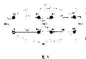
图5为图2所示实施例RE故障处理后的链路拓扑图;Fig. 5 is the link topology diagram after the RE fault processing of the embodiment shown in Fig. 2;
图6为本发明第二较佳实施例的分布式基站环形组网示意图。Fig. 6 is a schematic diagram of a ring network of distributed base stations according to a second preferred embodiment of the present invention.
具体实施方式Detailed ways
为使本发明的目的、技术方案及优点更加清楚明白,以下参照附图并举实施例,对本发明进一步详细说明。In order to make the object, technical solution and advantages of the present invention clearer, the present invention will be further described in detail below with reference to the accompanying drawings and examples.
本发明的这种分布式基站的组网方法,为分布式基站中的基带部分和每个射频部分分别设置两个或两个以上光口,并将分布式基站中的基带部分和射频部分通过上述的光口使用光纤级连成环形网。In the networking method of the distributed base station of the present invention, two or more optical ports are respectively provided for the baseband part and each radio frequency part in the distributed base station, and the baseband part and the radio frequency part in the distributed base station are passed through The above-mentioned optical ports are connected to form a ring network using optical fiber levels.
应用本发明方法能够实现链形、环形组网。参见图2,图2为本发明第一较佳实施例的分布式基站环形组网示意图。其中,REC和各个RE都提供了两对光口。REC通过两对光纤分别与RE4、RE1相连;RE1通过另一对光纤与RE2相连;RE2通过另一对光纤与RE3相连;RE3通过另一对光纤与RE4相连。Applying the method of the invention can realize chain and ring networking. Referring to FIG. 2 , FIG. 2 is a schematic diagram of a ring network of distributed base stations according to a first preferred embodiment of the present invention. Among them, the REC and each RE provide two pairs of optical ports. REC is connected to RE4 and RE1 respectively through two pairs of optical fibers; RE1 is connected to RE2 through another pair of optical fibers; RE2 is connected to RE3 through another pair of optical fibers; RE3 is connected to RE4 through another pair of optical fibers.
这样,在由一个REC和N个RE组成的环中,总共有N+1段光纤。其中,有N段光纤是正在提供服务的为主用光纤,而剩下的一段则是用于备用的,由REC决定让哪一段光纤处于备用态。对于环中的任意一个RE,其上、下行路径是相反的。图2中实线表示主用光纤,其收发两端进行正常的业务收发。虚线表示备用光纤,其上不传业务,仅用于两RE间互发基本的控制信息,用于双方检测链路是否正常。也就是说,RE2到RE3之间的光纤为备用光纤,其他REC到RE以及RE之间的光纤为主用光纤。In this way, in a ring composed of one REC and N REs, there are N+1 sections of optical fiber in total. Among them, there are N sections of optical fiber that are providing services as the main optical fiber, and the remaining section is used for standby, and the REC decides which section of optical fiber is in the standby state. For any RE in the ring, its uplink and downlink paths are opposite. The solid line in FIG. 2 represents the main optical fiber, and its sending and receiving ends perform normal service sending and receiving. The dotted line indicates the spare optical fiber, which does not transmit services and is only used for sending basic control information between the two REs, and for both parties to check whether the link is normal. That is to say, the optical fiber between RE2 and RE3 is a backup optical fiber, and the optical fiber between other RECs and REs and between REs is a main optical fiber.
虽然在物理层来看,REC和RE组成了一个环,但是由于总有一段光纤是备用的,因此,对业务来说,拓扑结构是一条或者两条链。可见,不设置备用光纤的组网就是链形网,链形组网可以视做环形组网的一种,只是没有使用备用光纤。Although at the physical layer, REC and RE form a ring, but because there is always a section of optical fiber in reserve, for services, the topology structure is one or two chains. It can be seen that the network without spare optical fiber is a chain network, and the chain network can be regarded as a kind of ring network, but the spare optical fiber is not used.
图2所示的实施中,REC下辖了四个RE,对业务来说,组成了REC-RE1-RE2和REC-RE4-RE3两条链。In the implementation shown in Figure 2, the REC governs four REs, and for services, two chains REC-RE1-RE2 and REC-RE4-RE3 are formed.
在环网的情况下,相邻RE之间的上下级关系是不确定的,需要在接口信息中指明。同时需要指明的还包括链路的主备状态。因此,本发明在接口信息中增加了用于指示上下级和主备用的主备用控制信息,对REC或RE的每对光纤,都设置了包含如表一所示的两个基本属性的主备用控制信息:
表一 Table I
这两个基本属性都只在当前区间内有效,也就是说RE收到的接口信息中包含的主备用控制信息只对它自身有用,当它往下一级RE转发时,则根据实际情况重新在主备用控制信息中填写这两个基本属性。具体到CPRI,包含上述两个基本属性的主备用控制信息可以和业务接入点故障指示比特(SAP Defect Indication,SDI)比特复用。该SDI比特是光纤级的,不隶属于操作维护或者业务数据,指示的是整条光纤的状态。本文所述的接口信息指的是光纤上的所有信息,操作维护和业务数据等信息按照一定的帧格式打在接口帧中一起传输。本文中所述的上级、下级RE:是指在一个级连链中,相邻的两个RE中,靠近REC的一方称为上级,远离REC的一方称为下级。上行、下行:从REC往RE的方向,或者从上级RE到下级RE的方向称为下行,反之则为上行。These two basic attributes are only valid in the current interval, that is to say, the active and standby control information contained in the interface information received by the RE is only useful to itself. Fill in these two basic attributes in the primary and secondary control information. Specifically for CPRI, the primary and secondary control information including the above two basic attributes can be multiplexed with the service access point failure indication bit (SAP Defect Indication, SDI). The SDI bit is at the fiber level and does not belong to operation and maintenance or service data, and indicates the status of the entire fiber. The interface information mentioned in this article refers to all the information on the optical fiber. Information such as operation and maintenance and service data are transmitted together in the interface frame according to a certain frame format. The upper-level and lower-level REs mentioned in this article refer to that in a cascade chain, among two adjacent REs, the one close to the REC is called the upper level, and the one far away from the REC is called the lower level. Uplink and downlink: The direction from REC to RE, or from upper-level RE to lower-level RE is called downlink, and vice versa is called uplink.
在现有技术星形组网的情况下,可以使用高速数据链路协议(HDLC)链路或者以太网来传递信息。所以,当级连时,也可以使用HDLC链路或者以太网来传递接口信息,其中,操作维护通道(OM)为所有RE共享,通过HDLC地址或者IP地址来识别不同的RE。In the case of prior art star networking, high-speed data link protocol (HDLC) links or Ethernet can be used to transfer information. Therefore, when cascading, HDLC links or Ethernet can also be used to transmit interface information, wherein the operation and maintenance channel (OM) is shared by all REs, and different REs are identified by HDLC addresses or IP addresses.
在物理上将环形网建立后,可以先启动RE。After the ring network is established physically, the RE can be started first.
RE启动时,所有光口的属性都还不知道,RE开始监听链路。RE在监听状态时,首先尝试接收对端发来的接口信息,通过收到的接口信息来判断与对端相连的光纤是主用态还是备用态以及自己在该段光纤上是上级还是下级。When the RE is started, the attributes of all optical ports are not yet known, and the RE starts to monitor the link. When the RE is in the monitoring state, it first tries to receive the interface information sent by the opposite end, and judges whether the optical fiber connected to the opposite end is in the active state or the standby state through the received interface information, and whether it is a superior or a subordinate on this segment of optical fiber.
当然,监听状态的RE也可以首先尝试向对端发送接口信息,通知对端设备光纤属性未知,等待对端设备返回光纤的主备属性和对端设备的上下级属性。但发送则是可选的,它可以不发送。Of course, the RE in the monitoring state can also first try to send interface information to the peer end, notify the peer end device that the fiber attribute is unknown, and wait for the peer end device to return the master and backup attributes of the fiber and the upper and lower layer attributes of the peer end device. But sending is optional, it can not be sent.
如果知道对端为上级,例如对端为REC时,RE也可以向REC发送接口信息,在发送信息中通知对端光纤属性未知,且指示自身为下级。If it knows that the opposite end is the upper level, for example, when the opposite end is the REC, the RE can also send interface information to the REC, informing the opposite end that the optical fiber attribute is unknown, and indicating that it is a lower level.
如果对端为下级或者光纤为备用光纤,则只需要保持监听。If the opposite end is a subordinate or the fiber is a backup fiber, it only needs to keep listening.
当成功地检测出主用上级光纤后,RE就可以接收REC的操作维护信息,如果REC通知RE还需要级连下一级,则在相应光纤发送的操作维护信息中指明自己为上级。After successfully detecting the primary optical fiber, the RE can receive the operation and maintenance information from the REC. If the REC notifies the RE that it needs to cascade to the next level, it will indicate itself as the upper layer in the operation and maintenance information sent by the corresponding optical fiber.
一个RE有且仅有一对主用上级光纤,当该光纤故障时,RE和REC失去联系,RE重新监听链路。An RE has one and only one pair of active superior optical fibers. When the optical fiber fails, the RE loses contact with the REC, and the RE listens to the link again.
RE启动后,可以启动整个环形网了。本实施例中环形网正常启动时的流程包括以下步骤:After the RE is started, the entire ring network can be started. The flow process when the ring network starts normally in this embodiment includes the following steps:
步骤1:启动REC,根据配置信息得知整个环的结构,然后决定哪一段光纤是备用的,本实施例中,备用光纤位于RE2和RE3之间。当REC和RE都安装完成后,一般而言,系统中会有一个配置文件保存着必要的配置信息,但其具体实现可以各不相同。本步骤主要是根据各个RE之间的硬件连接关系、各个RE的系统配置等信息来得知整个环的结构,并决定哪一段为备用光纤的。Step 1: Start the REC, learn the structure of the entire ring according to the configuration information, and then decide which section of optical fiber is a spare. In this embodiment, the spare optical fiber is located between RE2 and RE3. After the installation of REC and RE is completed, generally speaking, there will be a configuration file in the system to save the necessary configuration information, but its specific implementation can be different. This step is mainly to know the structure of the whole ring according to the hardware connection relationship between each RE, the system configuration of each RE, and determine which section is the backup optical fiber.
步骤2:REC和RE1、RE4分别互相取得同步。REC和RE间的同步过程是指双方从启动后到互相之间可以正常通信的过程,一般包括速率适配、时钟同步、接口格式校验等等步骤。针对不同的无线系统,其同步过程也是不同的。REC和RE间的同步的过程与现有技术相同,这里不再赘述。Step 2: REC, RE1, and RE4 are synchronized with each other respectively. The synchronization process between the REC and the RE refers to the process from the startup to the normal communication between the two parties, which generally includes steps such as rate adaptation, clock synchronization, and interface format verification. For different wireless systems, the synchronization process is also different. The synchronization process between the REC and the RE is the same as that of the prior art, and will not be repeated here.
步骤3、REC使用HDLC链路或者以太网向RE1、RE4发送操作维护信息,通知RE1:RE1到RE2间的光纤是下一级主用光纤;通知RE4:RE4到RE3间的光纤是下一级主用光纤。Step 3. REC uses HDLC link or Ethernet to send operation and maintenance information to RE1 and RE4, notifying RE1: the optical fiber between RE1 and RE2 is the next-level primary optical fiber; and notifying RE4: the optical fiber between RE4 and RE3 is the next-level Primary fiber.
步骤4、RE1和RE2互相取得同步,并通知RE2:RE1为上级;RE4和RE2互相取得同步,并通知RE3:RE4为上级。RE间的同步与REC和RE间的同步过程是相同的,区别仅仅是同步的实体双方都是RE。Step 4. RE1 and RE2 synchronize with each other and notify RE2 that RE1 is the superior; RE4 and RE2 synchronize with each other and notify RE3 that RE4 is the superior. The synchronization process between REs is the same as the synchronization process between RECs and REs, the difference is that both entities to be synchronized are REs.
步骤5:REC向RE1发送建立REC到RE2之间联系的操作维护信息,RE 1收到该信息后,根据其中的HDLC地址或者IP地址来判断出该信息是发送给RE2的,则将该信息透传给RE2;REC向RE4发送建立REC到RE2之间联系的操作维护信息,RE4收到该信息后,根据其中的HDLC地址或者IP地址来判断出该信息是发送给RE3的,则将该信息透传给RE3建立联系。Step 5: REC sends to RE1 the operation and maintenance information for establishing the connection between REC and RE2. After receiving the information, RE 1 judges that the information is sent to RE2 according to the HDLC address or IP address in it, and sends the information Transmit to RE2; REC sends to RE4 the operation and maintenance information to establish the connection between REC and RE2. After receiving the information, RE4 judges that the information is sent to RE3 according to the HDLC address or IP address in it. The information is transparently transmitted to RE3 to establish a connection.
步骤6:REC与RE2建立联系后,REC向RE1发送通知RE2到RE3之间的下一级光纤为备用光纤的操作维护信息,RE1收到该信息后,根据其中的HDLC地址或者IP地址来判断出该信息是发送给RE2的,则将该信息透传给RE2;REC与RE3建立联系后,REC向RE4发送通知RE3到RE2之间的下一级光纤为备用光纤的操作维护信息,RE4收到该信息后,根据其中的HDLC地址或者IP地址来判断出该信息是发送给RE3的,则将该信息透传给RE3。Step 6: After REC establishes contact with RE2, REC sends to RE1 the operation and maintenance information notifying that the next-level optical fiber between RE2 and RE3 is a backup optical fiber. After receiving this information, RE1 judges according to the HDLC address or IP address in it If the information is sent to RE2, the information will be transparently transmitted to RE2; after REC establishes contact with RE3, REC will send to RE4 the operation and maintenance information notifying that the next-level optical fiber between RE3 and RE2 is a backup optical fiber, and RE4 will receive After receiving the information, it is judged according to the HDLC address or IP address that the information is sent to RE3, and the information is transparently transmitted to RE3.
步骤7:RE2和RE3取得同步。同步的过程与步骤4相同。Step 7: RE2 and RE3 get synchronized. The synchronization process is the same as step 4.
这样,环形网就正常启动了,然后就可以进行业务数据转发了。本实施例业务数据转发的方法与现有技术数据转发的区别在于增加了以下两个步骤:In this way, the ring network is started normally, and then service data can be forwarded. The difference between the service data forwarding method of this embodiment and the prior art data forwarding is that the following two steps are added:
由于一对光线的带宽通常是1.25G或者2.5G,经过8B/10B编码后,可用带宽在1G或者2G左右,通常情况下,该带宽远远大于单个RE所需要的,所以本实施例中一个接口帧包含了本级连链上所有RE的业务数据。因此,本实施例中,增加的第一个步骤为:REC在进行业务数据转发前,先确定好各个RE业务数据在接口帧中的位置,并将业务数据在接口帧中的位置通过高层信令由REC配给各个RE。各个RE记录该位置。Since the bandwidth of a pair of optical fibers is usually 1.25G or 2.5G, after 8B/10B encoding, the available bandwidth is about 1G or 2G. Usually, the bandwidth is much larger than that required by a single RE, so in this embodiment a The interface frame contains the service data of all REs on the current cascading chain. Therefore, in this embodiment, the first added step is: before the REC forwards the service data, it first determines the position of the service data of each RE in the interface frame, and passes the position of the service data in the interface frame through the high-level information The order is assigned to each RE by the REC. Each RE records the location.
第二个步骤为:RE收到上级发送来的业务数据时,根据记录的本RE业务数据在接口帧中的位置,读取该位置的业务数据;如果需要向上级返回业务数据,则将要返回的业务数据填入到上述接口帧中的位置,返回给上级。对于其他比特的业务信息,则透传给下一级或透明返回给上一级。在多数无线系统中,例如WCDMA系统,REC都需要知道到RE的传输时延以作出相应的补偿,因此需要进行时延测量。现有技术星形组网时,测量方法比较简单,其上、下行时延相等,是REC内部时延与RE内部时延差的平均值。本发明也提供了一种时延测量的方法。The second step is: when the RE receives the business data sent by the superior, it reads the business data at the position according to the recorded position of the RE business data in the interface frame; if it needs to return the business data to the superior, it will return Fill in the business data in the above interface frame and return to the superior. For other bits of business information, it is transparently transmitted to the next level or transparently returned to the upper level. In most wireless systems, such as WCDMA systems, the REC needs to know the transmission delay to the RE to make corresponding compensation, so delay measurement is required. In the prior art star network, the measurement method is relatively simple, and the uplink and downlink delays are equal, which is the average value of the difference between the internal delay of the REC and the internal delay of the RE. The invention also provides a method for delay measurement.
参见图3,图3为图2所示实施例中进行上、下行时延测量的原理示意图。Referring to FIG. 3 , FIG. 3 is a schematic diagram of the principle of performing uplink and downlink time delay measurement in the embodiment shown in FIG. 2 .
REC到RE2的下行时延T17=T13+T35+T57,上行时延T82=T86+T64+T42。REC负责测量REC和RE1之间的时延:T13=T42=(T12-T34)/2,T12是REC内部时延可以由REC测得,而T34是RE1的内部时延是RE1的属性,可以通过高层信令上报给REC。RE1负责测量RE1和RE2之间的时延:T57=T86=(T56-T78)/2,同理,T56可以由RE1测得,而T78是RE2已知的。这样,RE1把测得的T57和T86以及自身的处理延时T35和T64上报给REC,则REC就可以计算出T17和T82。The downlink time delay from REC to RE2 is T17=T13+T35+T57, and the uplink time delay is T82=T86+T64+T42. REC is responsible for measuring the delay between REC and RE1: T13=T42=(T12-T34)/2, T12 is the internal delay of REC which can be measured by REC, and T34 is the internal delay of RE1 which is the property of RE1 and can be Report to the REC through high-layer signaling. RE1 is responsible for measuring the time delay between RE1 and RE2: T57=T86=(T56-T78)/2, similarly, T56 can be measured by RE1, and T78 is known by RE2. In this way, RE1 reports the measured T57 and T86 and its own processing delays T35 and T64 to the REC, and the REC can calculate T17 and T82.
这样,通过逐段测量和累加的方式,REC就可以测得所有RE的上下行时延。需要注意的是,在级连的情况下,上下行的延时可能是不一样的,这和在点到点连接不同。In this way, the REC can measure uplink and downlink delays of all REs by means of section-by-section measurement and accumulation. It should be noted that in the case of cascade connection, the delay of uplink and downlink may be different, which is different from point-to-point connection.
本发明中的时延测量方法可以同时测得上、下行时延,本实施例中分别为T82和T17。本发明对测量的时延的使用是和现有技术一样的,本文不再赘述。The time delay measurement method in the present invention can simultaneously measure uplink and downlink time delays, which are T82 and T17 respectively in this embodiment. The use of the measured time delay in the present invention is the same as that in the prior art, and will not be repeated here.
由于本实施例设置了备用光纤,所以可以对一些故障进行处理,提高了系统的可靠性。Since the present embodiment is provided with a spare optical fiber, some faults can be dealt with, which improves the reliability of the system.
例如,本实施例的系统在运行过程中,RE1和RE2之间的光纤或光口坏了,则对该故障进行处理的过程包括以下步骤:For example, during the operation of the system of this embodiment, if the optical fiber or optical port between RE1 and RE2 is broken, the process of handling the fault includes the following steps:
步骤1:RE1和RE2之间的光纤或光口故障了,RE2此时和REC失去了联系。Step 1: The optical fiber or optical port between RE1 and RE2 fails, and RE2 loses contact with REC at this time.
步骤2:RE1把故障信息报告给REC,REC分析故障后,确定需要激活RE2和RE3之间的光纤。Step 2: RE1 reports the fault information to REC. After analyzing the fault, REC determines that the optical fiber between RE2 and RE3 needs to be activated.
步骤3:REC通知RE1把RE1和RE2之间的光纤转入备用态。Step 3: REC informs RE1 to put the optical fiber between RE1 and RE2 into standby state.
步骤4:REC通知RE3把RE3和RE2之间的光纤转入主用态。Step 4: REC informs RE3 to turn the optical fiber between RE3 and RE2 into active state.
步骤5:RE3和RE2取得同步,然后REC和RE2取得联系。Step 5: RE3 and RE2 get in sync, then REC gets in touch with RE2.
步骤6:REC通知RE2把RE2和RE1之间的光纤转入备用态。Step 6: The REC notifies RE2 to put the optical fiber between RE2 and RE1 into a standby state.
步骤7:REC在光纤上为RE2重新分配带宽,并通知RE2。Step 7: REC reallocates the bandwidth for RE2 on the optical fiber and notifies RE2.
这时,RE2和RE1之间的光纤虽为备用态,但由于链路故障,所以实际RE2和RE1之间的光纤上不能传输基本的控制信息。此时系统的链路拓扑图如图4所示,图4为图2所示实施例链路故障处理后的链路拓扑图。此时,环变成了两个链:REC-RE1和REC-RE4-RE3-RE2两个链。如果经过维修后,RE2和RE1之间的链路恢复正常,RE2和RE1之间的光纤上可以传输基本的控制信息。At this time, although the optical fiber between RE2 and RE1 is in a standby state, basic control information cannot actually be transmitted on the optical fiber between RE2 and RE1 due to a link failure. At this time, the link topology diagram of the system is shown in FIG. 4 , and FIG. 4 is the link topology diagram of the embodiment shown in FIG. 2 after the link fault is processed. At this point, the ring becomes two chains: two chains REC-RE1 and REC-RE4-RE3-RE2. If the link between RE2 and RE1 returns to normal after maintenance, basic control information can be transmitted on the optical fiber between RE2 and RE1.
本实施例中,当一个节点即RE故障时,剩余节点还能正常工作。例如本实施例中RE1出现了故障。其处理流程包括以下步骤:In this embodiment, when one node, namely the RE, fails, the remaining nodes can still work normally. For example, RE1 fails in this embodiment. Its processing flow includes the following steps:
步骤1:RE1故障,导致REC和RE1失去联系,RE2和RE1也失去联系。Step 1: RE1 fails, causing REC to lose contact with RE1, and RE2 to lose contact with RE1.
步骤2:REC分析故障信息,认定RE1故障,RE2需要改路由。Step 2: REC analyzes the fault information and determines that RE1 is faulty and that RE2 needs to change its route.
步骤3:REC通知RE3把RE3和RE2之间的光纤转入主用态。Step 3: REC informs RE3 to turn the optical fiber between RE3 and RE2 into active state.
步骤4:RE3和RE2取得同步,然后REC和RE2取得联系。Step 4: RE3 and RE2 get in sync, then REC gets in touch with RE2.
步骤5:REC通知RE2把RE2和RE1之间的光纤转入备用态。Step 5: REC informs RE2 to put the optical fiber between RE2 and RE1 into standby state.
步骤6:REC在光纤上为RE2重新分配带宽,并通知RE2。Step 6: REC reallocates the bandwidth for RE2 on the optical fiber and notifies RE2.
此时系统的链路拓扑图如图5所示,参见图5,图5为图2所示实施例RE故障处理后的链路拓扑图。此时,环变成了一个链:REC-RE4-RE3-RE2。At this time, the link topology diagram of the system is shown in FIG. 5 . Referring to FIG. 5 , FIG. 5 is the link topology diagram of the embodiment shown in FIG. 2 after the RE fault is processed. At this point, the ring becomes a chain: REC-RE4-RE3-RE2.
由此可见,应用本发明方法组网的分布式基站无论在链路故障还是节点故障时其他节点都能正常工作,保证了系统的可靠性。It can be seen that the distributed base station networked by the method of the present invention can work normally no matter when the link fails or the node fails, and the reliability of the system is guaranteed.
本实施例是将REC和各个RE组成了一个环,REC和各个RE都提供两个光口。实际上,也可以根据需要组成多个环网。参见图6,图6为本发明第二较佳实施例的分布式基站环形组网示意图。本实施例中,组成了3个环,其中REC提供了4对光口,组成了REC-RE1-RE2-RE3-RE4-REC和REC-RE5-RE6-RE7-REC两个环;RE2也提供了4个光口,除了上述第一个环,还组成了另外一个环:RE2-RE8-RE9-RE10-RE2。这种组网方式与组一个环的方式比较,处理的原理相同,处理步骤相对复杂,特别是RE2-RE8-RE9-RE10-RE2这个环,需要通过环REC-RE1-RE2-RE3-RE4-REC与REC建立联系和透传接口信息。但这种方式适合REC连接很多RE的情况。在一个REC与很多RE连接为一个环时,如果出现两段链路故障或两个节点故障,有的节点就可能无法连接到其他节点上,以致有的没有故障的节点无法继续正常工作。如果采用多个环,每个环连接的节点少可以相对减少这种情况的发生。In this embodiment, the REC and each RE form a ring, and both the REC and each RE provide two optical ports. In fact, multiple ring networks can also be formed as required. Referring to FIG. 6 , FIG. 6 is a schematic diagram of a ring network of distributed base stations according to a second preferred embodiment of the present invention. In this embodiment, 3 rings are formed, among which REC provides 4 pairs of optical ports, forming two rings REC-RE1-RE2-RE3-RE4-REC and REC-RE5-RE6-RE7-REC; RE2 also provides 4 optical ports have been established, besides the above first ring, another ring is formed: RE2-RE8-RE9-RE10-RE2. Compared with the way of forming a ring, this networking method has the same processing principle, and the processing steps are relatively complicated, especially for the ring RE2-RE8-RE9-RE10-RE2, which needs to pass through the ring REC-RE1-RE2-RE3-RE4- The REC establishes contact with the REC and transparently transmits interface information. However, this method is suitable for the situation where the REC is connected to many REs. When one REC is connected to many REs to form a ring, if two link failures or two node failures occur, some nodes may not be able to connect to other nodes, so that some non-faulty nodes cannot continue to work normally. If multiple rings are used, fewer nodes connected to each ring can relatively reduce the occurrence of this situation.
由上述的实施例可见,本发明的这种分布式基站的组网方法,实现了链形、环形组网,节省了传输资源,提高了整个系统的可靠性。It can be seen from the above embodiments that the distributed base station networking method of the present invention realizes chain and ring networking, saves transmission resources, and improves the reliability of the entire system.
Claims (14)
Translated fromChinesePriority Applications (1)
| Application Number | Priority Date | Filing Date | Title |
|---|---|---|---|
| CNB2004100004776ACN100341292C (en) | 2004-02-02 | 2004-02-02 | Distributed substation network combining method |
Applications Claiming Priority (1)
| Application Number | Priority Date | Filing Date | Title |
|---|---|---|---|
| CNB2004100004776ACN100341292C (en) | 2004-02-02 | 2004-02-02 | Distributed substation network combining method |
Publications (2)
| Publication Number | Publication Date |
|---|---|
| CN1652520A CN1652520A (en) | 2005-08-10 |
| CN100341292Ctrue CN100341292C (en) | 2007-10-03 |
Family
ID=34866768
Family Applications (1)
| Application Number | Title | Priority Date | Filing Date |
|---|---|---|---|
| CNB2004100004776AExpired - LifetimeCN100341292C (en) | 2004-02-02 | 2004-02-02 | Distributed substation network combining method |
Country Status (1)
| Country | Link |
|---|---|
| CN (1) | CN100341292C (en) |
Cited By (6)
| Publication number | Priority date | Publication date | Assignee | Title |
|---|---|---|---|---|
| CN107104869A (en)* | 2011-02-07 | 2017-08-29 | 大力系统有限公司 | Wireless communication transmissions |
| US10743317B1 (en) | 2010-09-14 | 2020-08-11 | Dali Wireless, Inc. | Remotely reconfigurable distributed antenna system and methods |
| US11006343B2 (en) | 2006-12-26 | 2021-05-11 | Dali Wireless, Inc. | Distributed antenna system |
| US11159129B2 (en) | 2002-05-01 | 2021-10-26 | Dali Wireless, Inc. | Power amplifier time-delay invariant predistortion methods and apparatus |
| US11297603B2 (en) | 2010-08-17 | 2022-04-05 | Dali Wireless, Inc. | Neutral host architecture for a distributed antenna system |
| US11418155B2 (en) | 2002-05-01 | 2022-08-16 | Dali Wireless, Inc. | Digital hybrid mode power amplifier system |
Families Citing this family (20)
| Publication number | Priority date | Publication date | Assignee | Title |
|---|---|---|---|---|
| CN2812449Y (en)* | 2005-08-15 | 2006-08-30 | 华为技术有限公司 | Distributed base station module |
| CN100379305C (en)* | 2005-10-21 | 2008-04-02 | 芯通科技(成都)有限公司 | Wireless communication base station/trans receiver loop connection method and medium frequency interface structure |
| CN100396139C (en)* | 2006-01-24 | 2008-06-18 | 华为技术有限公司 | Method and system for backing up cell baseband data channel |
| CN100372265C (en)* | 2006-03-28 | 2008-02-27 | 华为技术有限公司 | Indoor distribution system and networking method thereof |
| CN100420327C (en)* | 2006-07-29 | 2008-09-17 | 华为技术有限公司 | Transmission detection method of base station ring network |
| CN100525269C (en)* | 2006-08-03 | 2009-08-05 | 华为技术有限公司 | Resource backup method for baseband unit annular cascade and baseband unit |
| CN101166039B (en)* | 2006-10-17 | 2012-07-11 | 中兴通讯股份有限公司 | Far end radio frequency unit automatic discovery method in radio communication system |
| CN101420746B (en)* | 2007-10-26 | 2011-05-11 | 中兴通讯股份有限公司 | Method for interference coordination between cells and interference coordination information transmission method therefor |
| CN101170832B (en)* | 2007-11-22 | 2012-10-10 | 中兴通讯股份有限公司 | A method for realizing base station transceiver loop networking |
| CN101197746B (en)* | 2007-12-26 | 2010-06-16 | 中兴通讯股份有限公司 | Base station ring-shaped network method in GSM system |
| CN101217786B (en)* | 2008-01-02 | 2012-04-25 | 华为技术有限公司 | Baseband resource sharing method, communication system and device |
| CN101369972B (en)* | 2008-10-17 | 2013-06-12 | 华为技术有限公司 | Service data transmission method, system and equipment |
| CN101753244B (en)* | 2008-12-05 | 2013-08-21 | 大唐移动通信设备有限公司 | Method and system for transporting service in RRU loop network |
| CN101771591B (en)* | 2008-12-26 | 2011-09-28 | 大唐移动通信设备有限公司 | Service transmission method and system under RRU and BBU loop network |
| CN101931464B (en)* | 2009-06-19 | 2013-08-14 | 京信通信系统(中国)有限公司 | Optical fiber hybrid network and establishing and maintaining method of communication link thereof |
| CN102143611B (en)* | 2010-02-02 | 2014-06-11 | 中兴通讯股份有限公司 | Remote radio unit and adaptive method for uplink and downlink of optical fiber interface |
| CN101877858B (en)* | 2010-06-24 | 2012-09-26 | 四川平安都市通讯科技有限公司 | Wireless distributed system-based networking method |
| CN102611492A (en)* | 2011-01-21 | 2012-07-25 | 中兴通讯股份有限公司 | BBU (base band unit), RRU (remote radio unit) and RRU networking method and networking system |
| CN110972254A (en)* | 2018-09-30 | 2020-04-07 | 大唐移动通信设备有限公司 | Clock synchronization system |
| CN109067496B (en)* | 2018-10-26 | 2020-06-26 | 昂科信息技术(上海)股份有限公司 | Wireless clock synchronization method, system and medium for centerless base station |
Citations (4)
| Publication number | Priority date | Publication date | Assignee | Title |
|---|---|---|---|---|
| CN1245604A (en)* | 1996-12-06 | 2000-02-23 | 科尔科迪亚技术股份有限公司 | Inter-ring cross-connect for survivable multi-wavelength optical communication networks |
| WO2000049751A1 (en)* | 1999-02-18 | 2000-08-24 | Siemens Aktiengesellschaft | Network nodes with optical add/drop modules |
| US6477154B1 (en)* | 1997-08-14 | 2002-11-05 | Sk Telecom Co., Ltd. | Microcellular mobile communication system |
| US6626590B1 (en)* | 1998-12-08 | 2003-09-30 | Nippon Telegraph And Telephone Corporation | Optical communication network |
- 2004
- 2004-02-02CNCNB2004100004776Apatent/CN100341292C/ennot_activeExpired - Lifetime
Patent Citations (4)
| Publication number | Priority date | Publication date | Assignee | Title |
|---|---|---|---|---|
| CN1245604A (en)* | 1996-12-06 | 2000-02-23 | 科尔科迪亚技术股份有限公司 | Inter-ring cross-connect for survivable multi-wavelength optical communication networks |
| US6477154B1 (en)* | 1997-08-14 | 2002-11-05 | Sk Telecom Co., Ltd. | Microcellular mobile communication system |
| US6626590B1 (en)* | 1998-12-08 | 2003-09-30 | Nippon Telegraph And Telephone Corporation | Optical communication network |
| WO2000049751A1 (en)* | 1999-02-18 | 2000-08-24 | Siemens Aktiengesellschaft | Network nodes with optical add/drop modules |
Cited By (12)
| Publication number | Priority date | Publication date | Assignee | Title |
|---|---|---|---|---|
| US11159129B2 (en) | 2002-05-01 | 2021-10-26 | Dali Wireless, Inc. | Power amplifier time-delay invariant predistortion methods and apparatus |
| US11418155B2 (en) | 2002-05-01 | 2022-08-16 | Dali Wireless, Inc. | Digital hybrid mode power amplifier system |
| US11006343B2 (en) | 2006-12-26 | 2021-05-11 | Dali Wireless, Inc. | Distributed antenna system |
| US11818642B2 (en) | 2006-12-26 | 2023-11-14 | Dali Wireless, Inc. | Distributed antenna system |
| US11297603B2 (en) | 2010-08-17 | 2022-04-05 | Dali Wireless, Inc. | Neutral host architecture for a distributed antenna system |
| US10743317B1 (en) | 2010-09-14 | 2020-08-11 | Dali Wireless, Inc. | Remotely reconfigurable distributed antenna system and methods |
| US11013005B2 (en) | 2010-09-14 | 2021-05-18 | Dali Wireless, Inc. | Remotely reconfigurable distributed antenna system and methods |
| US11368957B2 (en) | 2010-09-14 | 2022-06-21 | Dali Wireless, Inc. | Remotely reconfigurable distributed antenna system and methods |
| US20220295487A1 (en) | 2010-09-14 | 2022-09-15 | Dali Wireless, Inc. | Remotely reconfigurable distributed antenna system and methods |
| US11805504B2 (en) | 2010-09-14 | 2023-10-31 | Dali Wireless, Inc. | Remotely reconfigurable distributed antenna system and methods |
| US12382444B2 (en) | 2010-09-14 | 2025-08-05 | Dali Wireless, Inc. | Remotely reconfigurable distributed antenna system and methods |
| CN107104869A (en)* | 2011-02-07 | 2017-08-29 | 大力系统有限公司 | Wireless communication transmissions |
Also Published As
| Publication number | Publication date |
|---|---|
| CN1652520A (en) | 2005-08-10 |
Similar Documents
| Publication | Publication Date | Title |
|---|---|---|
| CN100341292C (en) | Distributed substation network combining method | |
| CN1838620A (en) | Method for Detecting Link Failures Between End-to-End Nodes in Hybrid Networks | |
| CN1437809A (en) | Dual-mode virtual network addressing | |
| CN102143498B (en) | Method and system for multi-standard joint communication and wireless network control equipment | |
| CN1265593C (en) | Detecting method of reachability among IP network equipments and its application in public dialing network platform accessing backup | |
| CN101079760A (en) | Method, system and content distribution network for monitoring network | |
| CN1960282A (en) | Multicast service method and device of providing multiple types of protection and recovery | |
| CN1859697A (en) | Disaster tolerance method and system for radio network controller node | |
| CN101068170A (en) | A method, system and device for detecting abnormal message reception | |
| CN1925435A (en) | Method for obtaining chain circuit evaluating method | |
| CN1661941A (en) | Distributed base station system and data interaction method | |
| CN101075973A (en) | Method, system, source end and host end for exchanging path by label indesx | |
| CN1756182A (en) | Protection switching method in multi-protocol label switching system | |
| CN101047644A (en) | Network system, shortest route establishing and broadcast message transmission method | |
| CN1756187A (en) | Handling of Faults Between Egress Label Switching Router and Its Connected Data Equipment | |
| CN1859371A (en) | Method for checking flow engineering link time slot state consistency | |
| CN1753324A (en) | Method for realizing M:N protection in communication network and its network node device | |
| CN1866886A (en) | Network monitoring system and method for realizing monitoring | |
| CN1863344A (en) | Wireless access network and wireless access system and method | |
| CN1266894C (en) | Data telecommunication method based on redundant network | |
| CN1921417A (en) | Method for reporting conversation state of two-way transfer detection | |
| CN1829163A (en) | Self-healing Method of Logical Channel in Hierarchical Switching Network | |
| CN101043477A (en) | Signaling process method of signaling gateway, system and signaling gateway | |
| CN1761232A (en) | On-demand Quality of Service Guarantee Method Based on Dynamic Cells for Mobile Ad Hoc Networks | |
| CN1852324A (en) | Gateway control protocol message transmission method |
Legal Events
| Date | Code | Title | Description |
|---|---|---|---|
| C06 | Publication | ||
| PB01 | Publication | ||
| C10 | Entry into substantive examination | ||
| SE01 | Entry into force of request for substantive examination | ||
| C14 | Grant of patent or utility model | ||
| GR01 | Patent grant | ||
| CX01 | Expiry of patent term | ||
| CX01 | Expiry of patent term | Granted publication date:20071003 |