CN100339219C - liquid jet head - Google Patents
liquid jet headDownload PDFInfo
- Publication number
- CN100339219C CN100339219CCNB028050363ACN02805036ACN100339219CCN 100339219 CCN100339219 CCN 100339219CCN B028050363 ACNB028050363 ACN B028050363ACN 02805036 ACN02805036 ACN 02805036ACN 100339219 CCN100339219 CCN 100339219C
- Authority
- CN
- China
- Prior art keywords
- liquid
- ejection
- ejection outlet
- jet
- path
- Prior art date
- Legal status (The legal status is an assumption and is not a legal conclusion. Google has not performed a legal analysis and makes no representation as to the accuracy of the status listed.)
- Expired - Fee Related
Links
Images


Classifications
- B—PERFORMING OPERATIONS; TRANSPORTING
- B41—PRINTING; LINING MACHINES; TYPEWRITERS; STAMPS
- B41J—TYPEWRITERS; SELECTIVE PRINTING MECHANISMS, i.e. MECHANISMS PRINTING OTHERWISE THAN FROM A FORME; CORRECTION OF TYPOGRAPHICAL ERRORS
- B41J2/00—Typewriters or selective printing mechanisms characterised by the printing or marking process for which they are designed
- B41J2/005—Typewriters or selective printing mechanisms characterised by the printing or marking process for which they are designed characterised by bringing liquid or particles selectively into contact with a printing material
- B41J2/01—Ink jet
- B41J2/015—Ink jet characterised by the jet generation process
- B41J2/04—Ink jet characterised by the jet generation process generating single droplets or particles on demand
- B41J2/045—Ink jet characterised by the jet generation process generating single droplets or particles on demand by pressure, e.g. electromechanical transducers
- B41J2/05—Ink jet characterised by the jet generation process generating single droplets or particles on demand by pressure, e.g. electromechanical transducers produced by the application of heat
- B—PERFORMING OPERATIONS; TRANSPORTING
- B41—PRINTING; LINING MACHINES; TYPEWRITERS; STAMPS
- B41J—TYPEWRITERS; SELECTIVE PRINTING MECHANISMS, i.e. MECHANISMS PRINTING OTHERWISE THAN FROM A FORME; CORRECTION OF TYPOGRAPHICAL ERRORS
- B41J2/00—Typewriters or selective printing mechanisms characterised by the printing or marking process for which they are designed
- B41J2/005—Typewriters or selective printing mechanisms characterised by the printing or marking process for which they are designed characterised by bringing liquid or particles selectively into contact with a printing material
- B41J2/01—Ink jet
- B41J2/135—Nozzles
- B41J2/14—Structure thereof only for on-demand ink jet heads
- B41J2/14016—Structure of bubble jet print heads
- B41J2/14032—Structure of the pressure chamber
- B41J2/1404—Geometrical characteristics
- A—HUMAN NECESSITIES
- A61—MEDICAL OR VETERINARY SCIENCE; HYGIENE
- A61M—DEVICES FOR INTRODUCING MEDIA INTO, OR ONTO, THE BODY; DEVICES FOR TRANSDUCING BODY MEDIA OR FOR TAKING MEDIA FROM THE BODY; DEVICES FOR PRODUCING OR ENDING SLEEP OR STUPOR
- A61M15/00—Inhalators
- A61M15/0065—Inhalators with dosage or measuring devices
- A—HUMAN NECESSITIES
- A61—MEDICAL OR VETERINARY SCIENCE; HYGIENE
- A61M—DEVICES FOR INTRODUCING MEDIA INTO, OR ONTO, THE BODY; DEVICES FOR TRANSDUCING BODY MEDIA OR FOR TAKING MEDIA FROM THE BODY; DEVICES FOR PRODUCING OR ENDING SLEEP OR STUPOR
- A61M15/00—Inhalators
- A61M15/02—Inhalators with activated or ionised fluids, e.g. electrohydrodynamic [EHD] or electrostatic devices; Ozone-inhalators with radioactive tagged particles
- A61M15/025—Bubble jet droplet ejection devices
- B—PERFORMING OPERATIONS; TRANSPORTING
- B41—PRINTING; LINING MACHINES; TYPEWRITERS; STAMPS
- B41J—TYPEWRITERS; SELECTIVE PRINTING MECHANISMS, i.e. MECHANISMS PRINTING OTHERWISE THAN FROM A FORME; CORRECTION OF TYPOGRAPHICAL ERRORS
- B41J2/00—Typewriters or selective printing mechanisms characterised by the printing or marking process for which they are designed
- B41J2/005—Typewriters or selective printing mechanisms characterised by the printing or marking process for which they are designed characterised by bringing liquid or particles selectively into contact with a printing material
- B41J2/01—Ink jet
- B41J2/135—Nozzles
- B41J2/14—Structure thereof only for on-demand ink jet heads
- B41J2/14016—Structure of bubble jet print heads
- B41J2/14088—Structure of heating means
- B41J2/14112—Resistive element
- B41J2/1412—Shape
- B—PERFORMING OPERATIONS; TRANSPORTING
- B41—PRINTING; LINING MACHINES; TYPEWRITERS; STAMPS
- B41J—TYPEWRITERS; SELECTIVE PRINTING MECHANISMS, i.e. MECHANISMS PRINTING OTHERWISE THAN FROM A FORME; CORRECTION OF TYPOGRAPHICAL ERRORS
- B41J2/00—Typewriters or selective printing mechanisms characterised by the printing or marking process for which they are designed
- B41J2/005—Typewriters or selective printing mechanisms characterised by the printing or marking process for which they are designed characterised by bringing liquid or particles selectively into contact with a printing material
- B41J2/01—Ink jet
- B41J2/135—Nozzles
- B41J2/14—Structure thereof only for on-demand ink jet heads
- B41J2/1433—Structure of nozzle plates
- B—PERFORMING OPERATIONS; TRANSPORTING
- B41—PRINTING; LINING MACHINES; TYPEWRITERS; STAMPS
- B41J—TYPEWRITERS; SELECTIVE PRINTING MECHANISMS, i.e. MECHANISMS PRINTING OTHERWISE THAN FROM A FORME; CORRECTION OF TYPOGRAPHICAL ERRORS
- B41J2/00—Typewriters or selective printing mechanisms characterised by the printing or marking process for which they are designed
- B41J2/005—Typewriters or selective printing mechanisms characterised by the printing or marking process for which they are designed characterised by bringing liquid or particles selectively into contact with a printing material
- B41J2/01—Ink jet
- B41J2/135—Nozzles
- B41J2/14—Structure thereof only for on-demand ink jet heads
- B41J2002/14387—Front shooter
- B—PERFORMING OPERATIONS; TRANSPORTING
- B41—PRINTING; LINING MACHINES; TYPEWRITERS; STAMPS
- B41J—TYPEWRITERS; SELECTIVE PRINTING MECHANISMS, i.e. MECHANISMS PRINTING OTHERWISE THAN FROM A FORME; CORRECTION OF TYPOGRAPHICAL ERRORS
- B41J2/00—Typewriters or selective printing mechanisms characterised by the printing or marking process for which they are designed
- B41J2/005—Typewriters or selective printing mechanisms characterised by the printing or marking process for which they are designed characterised by bringing liquid or particles selectively into contact with a printing material
- B41J2/01—Ink jet
- B41J2/135—Nozzles
- B41J2/14—Structure thereof only for on-demand ink jet heads
- B41J2002/14475—Structure thereof only for on-demand ink jet heads characterised by nozzle shapes or number of orifices per chamber
Landscapes
- Health & Medical Sciences (AREA)
- Engineering & Computer Science (AREA)
- Life Sciences & Earth Sciences (AREA)
- General Health & Medical Sciences (AREA)
- Veterinary Medicine (AREA)
- Biomedical Technology (AREA)
- Heart & Thoracic Surgery (AREA)
- Hematology (AREA)
- Pulmonology (AREA)
- Animal Behavior & Ethology (AREA)
- Bioinformatics & Cheminformatics (AREA)
- Public Health (AREA)
- Anesthesiology (AREA)
- Physics & Mathematics (AREA)
- Geometry (AREA)
- Biophysics (AREA)
- Particle Formation And Scattering Control In Inkjet Printers (AREA)
- Nozzles (AREA)
- Percussion Or Vibration Massage (AREA)
- Surgical Instruments (AREA)
Abstract
Description
Translated fromChinese技术领域technical field
本发明涉及一种用于以微小的液滴形式喷射液体的液体喷射头。液体喷射头适于用作喷墨记录领域的喷墨头,用于喷射记录墨水。它还适用于药物领域,作为吸入设备等的液体喷射头,用于雾化液体药物,而使药物可以吸入肺中。The present invention relates to a liquid ejection head for ejecting liquid in the form of minute liquid droplets. The liquid ejection head is suitably used as an inkjet head in the field of inkjet recording for ejecting recording ink. It is also applicable to the field of medicine as a liquid injection head of an inhalation device etc. for atomizing liquid medicine so that the medicine can be inhaled into the lungs.
背景技术Background technique
用于以微小的液滴形式喷射液体的液体喷射头已经广泛地用作喷墨记录领域的喷墨头。喷墨头不仅需要简化液滴喷射,而且需要在液滴的喷射方向上稳定。因此,为满足这些需求,人们已经提出了各种方案。A liquid ejection head for ejecting liquid in the form of minute liquid droplets has been widely used as an inkjet head in the field of inkjet recording. Inkjet heads not only need to simplify liquid droplet ejection, but also need to be stable in the ejection direction of liquid droplets. Therefore, various proposals have been made to satisfy these demands.
例如,日本专利申请公报特开平5-77422公开了一种喷墨头,其中为稳定墨滴的飞行,用于喷射墨水的喷射出口一对一地设置于凹槽中,且位于各凹槽的底部中心处,以避免离开给定喷射出口的墨水主体接触离开相邻喷射出口的墨水主体。日本专利申请公报特开平5-193141和特开平11-334069也公开了一种喷墨头,其中喷射出口一对一地位于凹槽中,且位于各凹槽的底部中心处。在这种喷墨头的情况下,凹槽的内表面经过处理,而使其有较强的墨水亲合力,且具有喷射出口的部件外表面经过处理,而使其排斥墨水。这种结构布置和表面处理的组合的意图是在喷射出口的凹槽中形成弯月面,而使墨水在喷射出口的凹槽中存在弯月面时喷射。这种结构,根据上述申请,通过稳定液体的喷射而提高了记录质量。For example, Japanese Patent Application Laid-Open No. Hei 5-77422 discloses an inkjet head in which, in order to stabilize the flight of ink droplets, ejection outlets for ejecting ink are provided one-to-one in grooves, and located at the bottom of each groove. bottom center, to avoid that the body of ink exiting a given jet outlet contacts the body of ink exiting an adjacent jet outlet. Japanese Patent Application Laid-Open No. 5-193141 and No. 11-334069 also disclose an ink jet head in which ejection outlets are located in grooves one by one and at the center of the bottom of each groove. In the case of such an ink-jet head, the inner surface of the groove is treated so as to have a strong ink affinity, and the outer surface of the member having the ejection outlet is treated so as to repel the ink. The purpose of this combination of structural arrangement and surface treatment is to form a meniscus in the groove of the ejection outlet so that ink is ejected when the meniscus exists in the groove of the ejection outlet. This structure, according to the above application, improves the recording quality by stabilizing the liquid ejection.
近年来,在图像质量方面,尤其是在粒度方面改进喷墨头的需求进一步增强。因此,为了使以墨滴粘附在记录介质上的方式产生的粒度尽可能地不明显,人们做了大量的努力去减小液体喷射的微滴的尺寸。然而,上述现有技术中的喷墨头并无构造成大幅度减小液滴的尺寸的必要。In recent years, there has been a further increased demand for improvement of inkjet heads in terms of image quality, particularly in terms of grain size. Therefore, in order to make the particle size produced by the way the ink droplets adhere to the recording medium as inconspicuous as possible, a great deal of effort has been made to reduce the droplet size of the liquid ejection. However, the above-mentioned prior art inkjet heads are not necessarily configured to greatly reduce the size of liquid droplets.
发明内容Contents of the invention
本发明的主要目的是提供一种液体喷射头,该喷射头喷射非常微小的液滴,具体而言,液滴的体积大约不超过1微微升。一旦实现了能喷射体积大约不超过1微微升的液滴的液体喷射头,则不仅这种液体喷射头的应用在喷墨记录领域快速扩展,而且会扩展到喷墨记录领域之外的领域。The main object of the present invention is to provide a liquid ejecting head which ejects very fine liquid droplets, specifically, the volume of the liquid droplets does not exceed about 1 picoliter. Once a liquid ejection head capable of ejecting liquid droplets having a volume of approximately no more than 1 picoliter is realized, the application of such a liquid ejection head is rapidly expanding not only in the field of inkjet recording but also in fields other than the field of inkjet recording.
根据本发明的一方面,提供了一种液体喷射头,该液体喷射头包含:液体路径;喷射出口形成部件,该部件构成液体路径的壁的一部分且形成用于喷射液滴的喷射出口;热量产生元件,该元件设置于所述液体流动路径的壁的与所述喷射出口相对的位置处,用于通过对液体施加热量而在液体中产生气泡;限流部分,该限流部分设置在所述喷射出口的下凹部分,所述限流部分的开口面积So和所述热量产生元件的表面积Sh满足So≤Sh。其中,所述限流部分的厚度c和沿所述喷射出口与所述能量产生元件互相面对的方向测量的所述液体路径的高度e满足c≤e;在形成有所述喷射出口的平面和所述限流部分之间测量的所述喷射出口形成部件的厚度d满足c≤d;所述下凹部分从形成有所述喷射出口的平面向下凹,液体形成弯月面并被保持在该喷射出口内,从而使所述限流部分处于这样的液体中,该液体存在于从所述液体路径到喷射出口之间的液体路径区域内。According to an aspect of the present invention, there is provided a liquid ejection head comprising: a liquid path; an ejection outlet forming member constituting a part of a wall of the liquid path and forming an ejection outlet for ejecting liquid droplets; heat a generation element, which is provided on the wall of the liquid flow path at a position opposite to the ejection outlet, for generating air bubbles in the liquid by applying heat to the liquid; a flow restricting part, which is provided at the The concave portion of the injection outlet, the opening area So of the flow limiting portion and the surface area Sh of the heat generating element satisfy So≦Sh. Wherein, the thickness c of the restricting portion and the height e of the liquid path measured along the direction in which the ejection outlet and the energy generating element face each other satisfy c≤e; in the plane where the ejection outlet is formed The thickness d of the ejection outlet forming member measured between and the restricting portion satisfies c≦d; the concave portion is concave downward from the plane on which the ejection outlet is formed, and the liquid forms a meniscus and is held In the ejection outlet, the restrictor portion is thus placed in the liquid present in the liquid path region from the liquid path to the ejection outlet.
根据本发明的另一方面,提供了一种液体喷射头,该液体喷射头包含:液体路径;喷射出口形成部件,该部件构成液体路径的壁的一部分且形成用于喷射液滴的喷射出口;能量产生元件,设置于所述液体流动路径的壁的与所述喷射出口相对的位置处,用于产生施加于液体的喷射能;在所述喷射出口的下凹部分设置限流部分,其中所述下凹部分从形成有所述喷射出口的平面下凹,液体在所述喷射出口内形成弯月面并被保持,而使所述限流部分在液体内,其中所述限流部分的厚度c和沿所述喷射出口和所述能量产生元件互相面对的方向测量的所述液体路径的高度e满足c≤e。According to another aspect of the present invention, there is provided a liquid ejection head comprising: a liquid path; an ejection outlet forming member constituting a part of a wall of the liquid path and forming an ejection outlet for ejecting liquid droplets; an energy generating element disposed on a wall of the liquid flow path at a position opposite to the jet outlet for generating jet energy applied to the liquid; a flow limiting portion is provided at a concave portion of the jet outlet, wherein the The concave portion is recessed from the plane on which the ejection outlet is formed, and the liquid forms a meniscus in the ejection outlet and is held so that the flow-restricting portion is inside the liquid, wherein the thickness of the flow-restricting portion is c and the height e of the liquid path measured in a direction in which the ejection outlet and the energy generating element face each other satisfy c≦e.
根据本发明的另一方面,提供了一种液体喷射头,该液体喷射头包含:液体路径;喷射出口形成部件,该部件构成液体路径的壁的一部分且形成用于喷射液滴的喷射出口;能量产生元件,设置于所述液体流动路径的壁的与所述喷射出口相对的位置处,用于产生施加于液体的喷射能;在所述喷射出口的下凹部分设置限流部分,其中所述下凹部分从形成有所述喷射出口的平面下凹,液体在所述喷射出口内形成弯月面并被保持,而使所述限流部分在液体内,其中所述限流部分的厚度c和在形成有所述喷射出口的平面和所述限流部分之间测量的所述喷射出口形成部件的厚度d满足c≤d。According to another aspect of the present invention, there is provided a liquid ejection head comprising: a liquid path; an ejection outlet forming member constituting a part of a wall of the liquid path and forming an ejection outlet for ejecting liquid droplets; an energy generating element disposed on a wall of the liquid flow path at a position opposite to the ejection outlet for generating ejection energy applied to the liquid; a flow limiting portion is provided at a concave portion of the ejection outlet, wherein the The concave portion is concaved from the plane on which the ejection outlet is formed, and the liquid forms a meniscus in the ejection outlet and is held so that the restricting portion is inside the liquid, wherein the thickness of the restricting portion is c and the thickness d of the ejection outlet forming member measured between a plane on which the ejection outlet is formed and the flow restricting portion satisfy c≦d.
就喷射出口形成部件的厚度方向来说,希望喷射出口的限流部分位于所述部件的顶部和底部表面之间。而且,限流部分的孔是锥形的,使该孔的顶部开口大于该孔的底部开口,或者反之亦然。而且,希望限流部分具有多个比喷射出口的其他部分更小的孔,作为液体通道。In terms of the thickness direction of the ejection outlet forming member, it is desirable that the flow restricting portion of the ejection outlet be located between the top and bottom surfaces of the member. Also, the aperture of the restrictive portion is tapered such that the top opening of the aperture is larger than the bottom opening of the aperture, or vice versa. Also, it is desirable that the restrictor portion has a plurality of holes smaller than other portions of the ejection outlet as liquid passages.
作为可从液体喷射头喷射的液体示例,有用于喷墨记录的记录液体,吸入肺中的液体药物等。As examples of liquids that can be ejected from a liquid ejection head, there are recording liquids used for inkjet recording, liquid medicines inhaled into the lungs, and the like.
在比如上述之一的液体喷射头中,在开始喷射之前,喷射出口形成部件的每一喷射出口的外部开口,覆盖有由喷射头中的液体形成的弯月面,其中限流部分的小孔位于喷射头的液体中。然后,当为喷射液体而驱动热量产生元件时,产生气泡,且气泡长大,同时使液体至少朝喷射出口的外部开口移动。当液体被朝喷射出口的外部开口移动时,被迫经过限流部分的小孔,因此当它移动经过该小孔时速度明显增加。所以,在移动经过限流部分的小孔之后,液体的移动速度远快于其经过小孔之前。结果,在喷射出口的凹槽中,在位置上对应于限流部分的小孔的墨水部分,比围绕该部分墨水的墨水主体移动更快。In a liquid ejection head such as one of the above, before starting ejection, the outer opening of each ejection outlet of the ejection outlet forming member is covered with a meniscus formed by the liquid in the ejection head, wherein the small hole of the flow restricting portion in the liquid in the spray head. Then, when the heat generating element is driven for ejecting the liquid, air bubbles are generated, and the air bubbles grow while moving the liquid toward at least the outer opening of the ejection outlet. As the liquid is moved towards the outer opening of the jet outlet, it is forced through the orifice of the flow restriction, so that its velocity increases significantly as it moves through the orifice. So, after moving through the orifice of the restrictor, the liquid moves much faster than before it passed the orifice. As a result, in the groove of the ejection outlet, the portion of the ink in position corresponding to the small hole of the restrictor portion moves faster than the ink body surrounding this portion of the ink.
结果,液体的这一快速移动部分导致覆盖喷射出口的外部开口的弯月面的中心部分,即在位置上与限流部分的小孔对应的部分,膨胀,并最终以液滴形式喷射。在这种情况下,在喷射出口的凹槽,或大直径部分中的墨水整体没有喷射。所以,本发明的液体喷射头可以喷射在尺寸上比那些由现有技术的液体喷射头喷射的更小的液滴。而且,一定量的液体留在喷射出口的凹槽,即大直径部分中,使限流部分的小孔保持在液体中。所以,不会出现随着液体的干涸而使限流部分的小孔阻塞的问题。所以,从液体喷射操作的最开始就可以喷射较好的液滴。As a result, this fast-moving portion of the liquid causes the central portion of the meniscus covering the outer opening of the ejection outlet, ie, the portion corresponding in position to the orifice of the restrictor, to expand and eventually be ejected in the form of droplets. In this case, the ink in the groove of the ejection outlet, or the large-diameter portion is not ejected entirely. Therefore, the liquid ejection head of the present invention can eject liquid droplets smaller in size than those ejected by the prior art liquid ejection head. Also, a certain amount of liquid remains in the groove of the ejection outlet, that is, the large-diameter portion, so that the small hole of the flow-restricting portion remains in the liquid. Therefore, there is no problem of clogging the small holes of the flow restricting part as the liquid dries up. Therefore, better liquid droplets can be ejected from the very beginning of the liquid ejecting operation.
通过下面结合附图对本发明的优选实施例的描述,本发明的这些和其他目的、特征和优点将更为明显。These and other objects, features and advantages of the present invention will be more apparent through the following description of preferred embodiments of the present invention with reference to the accompanying drawings.
附图说明Description of drawings
图1(a)是本发明的实施例中的液体喷射头的平面图,图1(b)是在图1(a)的平面X-X上的剖面图。Fig. 1(a) is a plan view of a liquid jet head in an embodiment of the present invention, and Fig. 1(b) is a cross-sectional view on a plane X-X of Fig. 1(a).
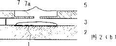
图2是用于示出当图1所示的喷射头驱动时液体是如何以液滴形式喷射的图。FIG. 2 is a diagram for illustrating how liquid is ejected in the form of droplets when the ejection head shown in FIG. 1 is driven.
图3是图1所示的液体喷射头的第一改进式样的剖面图。Fig. 3 is a sectional view of a first modification of the liquid ejecting head shown in Fig. 1 .
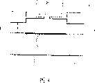
图4是图1所示的液体喷射头的第二改进式样的剖面图。Fig. 4 is a sectional view of a second modification of the liquid ejecting head shown in Fig. 1 .
图5是图1所示的液体喷射头的第三改进式样的剖面图。Fig. 5 is a sectional view of a third modification of the liquid ejecting head shown in Fig. 1 .
具体实施方式Detailed ways
下面将参照附图描述本发明的实施例。Embodiments of the present invention will be described below with reference to the accompanying drawings.
图1示出了本发明的一实施例中的液体喷射头,图1(a)是其平面图,图1(b)是在图1(a)的平面X-X上的剖面图。1 shows a liquid jet head in one embodiment of the present invention, FIG. 1(a) is its plan view, and FIG. 1(b) is a sectional view on the plane X-X of FIG. 1(a).
图1所示的液体喷射头包含设有加热器1的基板2,该加热器是作为用于产生液体喷射的能量的元件。加热器1位于液体路径内。虽然图1示出了一个加热器1和一个液体路径3的组合,但在单个基板2上设置有多个加热器1,每个液体路径3都有一个加热器1。能量产生元件的选择不必限于电热转换元件。例如,可以是振动能量产生元件,比如压电元件。The liquid ejection head shown in FIG. 1 includes a
每一液体路径3被具有喷射出口4的喷射出口板5、基板2和用于限定喷射出口板5和基板2之间距离的间隙限定部件6围绕,其中液体经所述喷射出口以液滴形式喷射出。Each liquid path 3 is surrounded by an
所述喷射出口设有限流部分7,在此处,喷射出口直径比其他部分明显小,该限流部分7设于从喷射出口4在喷射出口板上5开口的喷射出口平面5a下凹的位置。这样,待喷射的液体保持在喷射出口的大直径部分内喷射出口平面5a和限流部分7形成的凹槽中,形成横跨喷射出口的外部开口的弯月面。所以,限流部分7在液体路径3和喷射出口板5的喷射出口面5a之间的液体中。The jet outlet is provided with a flow-restricting
下面将给出图1所示的液体喷射头的具体测量值。Specific measured values of the liquid ejecting head shown in Fig. 1 will be given below.
加热器1是方形的,且每一边缘为10μm长。至于喷射出口4的测量值,其直径在喷射出口平面5a处为10μm(直径a),在底部开口处为3μm;换言之,限流部分7的小孔7a的直径b为3μm。限流部分7的厚度为1μm。从限流部分7的顶面到喷射出口板5的喷射出口平面5a的距离d为4μm,而液体路径3的高度e(间隙限定部件的高度)为5μm。喷射出口板5的厚度f为5μm。The
在本发明的液体喷射头中,小孔7a的面积大小So和加热器1的表面面积大小Sh满足下述关系:So≤Sh。描述得更具体一些,在图1所示的液体喷射头的情况下,Sh=100μm2,而So=7.07μm2,满足:So≤Sh。而且,在本发明的液体喷射头中,限流部分7的厚度c和液体路径3的高度e满足下述关系:c≤e。而且,在本发明的液体喷射头的情况下,限流部分7的厚度c和从限流部分7的顶面到喷射出口板5的喷射出口平面5a的距离d满足下述关系:c≤d。在图1所示的液体喷射头的情况下,c=1μm,d=4μm,如上所述,满足:c≤d。In the liquid jet head of the present invention, the area size So of the
下面将描述上述液体喷射头的液体喷射动作图2示出了当如图1所示构成的喷射头受到驱动时是如何喷射液体的。Next, the liquid ejecting action of the above liquid ejecting head will be described. FIG. 2 shows how liquid is ejected when the ejecting head constructed as shown in FIG. 1 is driven.
参照图1,在液体喷射头开始驱动之前,弯月面8覆盖着喷射出口板5的每一喷射出口4的外部开口,所以,限流部分7的小孔7a在液体中。下面,参照图2(a),当为了喷射液体而将电压施加到加热器1上时,加热器1产生热量,加热液体路径3中接触加热器1表面的液体。结果,液体以膜态方式沸腾,产生气泡。随着气泡的产生,气泡的体积快速增大,致使一部分液体向下游(朝喷射出口4)移动,而另一部分向上游(朝液体供应侧)移动。当所述液体部分朝喷射出口4移动时,它经过限流部分7的小孔7a,且当它经过小孔7a时,明显加速。结果,在喷射出口4的上述凹槽中,在位置上对应小孔7a的那部分液体,比包围在位置上对应小孔7a的那部分液体的液体移动更快。Referring to FIG. 1, before the liquid ejection head starts to drive, the
所以,覆盖喷射出口外部开口的弯月面8的在位置上对应小孔7a的中心部分,被在位置上对应小孔7a的上述快速移动的液体向上猛推。结果,喷射出液滴10。在这种情况下,喷射出口4的凹槽中的墨水整体没有喷射;换言之,喷射出体积非常小(0.014pl)的液滴。而且,喷射出口4的凹槽中的液体的基本部分保留在凹槽中。所以,小孔7a保持在液体中,从而避免出现随着液体的干涸而使小孔阻塞的问题。这样,如上所述构成的液体喷射头可以从液体喷射动作的最开始就喷射理想的液滴。Therefore, the central portion of the
图3示出了图1所示的液体喷射头的第一改进式样。这种改进与图1所示液体喷射头的不同之处在于限流部分7的小孔7a是锥形的,从而使其在液体路径一侧,或内侧比喷射出口平面5a一侧的直径更大。即使限流部分7的小孔7a如上所述是锥形的,也可以获得类似于图1所示的液体喷射头的效果,只要满足上述关系式,即So≤Sh,c≤e,和/或c≤d。顺便提及的是,图3示出的小孔7a,其直径从液体路径3一侧朝喷射出口平面5a逐渐减小。然而,小孔7a的锥形也可以这样,即小孔7a的直径从喷射出口平面5a朝液体路径3一侧逐渐减小,或小孔7a的直径从液体路径3一侧朝液体路径3和喷射出口平面5a之间的给定点逐渐减小,然后从该点朝喷射出口平面5a逐渐增加。而且,限流部分7的小孔7a的边缘可以是圆的。换言之,只要限流部分7的小孔7a是锥形的,它的直径朝液体路径或凹槽逐渐减小或增加,那么它的结构是可任选的。FIG. 3 shows a first modification of the liquid ejection head shown in FIG. 1. FIG. This modification differs from the liquid ejection head shown in FIG. 1 in that the
图4示出了图1所示的液体喷射头的第二改进式样。图4所示的液体喷射头与图1所示的液体喷射头的不同之处在于限流部分7位于喷射出口板5的喷射出口4的外边缘和用于限定液体路径3的高度的限定部件6的顶面之间。即使限流部分7在喷射出口4中的位置变成从喷射出口平面5a下凹的位置,也可以实现类似于由图1所示的液体喷射出口实现的效果,只要满足上述关系式:So≤Sh,c≤e,和/或c≤d。FIG. 4 shows a second modification of the liquid ejection head shown in FIG. 1. Referring to FIG. The difference between the liquid ejection head shown in FIG. 4 and the liquid ejection head shown in FIG. 1 is that the restricting
图5示出了图1所示的液体喷射头的第三改进式样。在图5所示的液体喷射头中,限流部分7具有多个小孔7a,该孔与一个加热器1相对。这种每一喷射出口4具有多个小孔7a的结构配置,不仅可以获得类似于上述的效果,而且可以同时从每一喷射出口4喷射多个液滴。FIG. 5 shows a third modification of the liquid ejection head shown in FIG. 1 . In the liquid ejecting head shown in FIG. 5, the restricting
顺便提及的是,上述的第一至第三改进式样中的结构配置不仅可以单独地用于本发明的液体喷射头,而且其任意组合也可以用于本发明的液体喷射头。Incidentally, the structural configurations in the first to third modifications described above can be used not only individually but also in any combination thereof for the liquid ejection head of the present invention.
本发明的液体喷射头喷射(包括雾化)非常微小的液滴形式的液体,所以可以大力推荐其作为比如喷墨记录领域的喷墨记录头的设备的液体喷射头,和药物领域的液体药物吸入器头。The liquid ejection head of the present invention ejects (including atomizes) liquid in the form of very fine droplets, so it can be highly recommended as a liquid ejection head for devices such as an inkjet recording head in the field of inkjet recording, and a liquid medicine in the field of medicine inhaler head.
当本发明的液体喷射头用作喷墨记录头时,它的喷射出口沿一条或多条直线布置,至于待喷射的液体,使用记录液体,比如墨水,或在墨水喷射之前粘附于记录纸上的表面处理液,以防止墨水渗透记录纸。喷射出口排列的方向和/或喷射出口排列的直线长度可以根据需要变化,以形成用于串行式喷墨记录设备的喷墨记录头,或者用于行式喷墨记录设备的喷墨记录头。尤其是,当本发明的液体喷射头用作串行式喷墨记录设备的喷墨记录头时,可以将液体喷射头和装有供应到液体喷射头的记录液体的容器以可以为一体或分开的卡盒的形式构成。When the liquid ejection head of the present invention is used as an inkjet recording head, its ejection outlets are arranged along one or more straight lines, and as the liquid to be ejected, use a recording liquid such as ink, or adhere to recording paper before ink ejection surface treatment fluid on the surface to prevent ink from penetrating the recording paper. The direction in which the ejection outlets are arranged and/or the linear length of the ejection outlets arrangement can be changed as needed to form an inkjet recording head for a serial type inkjet recording device, or an inkjet recording head for a line type inkjet recording device . In particular, when the liquid ejection head of the present invention is used as an ink jet recording head of a serial type ink jet recording apparatus, the liquid ejection head and the container containing the recording liquid supplied to the liquid ejection head may be integrally or separately Formed in the form of a card box.
如上所述,本发明的液体喷射头在喷墨记录领域可以用于喷射记录墨水。As described above, the liquid ejection head of the present invention can be used for ejecting recording ink in the field of inkjet recording.
而且,本发明的液体喷射头也可以用作液体药物吸入设备的吸入头。在这种情况下,液体喷射头可以连接于液体药物分配器。至于喷射的药物,有比如胰岛素、人体生长激素、促生殖腺激素等蛋白质制剂;烟碱;麻醉剂等。Furthermore, the liquid ejection head of the present invention can also be used as an inhalation head of a liquid medicine inhalation device. In this case, the liquid ejection head may be connected to the liquid drug dispenser. As for the sprayed drugs, there are protein preparations such as insulin, human growth hormone, and gonad-stimulating hormone; nicotine; anesthetics, etc.
Claims (6)
Applications Claiming Priority (9)
| Application Number | Priority Date | Filing Date | Title |
|---|---|---|---|
| JP2001358292AJP2003154665A (en) | 2001-11-22 | 2001-11-22 | Liquid ejection head |
| JP2001358293AJP2003154655A (en) | 2001-11-22 | 2001-11-22 | Liquid ejection head |
| JP358291/2001 | 2001-11-22 | ||
| JP358293/01 | 2001-11-22 | ||
| JP358291/01 | 2001-11-22 | ||
| JP358292/01 | 2001-11-22 | ||
| JP358293/2001 | 2001-11-22 | ||
| JP2001358291AJP2003154664A (en) | 2001-11-22 | 2001-11-22 | Liquid ejection head |
| JP358292/2001 | 2001-11-22 |
Publications (2)
| Publication Number | Publication Date |
|---|---|
| CN1491162A CN1491162A (en) | 2004-04-21 |
| CN100339219Ctrue CN100339219C (en) | 2007-09-26 |
Family
ID=27347865
Family Applications (1)
| Application Number | Title | Priority Date | Filing Date |
|---|---|---|---|
| CNB028050363AExpired - Fee RelatedCN100339219C (en) | 2001-11-22 | 2002-11-22 | liquid jet head |
Country Status (8)
| Country | Link |
|---|---|
| US (1) | US6926392B2 (en) |
| EP (1) | EP1447221B1 (en) |
| KR (2) | KR20060028658A (en) |
| CN (1) | CN100339219C (en) |
| AT (1) | ATE448085T1 (en) |
| CA (1) | CA2436011C (en) |
| DE (1) | DE60234373D1 (en) |
| WO (1) | WO2003043826A1 (en) |
Families Citing this family (21)
| Publication number | Priority date | Publication date | Assignee | Title |
|---|---|---|---|---|
| JP4147234B2 (en)* | 2004-09-27 | 2008-09-10 | キヤノン株式会社 | Discharge liquid, discharge method, cartridge, and discharge device |
| WO2005037557A1 (en) | 2003-10-22 | 2005-04-28 | Canon Kabushiki Kaisha | Liquid jetting head |
| JP4936900B2 (en)* | 2003-12-30 | 2012-05-23 | フジフィルム ディマティックス, インコーポレイテッド | Droplet ejection assembly |
| JP4147235B2 (en)* | 2004-09-27 | 2008-09-10 | キヤノン株式会社 | Discharge liquid, discharge method, droplet forming method, liquid discharge cartridge, and discharge apparatus |
| JP2006087815A (en)* | 2004-09-27 | 2006-04-06 | Canon Inc | Spraying method and spraying device based on the method |
| JP4632421B2 (en)* | 2004-12-07 | 2011-02-16 | キヤノン株式会社 | Inkjet recording head |
| JP2006212203A (en)* | 2005-02-03 | 2006-08-17 | Canon Inc | Inhalation device and liquid agent discharge cartridge |
| JP4646669B2 (en)* | 2005-03-30 | 2011-03-09 | キヤノン株式会社 | Discharge liquid, discharge method, droplet forming method, cartridge, and discharge device |
| JP4689340B2 (en)* | 2005-05-02 | 2011-05-25 | キヤノン株式会社 | Liquid pharmaceutical composition for discharge |
| JP4777225B2 (en)* | 2006-12-04 | 2011-09-21 | キヤノン株式会社 | Discharge liquid and discharge method |
| JP4428391B2 (en)* | 2007-03-14 | 2010-03-10 | セイコーエプソン株式会社 | Fluid ejecting head and fluid ejecting apparatus |
| US7746769B2 (en)* | 2007-03-26 | 2010-06-29 | Alcatel Lucent | Management of redundant and multi-segment pseudo-wire |
| JP5424556B2 (en)* | 2007-12-07 | 2014-02-26 | キヤノン株式会社 | Liquid discharge head having discharge ports that do not have rotational symmetry |
| JP2009286047A (en)* | 2008-05-30 | 2009-12-10 | Canon Inc | Liquid jetting method and liquid jetting apparatus |
| JP2010207297A (en)* | 2009-03-09 | 2010-09-24 | Canon Inc | Liquid discharge device and method therefor |
| JP2010246669A (en)* | 2009-04-14 | 2010-11-04 | Canon Inc | Liquid discharge head for inhaler and inhaler |
| US9586399B2 (en) | 2015-03-30 | 2017-03-07 | Funai Electric Co., Ltd. | Fluid ejection device for depositing a discrete quantity of fluid onto a surface |
| US9889651B2 (en) | 2015-03-30 | 2018-02-13 | Funai Electric Co., Ltd. | Fluid ejection device for depositing a discrete quantity of fluid onto a surface |
| JP2018051980A (en) | 2016-09-29 | 2018-04-05 | エスアイアイ・プリンテック株式会社 | Injection hole plate, liquid injection head, and liquid injection device |
| EP3468801B1 (en)* | 2016-10-14 | 2023-07-26 | Hewlett-Packard Development Company, L.P. | Fluid ejection device |
| JP2018199235A (en)* | 2017-05-26 | 2018-12-20 | キヤノン株式会社 | Liquid discharge head |
Citations (6)
| Publication number | Priority date | Publication date | Assignee | Title |
|---|---|---|---|---|
| JPS6137429A (en)* | 1984-07-31 | 1986-02-22 | Dainippon Ink & Chem Inc | Double-sided printing machine |
| JPS61262131A (en)* | 1985-05-16 | 1986-11-20 | Olympus Optical Co Ltd | Method for recording image under control of image density in ink jet printer |
| JPS6319263A (en)* | 1986-07-11 | 1988-01-27 | Seiko Epson Corp | Inkjet recording device |
| JPH06143567A (en)* | 1992-11-09 | 1994-05-24 | Seiko Epson Corp | Ink jet head |
| EP1016525A2 (en)* | 1998-12-29 | 2000-07-05 | Canon Kabushiki Kaisha | Liquid-ejecting head, liquid-ejecting method and liquid-ejecting printing apparatus |
| US6313435B1 (en)* | 1998-11-20 | 2001-11-06 | 3M Innovative Properties Company | Mask orbiting for laser ablated feature formation |
Family Cites Families (18)
| Publication number | Priority date | Publication date | Assignee | Title |
|---|---|---|---|---|
| JPH064320B2 (en)* | 1984-07-31 | 1994-01-19 | キヤノン株式会社 | Inkjet recording head |
| JP2658204B2 (en)* | 1988-06-30 | 1997-09-30 | 富士ゼロックス株式会社 | Ink jet recording device |
| JP3179834B2 (en)* | 1991-07-19 | 2001-06-25 | 株式会社リコー | Liquid flight recorder |
| JPH05193141A (en) | 1992-01-20 | 1993-08-03 | Seiko Epson Corp | Inkjet head |
| AU712741B2 (en)* | 1995-04-26 | 1999-11-18 | Canon Kabushiki Kaisha | Liquid ejecting head, liquid ejecting device and liquid ejecting method |
| US5821962A (en)* | 1995-06-02 | 1998-10-13 | Canon Kabushiki Kaisha | Liquid ejection apparatus and method |
| JP3403008B2 (en)* | 1996-07-05 | 2003-05-06 | キヤノン株式会社 | Liquid ejection head, head cartridge and recording apparatus using the same |
| JP3403009B2 (en)* | 1996-07-12 | 2003-05-06 | キヤノン株式会社 | Liquid discharge method involving displacement of movable member and bubble growth, liquid discharge head used for the discharge method, head cartridge, and liquid discharge apparatus using these |
| JP3372827B2 (en)* | 1996-07-12 | 2003-02-04 | キヤノン株式会社 | Liquid discharge method, liquid discharge head, head cartridge using the discharge head, and liquid discharge device |
| US6174049B1 (en) | 1996-07-31 | 2001-01-16 | Canon Kabushiki Kaisha | Bubble jet head and bubble jet apparatus employing the same |
| US6350016B1 (en)* | 1998-02-10 | 2002-02-26 | Canon Kabushiki Kaisha | Liquid ejecting method and liquid ejecting head |
| JPH11334069A (en) | 1998-05-27 | 1999-12-07 | Oki Data Corp | Ink jet head |
| AU766832B2 (en)* | 1998-07-28 | 2003-10-23 | Canon Kabushiki Kaisha | Liquid discharging head and liquid discharging method |
| KR100340894B1 (en)* | 1998-07-28 | 2002-06-20 | 미다라이 후지오 | Liquid discharging head, liquid discharging method and liquid discharging apparatus |
| US6409317B1 (en)* | 1998-08-21 | 2002-06-25 | Canon Kabushiki Kaisha | Liquid discharge head, liquid discharge method and liquid discharge apparatus |
| JP3797648B2 (en) | 1999-07-27 | 2006-07-19 | キヤノン株式会社 | Liquid discharge head and recording apparatus using the liquid discharge head |
| JP2002210965A (en)* | 2001-01-17 | 2002-07-31 | Seiko Epson Corp | Nozzle plate, ink jet recording head, and ink jet recording apparatus |
| JP2002321364A (en)* | 2001-04-25 | 2002-11-05 | Fuji Photo Film Co Ltd | Ink jet recording head and ink jet printer |
- 2002
- 2002-11-22WOPCT/JP2002/012235patent/WO2003043826A1/ennot_activeApplication Discontinuation
- 2002-11-22KRKR1020067003834Apatent/KR20060028658A/ennot_activeCeased
- 2002-11-22ATAT02790699Tpatent/ATE448085T1/ennot_activeIP Right Cessation
- 2002-11-22CACA002436011Apatent/CA2436011C/ennot_activeExpired - Fee Related
- 2002-11-22EPEP02790699Apatent/EP1447221B1/ennot_activeExpired - Lifetime
- 2002-11-22DEDE60234373Tpatent/DE60234373D1/ennot_activeExpired - Lifetime
- 2002-11-22CNCNB028050363Apatent/CN100339219C/ennot_activeExpired - Fee Related
- 2002-11-22KRKR10-2003-7009670Apatent/KR20040020879A/ennot_activeCeased
- 2003
- 2003-07-17USUS10/620,421patent/US6926392B2/ennot_activeExpired - Fee Related
Patent Citations (6)
| Publication number | Priority date | Publication date | Assignee | Title |
|---|---|---|---|---|
| JPS6137429A (en)* | 1984-07-31 | 1986-02-22 | Dainippon Ink & Chem Inc | Double-sided printing machine |
| JPS61262131A (en)* | 1985-05-16 | 1986-11-20 | Olympus Optical Co Ltd | Method for recording image under control of image density in ink jet printer |
| JPS6319263A (en)* | 1986-07-11 | 1988-01-27 | Seiko Epson Corp | Inkjet recording device |
| JPH06143567A (en)* | 1992-11-09 | 1994-05-24 | Seiko Epson Corp | Ink jet head |
| US6313435B1 (en)* | 1998-11-20 | 2001-11-06 | 3M Innovative Properties Company | Mask orbiting for laser ablated feature formation |
| EP1016525A2 (en)* | 1998-12-29 | 2000-07-05 | Canon Kabushiki Kaisha | Liquid-ejecting head, liquid-ejecting method and liquid-ejecting printing apparatus |
Also Published As
| Publication number | Publication date |
|---|---|
| KR20040020879A (en) | 2004-03-09 |
| US6926392B2 (en) | 2005-08-09 |
| CA2436011C (en) | 2009-03-10 |
| ATE448085T1 (en) | 2009-11-15 |
| WO2003043826A1 (en) | 2003-05-30 |
| CA2436011A1 (en) | 2003-05-30 |
| EP1447221A4 (en) | 2005-06-15 |
| CN1491162A (en) | 2004-04-21 |
| KR20060028658A (en) | 2006-03-30 |
| DE60234373D1 (en) | 2009-12-24 |
| US20050073556A1 (en) | 2005-04-07 |
| EP1447221B1 (en) | 2009-11-11 |
| EP1447221A1 (en) | 2004-08-18 |
Similar Documents
| Publication | Publication Date | Title |
|---|---|---|
| CN100339219C (en) | liquid jet head | |
| JP6327493B2 (en) | Printing device | |
| EP0770487A1 (en) | Non-circular printhead orifice | |
| WO2005014180A1 (en) | Electrostatic suction-type fluid discharging method and device | |
| US20210331469A1 (en) | Industrial printhead | |
| US20160243827A1 (en) | Controlling air and liquid flows in a two-dimensional printhead array | |
| CN110139759A (en) | Actuator for fluid delivery system | |
| JP2010105184A (en) | Droplet delivery device | |
| US6886924B2 (en) | Droplet ejection device | |
| KR102534891B1 (en) | Print head design for ballistic aerosol marking with smooth particulate injection from an array of inlets into a matching array of microchannels | |
| JP4397642B2 (en) | Electrostatic suction type fluid discharge method and apparatus | |
| JP5424556B2 (en) | Liquid discharge head having discharge ports that do not have rotational symmetry | |
| JP2005058806A (en) | Electrostatic suction type fluid discharge method and apparatus | |
| JP2003154655A (en) | Liquid ejection head | |
| KR20050054956A (en) | Electrostatic suction type fluid jettint device | |
| JP2010104863A (en) | Droplet discharge device | |
| JPH08196983A (en) | Thin film formation method | |
| WO2005037557A1 (en) | Liquid jetting head | |
| JP2003154665A (en) | Liquid ejection head | |
| JP3967297B2 (en) | Electrostatic suction type fluid discharge method and apparatus | |
| JPS6248587B2 (en) | ||
| US20020127014A1 (en) | Fluid dispensing method and apparatus employing piezoelectric transducer | |
| HK40002129B (en) | Industrial printhead | |
| JP2024076559A (en) | LIQUID EJECTION HEAD AND LIQUID EJECTION APPARATUS | |
| CN114849032A (en) | Drug delivery device, method of controlling a fluid plume and method of nasal injection |
Legal Events
| Date | Code | Title | Description |
|---|---|---|---|
| C06 | Publication | ||
| PB01 | Publication | ||
| C10 | Entry into substantive examination | ||
| SE01 | Entry into force of request for substantive examination | ||
| C14 | Grant of patent or utility model | ||
| GR01 | Patent grant | ||
| C17 | Cessation of patent right | ||
| CF01 | Termination of patent right due to non-payment of annual fee | Granted publication date:20070926 Termination date:20131122 |